OEM Controls ST550 ST-550 Radio Product User Manual Contents
OEM Controls, Inc. ST-550 Radio Product Contents
User Manual

ii
10 Controls Drive, Shelton CT 06484
203.929.8431
www.oemdd.com
WARNING: It is the purchaser’s responsibility to determine the suitability of any OEM
Controls, Inc. product for an intended application and to ensure that it is installed and guarded in accordance
with all federal, state, local and private safety and health regulations, codes and standards.
We can advise you of the various features that are available, but we believe that our customer’s engineering
departments should be qualified experts in their own product field. If the product will be used in a safety critical
application, the customer must undertake appropriate testing and evaluation to prevent injury to the ultimate
user.
Should you have any questions or if any of the above warning is unclear, please contact OEM Controls, Inc. at
10 Controls Drive, Shelton, CT, 06484, FAX: 203.929.3867, TEL: 203.929.8431
WARNING: Changes or modifications not expressly approved by the party responsible for
compliance could void the user’s authority to operate the equipment.
NOTE: This equipment has been tested and found to comply with the limits for a Class A digital device,
pursuant to part 15 of the FCC Rules. These limits are designed to provide reasonable protection against harmful
interference when the equipment is operated in a commercial environment. This equipment generates, uses, and
can radiate radio frequency energy and, if not installed and used in accordance with the instruction manual, may
cause harmful interference to radio communications. Operation of this equipment in a residential area is likely to
cause harmful interference in which case the user will be required to correct the interference at his own expense.
This device complies with part 15 of the FCC Rules. Operation is subject to the following two conditions: (1) This
device may not cause harmful interference, and (2) this device must accept any interference received, including
interference that may cause undesired operation.
This equipment complies with the FCC RF radiation exposure limits set forth for an uncontrolled environment.
This equipment should be installed and operated with a minimum distance of 20 centimeters between the
radiator and your body.
This device complies with Industry Canada licence-exempt RSS standard(s). Operation is subject to the following
two conditions: (1) this device may not cause interference, and (2) this device must accept any interference,
including interference that may cause undesired operation of the device.
Le présent appareil est conforme aux CNR d'Industrie Canada applicables aux appareils radio exempts de
licence. L'exploitation est autorisée aux deux conditions suivantes : (1) l'appareil ne doit pas produire de
brouillage, et (2) l'utilisateur de l'appareil doit accepter tout brouillage radioélectrique subi, même si le brouillage
est susceptible d'en compromettre le fonctionnement.

iii
Contents
Overview of the ST-550 ....................................................................... 1
Features .................................................................................................................................................................. 1
ST-550 Assembly with a Vibration Sensor Shown ................................................................................................ 2
Technical Specifications ......................................................................................................................................... 3
ST-550 Outline Dimensions and Interface Connectors .......................................................................................... 4
ST-550 Cables with Vibration Sensor .................................................................................................................... 5
Field Wiring (Supplied) for the ST-550 W/O a Vibration Sensor .......................................................................... 6
ST-550 Wiring Diagram Options ........................................................................................................................... 7
Section 2 8
Installation Procedures ...................................................................... 8
Before Staring: ................................................................................................................................................ 8
Installing the ST-550 .............................................................................................................................................. 8
The Battery Cable ............................................................................................................................................ 9
Installing the Vibration Sensor ............................................................................................................................. 10
Calibrating the ST-550 ......................................................................................................................................... 10
Upon Completion ................................................................................................................................................. 11
Trouble Shooting after the Installation of ST-550 W/O a Vibration Sensor ................................................. 12
Pass or Fail Counting Hours Test .................................................................................................................. 12
Setting the ST-550 Radio Program ....................................................................................................................... 13
Starting the Radio Program on the Supporting PDA ............................................................................................ 13
Selecting a Channel for Service Tracker .............................................................................................................. 14
Loading a New Profile .......................................................................................................................................... 14
Editing a Profile .................................................................................................................................................... 17
Copying a Profile to Another Service Tracker ..................................................................................................... 18
Deleting a Machine Profile ................................................................................................................................... 19
Downloading a Machine Profile ........................................................................................................................... 20
Communicating With the ...................................................................................................................................... 20
ST-550 .................................................................................................................................................................. 20
Data Loading Modes ............................................................................................................................................ 21
Collecting Data – Polling ..................................................................................................................................... 22
Viewing Equipment Maintenance Schedules ................................................................................................ 24
Entering Notes for this Equipment Number .................................................................................................. 24
Viewing Equipment Activity ................................................................................................................................ 24
Viewing A+I Notes, History, Com-Link and Service Alerts records ............................................................ 25
Section 3 27
Index ................................................................................................. 27
Figures
Figure 1.- ST-550 Service Tracker ........................................................................................................................ 1
Figure 2.- ST-550 Assembly with Vibration Sensor .............................................................................................. 2
Figure 3.- Table of Technical Specifications .......................................................................................................... 3
Figure 4.- ST-550 Outline and Dimensions ............................................................................................................ 4
Figure 5.- ST-550 Field Cables with a Vibration Sensor ........................................................................................ 5
Figure 6.- ST-550 OEM Manufactured Battery Cable-Optional ............................................................................ 6
Figure 7.- ST-550 Field Wiring without a Vibration Sensor using the Alternator Output ..................................... 6
Figure 8.- ST-550 Wiring Diagram W/O the Vibration Sensor Option ................................................................. 7
Figure 9.- ST-550 Wiring Diagram with the Vibration Sensor Option .................................................................. 7

Contents -STIB 22549 Rev. A
iv
Figure 10.- ST-550 Seven Segment Calibration Display Specifics ...................................................................... 11
Figure 11.- ST-550 Fast and Slow Pulse Display ................................................................................................. 12
Figure 12.- Setting the ST-550 Radio Tracker Program ....................................................................................... 13
Document Revision History
OEM Controls Inc; All rights reserved.
Disclaimer and Limitation of Liability
Document Number:
Revision: B
Date of Revision: 4/26/2011
About this guide:
This guide provides basic instruction on the installation and use of the ST-550
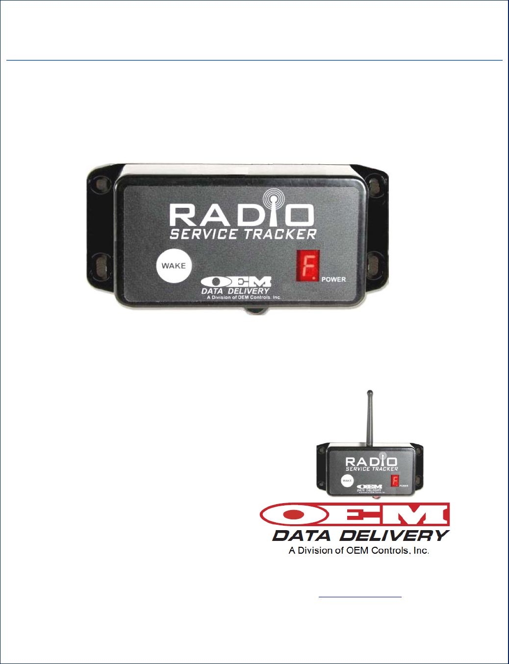
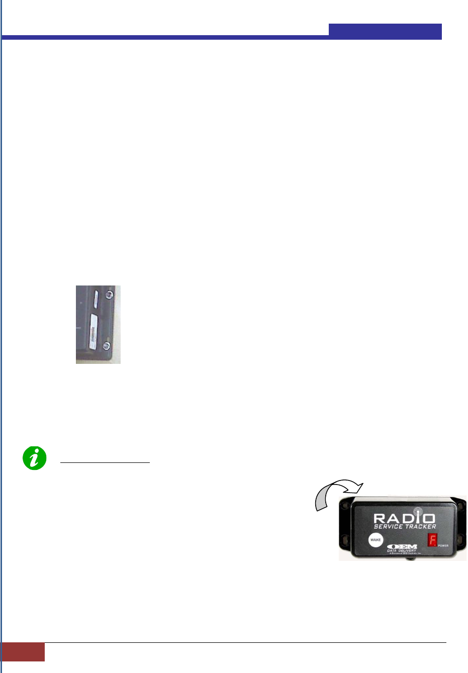
About the Cover
Shown on the cover are two (2) versions of the ST-550 Service Tracker supported by
OEM Data Delivery, Inc. The ST-550 featured on the cover, (center) is an (I) version with an
internal antenna. (ST-550 I) Also pictured is the ST-550 (pictured lower right and still supported)
with an external antenna. Both units are now furnished with a pigtail cable (not shown) and
identified by P/N ST-550 IC- Internal antenna and cable and P/N ST-550 C External antenna and
cable.
Confidential and Proprietary, Property of OEM Data Delivery a Division of OEM Controls, Inc.|
Section 2
1
Section 1
Overview of the ST-550
This document will serve the user of this equipment as a Manual of Operations and
basic troubleshooting guide, thereby allowing for the proper installation and use of
the ST-550 Service Tracker.
This section provides an overview of the ST-550 Service Tracker System.
Features
Radio Terminal Downloader
Travel logs are logged every (6) minutes while the
vehicle is in motion
Work/Idle/Run/Count and Duration logs recorded.
Cumulative Machine Hours (CMH) compiled.
7 User Programmable Service Alerts.
Power conservation (Sleep State).
The Service Tracker (ST-550) is a radio device that compiles and stores work/ idle,
run and maintenance logs; connectivity is accomplished in RS232 and USB format
via a secure radio link. The ST-550 does not support IrDA communication.
In the operation mode, an ST-550 mounted on the dash board or on the top of the
vehicle, has been logging in CMH (Cumulative Machine Hours), and compiling
maintenance service times on the vehicle. Each maintenance procedure is assigned a
Service Tracker number (up to seven different procedures can be tracked). The
maintenance issues are displayed as service alerts. Each service alert has a designated
identifier number (one through seven) that display on the “window eye” of the ST-
550. The number indicates that a particular maintenance procedure should be
completed. When the service alert is satisfied the counter is reset with any supporting
PDA (Personal Data Assistant).
Retrieving the ST-550 data, such as the profile, service alerts, work/ idle/ run/
count/duration logs is accomplished with a supporting PDA, or by using the OEM
Data Delivery manufactured mobile CPU called GoPOD. The GoPOD is configured
with 512 MB Memory, 1 GB CF, Windows XP Embedded for ease of use. The
housing is designed to be installed on a lube or fuel truck, low boy truck, mechanics’
truck or supervisor’s vehicle. The GoPOD is equipped with a GPS antenna, and a
radio antenna. Information is collected passively, from the ST-550 and “hands-free”.
GPS coordinates are automatically stamped into the record as hourly data is collected.
Information is collected via drive-by, within a range of 300 ft. line of site, and
transmitted via secure radio link.
Figure 1.- ST-550 Service Tracker
Contents -STIB 22549 Rev. A
2
Section 2 | Overview and Technical Specifications
Data is then downloaded into a web report each night, and made available on a
password-protected website. Information easily integrates with any major back office
management system. There is never an interruption of equipment operation.
A supporting type PDA will also allow the user to update (modify) the real time
clock, as well as capturing the Work/Idle/Run, Count/Duration logs.
For systems without the GoPOD CPU: Use an external GPS antenna, if available, in
the proximity of the communication between the (ST-550) and the servicing
equipment, to gather location information.
When used with the OEM Data delivery Vibration Sensor, the service tracker can
differentiate the subtle differences in engine vibration, between run/work and idle,
and compile a report, for the user, on where fuel consumption occurs verses work
output.
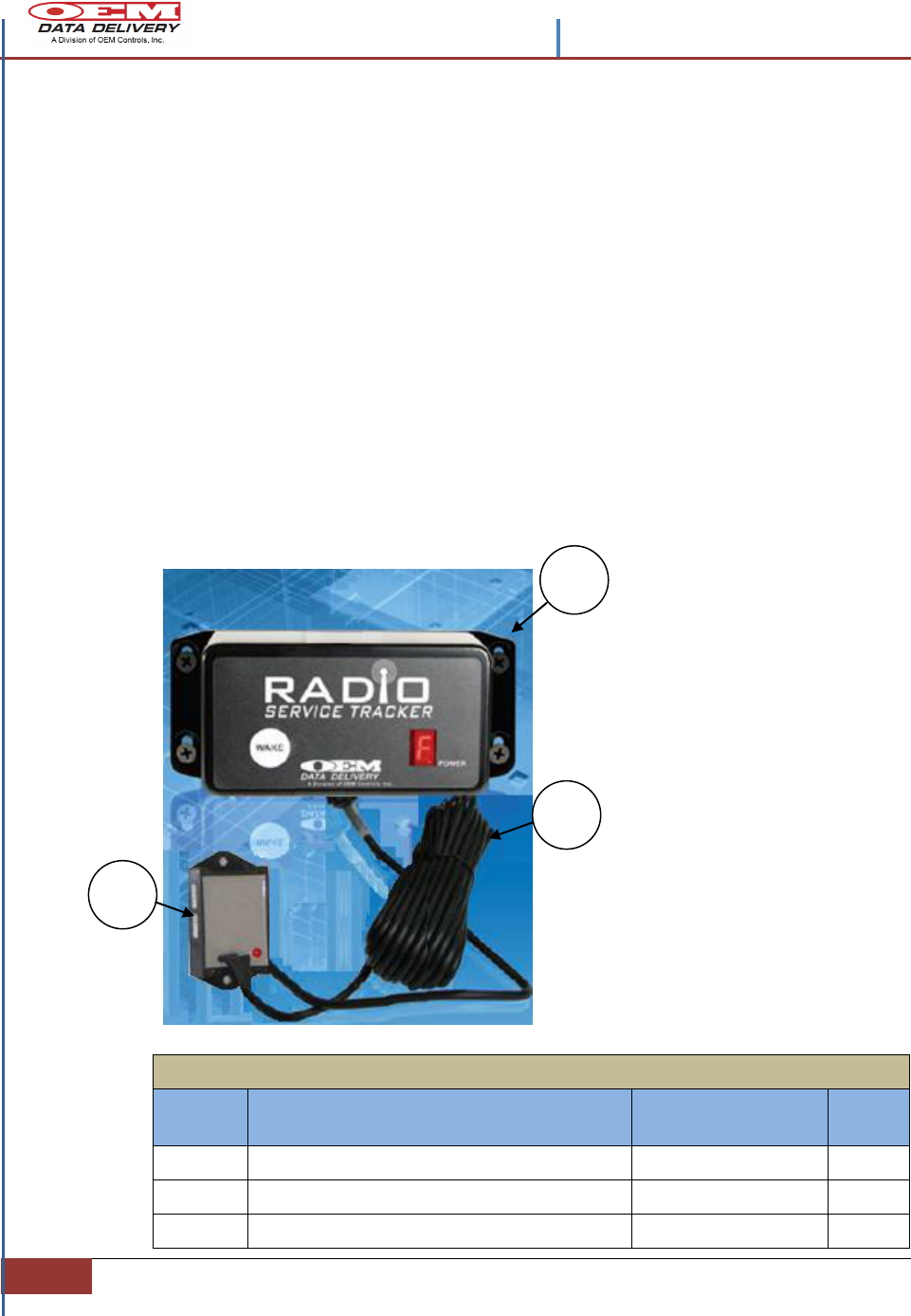
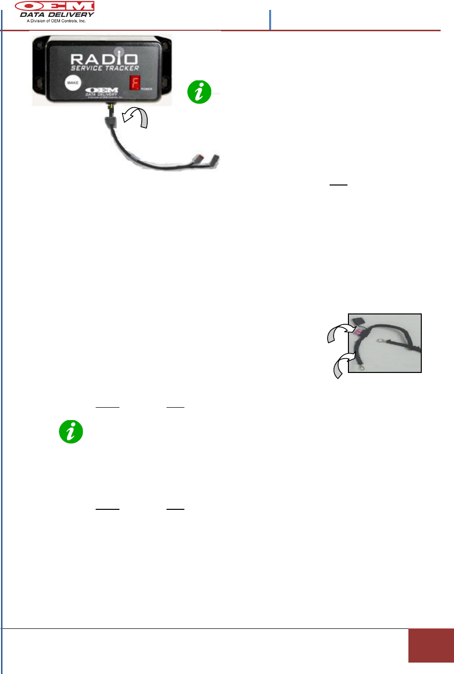
ST-550 Assembly with a Vibration Sensor
Shown
`
Figure 2.- ST-550IC Assembly with
Vibration Sensor
ST-550 ASSEMBLY With a Vibration Sensor
PIN #
Description
OEM Part Number
Qty
1
SERVICE TRACKER ST-550
ST-550IC
X
2
MAIN CABLE – SUPPLIED BY OEM
STWH-100A
1
3
VIBRATION SENSOR-Optional
ST-103A
1
1
2
OEM recommends use of
the Vibration Sensor (ST-
103) an OEM Controls, Inc.
product, for accuracy in
reading work and idle times
and for ease of installation.
If not used the OEM wiring
supplied with the service
tracker must be connected
to the vehicle alternator.
Cable shown is supplied for
Service Trackers with the
Vibration Sensor option.
3

Contents –STIB 22549 Rev. A
Confidential and Proprietary, Property of OEM Data Delivery a Division of OEM Controls, Inc.|
Section 2
3
Technical Specifications
Figure 3.- Table of Technical Specifications
ST-550IC TECHNICAL SPECFICATIONS
ITEM
DESCRIPTION
Material
Zinc IP67
Mounting Hardware
8-32 x 3/4 (recommended)
Manual Interface
WAKE Push Button
CH. 2 – Calibrating and radio channel switch during fuel mode.
CH. 1 – Diagnostic
Display
7 Segment Display for alarms, communication diagnostics, fuel mode, radio
GPRS, and connection status.
Real Time Clock
Date (+)Time Stamped Data
Operating Voltage
12VDC to 24VDC Range: 8-32v
Harness Power
(8 – 32 v DC), ground, ignition, 6 digital inputs, 2 digital outputs (1A, Max)
Data Logs
2 optically isolated digital inputs. 4 standard digital inputs
Memory
4K bytes of RAM, 64K bytes of ROM, no external EEPROM
Data Format
Comma Separated Value (CSV) Extensible Markup Language (XML), Open
Database Connectivity (OBDC),
Storage
Up to 34 days of saved history for each Idle/Work/ Run/ Count/ Duration log.
Environmental
Temperature
-40°C +70°C
Radio
802.15.4 physical layer, normal operating frequency (240.5 MHz)
Antenna
2.4GHz Internally mounted.
Communication
interfaces
Radio, RS 232 serial and USB. The primary or the master devices mode of
operation is radio mode. It does not support IrDA communication. In the
radio mode the primary initiates the communication. The primary receives
tokens from a PC/ PDA command interface.
Warranty
Standard 1 year
Contents -STIB 22549 Rev. A
4
Section 2 | Overview and Technical Specifications
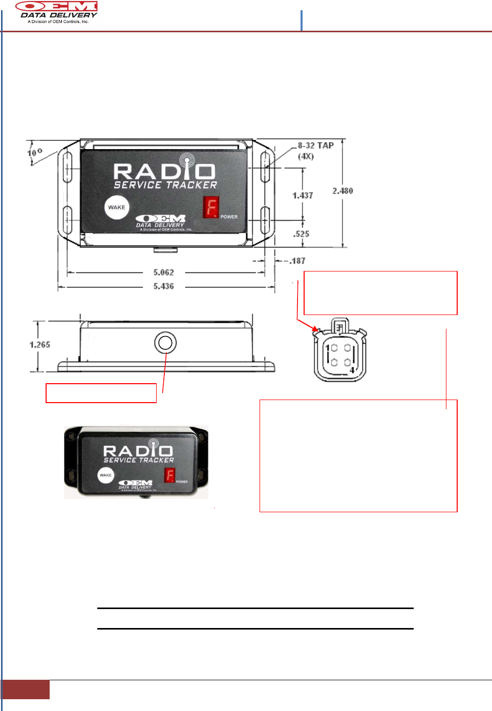
ST-550 Outline Dimensions and Interface
Connectors
Figure 4.- ST-550 IC Outline and Dimensions
Note: All dimensions are in inches.
OEM P/N EPCN/1485
4 Position Socket,
VIEWED FROM THE SOCKET SIDE.
FOR WIRING INFORMATION SEE FIGURE 7.
IF A VIBRATION SENSOR IS INCLUDED THEN
THIS CONNECTOR IS PRE-WIRED FROM
OEM CONTROLS, INC.
ALIGN MATING CONNECTOR
KEYWAYS, BEFORE STARTING TO
MATE CONNECTORS
WIRE GROMMET
Contents –STIB 22549 Rev. A
Confidential and Proprietary, Property of OEM Data Delivery a Division of OEM Controls, Inc.|
Section 2
5
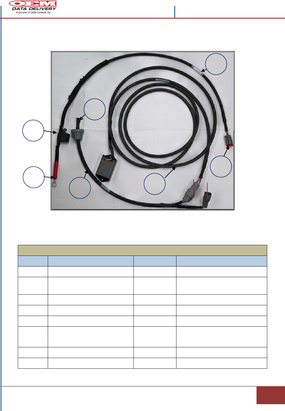
ST-550 Cables with Vibration Sensor
Figure 5.- ST-550 Field Cables with a Vibration Sensor
STWH-200 CABLE HARNESSES for the ST-550 WITH a VIBRATION SENSOR
ITEM
DESCRIPTION
OEM P/N
CONNECTION
1
ST-550 PIGTAIL CABLE
STWH-200A
ST-550 TO P1 AND J2
2
VIBRATION SENSOR CABLE
STWH-103A-
9FT
P2/J2 to VIBRATION SENSOR
3
BATTERY CABLE
STWH-100B
P1/J1 To BATTERY
4
RING TONGUE NON-INSULATED
EPWT/915
BATTERY TO J1/P1
5
HEAT SHRINK 1/8 X 1/16
EPSU/706
6
ST-550IC OEM SUPPLIED AND
PRE-WIRED TO INTERNAL
ELECTRONICS
ST-550IC
CABLE CONNECTED TO ST-550
WITH PROVISIONS FOR VIBRATION
SENSOR CONNECTIONS
7
AMP PINS (MALE-FEMALE)
EPWT/858
For ALL CONNECTORS
8
FUSE (SEE FUSE HOLDER)
3 OR 5 AMP
INSTALL IN FUSE HOLDER
1
3
2
6
8
4
7
P1/J1
J2/P2
Contents -STIB 22549 Rev. A
6
Section 2 | Overview and Technical Specifications
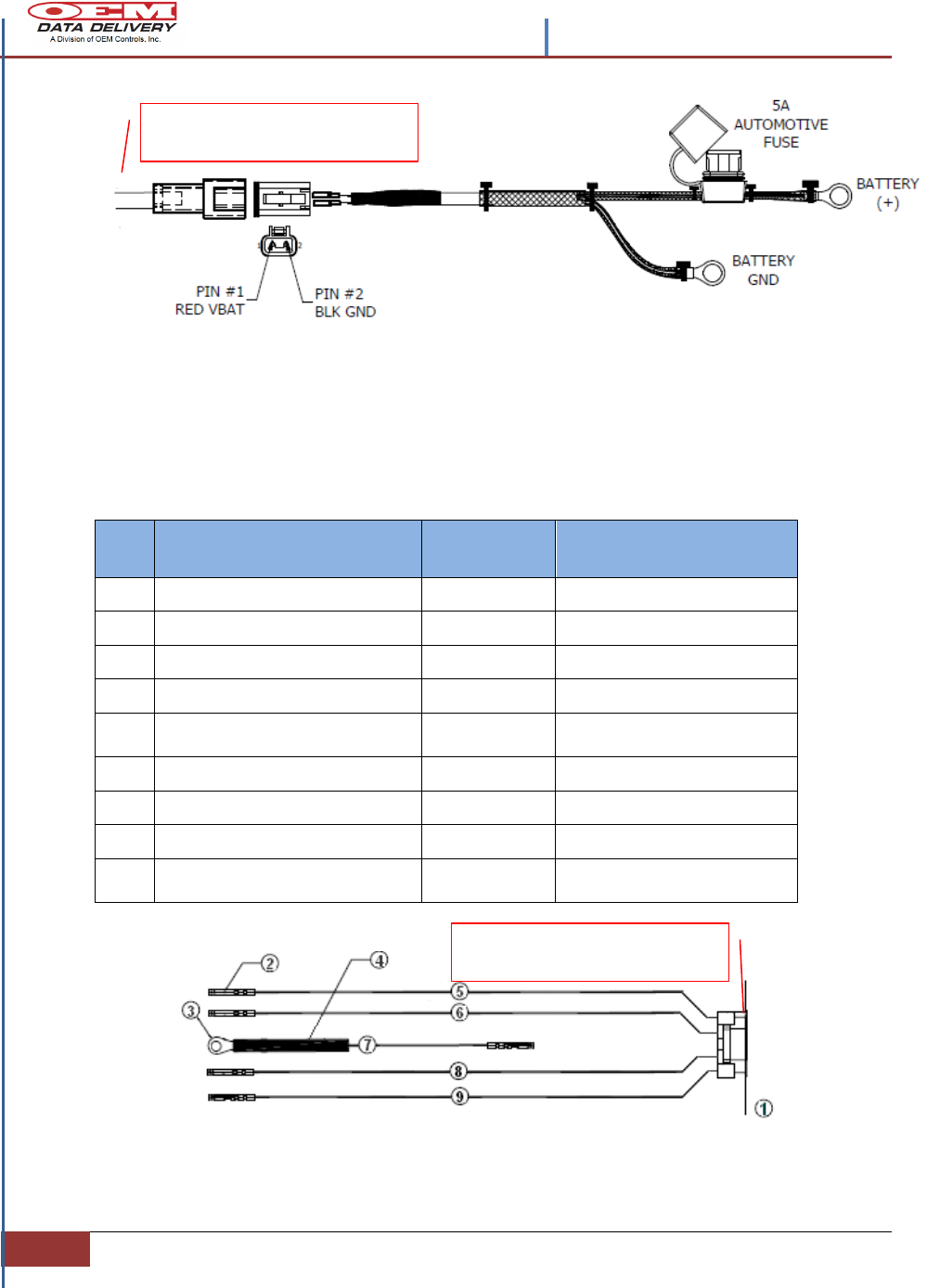
Figure 6.- ST-550 OEM Manufactured Battery Cable-Optional
Field Wiring (Supplied) for the ST-550 W/O a
Vibration Sensor
Figure 7.- ST-550 Field Wiring without a Vibration Sensor using the Alternator Output
ITEM
DESCRIPTION
OEM P/N
CONNECTION
1
ST-550C
C18694
C18694 EPLB/1080
2
CONTACTS (5) FEMALE PINS
EPWT/858
3
RING TONGUE
EPWT/915
4
HEAT SHRINK 1/8 X 1/16
EPSU/706
5
WIRE- RED 20/19 AWG
EPW8/252
POWER LINE BATTERY (+)
TO J1-1,2
6
WIRE- YELLOW 20/19 AWG
EPW8/256
FROM ALTERNATOR (+) 12V
7
WIRE- GREEN 20/19 AWG
EPW8/235
CHASSIS GROUND
8
WIRE- GREEN 20/19 AWG
EPW8/255
MASTER SWITCH
9
WIRE- BLACK 20/19 AWG
EPW8/258
POWER LINE BATTERY (-)
AND MASTER SWITCH
OEM- SUPPLIED HARNESS:
WIRE IDENTIFICATION
Connect to the ST-550 Red
and Black Wires
Contents –STIB 22549 Rev. A
Confidential and Proprietary, Property of OEM Data Delivery a Division of OEM Controls, Inc.|
Section 2
7
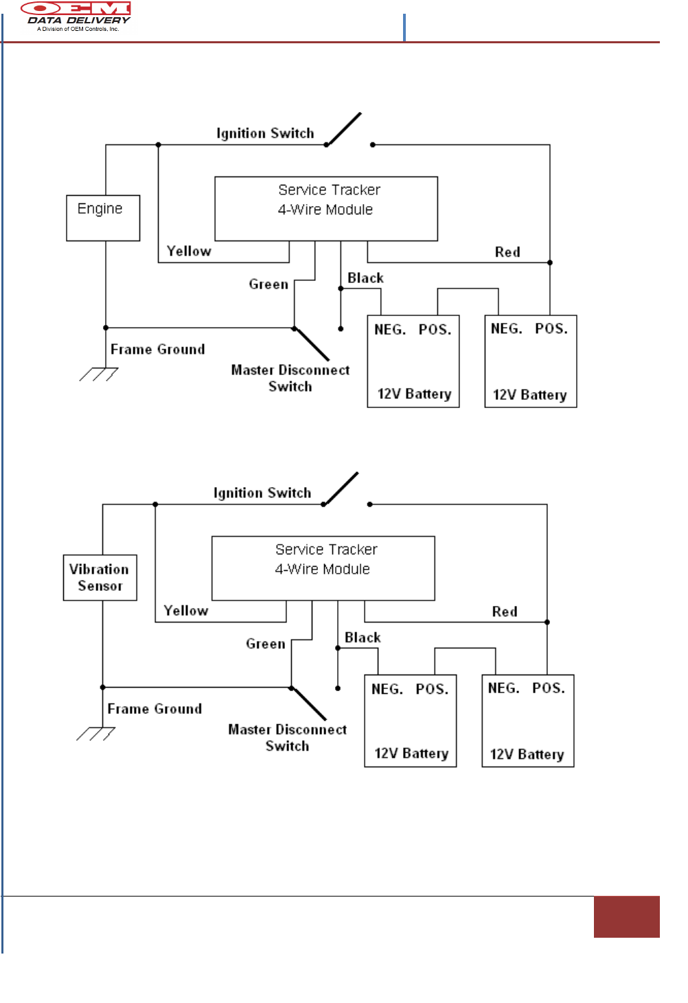
ST-550 Wiring Diagram Options
Figure 8.- ST-550 Wiring Diagram W/O the Vibration Sensor Option
Figure 9.- ST-550 Wiring Diagram with the Vibration Sensor Option
8
Section 2 | Installation Procedures
Section 2
Installation Procedures
How to… Correctly install the ST-550 (Radio Service Tracker) with the
Engine Vibration Sensor and Battery Harness.
Before Installing:
R
R
e
c
o
r
d
Record the ST-550 SERIAL NUMBER, located on the side of the
Service Tracker, and the MACHINE NUMBER that you are
installing the Service Tracker on, for reference purposes. This
information must be reported back to OEM Data Delivery for
tracking purposes.
Installing the ST-550
1. Turn off the engine and the master switch.
2. Visualize how to run the wires from the battery box and the engine to the
ST-550 Service Tracker.
Not recommended: Mounting the ST-550 in an enclosed environment such as
a battery box, metal engine bays, and closed cabs.
3. Mount the ST-550 on a flat surface with the
internal antenna pointed upward and secure the
enclosure using (4) four self- tapping screws.
4. Once the ST-550 is mounted, drill a hole (3) three
inches below the ST-550, and (15/16 inches) in
diameter.
5. Pull the pigtail harness from the battery and vibration sensor through this
hole. This will protect the harness from the elements and road hazards.
6. Plug the connector (J1) from the pigtail STWH/200A into the ST-550 and
push the two cables through the 15/16 inch drilled hole.
Check the machine frame voltage (e.g. positive or negative ground). The
ST-550 operates with a negative ground.
Installing the ST-550 harness: Be aware of moving parts, provide
adequate slack for wires around moving parts, then cable tie all wiring. Do
not have unsecured or hanging wires.
When mounting the Service Tracker, beware of compartments that open;
Example: Where a radiator assembly lifts up, as in a bob cat or other skid
steers. Choosing a secure location will prevent damaging the ST-900.
Before drilling check for obstructions and sensitive equipment (e.g.
radiators, hydraulic tanks, fuse boxes etc.).
Contents –STIB 22549 Rev. A
| Confidential and Proprietary, Property of OEM Data Delivery a Division of OEM Controls, Inc |
Section 2
9
If the ST-550 comes equipped with a Green
ground wire
7. Connect the ring terminal “GREEN”
wire to a chassis ground. (e.g., frame,
body, engine or frame side of master
switch).
NOTE: ST-550’s with a Vibration Sensor option will Not have a chassis
ground ring terminal.
The Battery Cable
1. Connect the battery harness ring terminal “RED” wire to the battery
positive 12VDC or 24VDC post.
2. Connect the battery harness ring terminal “BLACK” wire to the
ground post on the battery.
3. Run the battery cable back to the ST-550 and connect it to the pigtail
(supplied by OEM, See Figure 5).
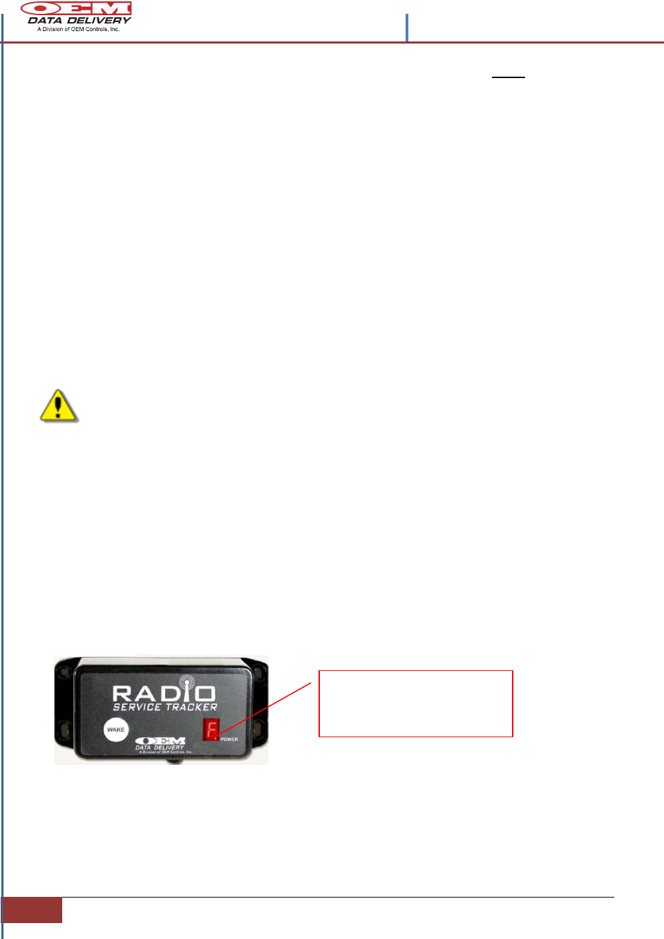
4. Put a 3 or 5 Amp Fuse (supplied by OEM) in the
fuse holder and close the cap. The window eye
light should be blinking on the ST-550.
5. The ST-550 now has power. Red Wire
6. Only if you’re Not using a Vibration Sensor, you will need to connect
the Yellow wire to a positive +12v or +24v power source that ONLY
has power while the machine is running (use Alternator “R” DC
terminal, to get both work and idle reading inputs if available). OEM
recommends use of the Vibration Sensor (ST-103) an OEM Controls,
Inc. product, for accuracy in reading work and idle times and for ease
of installation.
Only if you’re Not using a Vibration Sensor, You will need at least 7.0
volts “Motor Run” voltage when you connect to the Alternator with
the yellow wire. If the voltage source is adequate (Service Tracker will
start counting hours).
7. Secure the harness using cable-ties, leaving adequate slack in the
wires.
Plug the drilled hole with the rubber
grommet attached to the harness.
Grommet
Contents -STIB 22549 Rev. A
10
Section 2 | Installation Procedures
Mobile radios and high power AC equipment or transmission lines are
potential sources of interference. If interference is a problem a
shielded cable which is connected to chassis ground is advised.
Contact OEM Data Delivery for further assistance.
Installing the Vibration Sensor
Warning: This installation should not be attempted while the engine is
running.
1. Find a smooth surface on the engine block away
from any excessive heat source. The vibration
sensor must be securely mounted perpendicular
to the engine crankshaft, or parallel to the belts.
A good location is the alternator bracket or
some other belt-driven accessory bracket. Best results will be obtained
when the two mounting holes sit on a horizontal plane. The sensor
must be mounted on the engine side of the engine mounts (not on the
chassis or frame).
2. Secure the Vibration Sensor using cable-ties.
3. Run the Vibration Sensor cable back to the ST-550, and plug the
supplied connector into the harness of the ST-550. (See Item 2 in
Figure 5).
4. Using Ty-wraps secure the harness, giving adequate slack in the wires.
Be sure to keep the wires away from exhausts and moving parts. Do
not block filters or routinely serviced parts.
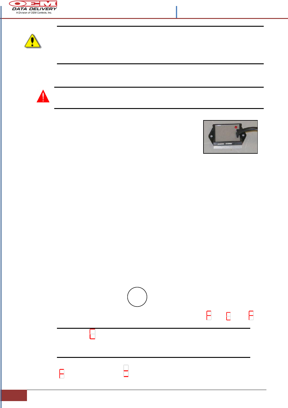
Calibrating the ST-550
Step 1: Start the engine and keep it idling. Once the engine is warmed:
Step 2: Press & Hold the Wake button on Service Tracker. (10 to 15
seconds).
“Window Box Eye” display will cycle from to to
Note: If is not visible on the display during calibration,
check the wire connections to the Vibration Sensor or to
the vehicle alternator and ground.
Otherwise:
Once the disappears, two (2) bars should display in the “Window Box
Eye”.
Contents –STIB 22549 Rev. A
| Confidential and Proprietary, Property of OEM Data Delivery a Division of OEM Controls, Inc |
Section 2
11
Rev the engine. Three (3) bars will display in the Window Box Eye.
Bring the engine back to the idle position, two (2) bars will display.
The ST-550 will now start generating run logs.
Upon Completion
1. Observe the Radio Service Tracker (ST-550)
2. If the alert light flashes on a one second interval, then it is counting hours.
3. If the alert light flashes on a three second interval, then it is Not counting
hours. This indicates that the ST-103 Vibration Sensor is incorrectly
positioned or not functioning.
4. If the bars do not change from two (2) bars to three (3), move the Vibration
Sensor until they display.
5. To obtain Idle and Work Logs, if a Vibration Sensor is Not used, a pulsed
output from the alternator is required.
Note: If alternator does not have a pulsed (RPM) output, the ST-550
display will cycle to to (No pulses) to again.
In this case there will be a Run Log generated.
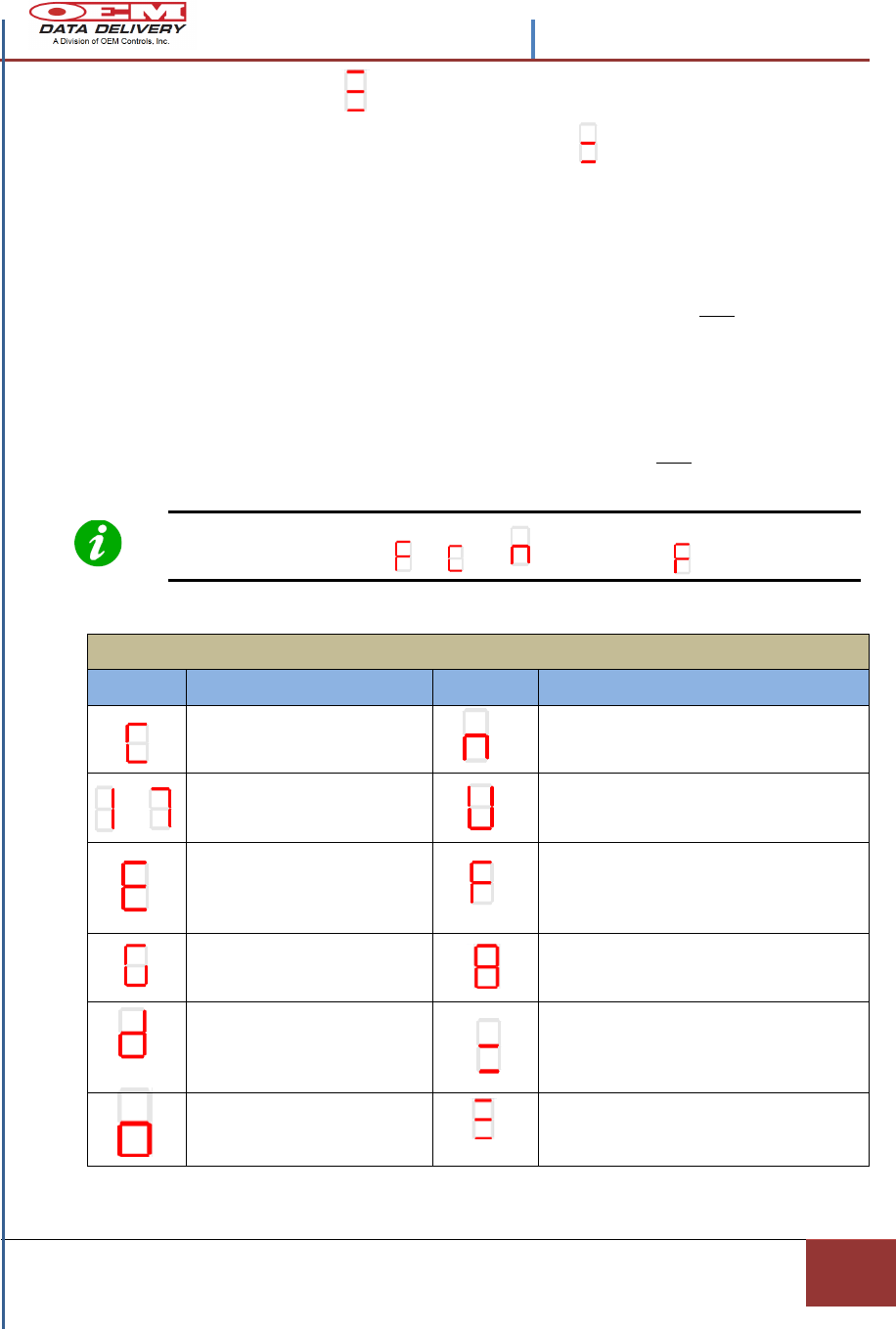
Window Box Displays with Functions
Display
Definition
Display
Definition
CALIBRATION WHEN F1 IS
DEPRESSED FOR (10)
SECONDS
NO PULSES DETECTED
NO IDLE/WORK LOGS TRACKED
to
SERVICE ALARMS DUE,
TURNED OFF BY DEFAULT
UN-CALIBRATED – IGNITION ON
PERFORM CALIBRATION STEPS LISTED
ABOVE.
GPRS CELLULAR ERROR
(NOT NETWORKED)
FUEL MODE – CHANNEL 2 OPERATING
FREQUENCY – 2410 MHZ WHEN “F1”
IS DEPRESSED FOR ABOUT 3
SECONDS
GPS ERROR-NO POWER, A
MALFUNCTION, NO
LOCATION
RADIO/SERIAL DOWNLOADER – RADIO
OPERATING CHANNEL 6
ENTERING DIAGNOSTIC
MODE - ACTIVE AFTER UNIT
IS CALIBRATED- THEN
ERROR CODES DISPLAYED
ENGINE IDLING - CALIBRATION
COMPLETE
GPS OR GPRS
COMMUNICATION STATUS
IS GOOD
ENGINE WORKING - CALIBRATION
COMPLETE
Figure 10.- Seven Segment display
Contents -STIB 22549 Rev. A
12
Section 2 | Installation Procedures
Trouble Shooting after the Installation of ST-550 W/O a
Vibration Sensor
1. If the motor is OFF, and Master Switch is ON and there is a fast-pulse** -
check the Yellow wire connection point. Verify the voltage between the
YELLOW and GREEN wire is less than (6) VDC.
2. If the motor is ON, and Master Switch is ON, and there is a slow-pulse* -
check the Yellow or Green wire connections for breaks.
If the motor is OFF, and the Master Switch is OFF, and there is fast-pulse**
- separate the Green and Black wires. Connect the Green wire to a chassis
ground.
3. If the Service Tracker will not turn on or wake, check the Red and Black
wires for breaks and correct installation. Check for fuse failure at the Red
Wire attachment point to the battery. Using a multi-meter check for 12 or
24v across the Red and Black wires.
4. Important: In using an external battery to “jump” power into the system
and with the coils frame grounded, be sure to connect the external battery
negative to the frame of the vehicle being jumped. This is to keep the
external battery ground and the vehicle frame at the same ground potential.
Pass or Fail Counting Hours Test
Observe the ST-550 at Turn ON
If the alert light flashes, - on a one (1) second interval, then it is
counting hours.
If the alert light flashes, - on a (3) three second interval, then it is NOT
counting hours.
** Fast Pulse - : LED flashes once every one (1) seconds
* Slow Pulse - : LED flashes once every three (3) seconds
Figure 11.- ST-550 Fast and Slow Pulse Display
Observe LED Flashes;
at the bottom right corner
of the “Window box eye”
cube.
Contents –STIB 22549 Rev. A
| Confidential and Proprietary, Property of OEM Data Delivery a Division of OEM Controls, Inc|
Section 2
13
Setting the ST-550 Radio Program
Record the following information:
1. CMH- Cumulative Machine Hours.
2. Service tags (if applicable)
Starting the
Radio Program
on the
Supporting PDA
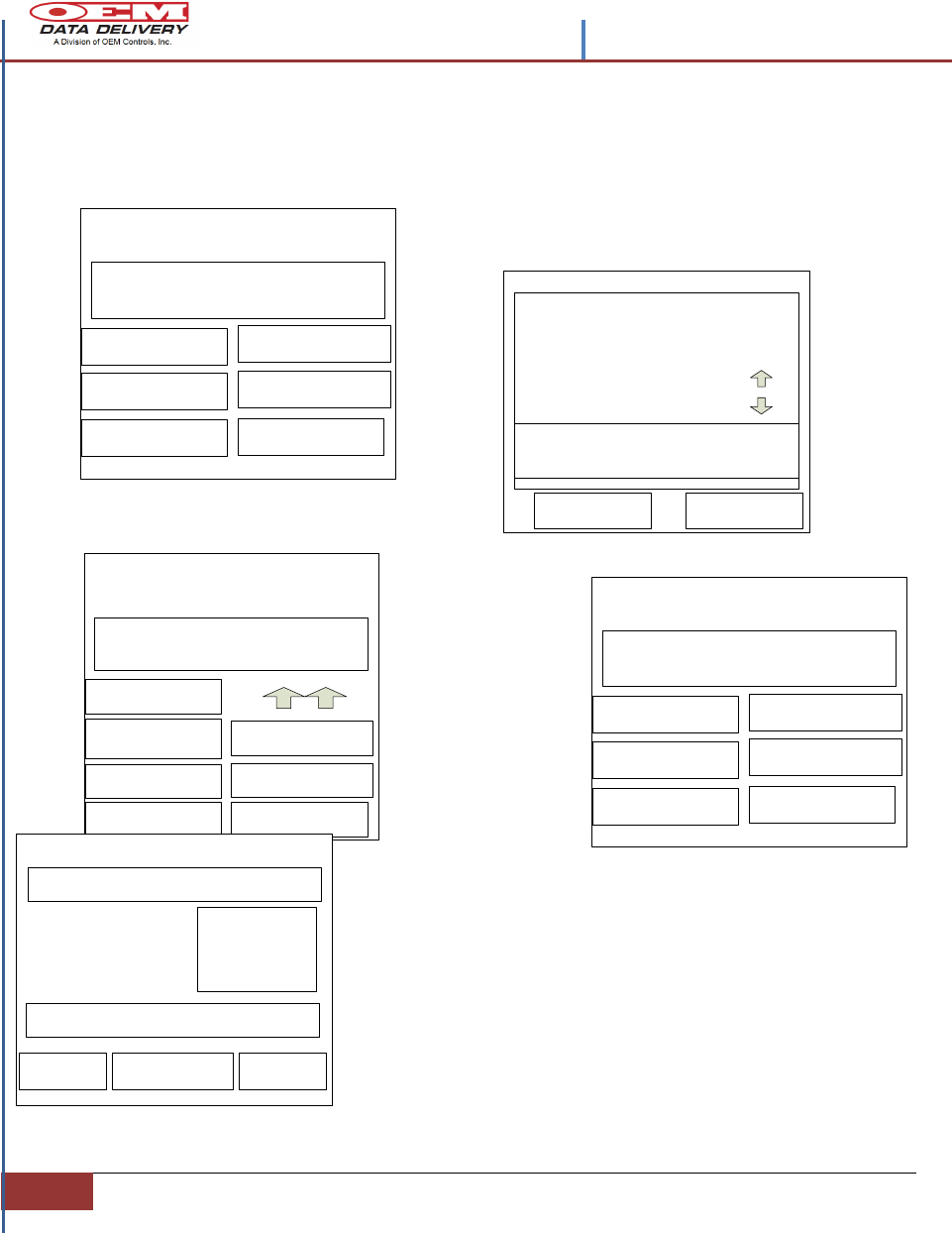
Figure 12.- Setting the ST-550 Radio Tracker Program
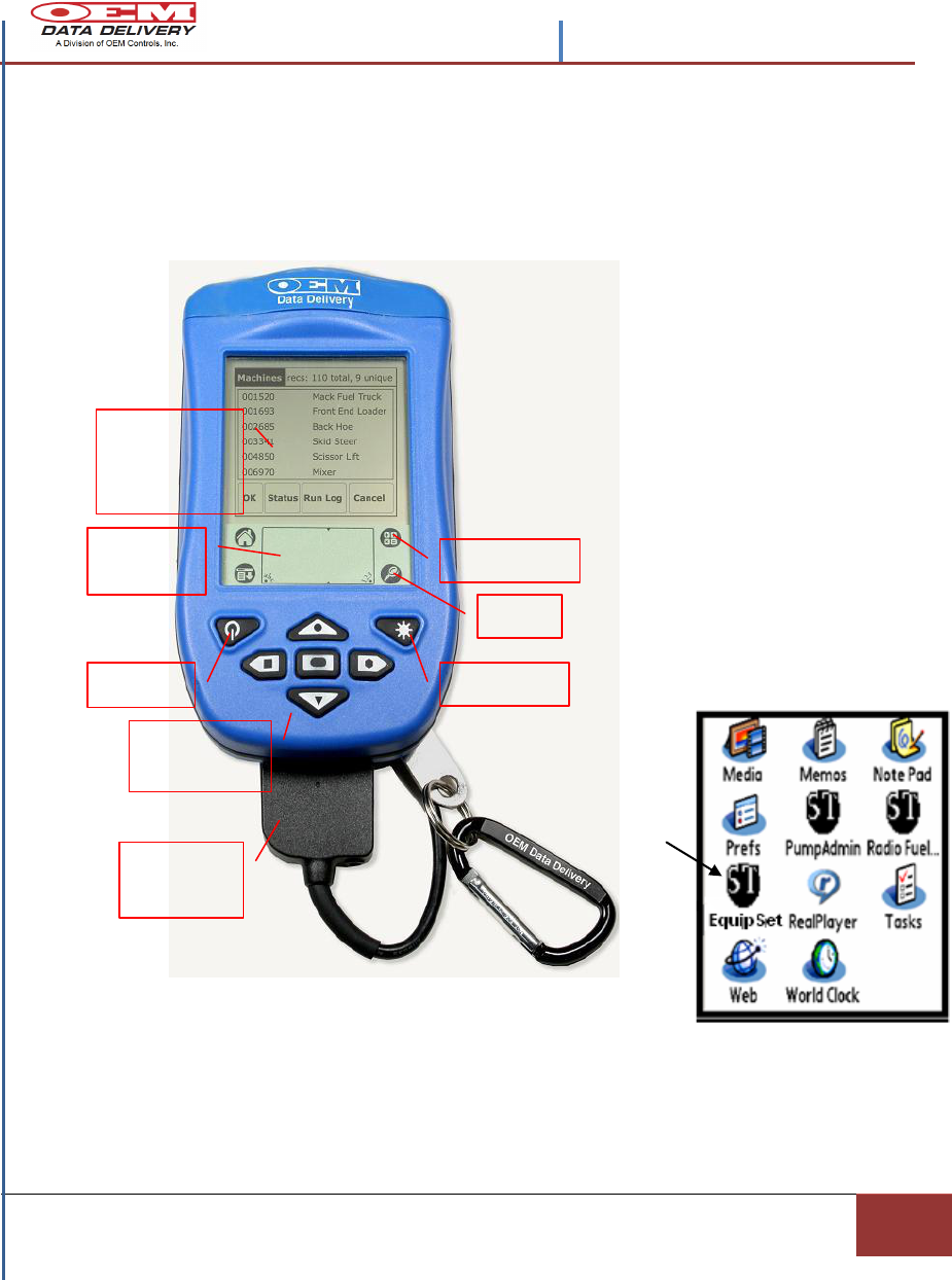
Step 1. Plug in the Primary Antenna
to the PDA.
Step 2. On the PDA press the Power
Button
Step 3. Tap on Radio Tracker Icon,
for the List of Programs.
Power
Direction
Arrows
Touch
Sensitive
Screen
Calculator
Find
Backlight
Graffiti
Pad
Primary
Antenna
3. Serial number of this ST-550.
4. Equipment number.
Contents -STIB 22549 Rev. A
14
Section 2 | Installation Procedures
Step 4. Tap Equipment Set Up icon from the list of programs.
Step 5. When the Load screen launches,
Tap the Radio Box to be sure the PDA is set
on Channel 2.
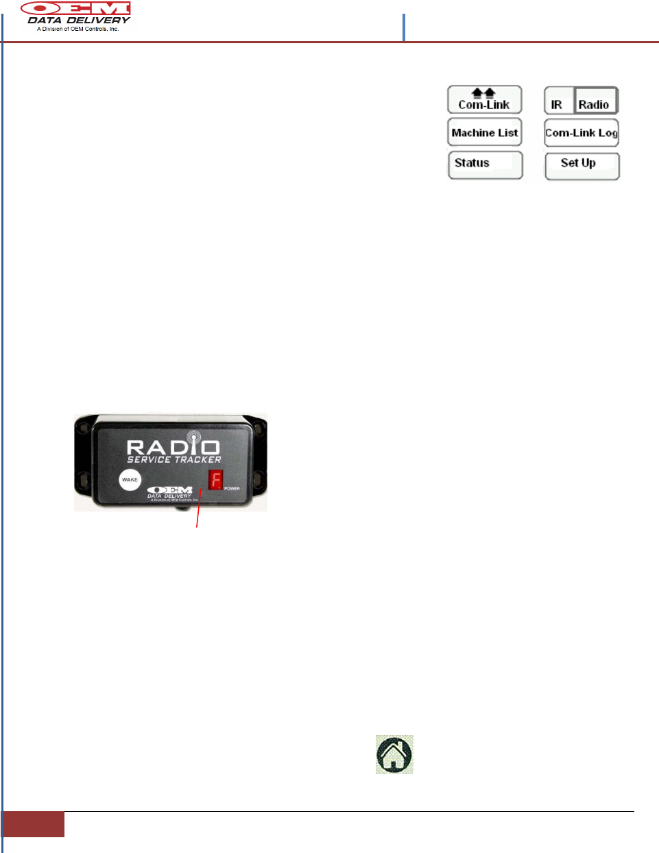
Selecting a Channel for Service Tracker
To use the Radio Com-Link Program with the (ST-550) Service Tracker: Set the
Service Tracker on Channel 2 by holding down the WAKE button for about (5)
five seconds.
On the PDA press the Com-Link button. Once communication is complete
Polling will disappear and the PDA will beep once.
Now that the communication is in place, the Service Tracker can accept program
loading from the PDA. The following steps are required for a first time schedule
loading.
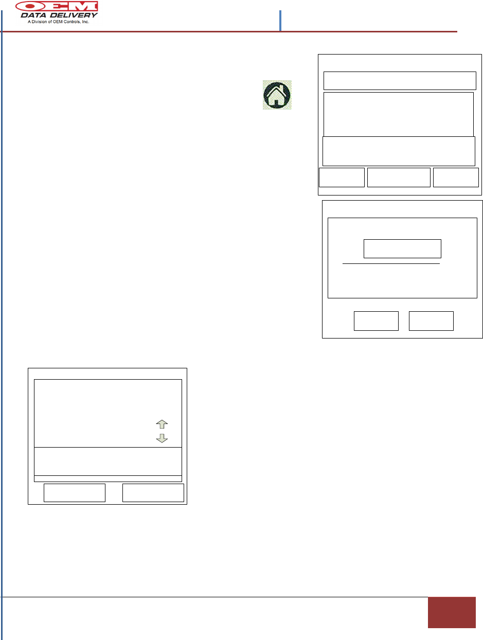
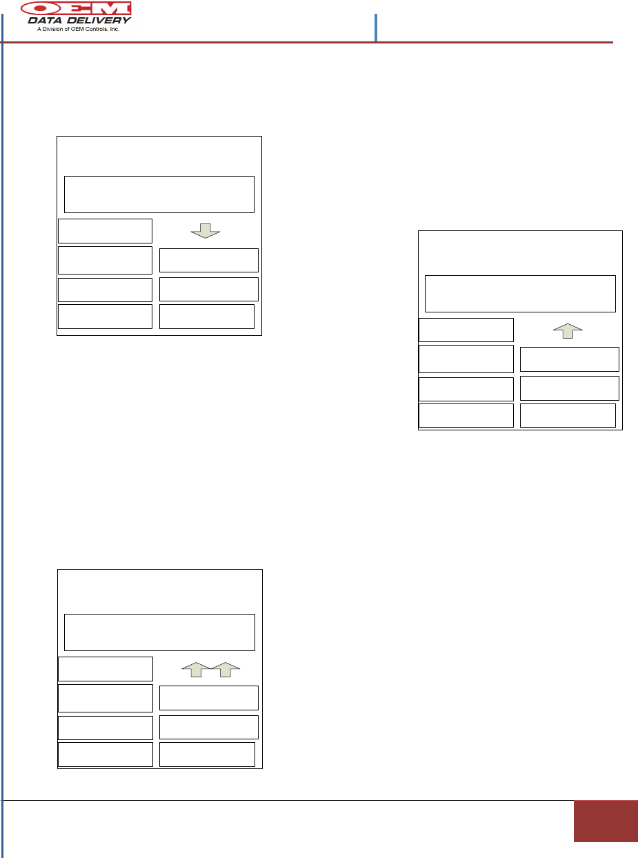
Loading a New Profile
To add a Profile
With power on the PDA tap the House icon.
and then select the Equip Setup icon.
Channel 1: Is the default channel for Service Tracker and
is used for most polling.
Channel 2: Is used for the Service Tracker Set-up and
Com-link. Channel 2 Is only used for polling when the
user is trying ascertain what is in Channel 2.
Note: If the Service Tracker is set on Channel 2 and
does not connect with a primary antenna, it will
return to Channel 1 after (15) fifteen seconds.
The Service Tracker is in CH. 2 when the Alert
Light starts blinking quickly and “F” is displaying
in the “Window Eye”.
Alert Light
Contents –STIB 22549 Rev. A
| Confidential and Proprietary, Property of OEM Data Delivery a Division of OEM Controls, Inc|
Section 2
15
Edit Profile
OK KEYBOARD CANCEL
Tag Edit
OK CANCEL
GREASE
DESC: Actual Scheduled
New Equipment#
Ok CANCEL MEMO
Cumulative Machine Hours ----
-------R
-------R
-------R
-------R
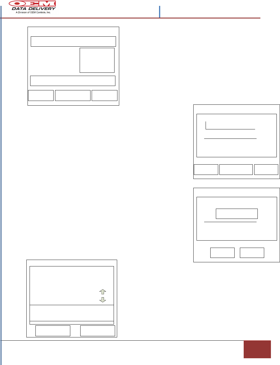
Step 1. From the Load Screen tap the Set Up
box, now tap New Profile.
Tap in the Equipment # dotted area, and see the
Master List of all equipment stored on the PDA.
Tap Edit and launch the Profile List Modify
screen and then tap New.
Figure 12.- Loading a New Profile Screen
The Edit Profile screen will launch. Tap New, now tap
Keyboard and tap in the new description. For any
numbers associated with the description entered, tap the
abc-123 graffiti pad, and tap in numbers and characters
that identify this entry. When the complete description is
entered tap Done, then Ok. The new Equipment # will
appear in the Profile List screen.
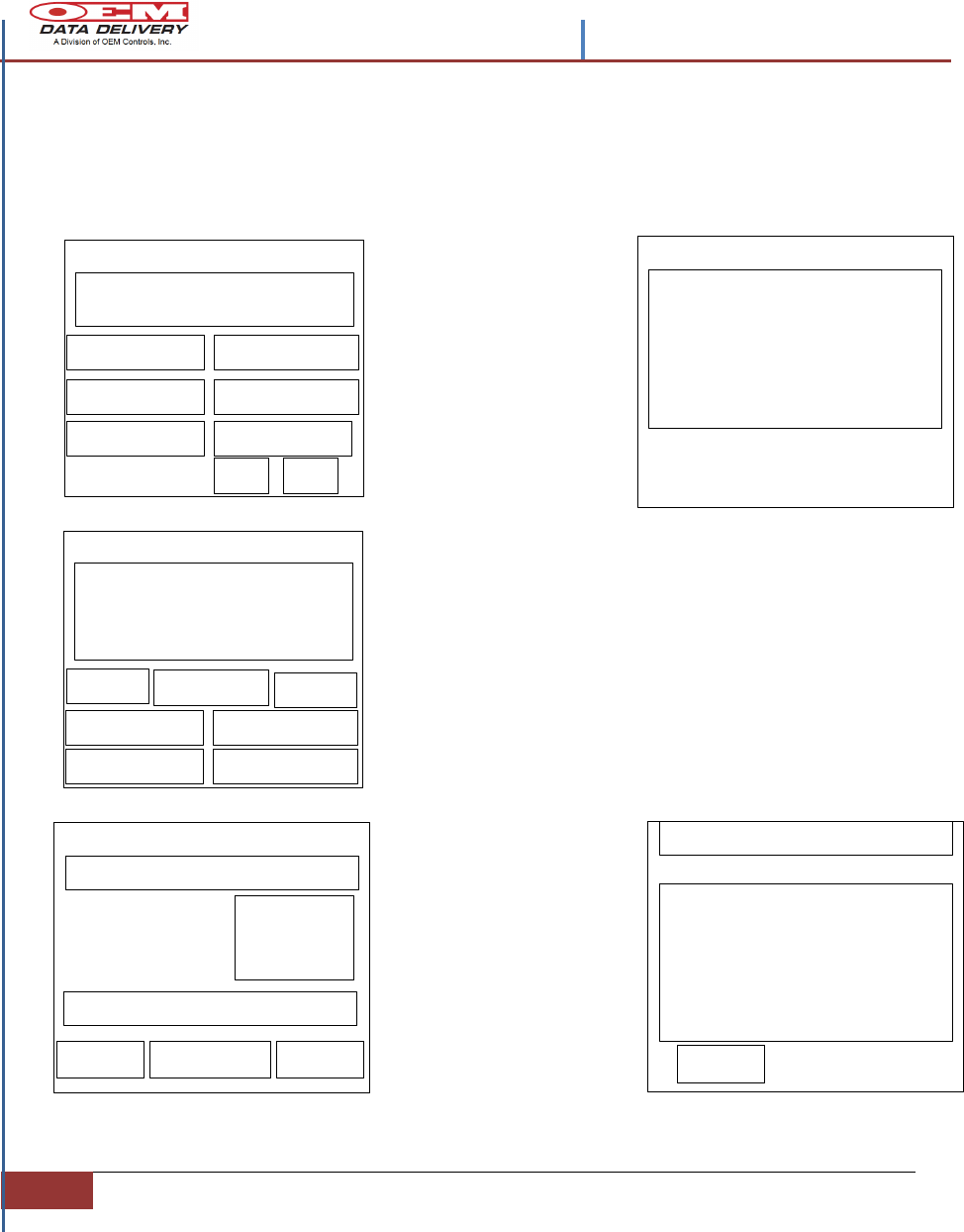
Step 2. To add a Desc: Record tap the blank record box
under this heading.
This will launch the Tag Edit screen. On the Tag Edit
screen enter a service description, such as Oil, Hydraulic
Fluid, by tapping the abc-123 alpha numeric’s, in the
lower corners of the graffiti pad and tapping the
description in the keyboards that appear. When complete
tap OK, to save the description on the new screen.
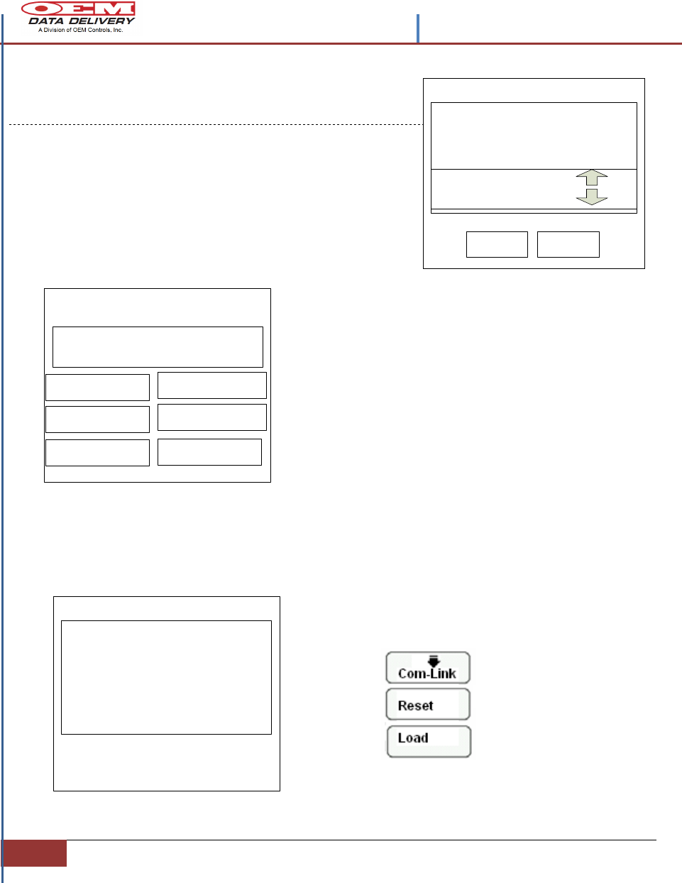
Step 3. To add the Actual Hours or Schedule times, for
this equipment number, tap the box where this
information is shown. Doing this for Actual Hours will
launch the Actual Hours Edit screen.
On the Actual Hours Edit screen, tap the up or
down arrows to increase or decrease the hours
displayed. Tap OK for the hours to appear on
the New Profile Screen for this equipment
number.
Step 4. To add Schedule times, tap the R box,
in the New Profile Screen, (See Figure 12).
This will launch the Reset screen.
Actual Hours Edit
OK
MACHINE
S/N
PERIODIC SERVICE #1
Up
Down
NEW ACTUAL HOURS -0
CANCEL
Contents -STIB 22549 Rev. A
16
Section 2 | Installation Procedures
When data is transferring, observe the “Window Box” on the ST-550 and see the
rotating LED segments. While the transfer is in progress the Polling screen will
appear. When the transfer is complete the polling screen will show a (1) in the
Captured box of the screen. Verifying the transfer is complete to the Service
Tracker.
Machine: Excavator
Equip# 123623
RESET
IR [ RADIO
LOAD
PROFILE LIST
COM-LINK
NEW PROFILE
Last Com-Link on 10/04/2010
Please Wait
0
Polls Captured
Polling
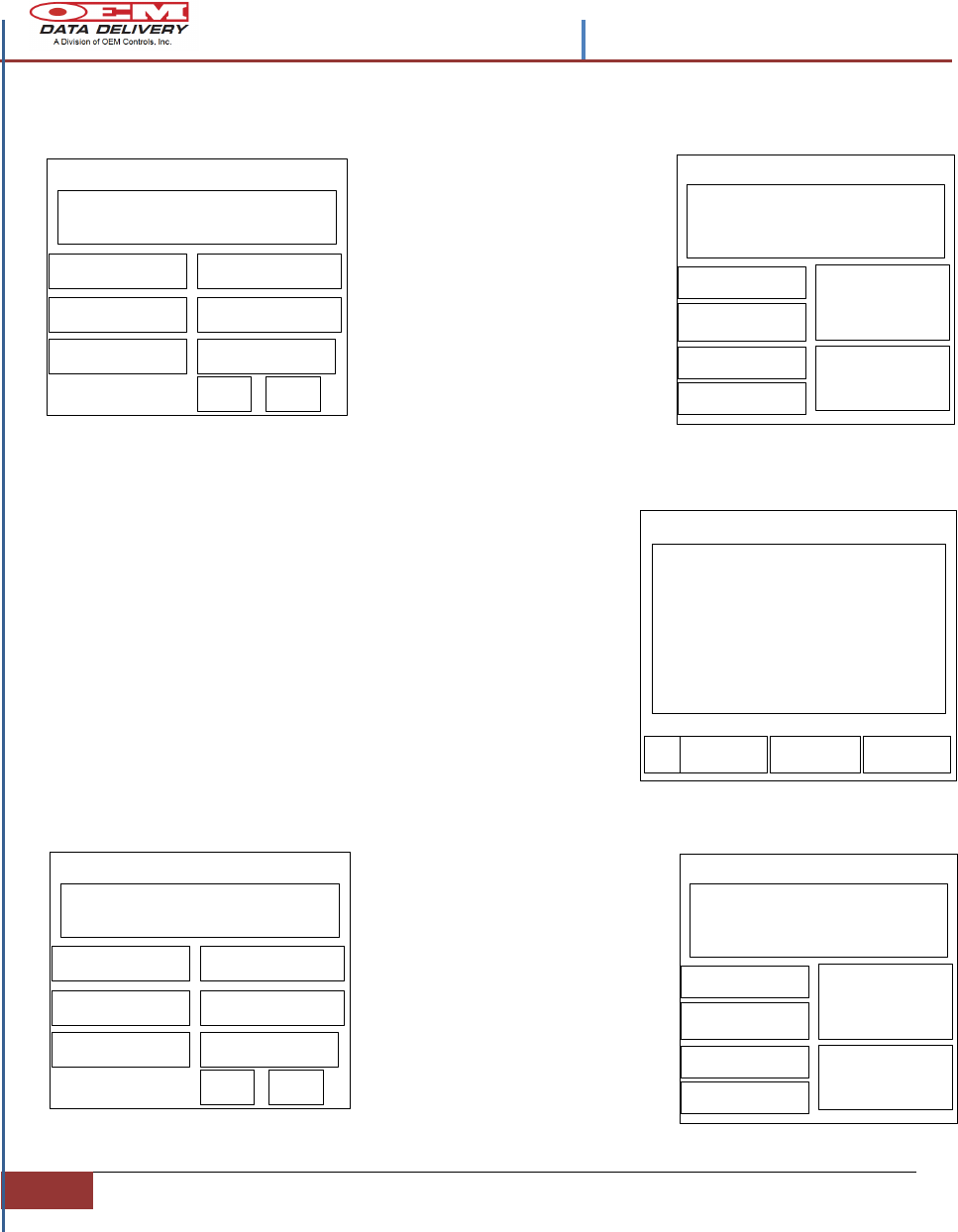
Tap the up or down arrows to increase or
decrease the scheduled hours for service. Tap Ok
for the time to appear next to the R box for this
equipment number.
To enter a start point for Cumulative Machine
Hours, tap on the line to the right of Cumulative
Machine Hours (see Figure 12). When a blinking
cursor is present; tap the abc-123 corners in the
graffiti keypad and enter the number amounts.
Then tap Ok and see the Write Warning
message appear.
The Write Warning message tells the user that any
old information will be overwritten.
Tap Ok and the Set Up screen will launch with a
Com-Link button visible, prompting a data transfer
to the Service Tracker ST-550.
Step 5. To load the new profile into the ST-550,
press and hold the Wake button on the Service
Tracker until it switches to Channel 2, (See the “F”
in the “Window Box”). Tap the Com-Link button to
start the data transfer to the ST-550.
Step 6. The Set Up screen will launch with
the Com-Link arrow pointing down. The
new transfer is complete.
Set Up
SELECT EQ#
ST7-550 Demo Record-> 1
1234 EA
Service Alerts
RETURN ALERTS VIEW
Machine:
S/N
Reset Actual Time
Reset
Ok CANCEL
Change Schedule ------
Contents –STIB 22549 Rev. A
| Confidential and Proprietary, Property of OEM Data Delivery a Division of OEM Controls, Inc|
Section 2
17
Tag Edit
OK CANCEL
GREASE
Desc: Record 1 Actual Sched
Edit Equip# ST7-550
Ok CANCEL MEMO
Cumulative Machine Hours: 14
Timeout: 5
Grease 500 --50--R
Oil 250 --50--R
Transmission 100 --50--R
Hydraulic 50 --50--R
Editing a Profile
To Edit an existing Profile
With power on the PDA tap the House icon
and select the Equip Setup icon.
See the Load screen and tap the Set Up box. When
the Set Up screen appears, tap the Profile List box.
Step 1. From the Profile List tap the Equipment (#)
number you wish to edit. Tap the Edit box and the
edit profile screen will launch.
Step 2. To change or add a Desc: Record tap an
existing or blank record box.
This will launch the Tag Edit screen. On the Tag Edit
screen enter
or change a service description, such as Oil, Hydraulic
Fluid. Tap Ok for it to appear on a new Edit screen.
Step 3. To change the Actual Hours or Schedule
times, for this equipment number, tap the box where this
information is displayed. Doing this for Actual Hours will
launch the Tag Edit screen.
On the Actual Hours Edit screen, tap the up or down
arrows to increase or decrease the hours displayed. Tap
OK for the hours to appear on the new profile screen for
this equipment number.
To enter or change the number of hours that should
occur between each servicing, tap the R box in the Edit
Equipment # screen.
The Reset screen will appear, tap the up or down arrows
next to Change Schedule line to increase or decrease
the hours displayed.
Tap Ok for the hours to appear on the new profile screen
for this equipment number.
Step 4. The Edit screen will also show the Cumulative Machine Hours (CMH) by tapping
the number line on the right side of the CMH. Change or add numbers, by using the abc-
123 corners on the graffiti pad of the PDA. Enter or change the total hours and tap Ok.
The CMH total will now appear on the new screen.
Enter the Timeout value in the timeout section of the Edit Field, by tapping the number
line and using the graffiti pad enter or change the number value.
Actual Hours Edit
OK
MACHINE
S/N
PERIODIC SERVICE #1
Up
Down
NEW ACTUAL HOURS -0
CANCEL
Contents -STIB 22549 Rev. A
18
Section 2 | Installation Procedures
When data is transferring, observe the “Window Box” on the ST-550 and see the
rotating LED segments. While the transfer is in progress the Polling screen will
appear. When the transfer is complete the polling screen will show a (1) in the
Captured box of the screen.
Please Wait
0
Polls Captured
Polling
Copying a Profile to Another Service
Tracker
This is used when there are (2) two or more identical machines with similar
maintenance schedules in a fleet. The copy function creates a new machine profile
The Timeout value is a settable time period the ST-550 waits, with no activity, before going to
sleep. In the Edit Field, tap the number line. Using the abc-123 corners of the graffiti pad enter
or change the number value. Timeout is measured in hours.
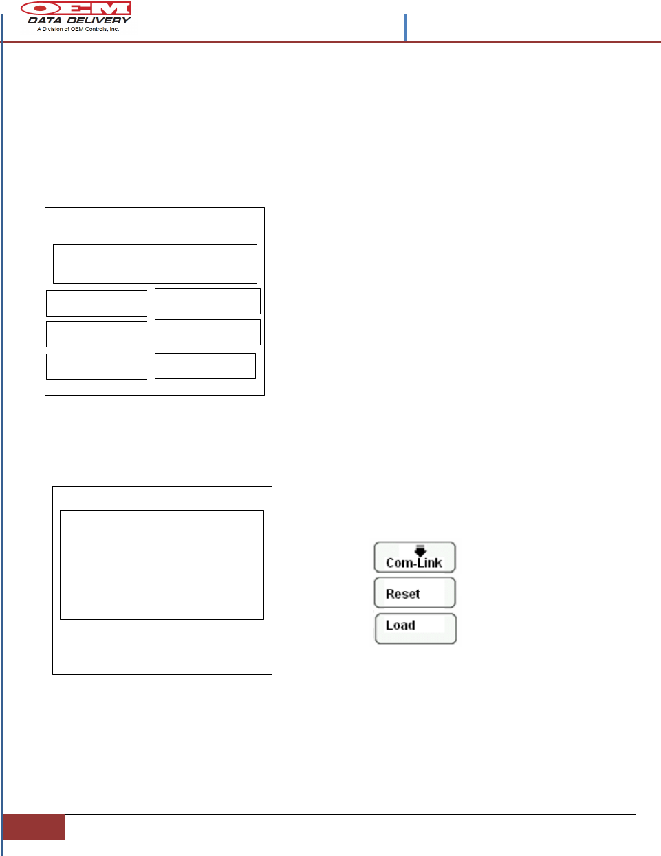
Step 5. Tap on the Memo button to enter some special service instructions, or parts required,
for machine maintenance.
Tap Ok when all changes and additions have been entered for this equipment number.
The Write Warning message tells the user that any
old information will be overwritten.
Tap Ok and the Set Up screen will launch with a
Com-Link button visible prompting a data transfer
to the Service Tracker ST-550.
Step 6. To load the new profile into the ST-550,
press and hold the Wake button on the Service
Tracker until it switches to Channel 2, (See the “F”
in the “Window Box”). Tap the Com-Link button to
start the data transfer to the ST-550.
Step 7. The Set Up screen will launch with
the Com-Link arrow pointing down. The
new transfer is complete
Machine: Excavator
Equip# 123623
RESET
IR [ RADIO
LOAD
PROFILE LIST
COM-LINK
NEW PROFILE
Last Com-Link on 10/04/2010
Set Up

Contents –STIB 22549 Rev. A
| Confidential and Proprietary, Property of OEM Data Delivery a Division of OEM Controls, Inc|
Section 2
19
from the one previously set up. All information from the previous profile is copied to
the new with the exception of the serial number and cumulative machine hours.
Step 1. From the Set Up screen select the Profile List box.
Step 2. From the Profile List screen tap the profile to be copied, then tap the
Copy button and the new screen will appear.
Step 3. Enter the new equipment number, by tapping on the dotted box to the
right of the Equipment number, the Master List will launch. Tap any equipment
number, then, tap the Edit button. The Profile List Modify screen will display.
Step 4. On the Profile List Modify screen, tap the New button and the Edit
Profile screen will show.
Step 5. On the Edit Profile screen enter a serial number unique to this
equipment. Use the abc-123 alpha numeric keyboards from the graffiti pad to
enter this information. Enter a description of this equipment and tap OK.
Step 6. To enter other service tags follow the directions from the Editing a
Profile section. Upload this new equipment profile to the Service Tracker ST-
550, following the directions in Editing a Profile section, steps 5, 6, and 7.
Deleting a Machine Profile
This is used to delete a stored profile on the PDA. Profiles can only be deleted on
the PDA and not the Service Tracker. Profiles on the Service Tracker can only be
overwritten.
Step 1. From the Set Up screen, select the Profile List box.
Step 2. From the Profile List screen, select the profile to be deleted, then, tap
the Delete box. Continue tapping the Delete button until the profile is deleted
from the screen.
Note: Once the Delete button is tapped
the total field will be reduced by one;
but the unique field will remain the
same until all the Com-Link records for
that profile are gone. Each time the
PDA is beamed at the Service Tracker a
record is created within the Com-Link
database. The total field, on the profile
screen displays the total number of
records within the Com-Link database.
The unique field is the total number of
machine profiles within the database.
12623 Excavator
987-654 Dozer
456-897 Dozer
123621 Excavator
EDIT DELETE CANCEL
Profile List: 7 total, 4 unique
COPY
Contents -STIB 22549 Rev. A
20
Section 2 | Installation Procedures
Downloading a Machine Profile
Use this option to download a profile from a Service Tracker for viewing or
modification on the PDA. After the changes to the Profile are made, the
profile can then be uploaded back to the Service Tracker.
Step 1. Start at the Load screen. The load screen is accessed when the
Radio Com-Link software is started at the Set Up screen. Refer to the
Loading a New Profile section.
Step 2. With the PDA at the Set Up screen, point the PDA at the Service
Tracker to be accessed. Tap the Com-Link box to start the download process
of the Service Tracker’s equipment information.
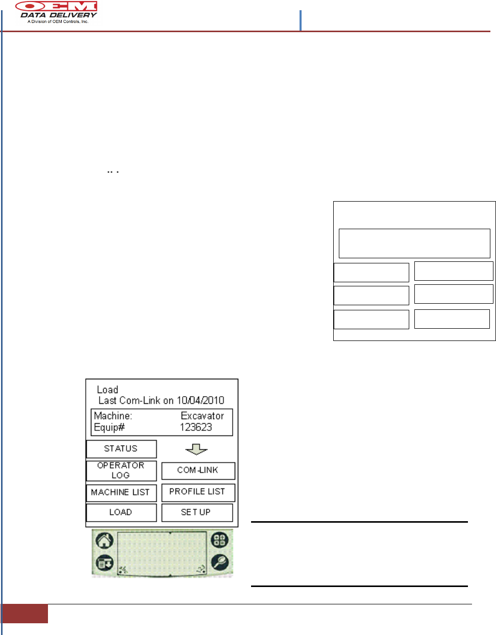
Communicating With the
ST-550
Step 3. When the download is
complete, the PDA will beep once. The
Status screen and Operator logs can
now be viewed. To change any portion,
use the Editing a Profile instructions to
change the profile of this down loaded
equipment number.
From the Load screen find the Com-Link
and the Com-Link Log boxes.
Com-Link button: This box is used to
read service information or upload profile
changes to the Service Tracker.
Com-Link Log button: Displays a list of
records for each the Service Tracker was
beamed. It shows the equipment number,
date, time and hours on the equipment
when the information was beamed.
Note: This log can be transferred to another
PDA by tapping on the beam box of
the Com-Link Log screen and
aligning the PDA’s infrared panels.
Machine: Excavator
Equip# 123623
RESET
IR [ RADIO
LOAD
PROFILE LIST
COM-LINK
NEW PROFILE
Last Com-Link on 10/04/2010
Set Up
Contents –STIB 22549 Rev. A
| Confidential and Proprietary, Property of OEM Data Delivery a Division of OEM Controls, Inc|
Section 2
21
Machine: Excavator
Equip# 123623
OPERATOR
LOG COM-LINK
MACHINE LIST PROFILE LIST
STATUS
SET UP
Last Com-Link on 10/04/2010
Load
LOAD
Machine: Excavator
Equip# 123623
OPERATOR
LOG COM-LINK
MACHINE LIST PROFILE LIST
STATUS
SET UP
Last Com-Link on 10/04/2010
Load
LOAD
Machine: Excavator
Equip# 123623
OPERATOR
LOG COM-LINK
MACHINE LIST PROFILE LIST
STATUS
SET UP
Last Com-Link on 10/04/2010
Load
LOAD
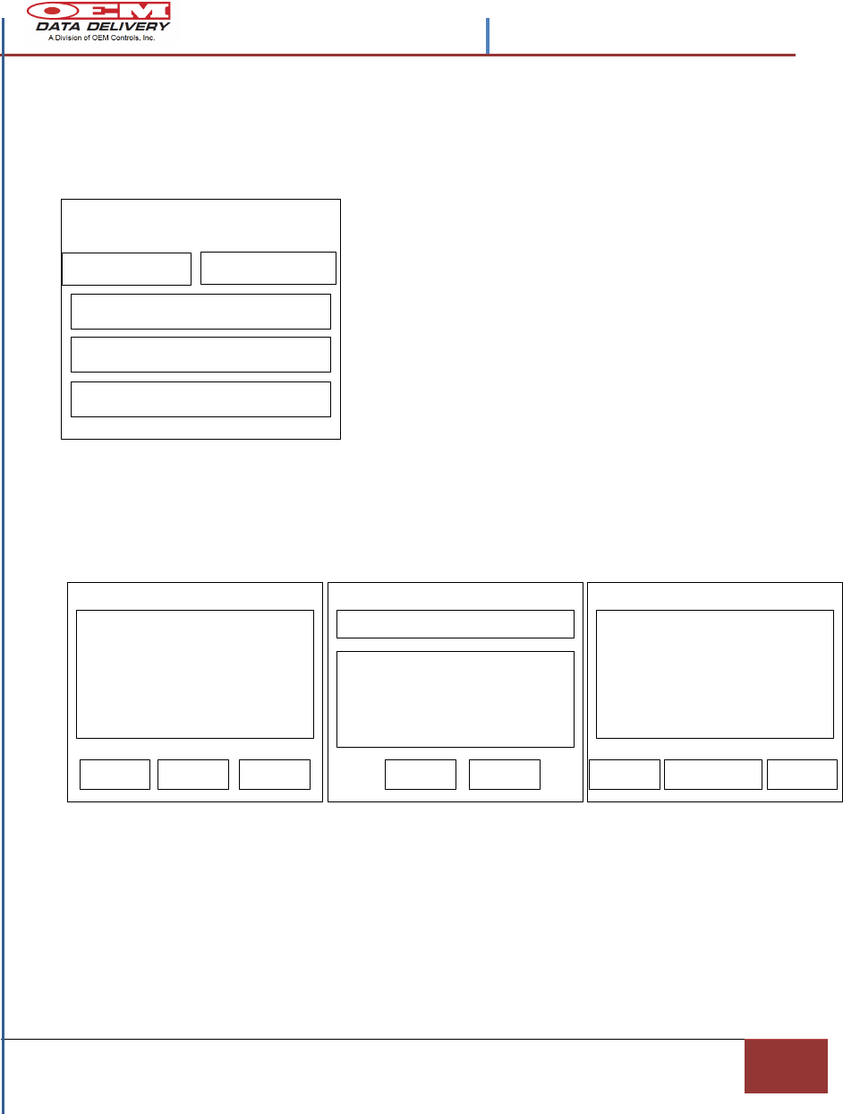
Data Loading Modes
The Down Load Mode: Recognizable by a single
down pointing arrow toward the Com-Link box on
either the Load or Set Up screens. This indicates
that the last action performed was a download from
the Service Tracker.
This indicates that information has been changed in the Status screen.
Changed Information, such as Actual Hours (the hours between servicing for this
equipment number), Reset, (this is used to reset an alarm, if this set to zero no alarms
will occur for this equipment number), or the Scheduled Hours (used in conjunction with
the Reset box to change the scheduled hours), will update the Service Tracker through
the Com-Link software. The Com-Link software will synchronize this changed
information and then update the Service Tracker through the Com-Link box, as noted
by the upward pointing
The Overwrite Mode: Recognizable by the
two up pointing arrows above the Com-Link
box on either the Load or Set Up screens,
indicates that the Com-Link software will
overwrite any profile on the Service Tracker
with the profile as displayed in the Machine
List screen.
The Update
Load Mode:
Recognizable by
a single up
pointing arrow
above the Com-
Link box on
either the Load
or Set Up
screens.
Contents -STIB 22549 Rev. A
22
Section 2 | Installation Procedures
Equip# Desc:
07-31-10-2 073107
07-31-10-17 073107
07-31-10-16 07107
Capture 3/12 DB 3
STATUS RUN LOG ALERTS
POLL CAPTURE
MISSING DONE
DESC: Actual Scheduled
Status Equipment#
Ok CANCEL MEMO
Cumulative Machine Hours ----
-------R
-------R
-------R
-------R
Please Wait
0
Polls Captured
Polling
07-31-10-16 073107
Ok
Buckets
Collecting Data – Polling
From the main PDA menu screen tap EquipHours to download a profile from a
Service Tracker for viewing or modification on the PDA. After the changes to the
Profile are made, the profile can then be uploaded back to the Service Tracker.
Tapping either Poll,
Poll Cont,
Continuous, or Run
Log: the PDA will go to
the polling screen.
“Syncing” will appear
on the PDA. During
this process the PDA is
searching for all
Service Trackers in its
range. This may take a
few moments.
From the Capture screen, scroll down and select and tap
the Service Tracker to view by Equipment Number.
Tap Status on the PDA. This will switch to the Status
Screen, showing the equipment profile. This screen is also
available from the Data and Logs menu. See the selected
number description, actual and scheduled hours for Service
Alerts and the cumulative machine hours (CMH) for the
equipment number selected.
Tap Run Log and the
Buckets screen will
appear. This screen
will display run log
information, or the
work and idle time
times associated with
the equipment
selected.
Tap Ok to return to the
Capture screen.
JOB LOCATION:
Radio Tracker User: MG
POLL CONT
CONTINOUS
DATA & LOGS
RUN LOG
POLL ONCE
RST
Ch 1 Ch 2
The process is complete when the Captured information
appears.

Contents –STIB 22549 Rev. A
| Confidential and Proprietary, Property of OEM Data Delivery a Division of OEM Controls, Inc|
Section 2
23
ST7-550 Demo Record-> 1
1234 EA
Service Alerts
RETURN ALERTS VIEW
Equip# Desc:
07-31-10-2 073107
07-31-10-17 073107
07-31-10-16 07107
Capture 3/12 DB 3
STATUS RUN LOG ALERTS
POLL CAPTURE
MISSING DONE
Equip# Desc:
07-31-10-2 073107
07-31-10-17 073107
07-31-10-16 07107
Capture 3/12 DB 3
STATUS RUN LOG ALERTS
POLL CAPTURE
MISSING DONE
Tap Missing and the Missing List screen will
launch. This screen displays a list of Service
Trackers that have previously been polled but have
not been captured in this round of polling.
Tapping the Poll box; visible from the Capture or
Missing List screen, initiates a cycle through stored
information.
This action overwrites the information on the PDA,
that was previously stored, with the latest polled
data configuration.
Tapping the Capture box; visible from the Capture
or Missing List screen, retains all previous polled
information rather than resets it; as the Poll feature
does. A poll cycle will occur to capture any Service
Trackers that were not detected during the first
round of tracking and this new information will be
added to the existing list.
Tap Alerts and the Service Alerts screen will
appear. This screen notifies the user when a
maintenance function on this equipment
number is required. It will give the option to
service now or later. This Service Tracker will
also indicate a service alert at the LED display
window (see Figure 10).
EQ# Desc
90789 Red truck
ST7-550 Demo Record-> 1
30017 Scraper
99900 Prod ST5-500
Missing List
REMOVE
POLL CAPTURE
REMOVE
Contents -STIB 22549 Rev. A
24
Section 2 | Installation Procedures
Last Com-Link on
Machine: Excavator
Equip# 123623
MACHINE LIST
MAIN RADIO
CAPTURED LOGS
STATUS
Info User: MGreen
ACTION+INFO
Last Com-Link on
Machine: Excavator
Equip# 123623
MACHINE LIST
MAIN RADIO
CAPTURED LOGS
STATUS
Info User: MGreen
ACTION+INFO
07-31-10-16 073107
07-31-10-2 073107
07-31-10-17 073107
07-31-10-16 07107
Vinny 5897
Nick 160H
STATUS RUN LOG ALERTS
: 97 total, 12 unique
Ok
Viewing Equipment Maintenance Schedules
Entering Notes for this Equipment Number
Viewing Equipment Activity
From the Radio Tracker Main
Menu tap Data & Logs and
Launch this Info screen.
Tap Status to view a Machine
Profile (See Monitoring the
Equipment Section).
Tap Machine List to launch
the machines screen. This
screen displays a list of
machines you have stored in
the PDA.
From the Main Menu (above) tap the Data & Logs box, to
launch Info screen (upper right) and tap Action +Info.
From this screen (see right), select the
machine/equipment type record and tap Ok. The info
screen will return; now tap Action +Info again and launch
the note screen for this equipment number. Enter the
pertinent information for this equipment, by selecting the
keyboard or by using the abc graffiti corner keys. Tap Ok
to save.
From the Radio Tracker
Main Menu tap Data & Logs
and Launch this Info screen.
Tap Logs
Tap Captured to view all previously polled and captured
equipment maintenance schedules.
JOB LOCATION:
Radio Tracker User: MG
POLL CONT
CONTINOUS
DATA & LOGS
RUN LOG
POLL ONCE
RST
Ch 1 Ch 2
JOB LOCATION:
Radio Tracker User: MG
POLL CONT
CONTINOUS
DATA & LOGS
RUN LOG
POLL ONCE
RST
Ch 1 Ch 2
Contents –STIB 22549 Rev. A
| Confidential and Proprietary, Property of OEM Data Delivery a Division of OEM Controls, Inc|
Section 2
25
Viewing A+I Notes, History, Com-Link and Service Alerts
records
The following options show current maintenance records of operational field
equipment:
Tap A+I History to launch the A+I History screen.
This screen displays all the note activity that has
been entered through the A+I feature as well as all
other activity information.
Tap A+I Notes to launch the notes screen. This
screen displays all the note activity that has been
entered through this activity.
Tap Service Alerts to launch the Service Alerts.
This screen displays the service alerts for all the
pieces of equipment stored on the PDA.
Tap Com-Link to launch the Com-Link Log screen. This screen displays a list of
Service Trackers that have been com-linked most recently. From this list, select any
Service Tracker, (within range), and view its status by tapping Status box.
Tap Return to launch the Data & Logs screen again. From the Data & Logs main
screen tap Radio to return to the Main Menu.
COMLINK
Logs
A+I HISTORY
A+I NOTES
SERVICE ALERTS
RETURN
SELECT EQ#
ST7-550 Demo Record-> 1
1234 EA
RETURN ALERTS VIEW
12623 Excavator
6/12/2010 13:00 hours 5903
12623 Excavator
6/12/2010 10:26 hours 7563
Com-Link Log
BEAM CANCELSTATUS
ST7-550 Demo Record-> 1
1234 EA
Service Alerts
RETURN ALERTS VIEW
User Date Hours Notes
Notes record 0 of 0
RETURN VIEW
Contents -STIB 22549 Rev. A
26
Section 2 | Installation Procedures
Machine: Excavator
Equip# 123623
OPERATOR
LOG COM-LINK
MACHINE LIST PROFILE LIST
STATUS
SET UP
Last Com-Link on 10/04/2010
Load
LOAD
DESC: Actual Scheduled
New Equipment#
Ok CANCEL MEMO
Cumulative Machine Hours ----
-------R
-------R
-------R
-------R
NOTES:
Actual Hours Edit
OK
MACHINE
S/N
PERIODIC SERVICE #1
Up
Down
NEW ACTUAL HOURS -0
CANCEL
Machine: Excavator
Equip# 123623
RESET
IR [ RADIO
LOAD
PROFILE LIST
COM-LINK
NEW PROFILE
Last Com-Link on 10/04/2010
Set Up
Z
Machine: Excavator
Equip# 123623
OPERATOR
LOG
COM-LINK
MACHINE LIST
PROFILE LIST
STATUS
SET UP
Last Com-Link on 10/04/2010
LOAD

27
Section 3 | Confidential and Proprietary, Property of OEM Data Delivery a Division of OEM
Controls,
Section 3
Index
7
7 Segment Display, 12, 13
A
A+I Notes, 27
Actual Hours, 17
Antenna, 4
C
Calibration., 12
Capture Box, 25
CH. 1, 4
CH. 2, 4
Com-Link, 18
Cumulative Machine Hours, 1
E
Edit Profile, 21
F
Fast Pulse., 14
G
GoPOD, 1
graffiti keypad, 17
I
Installation Procedures, 9
IrDA communication., 1
M
Machine List, 26
Motor Run Voltage., 10
O
Operating Temperature 4
Operating voltage, 4
Overview of the ST-550, 1
P
Polling, 25
Profile, 16
Profile Download, 22
R
Radio, 4
S
Service Alerts, 27
Service Tracker serial number, 9
Set Up, 22
Slow Pulse., 14
ST-103., 12
Status., 26
T
tag edit., 19
V
Vibration Record Box., 19
Vibration Sensor ST-103., 2, 10
W
Window Box, 20
Window Box Eye., 12