OKIN Refined Electric Technology JLDK-18-4 Wireless remote handset User Manual x
OKIN Refined Electric Technology Co., Ltd. Wireless remote handset x
UserManual.wiki
>
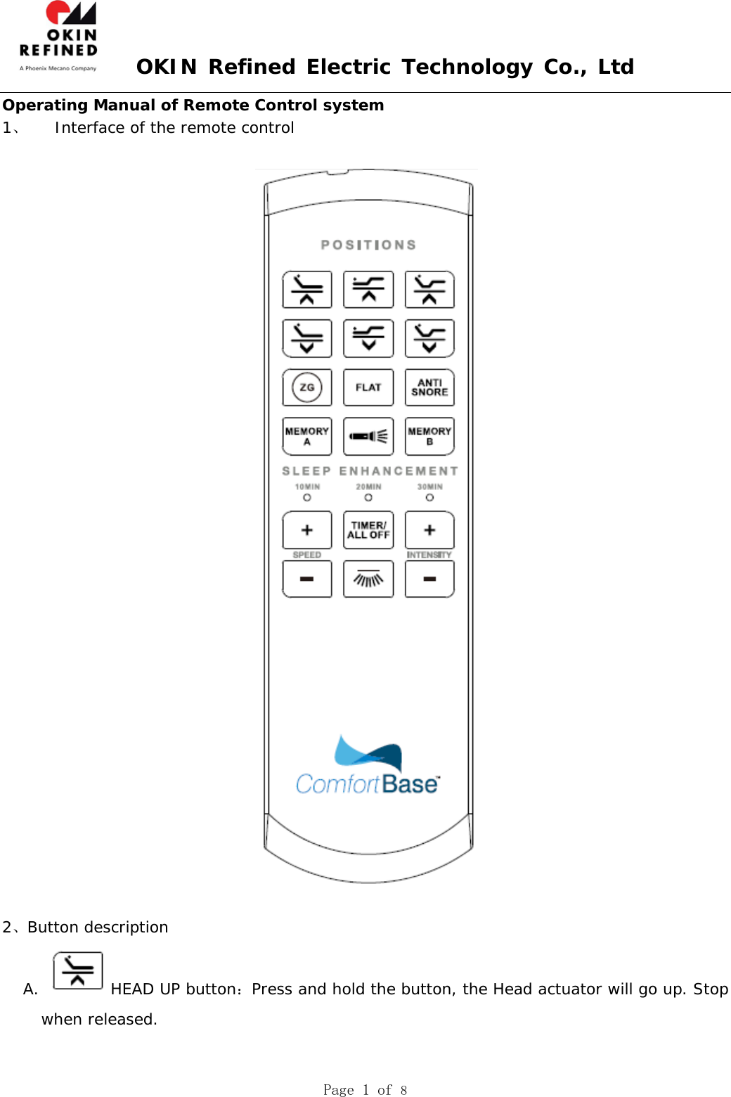
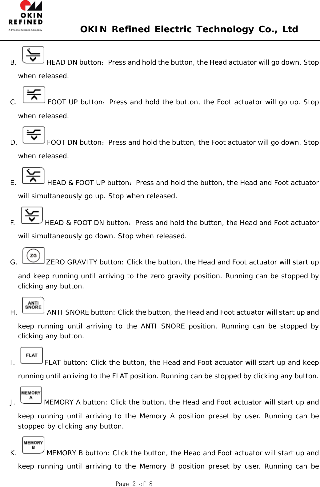
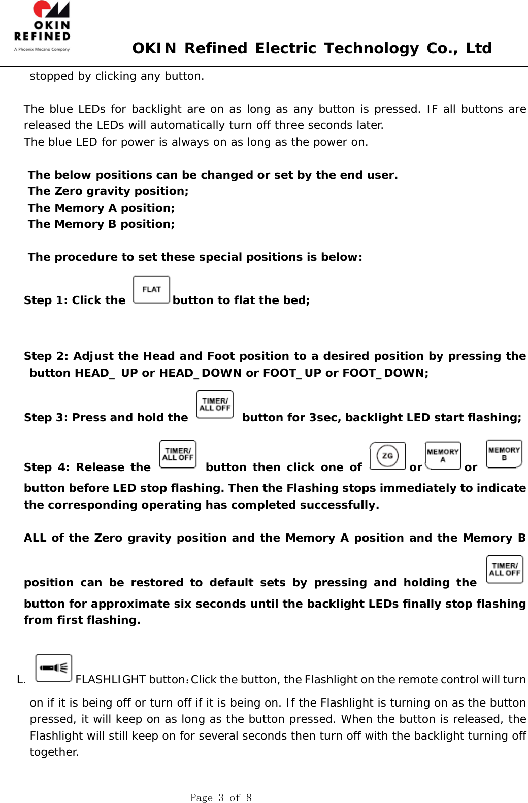
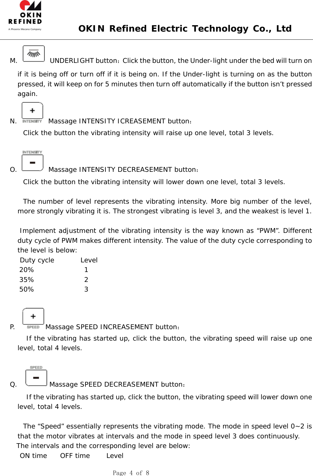
OKIN Refined Electric Technology
>
JLDK 18 4 User Manual
Users Manual
Navigation menu
Upload a User Manual
Namespaces
Wiki Guide
HTML
PDF
Info
Views
User Manual
Discussion / Help
Navigation