OKIN Refined Electric Technology JLDK4218 Remote Control User Manual User manual
OKIN Refined Electric Technology Co., Ltd. Remote Control User manual
User Manual

OKIN Refined Electric Technology Co., Ltd
Page 1 of
5
Operating Manual of Remote Control system
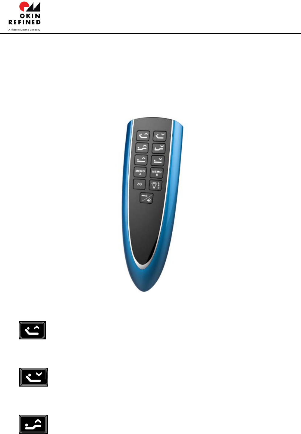
1、 Interface of the remote control
2、Button description
A. HEAD UP button:Press and hold the button, the Head actuatorwill go up. Stop
when released.
B. HEAD DN button:Press and hold the button, the Head actuator will go down. Stop
when released.
C. FOOT UP button:Press and hold the button, the Foot actuator will go up. Stop
JLDK.42.18.14 UserManual

OKIN Refined Electric Technology Co.,Ltd
Page 2 of 5
when released.
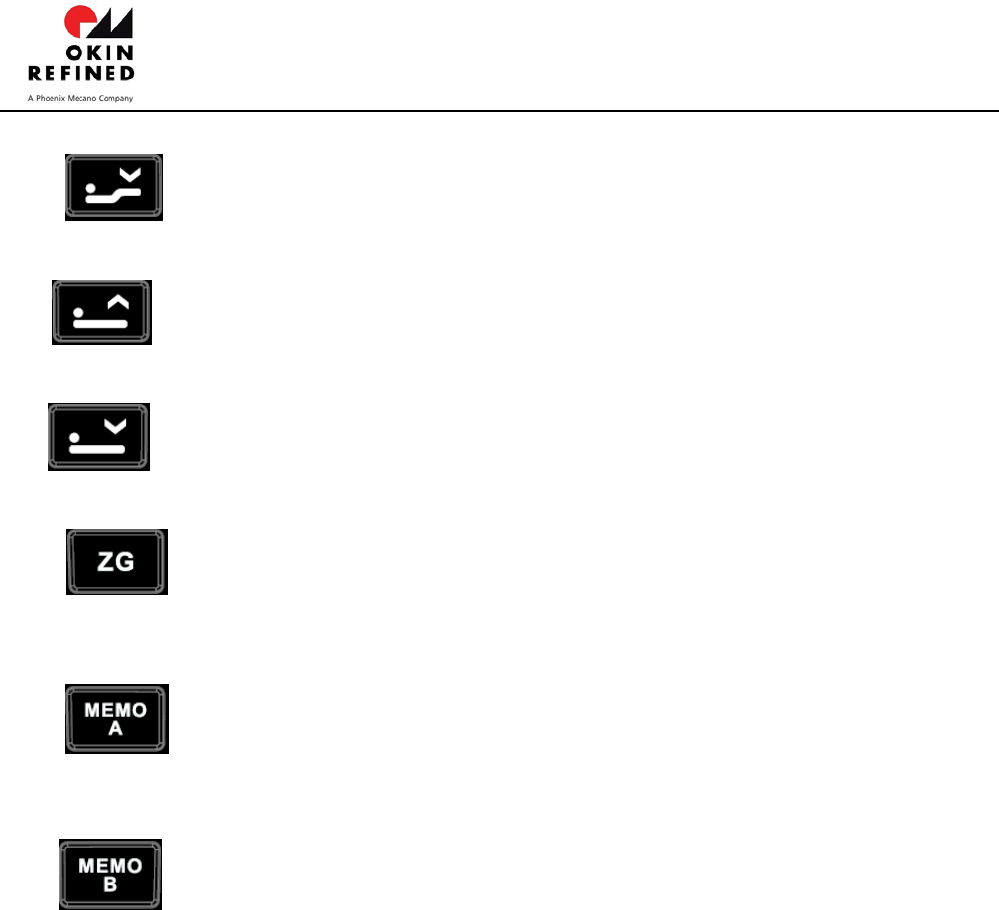
D. FOOT DN button:Press and hold the button, the Foot actuator will go down. Stop
when released.
E. LIFT UP button:Press and hold the button, the Lift actuator will simultaneously go
up. Stop when released.
F. LIFT DN button:Press and hold the button, the Lift actuator will simultaneously go
down. Stop when released.
G. ZERO GRAVITY button: Click the button, the Head and Foot actuator will start up
and keep running until arriving to the zero gravity position. Running can be stopped by
clicking any button.
H. MEMORY Abutton: Click the button, the Head and Foot actuator will start up and
keep running until arriving to the Memory A position preset by user. Running can be
stopped by clicking any button.
I. MEMORY Bbutton: Click the button, the Head and Foot actuator will start up and
keep running until arriving to the Memory B position preset by user. Running can be
stopped by clicking any button.
The white LEDs for backlight are on as long as any button is pressed. IF all buttons are
released the LEDs will automatically turn off three seconds later.
The blue LED for power is always on as long as the power on.
The below positions can be changed or set by the end user.
The Zero gravity position;
The Memory A position;
The Memory B position;

OKIN Refined Electric Technology Co.,Ltd
Page 3 of 5
The procedure to set these special positions is below:
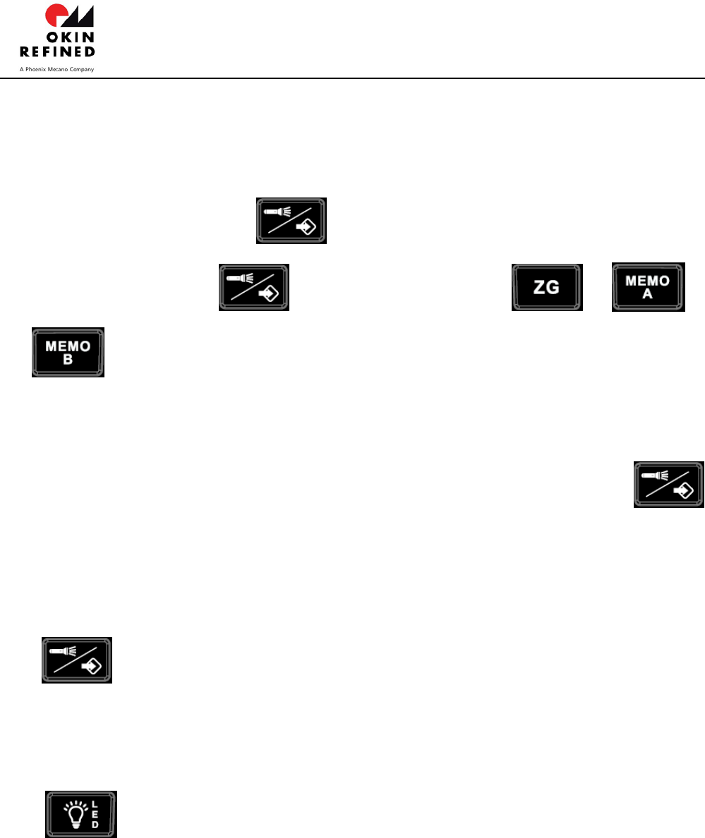
Step 1: Adjust the Head and Foot position or Lift position to a desired position by
pressing the button HEAD_ UP or HEAD_DOWN or FOOT_UP or FOOT_DOWNor
LIFT_UP or LIFT_DOWN;
Step 2: Press and hold the button for 3sec, backlight LED start flashing;
Step 3: Release the button then click one of or or
button before LED stop flashing. Then the Flashing stops immediately to
indicate the corresponding operating has completed successfully.
ALL of the Zero gravity position and the Memory A positionand the Memory B
position can be restored to default sets by pressing and holding the
button for approximate six seconds until the backlight LEDs finally stop
flashingfrom first flashing.
Only Memory A can store Lift position.
J. FLASHLIGHT button:Click the button, the Flashlight on the remote control will
turn on if it is being off or turn off if it is being on.If the Flashlight is turning on as the
button pressed, it will keep on as long as the button pressed. When the button is released,
the Flashlight will still keep on for several seconds then turn off with the backlight turning
off together.
K. UNDERLIGHT button:Click the button, the Under-light under the bed will turn on
if it is being off or turn off if it is being on.If the Under-light is turning on as the button
pressed, it will keep on for 5 minutes then turn off automatically if the button isn’t pressed
again.
3、Wireless pairing operation
Step1: Push the DIP Switch on the remote control to a certain position(different from the
position on the other remote controls paired with the near other control boxes. ) and put in the
batteries.

OKIN Refined Electric Technology Co.,Ltd
Page 4 of 5
Step2: Power on the control box.
Step3:Press and hold the pairing Tact Switch on the control box with the pairing LED turning on
until the pairing LED on the control box turns off;then release the Tact Switch and the pairing
Led beginsflashing that indicates the control box is pending to pair.
Step4: Press and hold simultaneously the Head-Up button and the Head-Dn button on the
remote control until backlight LED flashing. Release the two buttons and the backlight LED
continue flashing and search the control box pending to pair where the pairing Led is flashing,
once both the backlight on the remote control and the pairing Led on the control stop
flashing,the pairing operating is completed. To test if the pairing successfully, press the
Head-up or Head-down or Foot-up or Foot-down button,as so on, related to the actuators , if
the click sound from the relays in the control box can be heard that means it is successful.
Otherwise, repeat the all above steps.
It is strongly recommended that the near control boxes, for example, in a same house, should
be configured differently. Each control box must be paired with the different remote control
where the DIP-Switch position is deferent. Doesn’t pair both control boxes with the same
remote control or the different one but in which the DIP-switch position is same.
4、Configuring for synch
Connect the two control boxes with the cable as below, the two control systems can work
synchronously.
It is important that the two control boxes expected to work synchronously must be still
configured differently to pair with the different remote control with different DIP-Switch position.
Doesn’t pair both control boxes with the same remote control or the different one but in which
the DIP-switch position is same.
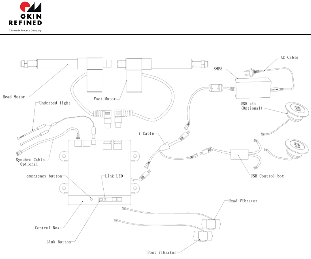
5、Connect to the Control Box

OKIN Refined Electric Technology Co.,Ltd
Page 5 of 5
The control box is designed for using the SMPS of 29VDC/ around 2A as the power. It is
necessary to use the SMPS provided by us when normal operation.
In the case of the AC power utility failure, the batteries for backup of 18VDC can be used as
the power. It is only for flatting the bed plate without load if the batteries used as the power
and each one of the batteries must be new with 9V voltage. You can press and hold the
emergency button on the body of the control box to flat the bed. The movement sequence
is that the Foot actuator goes down until arrives to the limit the Head one goes down. If
release the button, all movement will stop immediately including the massage motors.
It isn’t also strongly recommended to start the massage motors when the battery box used
as power.
FCC ID: PCU-JLDP03045
IC: 21319-JLDP03045
FCC Statement
Any Changes or modifications not expressly approved by the party responsible for compliance could void
the user’s authority to operate the equipment.
This device complies with part 15 of the FCC Rules. Operation is subject to the following two conditions:
(1) This device may not cause harmful interference, and
(2) This device must accept any interference received, including interference that may cause undesired
ISED RSS Warning:
This device complies with Innovation,Science and Economic Development Canada licenceexempt
RSS standard(s). Operation is subject to the following two conditions: (1) this device
may not cause interference, and (2) this device must accept any interference, including
interference that may cause undesired operation of the device.
Le présent appareil est conforme aux CNR d'ISED applicables aux appareils radio
exempts de licence.
L'exploitation est autorisée aux deux conditions suivantes:
(1) l'appareil ne doit pas produire de brouillage, et
(2) l'utilisateur de l'appareil doit accepter tout brouillage radioélectrique subi,
même si le brouillage est susceptible d'en compromettre le fonctionnement.