OLEVIA LCD Television Manual L0802251
LT23HVX L0802251
User Manual: OLEVIA OLEVIA LCD Television Manual OLEVIA LCD Television Owner's Manual, OLEVIA LCD Television installation guides
Open the PDF directly: View PDF ![]() .
.
Page Count: 41
OL_ |V| A
By_ SYNTAX
LCD Multi-Media Display
LT23HVX
zl u
(_Z) L P'- V I A
_SYNTAX
Syntax Groups Corporation _) 2005AII RightsReserved
www,syntaxgroups,com
For Customer Service Call 888-SYNTAX-8
MK0_UM00078G000
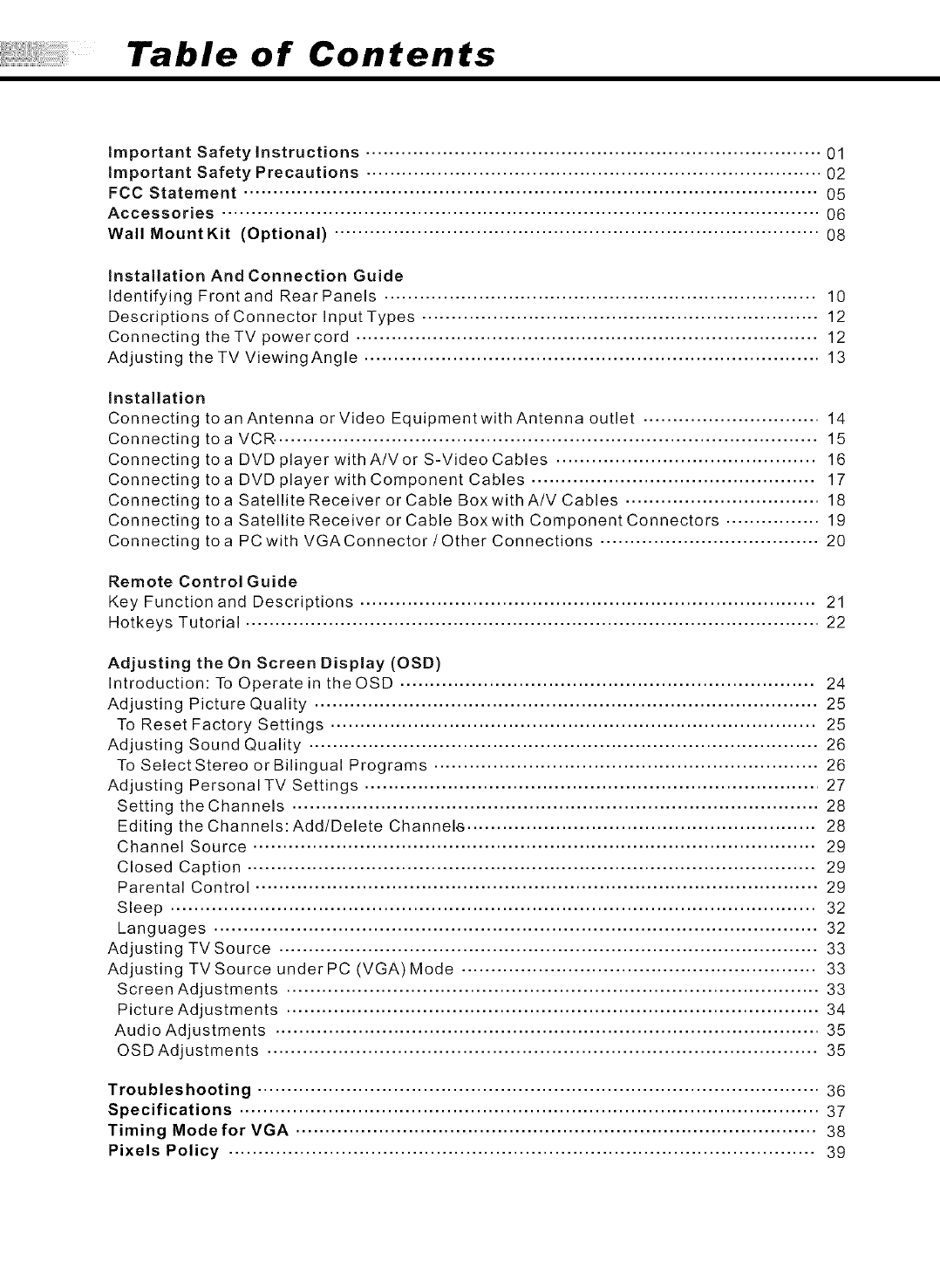
Table of Contents
important Safety instructions ............................................................................. 01
important Safety Precautions ............................................................................. 02
FCC Statement ................................................................................................. 05
Accessories ..................................................................................................... 06
WalIMountKit (Optional) .................................................................................. 08
Installation And Connection Guide
Identifying Frontand RearPanels ......................................................................... 10
Descriptions of Connector Input Types ................................................................... 12
Connecting theTV powercord .............................................................................. 12
Adjusting theTV ViewingAngle ............................................................................. 13
installation
Connecting to an Antenna or Video Equipmentwith Antenna outlet .............................. 14
Connecting
Connecting
Connecting
Connecting
Connecting
Connecting
to aVCR. ........................................................................................... 15
toa DVD player withA/Vor S-Video Cables ............................................ 16
toa DVD player with Component Cables ................................................ 17
toa Satellite Receiver or Cable Boxwith A/V Cables ................................. 18
toa Satellite Receiver or Cable Boxwith Component Connectors ................ 19
toa PC with VGAConnector/Other Connections ..................................... 20
Remote Control Guide
Key Function and Descriptions ............................................................................. 21
Hotkeys Tutorial ................................................................................................. 22
Adjusting the On Screen Display (OSD)
Introduction: To Operate in the OSD ...................................................................... 24
Adjusting Picture Quality ..................................................................................... 25
To Reset Factory Settings .................................................................................. 25
Adjusting Sound Quality ...................................................................................... 26
To Select Stereo or Bilingual Programs ................................................................. 26
Adjusting PersonalTV Settings ............................................................................. 27
Setting the Channels ......................................................................................... 28
Editing the Channels: Add/Delete Channele ........................................................... 28
Channel Source ............................................................................................... 29
Closed Caption ................................................................................................ 29
Parental Control ............................................................................................... 29
Sleep ............................................................................................................. 32
Languages ...................................................................................................... 32
Adjusting TV Source ........................................................................................... 33
Adjusting TVSource under PC (VGA) Mode ............................................................ 33
Screen Adjustments .......................................................................................... 33
Picture Adjustments .......................................................................................... 34
Audio Adjustments ............................................................................................ 35
OSD Adjustments ............................................................................................. 35
Troubleshooting ............................................................................................... 36
Specifications .................................................................................................. 37
Timing Mode for VGA ........................................................................................ 38
Pixels Policy ................................................................................................... 39
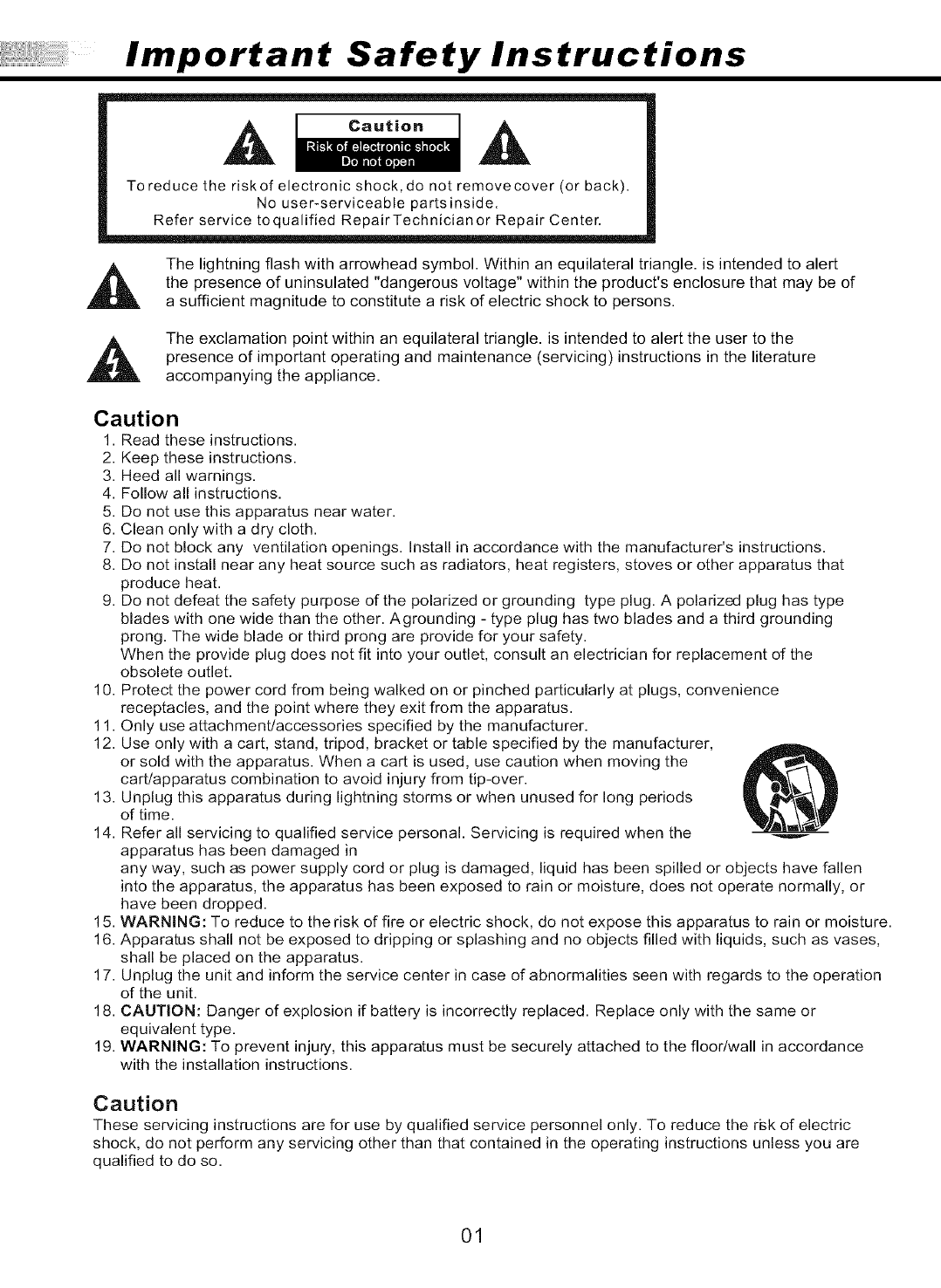
Important Safety Instructions
R
To reduce the risk of electronic shock, do not remove cover (or back).
No user-serviceable partsinside.
Refer service toqualified RepairTechnicianor Repair Center.
,_ The lightning flash with arrowhead symbol. Within an equilateral triangle, is intended to alert
the presence of uninsulated "dangerous voltage" within the product's enclosure that may be of
a sufficient magnitude to constitute a risk of electric shock to persons.
The exclamation point within an equilateral triangle, is intended to alert the user to the
presence of important operating and maintenance (servicing) instructions in the literature
accompanying the appliance.
Caution
1. Read these instructions.
2. Keep these instructions.
3. Heed all warnings.
4. Follow all instructions.
5. Do not use this apparatus near water.
6. Clean only with a dry cloth.
7. Do not block any ventilation openings. Install in accordance with the manufacturer's instructions.
8. Do not install near any heat source such as radiators, heat registers, stoves or other apparatus that
produce heat.
9. Do not defeat the safety purpose of the polarized or grounding type plug. A polarized plug has type
blades with one wide than the other. Agrounding - type plug has two blades and a third grounding
prong. The wide blade or third prong are provide for your safety.
When the provide plug does not fit into your outlet, consult an electrician for replacement of the
obsolete outlet.
10. Protect the power cord from being walked on or pinched particularly at plugs, convenience
receptacles, and the point where they exit from the apparatus.
11. Only use attachment/accessories specified by the manufacturer.
12. Use only with a cart, stand, tripod, bracket or table specified by the manufacturer,
or sold with the apparatus. When a cart is used, use caution when moving the
cart/apparatus combination to avoid injury from tip-over.
13. Unplug this apparatus during lightning storms or when unused for long periods
of time.
14. Refer all servicing to qualified service personal. Servicing is required when the
apparatus has been damaged in
any way, such as power supply cord or plug is damaged, liquid has been spilled or objects have fallen
into the apparatus, the apparatus has been exposed to rain or moisture, does not operate normally, or
have been dropped.
15. WARNING: To reduce to the risk of fire or electric shock, do not expose this apparatus to rain or moisture.
16. Apparatus shall not be exposed to dripping or splashing and no objects filled with liquids, such as vases,
shall be placed on the apparatus.
17. Unplug the unit and inform the service center in case of abnormalities seen with regards to the operation
of the unit.
18. CAUTION: Danger of explosion if battery is incorrectly replaced. Replace only with the same or
equivalent type.
19. WARNING: To prevent injury, this apparatus must be securely attached to the floorlwall in accordance
with the installation instructions.
Caution
These servicing instructions are for use by qualified service personnel only. To reduce the risk of electric
shock, do not perform any servicing other than that contained in the operating instructions unless you are
qualified to do so.
01
Important Safety Precautions
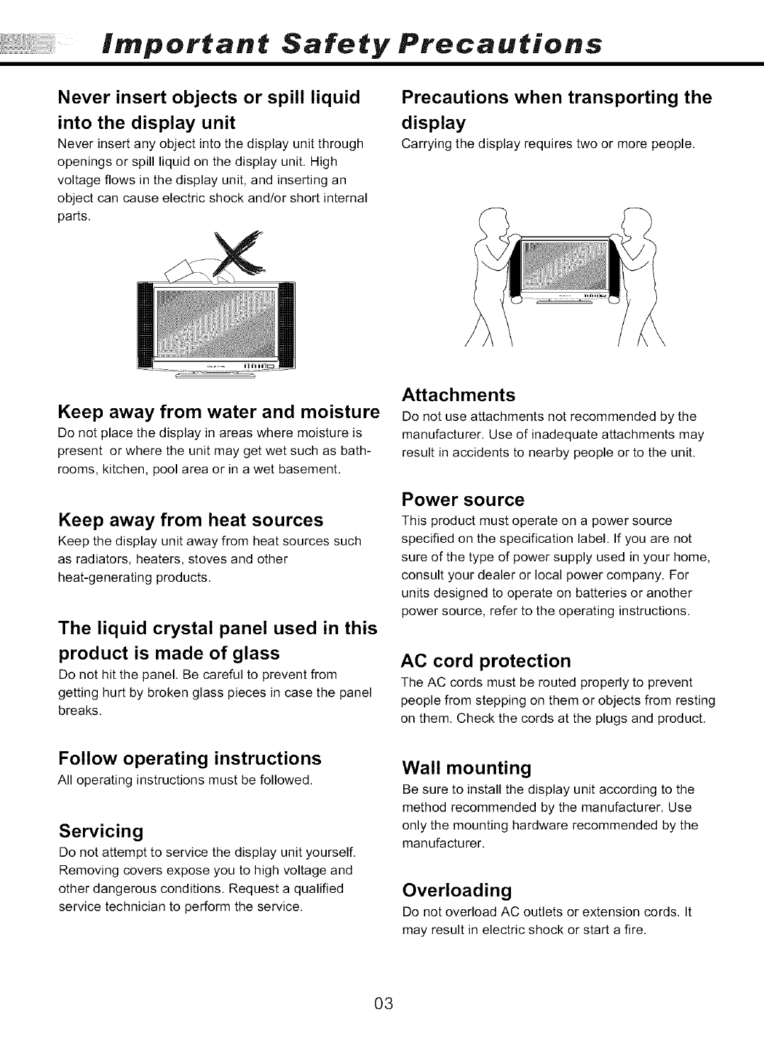
Never insert objects or spill liquid
into the display unit
Never insert any object into the display unit through
openings or spill liquid on the display unit. High
voltage flows in the display unit, and inserting an
object can cause electric shock and/or short internal
parts.
Precautions when transporting the
display
Carrying the display requires two or more people.
Keep away from water and moisture
Do not place the display in areas where moisture is
present or where the unit may get wet such as bath-
rooms, kitchen, pool area or in a wet basement.
Keep away from heat sources
Keep the display unit away from heat sources such
as radiators, heaters, stoves and other
heat-generating products.
The liquid crystal panel used in this
product is made of glass
Do not hit the panel. Be careful to prevent from
getting hurt by broken glass pieces in case the panel
breaks.
Follow operating instructions
All operating instructions must be followed.
Servicing
Do not attempt to service the display unit yourself.
Removing covers expose you to high voltage and
other dangerous conditions. Request a qualified
service technician to perform the service.
Attachments
Do not use attachments not recommended by the
manufacturer. Use of inadequate attachments may
result in accidents to nearby people or to the unit.
Power source
This product must operate on a power source
specified on the specification label. If you are not
sure of the type of power supply used in your home,
consult your dealer or local power company. For
units designed to operate on batteries or another
power source, refer to the operating instructions.
AC cord protection
The AC cords must be routed properly to prevent
people from stepping on them or objects from resting
on them. Check the cords at the plugs and product.
Wall mounting
Be sure to install the display unit according to the
method recommended by the manufacturer. Use
only the mounting hardware recommended by the
manufacturer.
Overloading
Do not overload AC outlets or extension cords. It
may result in electric shock or start a fire.
03
Important Safety Precautions
Replacement parts
In case the display unit needs replacement parts, make sure that the service technician uses
replacement parts specified by the manufacturer, or those with the same characteristics and
performance as the original parts. Use of unauthorized parts can result in fire, electric shock
and/or other danger.
Safety checks
Upon completion of service or maintenance, request the service technician to perform safety
checks toensure thatthe display unit isin proper operating condition.
Repair
When thedisplay unitdisplays an abnormal condition, any noticeableabnormality in the display
unit indicates that the display unit needs servicing.
If any of the following conditions occurs, unplug theAC cord from theAC outlet, and request a
qualified service person to perform repairs.
1.Aliquid wasspilled on the displayunit or objects havefallen intothe display unit.
2.The display unit has been exposed to rain or water.
3.The display unit has been dropped or damaged.
Environment
The display unit only operates within the temperature 0°C to 40°C.Operation outside of the
recommended may cause damage to your product.
04
FCC Statement
Caution
This product satisfies FCC regulations when shielded cables and connectors are used to
connect the unit to other equipment.
Prevent electromagnetic interference from electrical appliances such as radios and televisions.
Please use shielded cables and connectors for connections.
Warning
FCC Regulations state that any unauthorized changes or modifications to this equipment
not expressly approved by the manufacturer could void the user's authority to operate this
equipment.
FCC notice
This equipment has been tested and found to comply with the limits for a Class Bdigital device,
pursuant to part 15of the FCC Rules. These limits are designed to provide reasonable protection
against harmful interference in a residential installation. This equipment generates, uses and can
radiate radio frequency energy and, if not installed and used in accordance with the instructions,
may cause harmful interference to radio communications. However, there is no guarantee that
interference will not occur in aparticular installation. If this equipment does cause harmful
interference to radio or television reception, which can be determined by turning the equipment off
and on, the user is encouraged to try to correct the interference by one or more of the following
measures:
1.Reorient or relocate the receiving antenna.
2.Increase the separation between the equipment and receiver.
3.Connectthe equipment into an outlet ona circuit different from that to which the receiver is
connected.
4.Consult the dealer or an experienced radio/TV technician for help.
Modifications not expressly approved by the manufacturer could void the user's authority to
operated the equipment under FCC rules. This device complies with part 15of the FCC Rules.
Operation is subject to the following two conditions:
1.This device may not cause harmful interference.
2.This device must accept any interference received, including interference that maycause
undesired operation.
For Canadian model
This Class B digital apparatus complieswith Canadian ICES-003.
Approval
0® ,s.o
I.T.E. LT23HVX ®
US E247591
Also Listed co,,,lie,wi_,co,,clio,tcEs-o03c,o,0
as AV Product 225962
05
Accessories
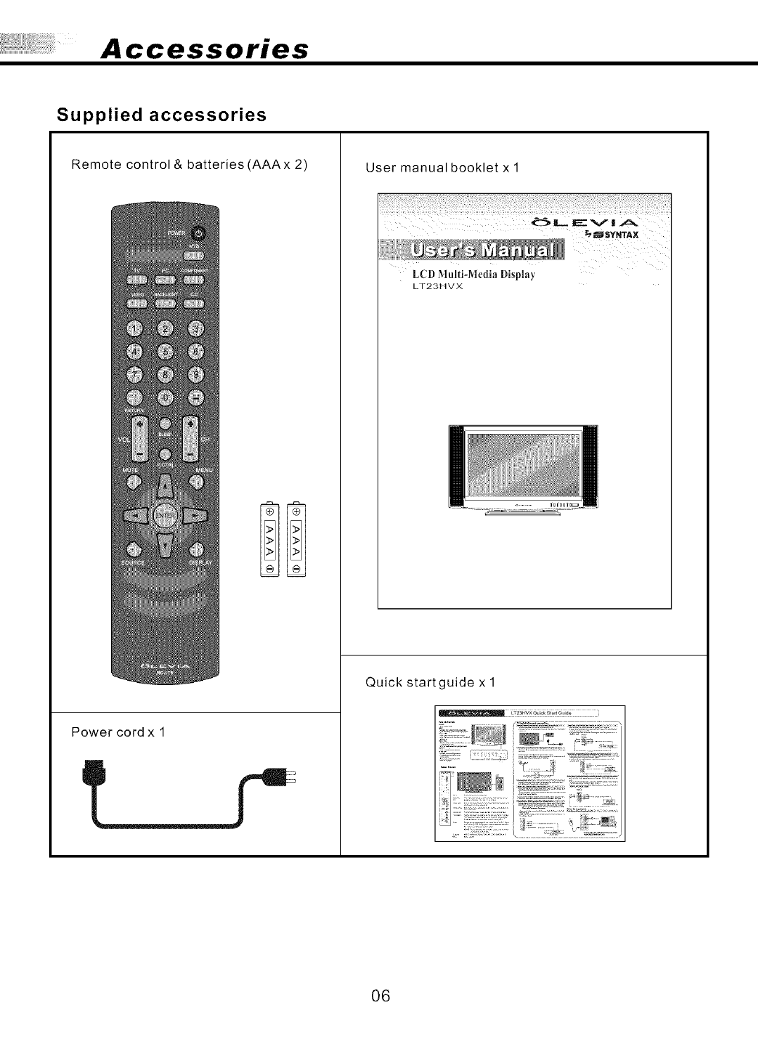
Supplied accessories
Remote control & batteries (AAAx 2)
Power cord x 1
User manual booklet x
!iiii!!!i;_i!ii_!!i_iiiii!i_i_i!ii,li_:!i¸I!¸I¸!_!!ii_iii_i!il_ii!_:!iiil;ii¸iil;ii!i:_i¸_I!¸i!i!i!!!iiiiiii!i¸I¸iii!!!ii_i!!!i!ii!i¸i!!!!!i:ii!i!_i_i¸i_i!!ii¸ii_!i_!!;_i_i_i!i!:iiii_ii_i!!ili!i_!!_i_i_i_IJi_ii!_i_i!_'i_i!!'_i¸_i_i!¸_ili_i¸!!I!¸!i!_ii_i_i¸i_i_i!i¸I:¸II!!II¸¸I¸¸!I!¸I¸¸iii!i!!iiiii!_iiii_i_i!i¸ii¸iiii!:!i_i¸!i!!_ii¸i_!_i!i!¸!i!i¸ii:_i_i_ii!i!_!ii!i¸i_ii_i_i!_!!_i;!;iii_!!_iiiii!:_!i:ii!_i¸ii¸i_i
_$YNTAX
LCD Multi-Media l)isp|ay
LT23HVX
Quick start guide x 1
06
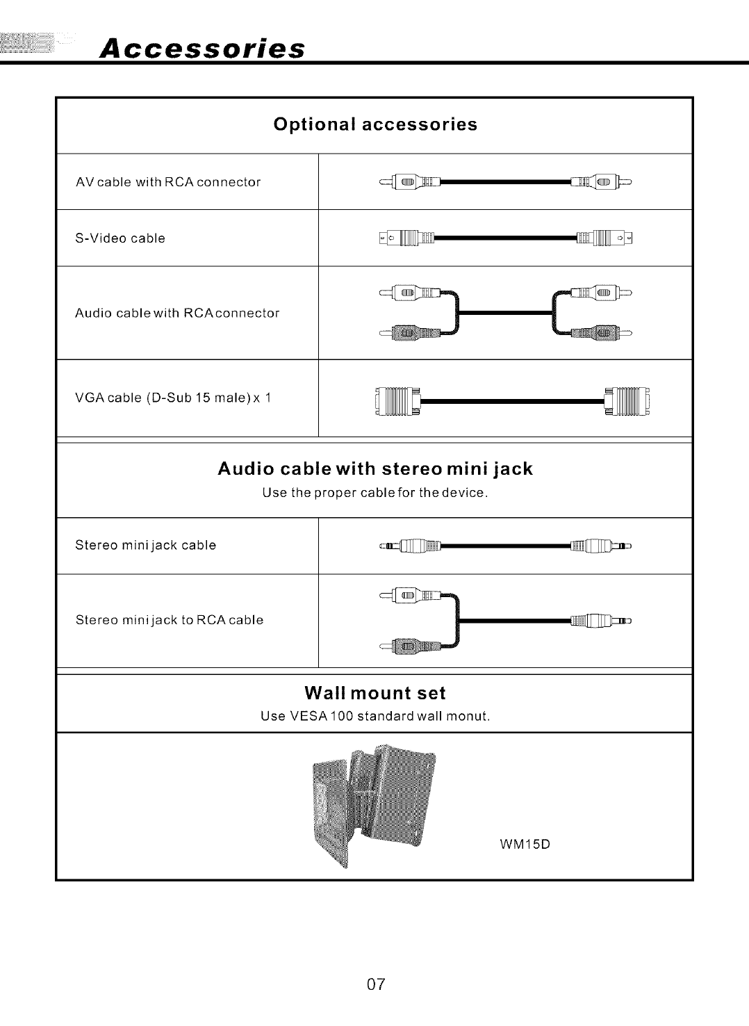
Accessories
Optional accessories
AV cable with RCA connector
S-Video cable
Audio cablewith RCAconnector
VGAcable (D-Sub 15 male)x 1
Audio cablewith stereo mini jack
Use the proper cable for the device.
Stereo mini jack cable
Stereo mini jack to RCA cable
Wall mount set
Use VESA 100 standard wall monut.
WM15D
07
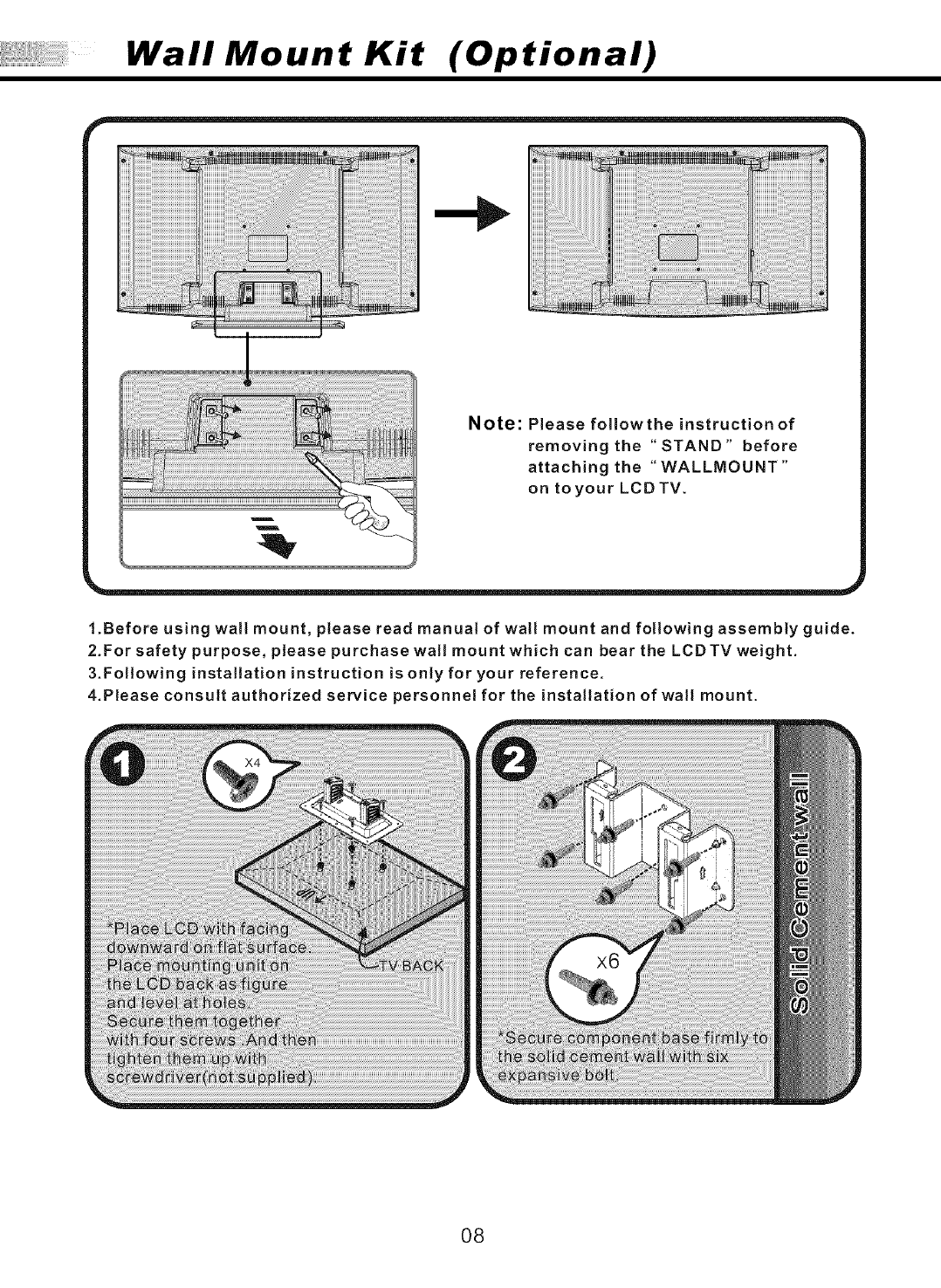
Wall Mount Kit (Optional)
iiiiiiiiiiiiiiiiiiiiiiii
Note: Please followthe instruction of
removing the "STAND" before
attaching the "WALLMOUNT"
on toyour LCD TV.
1.Before using wall mount, please read manual of wall mount and following assembly guide.
2.For safety purpose, please purchase wall mount which can bear the LCDTV weight.
3.Following installation instruction is only for your reference.
4.Please consult authorized service personnel for the installation of wall mount.
O8
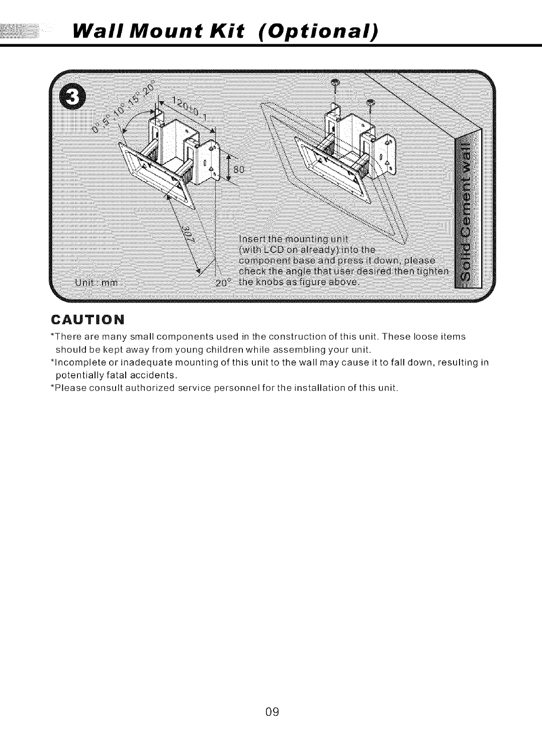
Wall Mount Kit (Optional)
CAUTION
*There are many small components used in the construction of this unit. These loose items
should be kept away from young children while assembling your unit.
*Incomplete or inadequate mounting of this unit to the wall may cause it to fall down, resulting in
potentially fatal accidents.
*Please consult authorized service personnel for the installation of this unit.
O9
TV Installation and Connection Guide
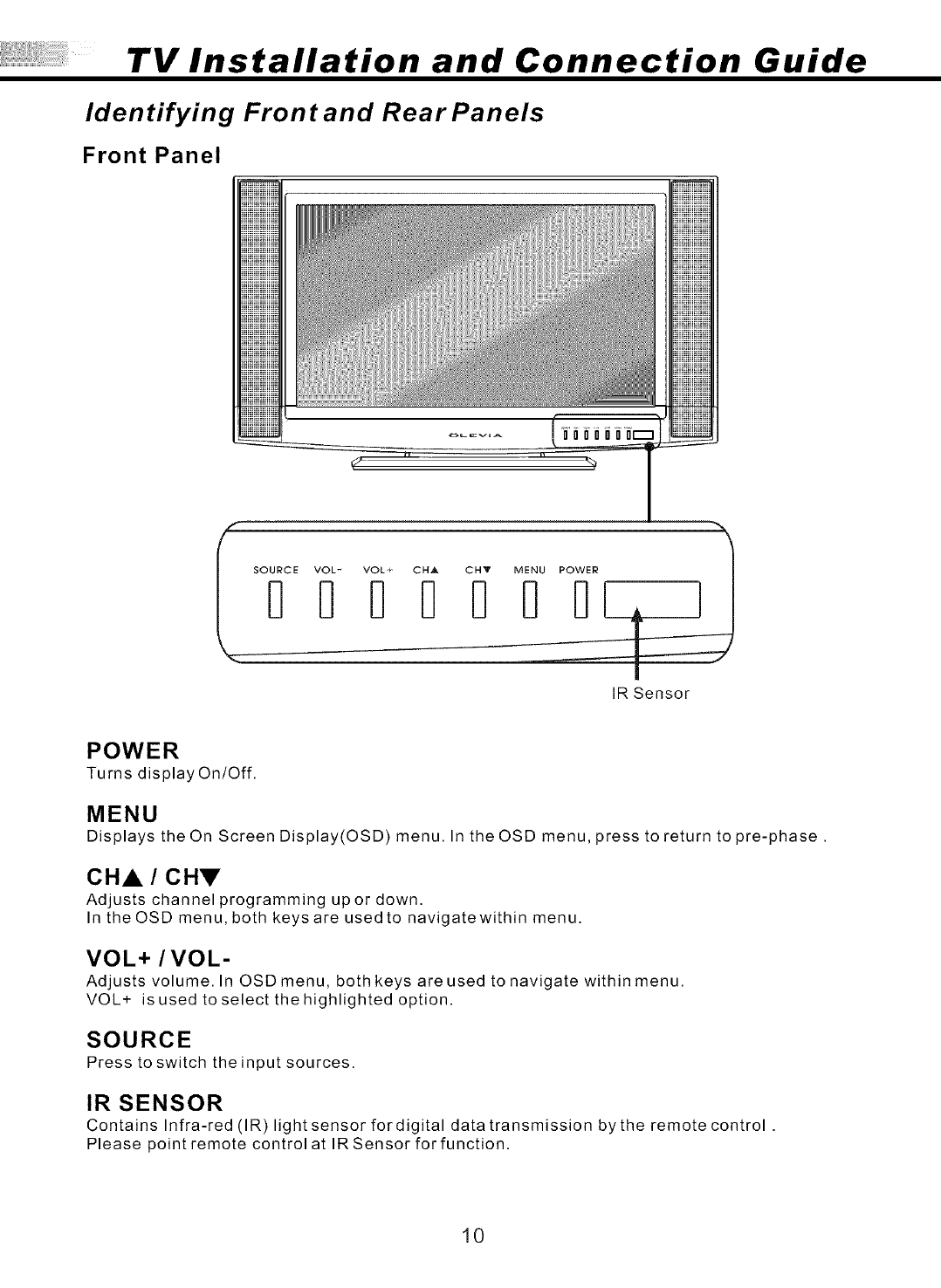
Identifying Front and Rear Panels
Front Panel
SOURCE VOL- VOL+ CH_ CHY MENU POWER
I
IR Sensor
POWER
Turns display On/Off.
MENU
Displays the On Screen Display(OSD) menu. In the OSD menu, press to return to pre-phase.
CHA /CHV
Adjusts channel programming upor down.
In the OSD menu, both keys are used to navigatewithin menu.
VOL+ /VOL-
Adjusts volume. In OSD menu, both keys are used to navigate within menu.
VOL+ is used to select the highlighted option.
SOURCE
Press to switch the input sources.
IR SENSOR
Contains Infra-red (IR)light sensor for digital data transmission by the remote control .
Please point remote control at IRSensor forfunction.
10
TV Installation and Connection Guide
Identifying Front and Rear Panels
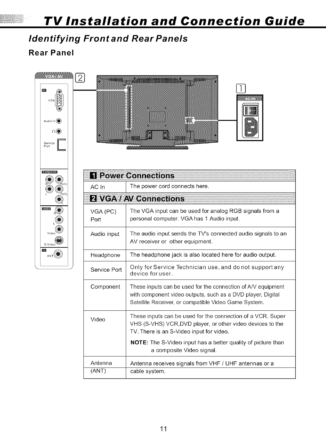
Rear Panel
I_ VGA_
Audio In (_)
Service E
Port
®
L®
Video ®
S Video @
Ig_! ANT_
03
AC In The power cord connects here.
VGA (PC) The VGA input can be used for analog RGB signals from a
Port personal computer. VGA has 1 Audio input.
Audio input The audio input sends the TV's connected audio signals to an
AV receiver or other equipment.
Headphone The headphone jack is also located here for audio output.
Service Port Only for Service Technician use, and do not supportany
device for user.
Component These inputs can be used for the connection of A/V equipment
with component video outputs, such as a DVD player, Digital
Satellite Receiver, or compatible Video Game System.
Video These inputs can be used for the connection of a VCR, Super
VHS (S-VHS) VCR,DVD player, or other video devices to the
TV. There is an S-Video input for video.
NOTE: The S-Video input has a better quality of picture than
a composite Video signal.
Antenna Antenna receives signals from VHF /UHF antennas or a
(ANT) cable system.
11
TV Installation and Connection Guide
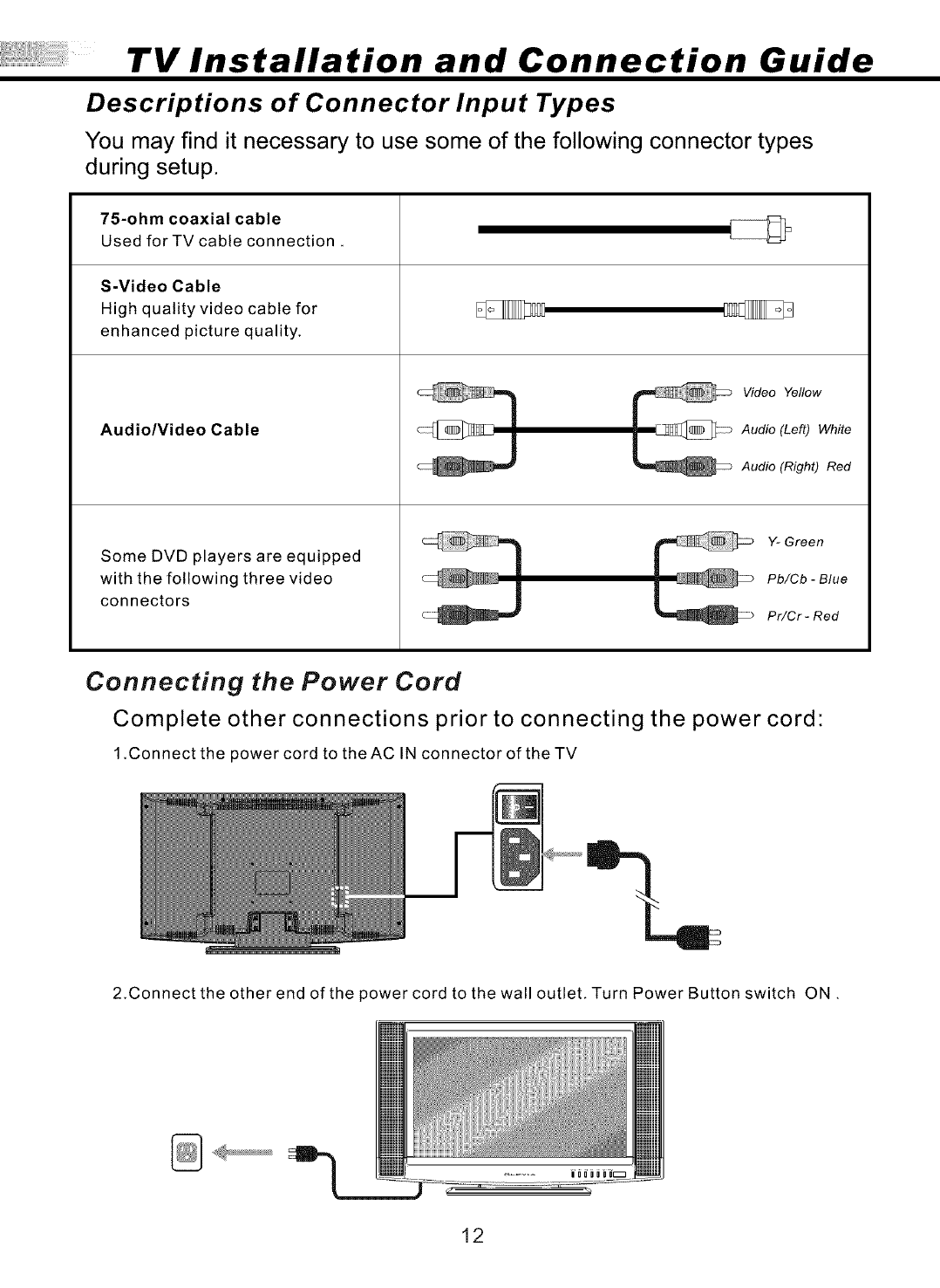
Descriptions of Connector Input Types
You may find it necessary to use some of the following connector types
during setup.
75-ohm coaxial cable
Used forTV cable connection.
S-Video Cable
High quality video cable for
enhanced picture quality.
Audio/Video Cable
Some DVD players are equipped
with the following three video
connectors
Video Yellow
Audio (Left) White
Audio (Right) Red
Y- Green
Pb/Cb -Blue
Pr/Cr -Red
Connecting the Power Cord
Complete other connections prior to connecting the power cord:
1.Connectthe power cord to theAC IN connector of theTV
2.Connect the other end of the power cord to the wall outlet. Turn Power Button switch ON.
•
12
TV Installation and Connection Guide
Installation
In the following pages, you will find directions on how to install your TV with
your choice of video equipment.
• Connecting to an Antenna or Video Equipment with Antenna outlet
• Connecting to a VCR
• Connecting to a DVD Player with A/V or S-Video Cables
• Connecting to a DVD Player with Component Cables
• Connecting to a Satellite Receiver or Cable Box with A/V Cables
• Connecting to a Satellite Receiver or Cable Box With Component Connectors
• Connecting to a PC with VGA Connector
• Other Connections
13
TV Installation and Connection Guide
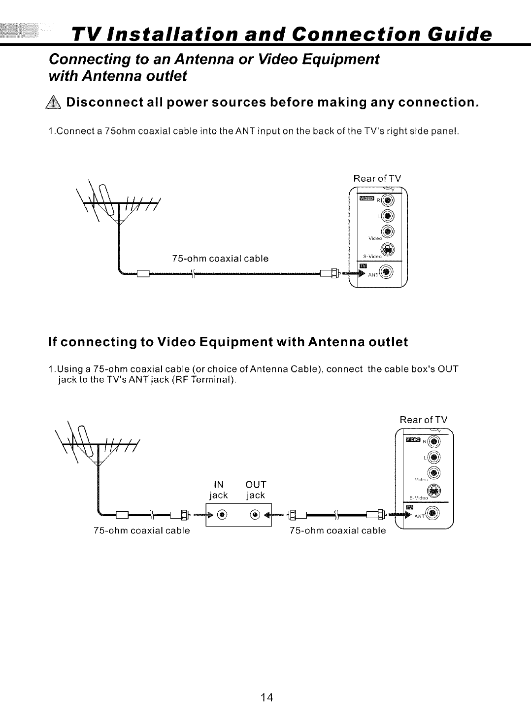
Connecting to an Antenna or Video Equipment
with Antenna outlet
Disconnect all power sources before making any connection.
1.Connect a 75ohm coaxial cable into the ANT input on the back of theTV's right side panel,
\//(/
/
75-ohm coaxial cable
Rear of TV
_ V_d e°_)
If connecting to Video Equipment with Antenna outlet
1.Using a 75-ohm coaxial cable (or choice of Antenna Cable), connect the cable box's OUT
jack to the TV's ANT jack (RF Terminal).
Itl //
1/_ II
/
IN
jack
75-ohm coaxial cable
Rear of TV
L®
V_deo ®
OUT
jack
75-ohm coaxial cable
14
TV Installation and Connection Guide
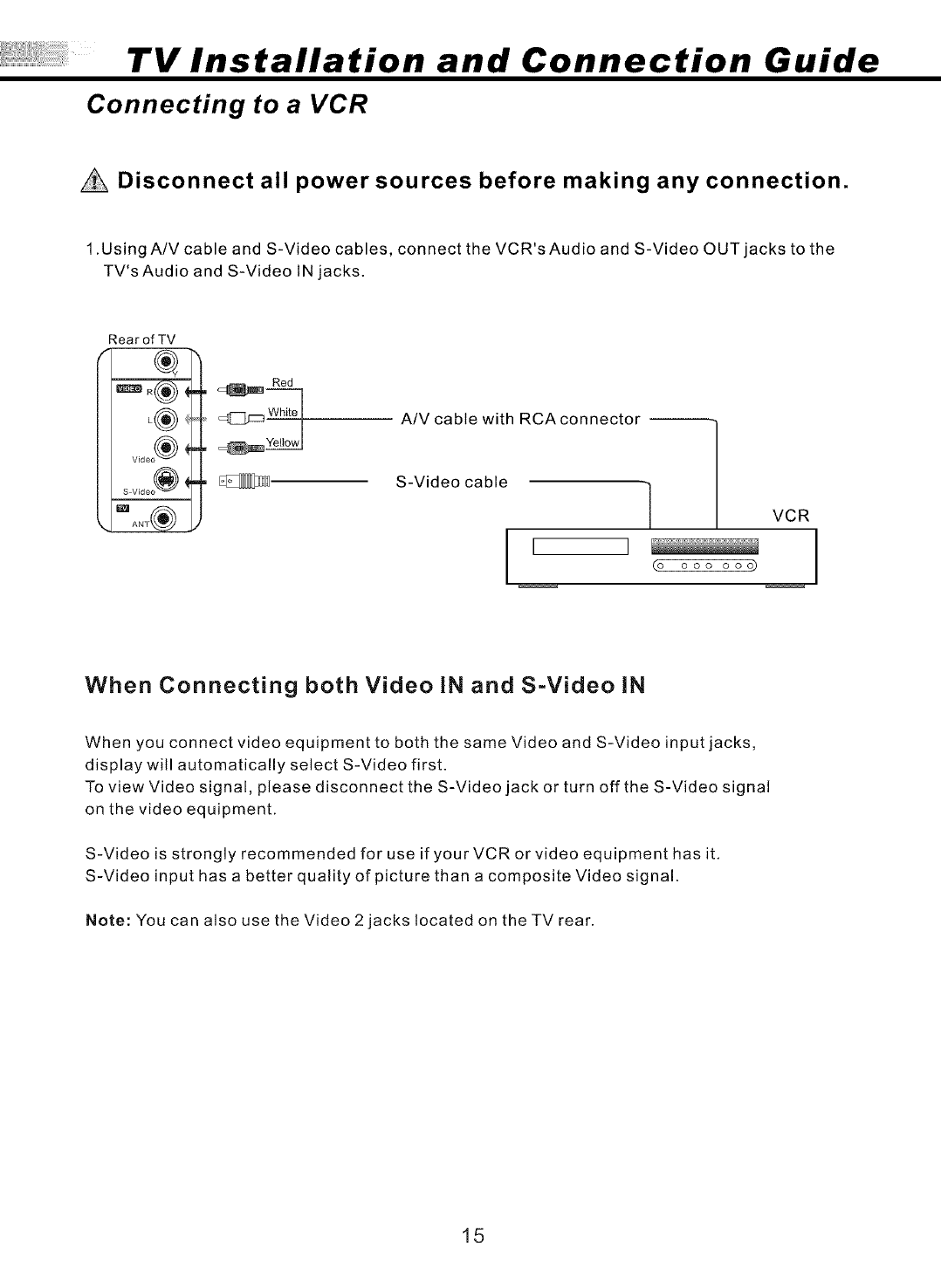
Connecting to a VCR
Disconnect all power sources before making any connection.
1.Using A/V cable and S-Video cables, connect the VCR's Audio and S-Video OUT jacks to the
TV's Audio and S-Video tN jacks.
Rear of TV
Red
A/V cable with RCAconnector --
S-Video cable
VCR
(o ooo ooo)
When Connecting both Video IN and S-Video iN
When you connect video equipment to both the same Video and S-Video input jacks,
display will automatically select S-Video first.
To view Video signal, please disconnect the S-Video jack or turn off the S-Video signal
on the video equipment.
S-Video is strongly recommended for use if your VCR or video equipment has it,
S-Video input has a better quality of picture than a composite Video signal.
Note: You can also use the Video 2jacks located on theTV rear.
15
TV Installation and Connection Guide
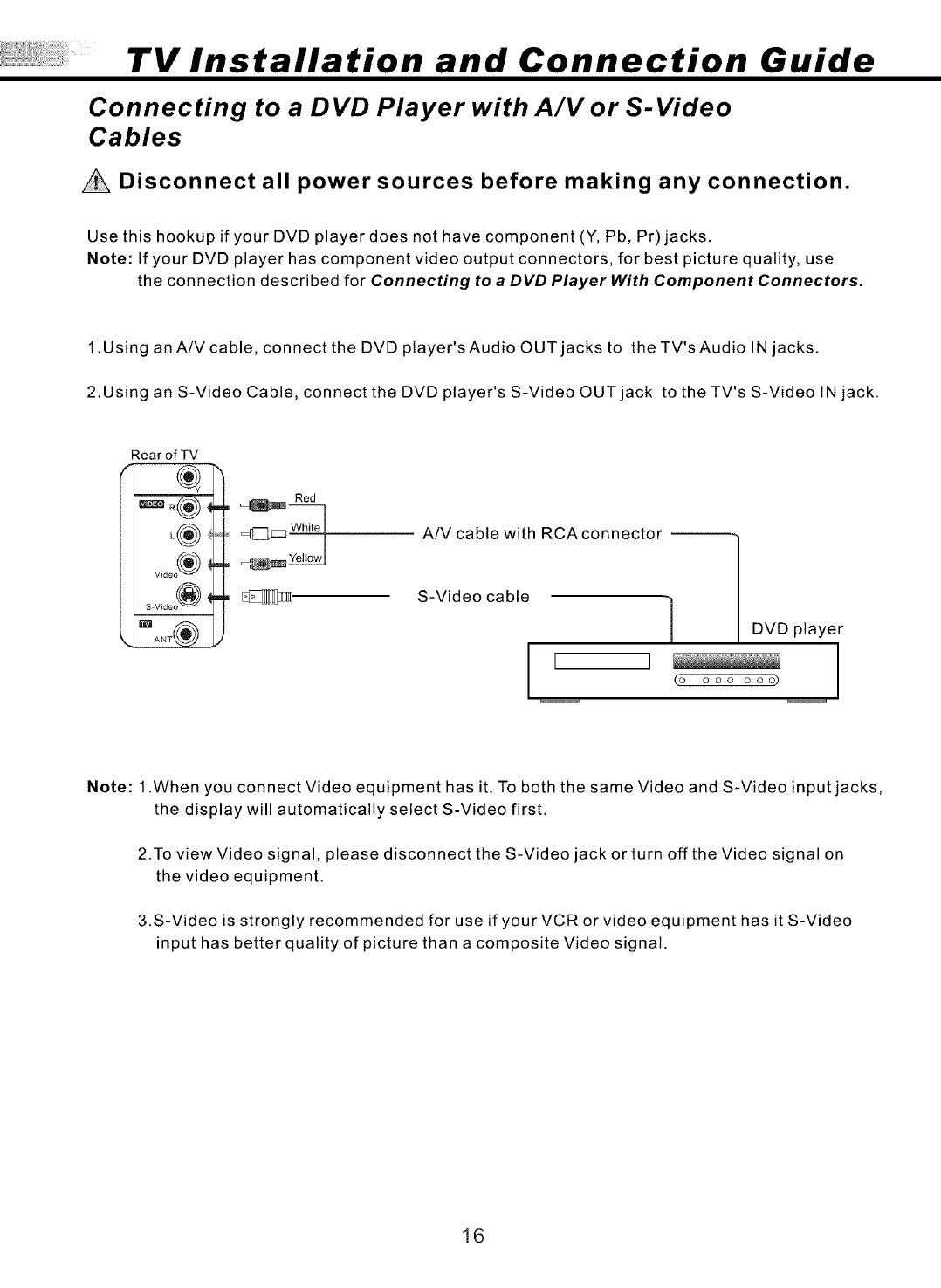
Connecting to a DVD Player with A/V or S-Video
Cables
Disconnect all power sources before making any connection.
Use this hookup if your DVD player does not have component (Y, Pb, Pr) jacks.
Note: If your DVD player has component video output connectors, for best picture quality, use
the connection described for Connecting to a DVD Player With Component Connectors.
1.Using an A/V cable, connect the DVD player's Audio OUT jacks to the TV's Audio IN jacks.
2.Using an S-Video Cable, connect the DVD player's S-Video OUT jack to the TV's S-Video IN jack.
RearofTV
L®
V_deo ®
S V_deo (_
Red
A/V cable with RCAconnector --
S-Video cable 1
I ]
(o
DVD player
ooo ooo) I
Note: 1 .When you connect Video equipment has iL To both the same Video and S-Video input jacks,
the display will automatically select S-Video first.
2.To view Video signal, please disconnect the S-Video jack or turn off the Video signal on
the video equipment.
3.S-Video is strongly recommended for use if your VCR or video equipment has it S-Video
input has better quality of picture than a composite Video signal.
16
TV Installation and Connection Guide
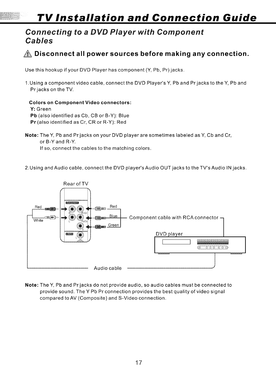
Connecting to a DVD Player with Component
Cables
Disconnect all power sources before making any connection.
Use this hookup if your DVD Player has component (Y, Pb, Pr)jacks.
1.Using a component video cable, connect the DVD Player'sY, Pb and Prjacks to the Y, Pb and
Pr jacks on the TV.
Colors on Component Video connectors:
Y: Green
Pb (also identified as Cb, CB or B-Y): Blue
Pr (also identified as Cr, CRor R-Y): Red
Note: TheY, Pb and Prjacks on your DVD player are sometimes labeled as Y, Cb and Cr,
or B-Y and R-Y.
If so, connect the cables to the matching colors.
2.Using and Audio cable, connect the DVD player's Audio OUT jacks to the TV's Audio IN jacks.
Rear of TV
Red
White ®4
,,_:_ Red
,_ Component cable with RCA connector
,_ ereenl 1
DVD player
l [ I co oooooo _
Audio cable J
I
Note: TheY, Pb and Prjacks do not provide audio, so audio cables must be connected to
provide sound. The Y Pb Pr connection provides the best quality of video signal
compared toAV (Composite) and S-Video connection.
17
TV Installation and Connection Guide
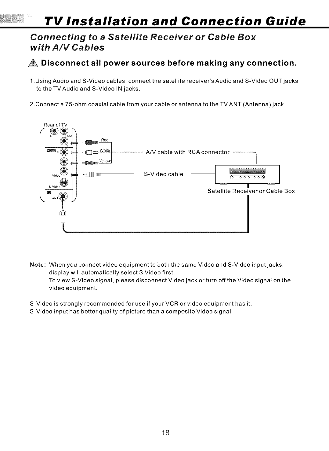
Connecting to a Satellite Receiver or Cable Box
with A/V Cables
Disconnect all power sources before making any connection.
1.Using Audio and S-Video cables, connect the satellite receiver's Audio and S-Video OUT jacks
to the TVAudio and S-Video IN jacks.
2.Connect a 75-ohm coaxial cable from your cable or antenna to the TV ANT (Antenna) jack.
Rear of TV
Red
A/V cable with RCAconnector ]
/
S-Video cable t (o ooo ooo)
Satellite Receiver or Cable Box
Note: When you connect video equipment to both the same Video and S-Video input jacks,
display will automatically select S Video first.
To view S-Video signal, please disconnect Video jack or turn off the Video signal on the
video equipment.
S-Video is strongly recommended for use if your VCR or video equipment has it.
S-Video input has better quality of picture than a composite Video signal.
18
TV Installation and Connection Guide
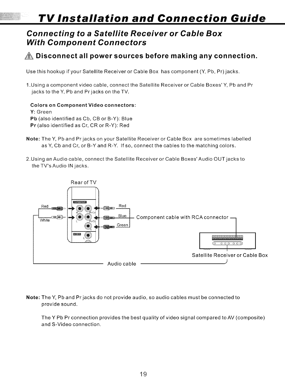
Connecting to a Satellite Receiver or Cable Box
With Component Connectors
Disconnect all power sources before making any connection.
Use this hookup if your Satellite Receiver or Cable Box has component (Y, Pb, Pr) jacks.
t.Using a component video cable, connect the Satellite Receiver or Cable Boxes' Y, Pb and Pr
jacks to theY, Pb and Prjacks on theTV.
Colors on Component Video connectors:
Y: Green
Pb (also identified as Cb, CB or B-Y): Blue
Pr (also identified as Cr, CR or R-Y): Red
Note: TheY, Pb and Prjacks on your Satellite Receiver or Cable Box are sometimes labelled
as Y, Cb and Cr, or B-Yand R-Y. If so, connect the cables to the matching colors.
2.Using an Audio cable, connect the Satellite Receiver or Cable Boxes' Audio OUT jacks to
the TV's Audio IN jacks.
Rear of TV
Red Red
Component cable with RCAco_
(o ooo ooo)
Satellite Receiver or Cable Box
Audio cable )
Note: The Y, Pb and Pr jacks do not provide audio, so audio cables must be connected to
provide sound.
The Y Pb Pr connection provides the best quality of video signal compared to AV (composite)
and S-Video connection.
19
TV Installation and Connection Guide
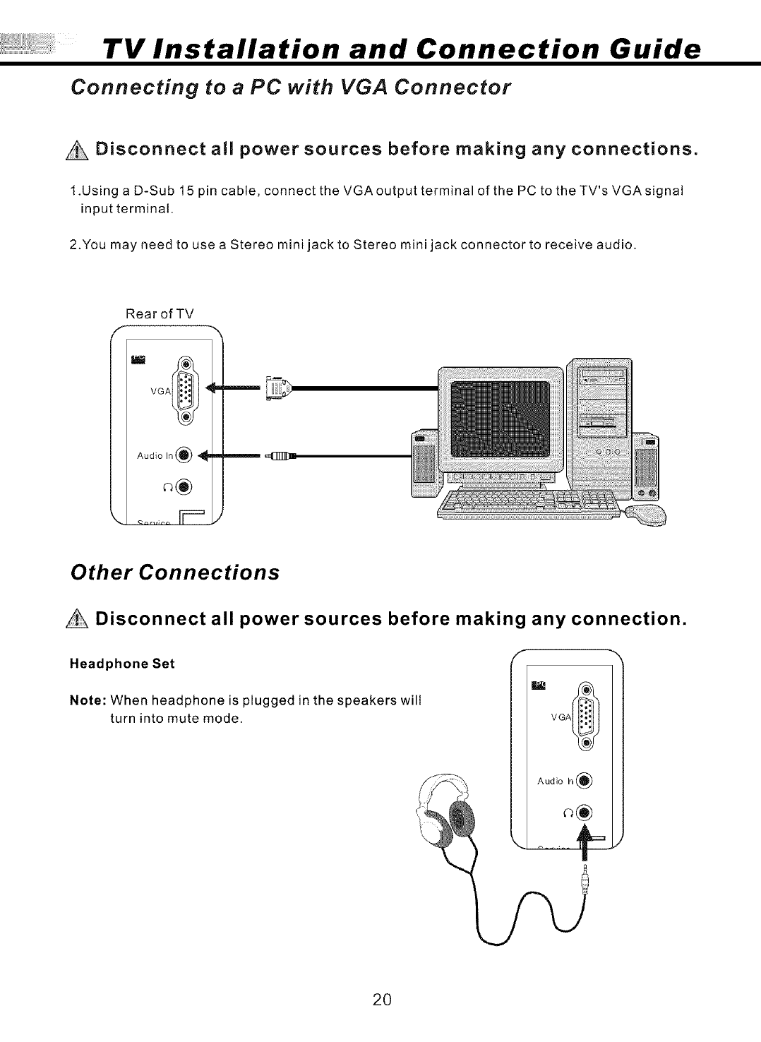
Connecting to aPC with VGA Connector
Disconnect all power sources before making any connections.
1.Using a D-Sub 15 pin cable, connect the VGAoutput terminal of the PC to theTV's VGAsignal
input terminal.
2.You may need to use a Stereo mini jack to Stereo mini jack connector to receive audio.
Rear of TV
VGA_ _
Audio In _ _I_
Other Connections
Disconnect all power sources before making any connection.
Headphone Set
Note: When headphone is plugged in the speakers will
turn into mute mode.
VGA_
!_! Audio In(_
20
Remote Control Guide
Remote Function Keys & Description
Regular Buttons
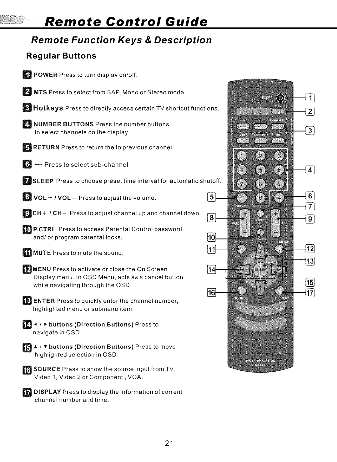
_POWER Press to turn display on/off.
DMTS Press to select from SAP, Mono or Stereo mode.
DHotkeys Press to directly access certain TV shortcut functions.
D NUMBER BUTTONS Press the number buttons
to select channels on the display.
D RETURN Press to return the to previous channel.
D m Press to select sub-channel
DSLEEP Press to choose preset time interval for automatic shutoff.
D VOL + !VOL- Press to adjust the volume.
DCH+ /CH- Press to adjust channel up and channel down.
_P.OTRL Press to access Parental Control password
and/or program parental locks.
_MUTE Press to mute the sound.
_MENU Press to activate or close the On Screen
Display menu. In OSD Menu, acts as a cancel button
while navigating through the OSD.
_ ENTER Press to quickly enter the channel number,
highlighted menu or submenu item.
_/_ buttons (Direction Buttons) Press to
navigate in OSD
_A /T buttons (Direction Buttons) Press to move
highlighted selection in OSD
_SOURCE Press to show the source input from TV,
Video 1, Video 2 or Component, VGA.
_ DISPLAY Press to display the information of current
channel number and time.
21

Remote Control Guide
Remote Function Keys & Description
Hot Keys Tutorial
The remote control contains 8 additional Hotkeys. Hot keys enable you to directly change the
setting to your preference without having to navigate through the OSD (On Screen Display) Menu.
How to use your Het Keys
HOTKEYFUNCTION
TV
Press to switch between TV and DTV Mode
(optional function currently unavailable)
TV PC COMPONENT
VIDEO BACKLIGHT C.C
PC
Press to switch to VGA Mode.
COMPONENT
Press to switch to Component source.
VIDEO
Press to switch between Video 1 and Video 2 sources.
BACKLIGHT
Press to view the screen at different levels of lighting at:
Bright, Normal and Soft
C,C,
Press to call up the Close Caption (CC) and Caption
Service (CS) list. You can pre-select one to see Closed Caption.
22
Remote Control Guide
Remote Function Keys & Description
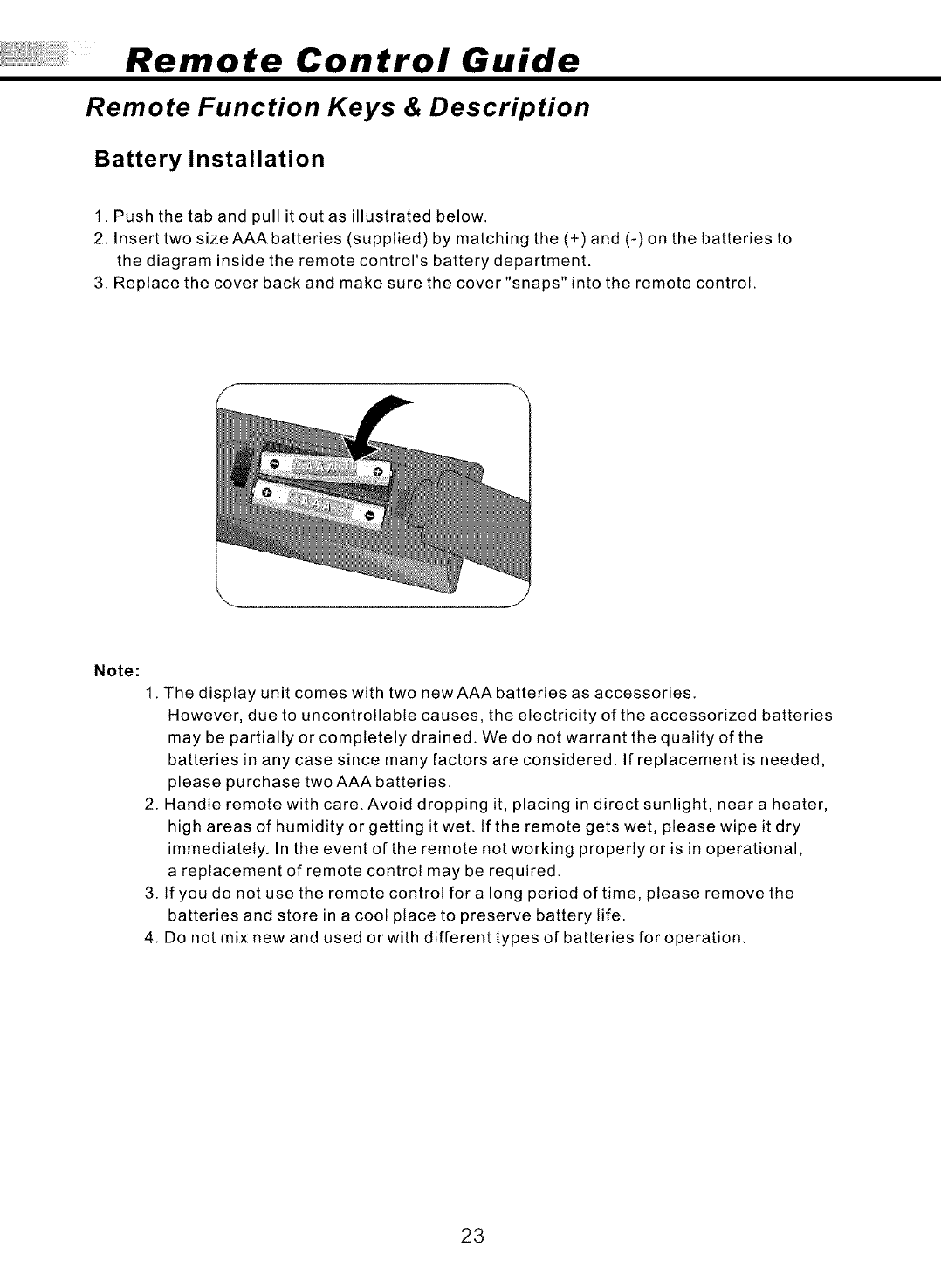
Battery Installation
1. Push the tab and pull it out as illustrated below.
2. Insert two size AAA batteries (supplied) by matching the (+) and (-) on the batteries to
the diagram inside the remote control's battery department.
3. Replace the cover back and make sure the cover "snaps" into the remote control.
Note:
1. The display unit comes with two new AAA batteries as accessories.
However, due to uncontrollable causes, the electricity of the accessorized batteries
may be partially or completely drained. We do not warrant the quality of the
batteries in any case since many factors are considered. If replacement is needed,
please purchase two AAA batteries.
2. Handle remote with care. Avoid dropping it, placing in direct sunlight, near a heater,
high areas of humidity or getting it weL tf the remote gets wet, please wipe it dry
immediately. In the event of the remote not working properly or is in operational,
a replacement of remote control may be required.
3. If you do not use the remote control for a long period of time, please remove the
batteries and store in a cool place to preserve battery life.
4. Do not mix new and used or with different types of batteries for operation.
23
Adjusting On Screen Displays (OSD)
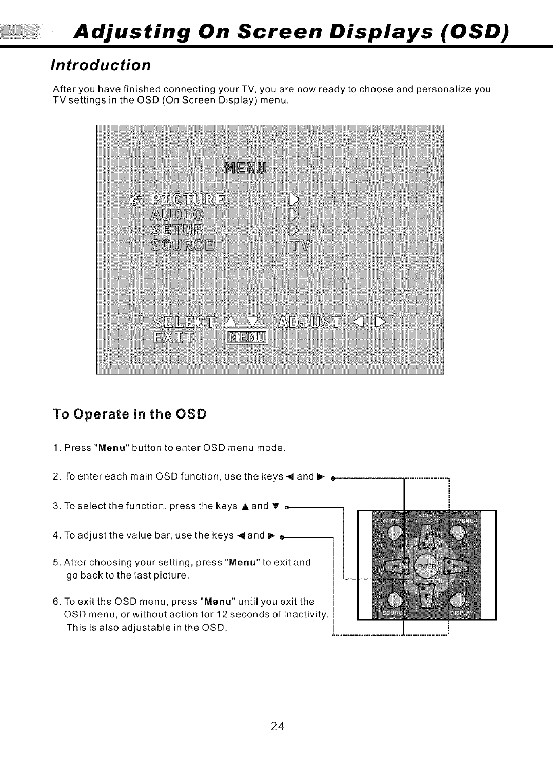
Introduction
After you have finished connecting your TV, you are now ready to choose and personalize you
TV settings in the OSD (On Screen Display) menu.
To Operate in the OSD
1. Press "Menu" button to enter OSD menu mode.
2. To enter each main OSD function, use the keys < and _ =
3. To select the function, press the keys A and T •
4. To adjust the value bar, use the keys _ and _
5. After choosing your setting, press "Menu" to exit and
go back to the last picture.
6. To exit the OSD menu, press "Menu" until you exit the
OSD menu, or without action for 12 seconds of inactivity.
This is also adjustable in the OSD.
24
Adjusting On Screen Displays (OSD)
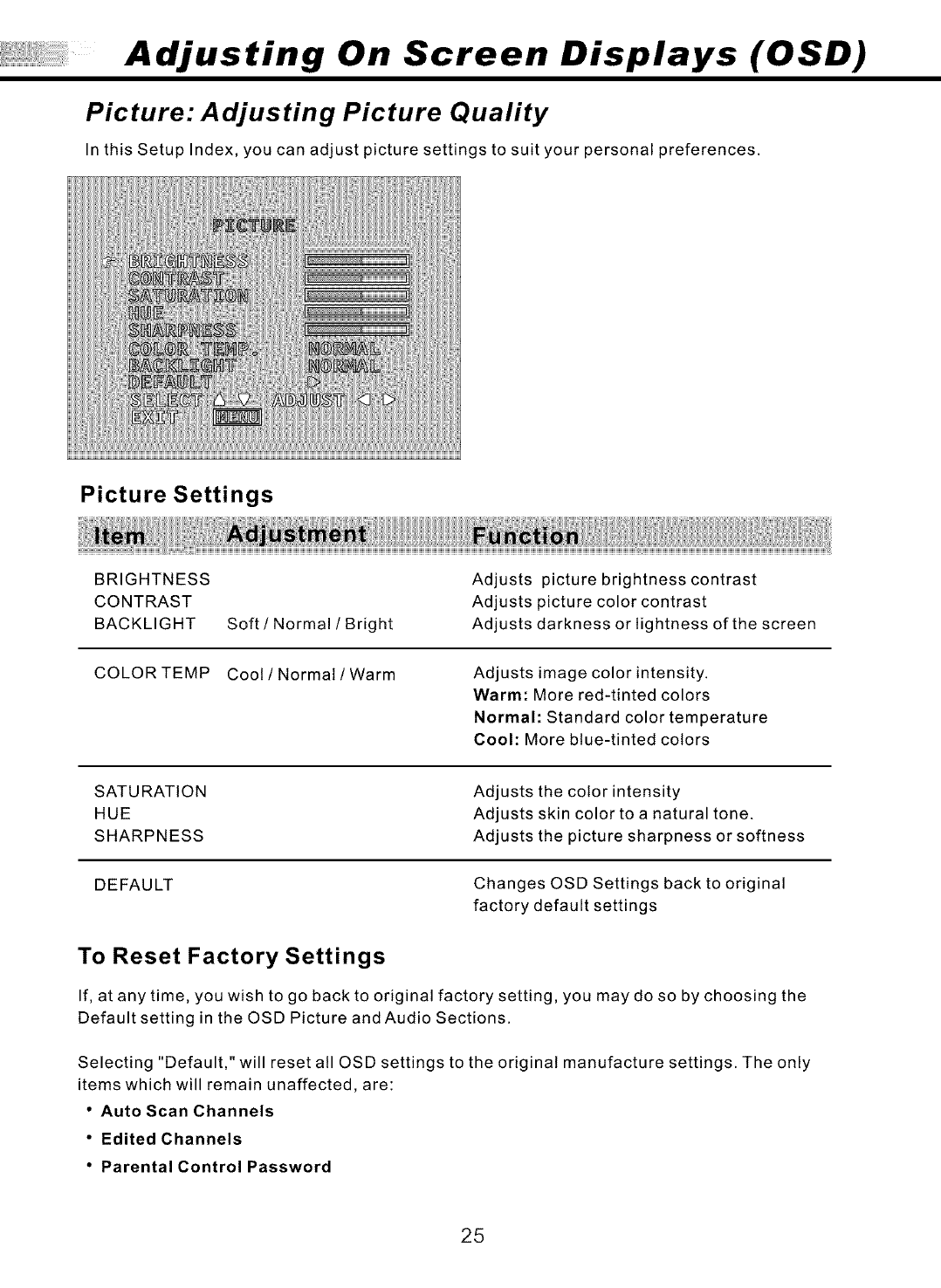
Picture: Adjusting Picture Quality
In this Setup Index, you can adjust picture settings to suit your personal preferences.
Picture Settings
BRIGHTNESS
CONTRAST
BACKLIGHT
COLORTEMP
Soft /Normal /Bright
Adjusts picture brightness contrast
Adjusts picture color contrast
Adjusts darkness or lightness of the screen
Coot /Normal /Warm Adjusts image color intensity.
Warm: More red-tinted colors
Normal: Standard color temperature
Cool: More blue-tinted colors
SATURATION
HUE
SHARPNESS
Adjusts the color intensity
Adjusts skin color to a natural tone.
Adjusts the picture sharpness or softness
DEFAULT Changes OSD Settings back to original
factory default settings
To Reset Factory Settings
If, at any time, you wish to go back to original factory setting, you may do so by choosing the
Default setting in the OSD Picture and Audio Sections.
Selecting "Default," will reset all OSD settings to the original manufacture settings. The only
items which will remain unaffected, are:
• Auto Scan Channels
•Edited Channels
•Parental Control Password
25
Adjusting On Screen Displays (OSD)
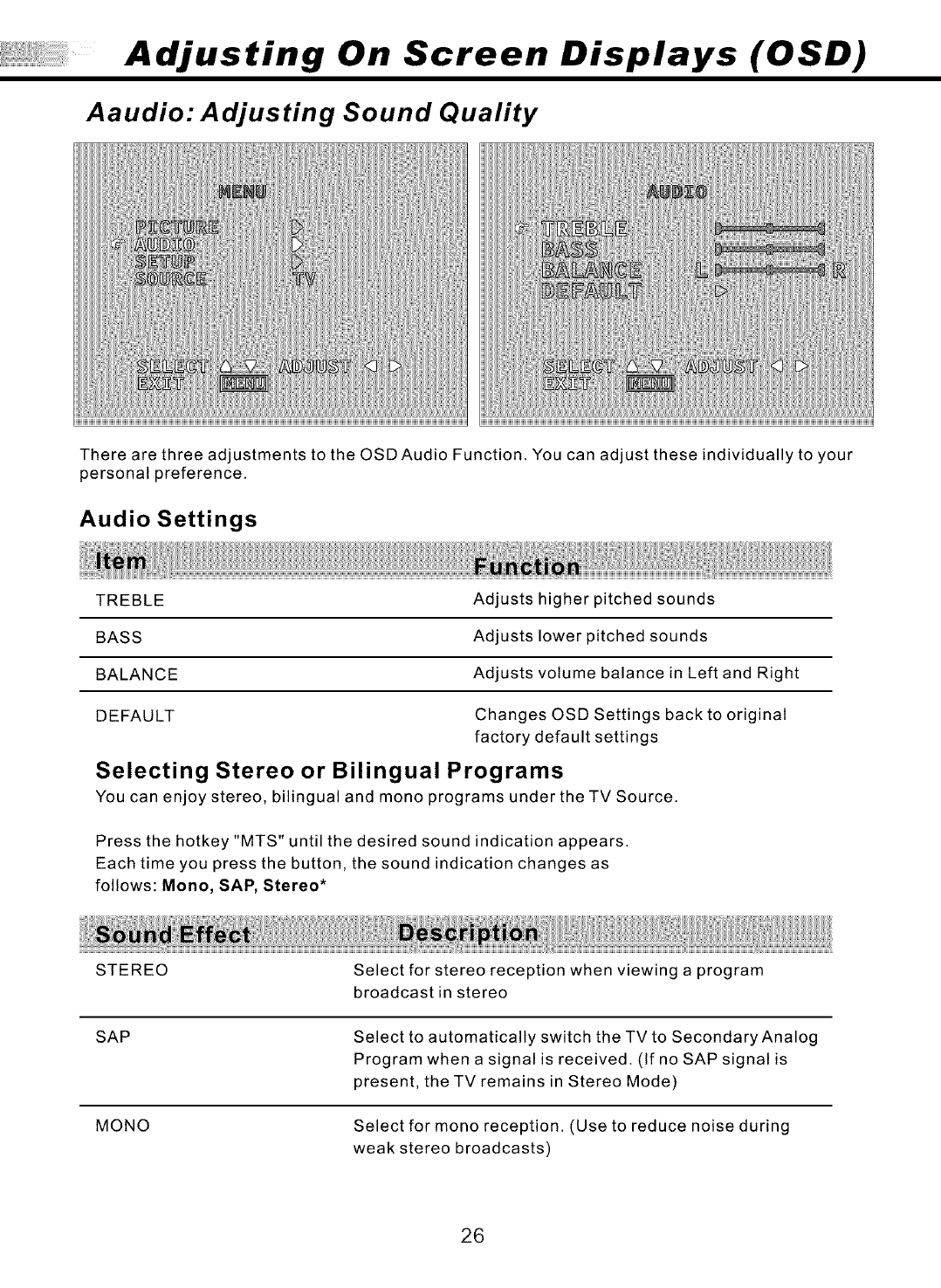
Aaudio: Adjusting Sound Quality
There are three adjustments to the OSDAudio Function, You can adjust these individually to your
personal preference.
Audio Settings
TREBLE Adjusts higher pitched sounds
BASS Adjusts lower pitched sounds
BALANCE Adjusts volume balance in Left and Right
DEFAULT Changes OSD Settings back to original
factory default settings
Selecting Stereo or Bilingual Programs
You can enjoy stereo, bilingual and mono programs under the TV Source.
Press the hotkey "MTS" until the desired sound indication appears.
Each time you press the button, the sound indication changes as
follows: Mono, SAP, Stereo*
STEREO
SAP
MONO
Select for stereo reception when viewing a program
broadcast in stereo
Select to automatically switch the TV to Secondary Analog
Program when a signal is received. (If no SAP signal is
present, the TV remains in Stereo Mode)
Select for mono reception. (Use to reduce noise during
weak stereo broadcasts)
26
Adjusting On Screen Displays (OSD)
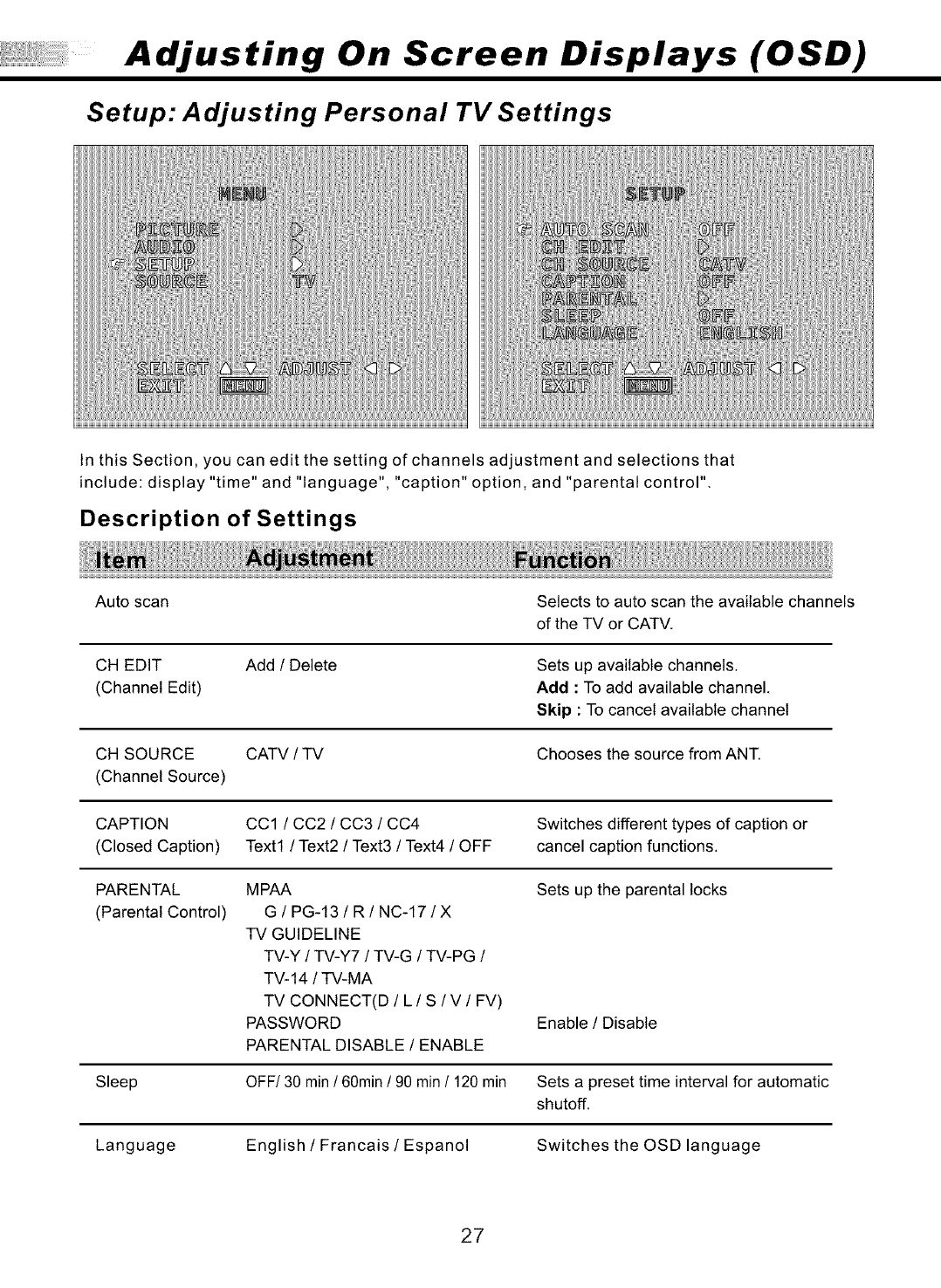
Setup: Adjusting Personal TV Settings
In this Section, you can edit the setting of channels adjustment and selections that
include: display "time" and "language", "caption" option, and "parental control".
Description of Settings
Auto scan Selects to auto scan the available channels
of the TV or CATV.
CH EDIT
(Channel Edit)
Add /Delete Sets up available channels.
Add : To add available channel.
Skip : To cancel available channel
CH SOURCE CATV /TV Chooses the source from ANT.
(Channel Source)
CAPTION CC1 /CC2 /CC3 /CC4 Switches different types of caption or
(Closed Caption) Text1 /Text2 /Text3 /Text4 /OFF cancel caption functions.
PARENTAL MPAA Sets up the parental locks
(Parental Control) G /PG-13 /R/NC-17 /X
TV GUIDELINE
TV-Y /TV-Y7 /TV-G /TV-PG /
TV-14 /TV-MA
TV CONNECT(D /L/S/V/FV)
PASSWORD
PARENTAL DISABLE /ENABLE
Enable /Disable
Sleep OFF/30 min /60min /90 min /120 min Sets a preset time interval for automatic
shutoff.
Language English /Francais /Espanol Switches the OSD language
27
Adjusting On Screen Displays (OSD)
Setup: Adjusting Personal TV Settings
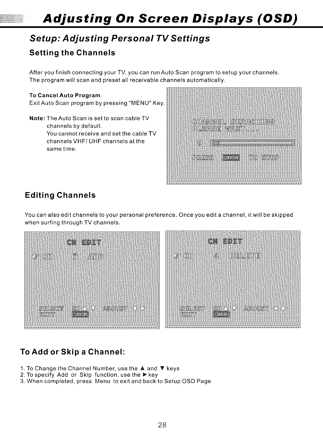
Setting the Channels
After you finish connecting your TV, you can run Auto Scan program to setup your channels.
The program will scan and preset all receivable channels automatically.
To Cancel Auto Program
Exit Auto Scan program by pressing "MENU" Key.
Note: The Auto Scan is set to scan cable TV
channels by default.
You cannot receive and set the cable TV
channels VHF/UHF channels at the
same time.
Editing Channels
You can also edit channels to your personal preference. Once you edit a channel, it will be skipped
when surfing through TV channels.
To Add or Skip a Channel"
1. To Change the Channel Number, use the _, and _' keys
2. To specify Add or Skip function, use the _- key
3. When completed, press Menu to exit and back to Setup OSD Page
28
Adjusting On Screen Displays (OSD)
Setup: Adjusting Personal TV Settings
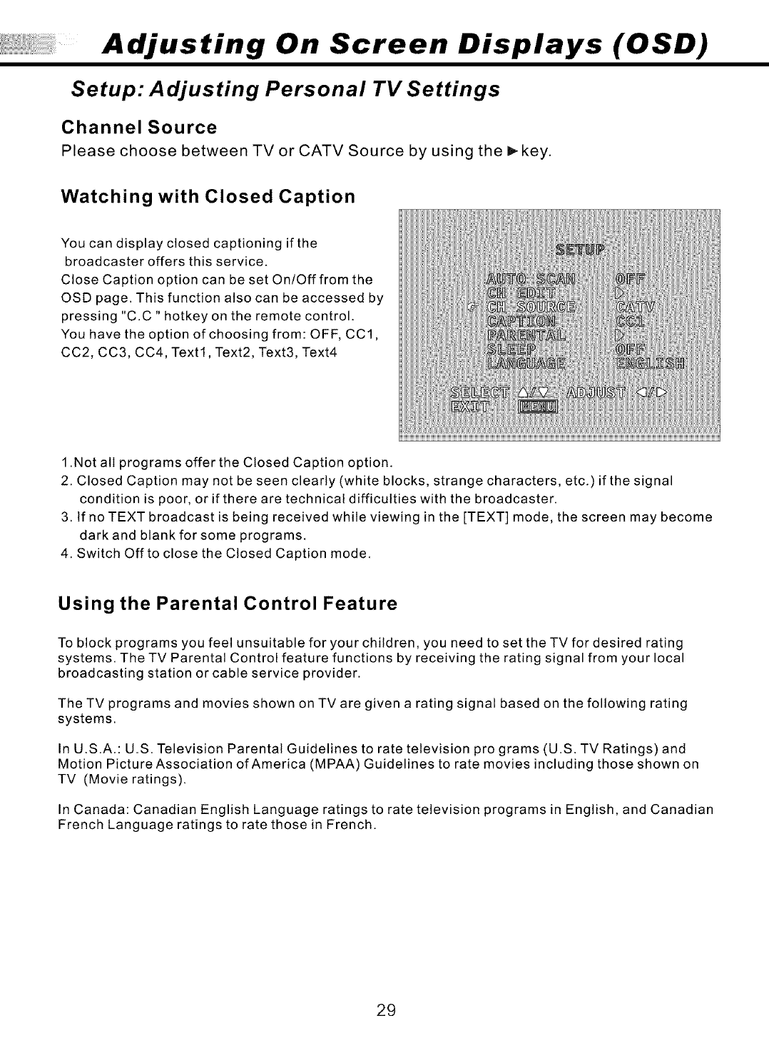
Channel Source
Please choose between TV or CATV Source by using the _key.
Watching with Closed Caption
You can display closed captioning if the
broadcaster offers this service.
Close Caption option can be set On/Off from the
OSD page. This function also can be accessed by
pressing "C.C" hotkey on the remote control.
You have the option of choosing from: OFF, CC1,
CC2, CC3, CC4, Text1, Text2, Text3, Text4
1 .Not all programs offer the Closed Caption option.
2. Closed Caption may not be seen clearly (white blocks, strange characters, etc.) if the signal
condition is poor, or if there are technical difficulties with the broadcaster.
3. tf no TEXT broadcast is being received while viewing in the [TEXT] mode, the screen may become
dark and blank for some programs.
4. Switch Offto close the Closed Caption mode.
Using the Parental Control Feature
To block programs you feel unsuitable for your children, you need to set the TV for desired rating
systems. The TV Parental Control feature functions by receiving the rating signal from your local
broadcasting station or cable service provider.
The TV programs and movies shown on TVare given a rating signal based on the following rating
systems.
In U.S.A.: U.S. Television Parental Guidelines to rate television pro grams (U.S. TV Ratings) and
Motion Picture Association of America (MPAA) Guidelines to rate movies including those shown on
TV (Movie ratings).
In Canada: Canadian English Language ratings to rate television programs in English, and Canadian
French Language ratings to rate those in French.
29
Adjusting On Screen Displays (OSD)
Setup: Adjusting Personal TV Settings
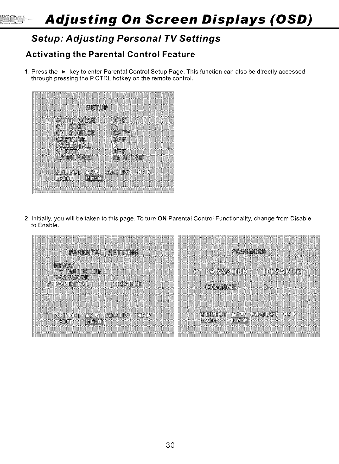
Activating the Parental Control Feature
1. Press the _,- key to enter Parental Control Setup Page. This function can also be directly accessed
through pressing the P.CTRL hotkey on the remote control.
2. Initially, you will be taken to this page. To turn ON Parental Control Functionality, change from Disable
to Enable.
30
Adjusting On Screen Displays (OSD)
Setup: Adjusting Personal TV Settings
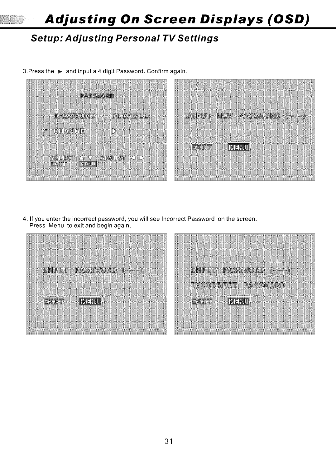
3.Press the _ and input a 4 digit Password. Confirm again.
4. If you enter the incorrect password, you will see Incorrect Password on the screen.
Press Menu to exit and begin again.
31
Adjusting On Screen Displays (OSD)
Setup: Adjusting Personal TV Settings
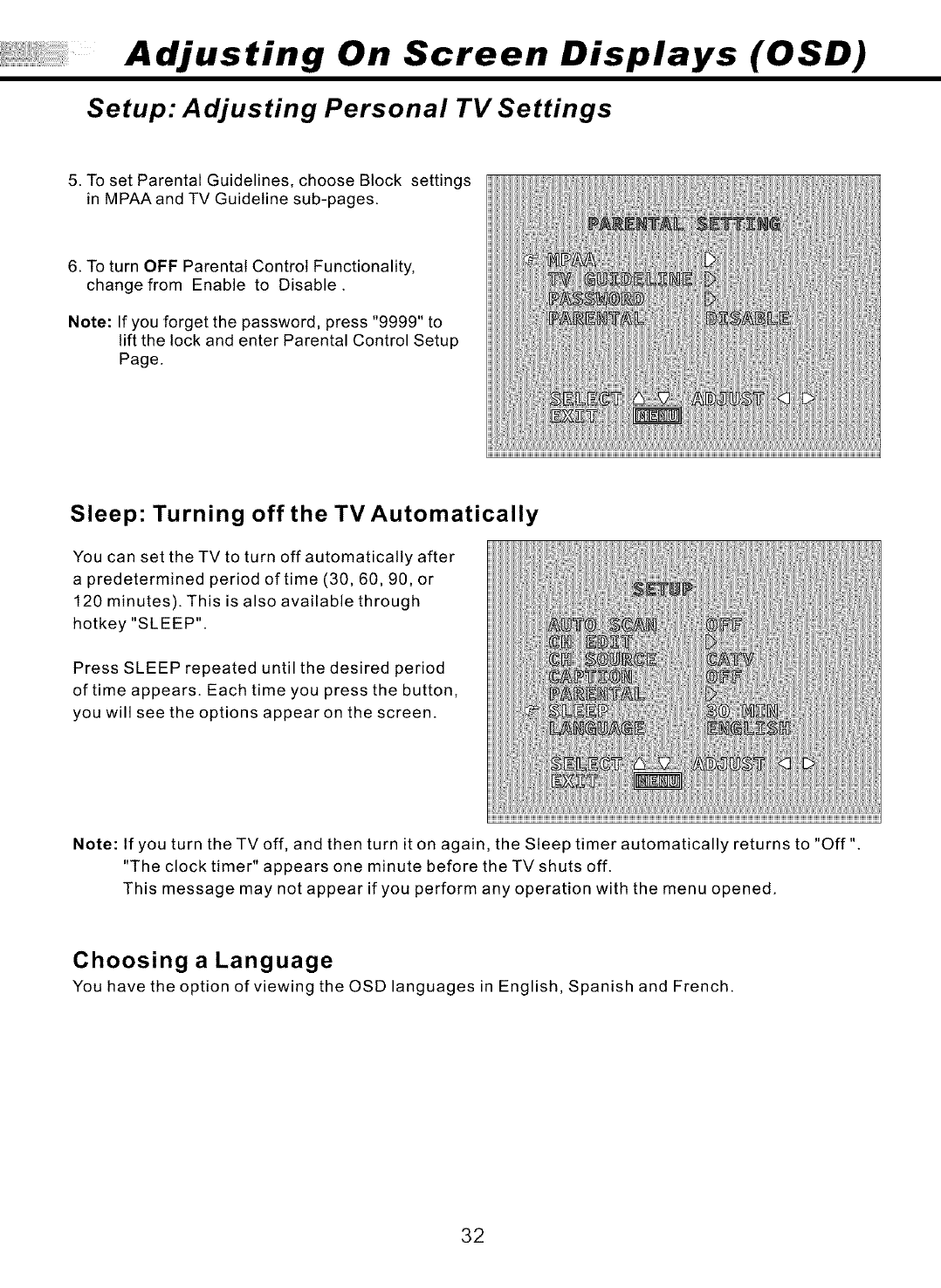
5. To set Parental Guidelines, choose Block settings
in MPAA and TV Guideline sub-pages.
6. To turn OFF Parental Control Functionality,
change from Enable to Disable.
Note: If you forget the password, press "9999" to
lift the lock and enter Parental Control Setup
Page.
Sleep: Turning off the TV Automatically
You can set the TV to turn off automatically after
a predetermined period of time (30, 60, 90, or
120 minutes). This is also available through
hotkey "SLEEP".
Press SLEEP repeated until the desired period
of time appears. Each time you press the button,
you will see the options appear on the screen.
Note: If you turn theTVoff, and then turn it on again, the Sleep timer automatically returns to "Off"
"The clock timer" appears one minute before the TV shuts off.
This message may not appear if you perform any operation with the menu opened.
Choosing a Language
You have the option of viewing the OSD languages in English, Spanish and French.
32
Adjusting On Screen Displays (OSD)
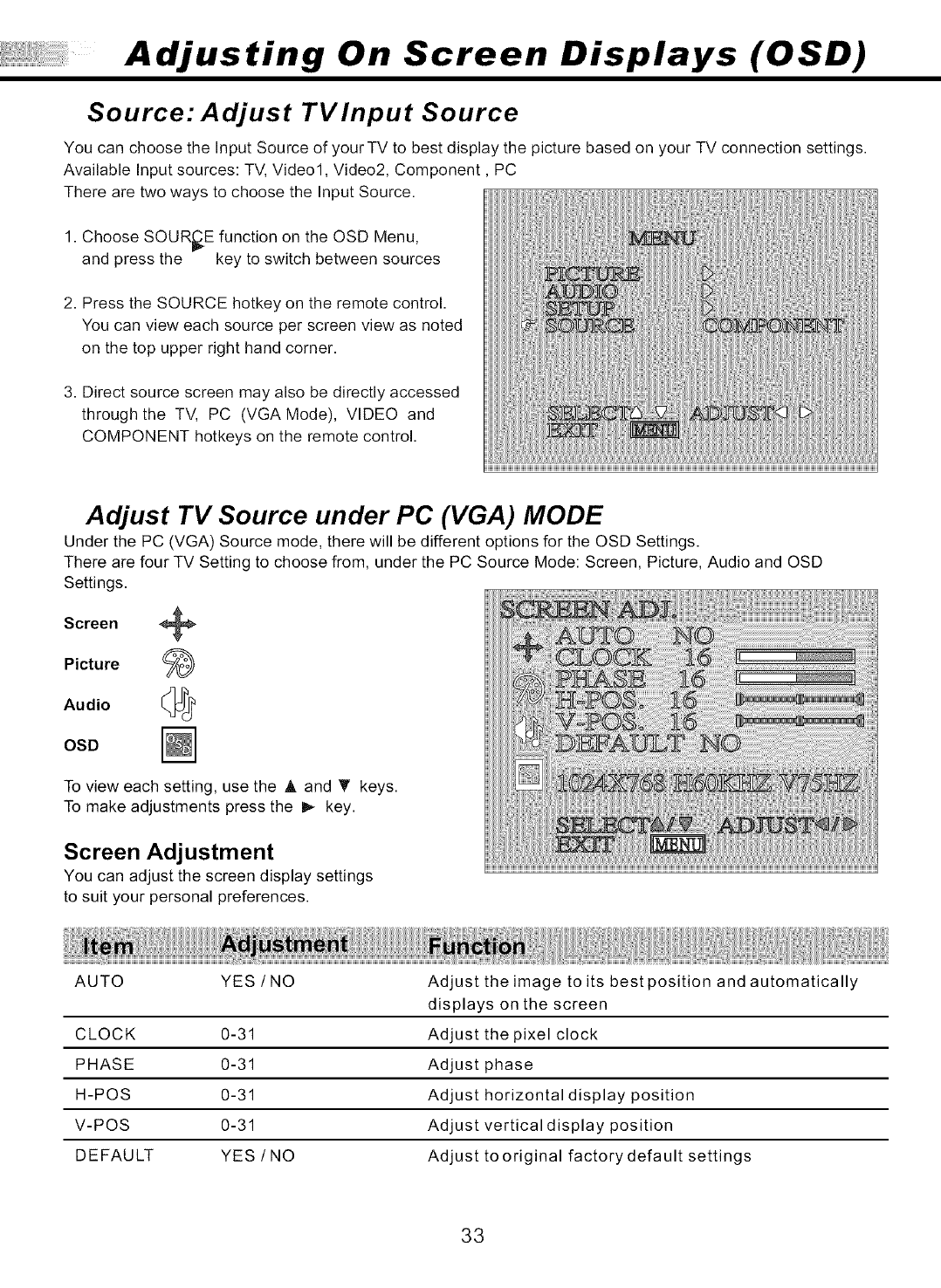
Source: Adjust TVlnput Source
You can choose the Input Source of your TV to best display the picture based on your TV connection settings.
Available Input sources: TV, Video1, Video2, Component, PC
There are two ways to choose the Input Source.
1. Choose SOURCE function on the OSD Menu,
and press the key to switch between sources
2. Press the SOURCE hotkey on the remote control.
You can view each source per screen view as noted
on the top upper right hand corner.
3. Direct source screen may also be directly accessed
through the TV, PC (VGA Mode), VIDEO and
COMPONENT hotkeys on the remote control.
Adjust TV Source under PC (VGA) MODE
Under the PC (VGA) Source mode, there will be different options for the OSD Settings.
There are four TV Setting to choose from, under the PC Source Mode: Screen, Picture, Audio and OSD
Settings.
Screen +
Picture
Audio _
OSD
To view each setting, use the A and T keys.
To make adjustments press the I_ key.
Screen Adjustment
You can adjust the screen display settings
to suit your personal preferences.
AUTO YES/NO
CLOCK 0-31
PHASE 0-31
H-POS 0-31
V-POS 0-31
DEFAULT YES /NO
Adjust the image to its bestposition and automatically
displays on the screen
Adjust the pixel clock
Adjust phase
Adjust horizontal display position
Adjust vertical display position
Adjust to original factory default settings
33
Adjusting On Screen Displays (OSD)
Choosing TVInput Source
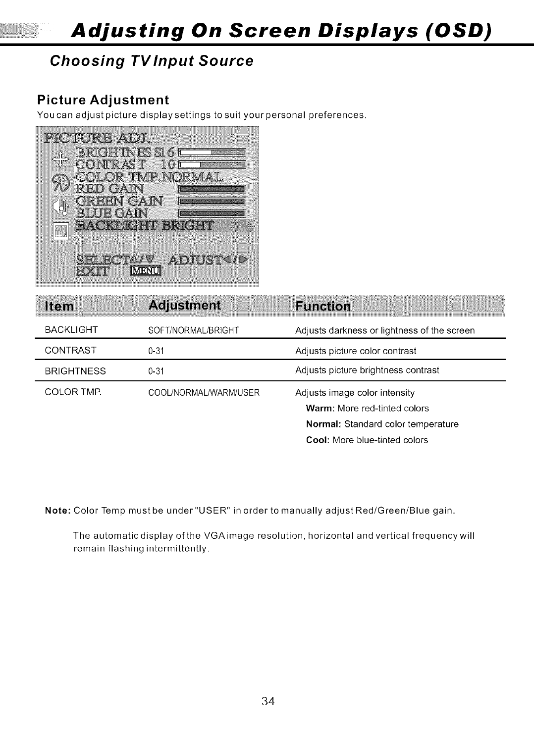
Picture Adjustment
You ca n adjust picture display settings to suit your personal preferences.
BACKLIGHT SOFT/NORMAL/BRIGHT
CONTRAST 0-31
BRIGHTNESS 0-31
COLOR TMR COOUNORMAL/WARM/USER
Adjusts darkness or lightness of the screen
Adjusts picture color contrast
Adjusts picture brightness contrast
Adjusts image color intensity
Warm: More red-tinted colors
Normal: Standard color temperature
Cool: More blue-tinted colors
Note: Color Temp mustbe under "USER" in order to manually adjustRed/Green/Blue gain.
The automatic display of the VGAimage resolution, horizontal and vertical frequencywill
remain flashing intermittently.
34
Adjusting On Screen Displays (OSD)
Choosing TVInput Source
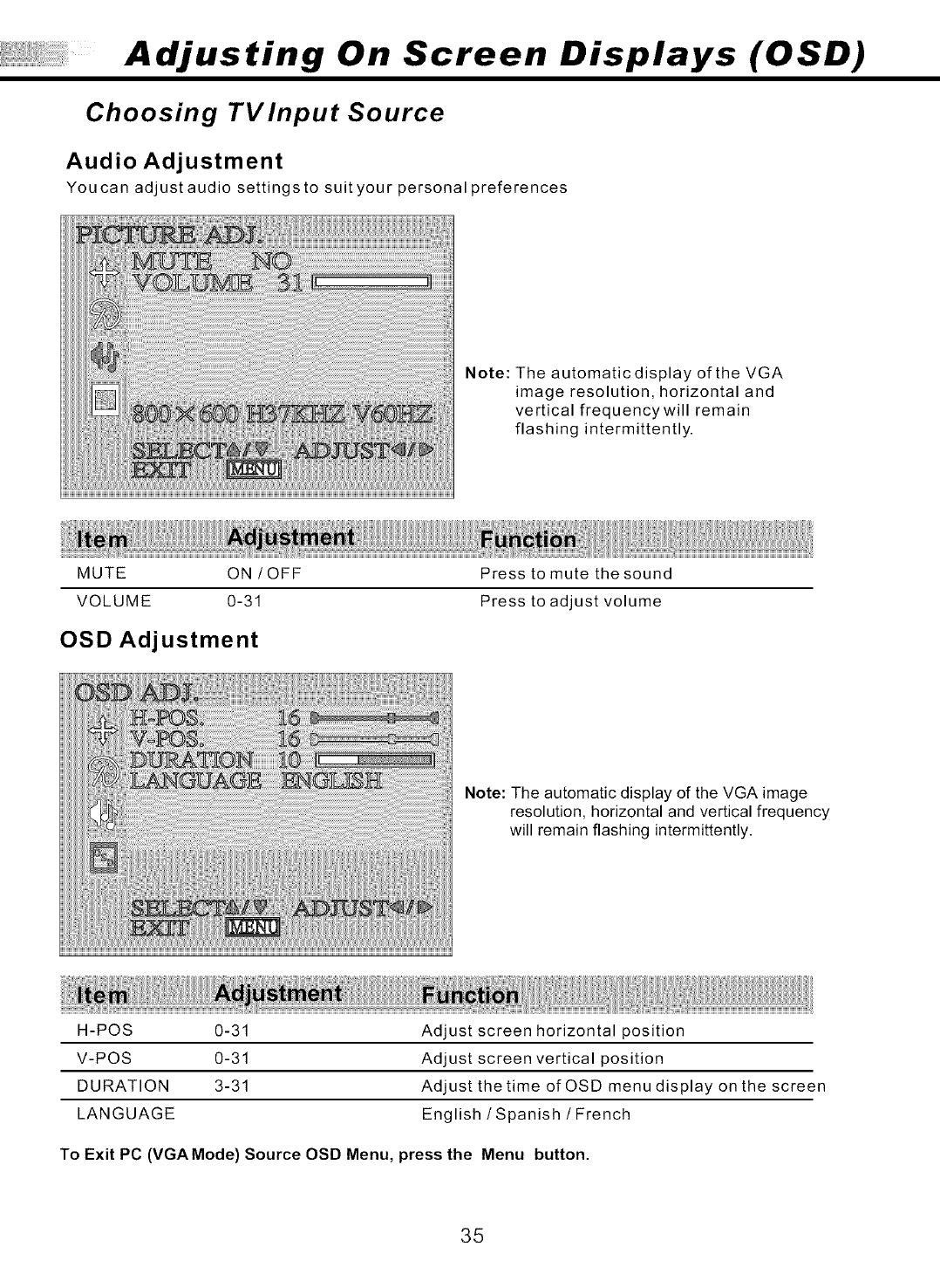
Audio Adjustment
You can adjust audio settings to suit your personal preferences
Note: The automatic display of the VGA
image resolution, horizontal and
vertical frequencywill remain
flashing intermittently.
MUTE ON /OFF
VOLUME 0-31
OSD Adjustment
Press to mute the sound
Press to adjust volume
Note: The automatic display of the VGA image
resolution, horizontal and vertical frequency
will remain flashing intermittently.
H-POS 0-31
V-POS 0-31
DURATION 3-31
LANGUAGE
Adjust screen horizontal position
Adjust screen vertical position
Adjust the time of OSD menu display on the screen
English/Spanish /French
To Exit PC (VGA Mode) Source OSD Menu, press the Menu button.
35
Troubleshooting
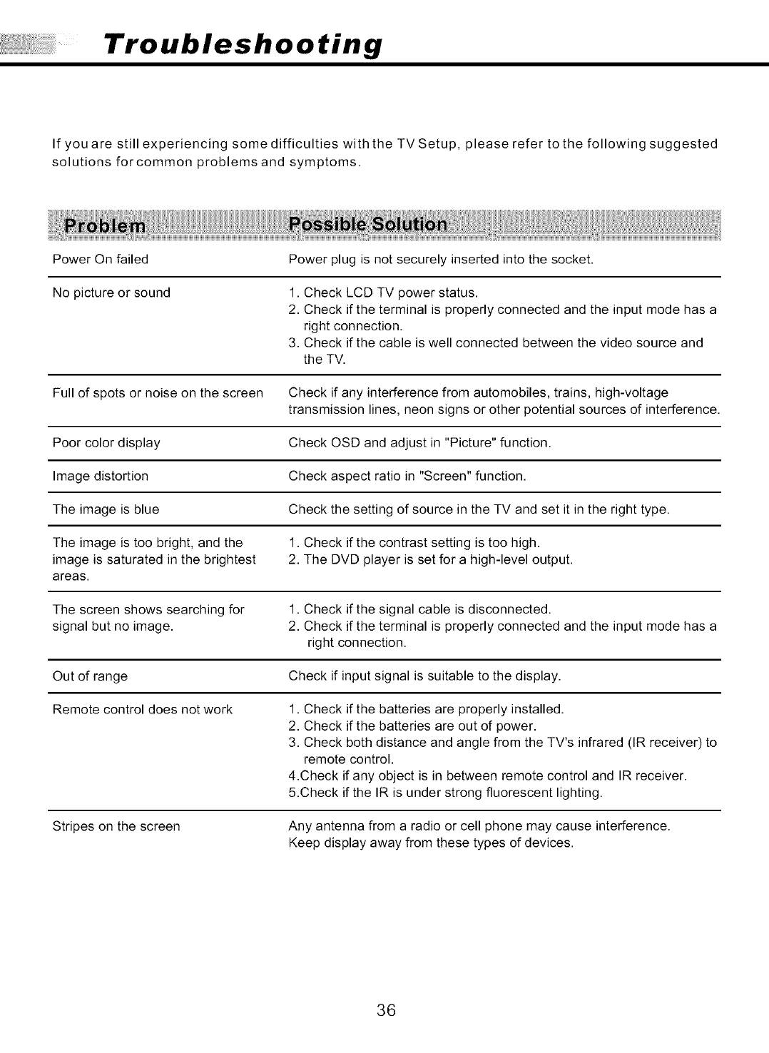
If you are still experiencing some difficulties with the TV Setup, please refer to the following suggested
solutions forcommon problems and symptoms.
Power On failed Power plug is not securely inserted into the socket.
No picture or sound 1. Check LCD TV power status.
2. Check if the terminal is properly connected and the input mode has a
right connection.
3. Check if the cable is well connected between the video source and
the TV.
Full of spots or noise on the screen Check if any interference from automobiles, trains, high-voltage
transmission lines, neon signs or other potential sources of interference.
Poor color display Check OSD and adjust in "Picture" function.
Image distortion Check aspect ratio in "Screen" function.
The image is blue Check the setting of source in the TV and set it in the right type.
The image is too bright, and the 1. Check if the contrast setting is too high.
image is saturated in the brightest 2. The DVD player is set for a high-level output.
areas.
The screen shows searching for 1. Check if the signal cable is disconnected.
signal but no image. 2. Check if the terminal is properly connected and the input mode has a
right connection.
Out of range Check if input signal is suitable to the display.
Remote control does not work 1. Check if the batteries are properly installed.
2. Check if the batteries are out of power.
3. Check both distance and angle from the TV's infrared (IR receiver) to
remote control.
4.Check if any object is in between remote control and IR receiver.
5.Check if the IR is under strong fluorescent lighting.
Stripes on the screen Any antenna from a radio or cell phone may cause interference.
Keep display away from these types of devices.
36
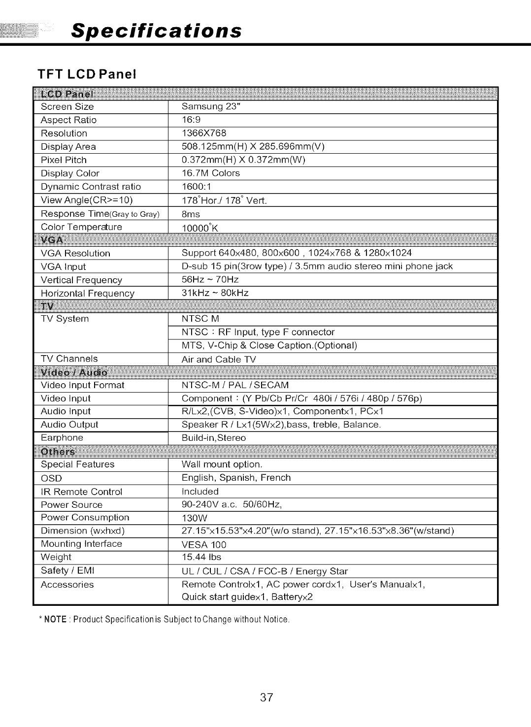
Specifications
Aspect Ratio
Resolution
Display Area
Pixel Pitch
Display Color
Dynamic Contrast ratio
View Angle(CR>= 10)
Response Time(Gray to Gray)
Color Temperature
TFT LCD Panel
Screen Size Samsung 23"
16:9
1366X768
508.125mm(H) X 285.696mm(V)
0.372mm(H) X 0.372mm(W)
16.7M Colors
1600:1
178°Her./ 178 ° Vert.
8ms
10000°K
VGA Resolution Support 640x480, 800x600, 1024x768 & 1280x1024
VGA Input D-sub 15 pin(3row type) /3.5mm audio stereo mini phone jack
Vertical Frequency 56Hz - 70Hz
Horizontal Frequency 31kHz - 80kHz
TV System NTSC M
NTSC : RF Input, type F connector
MTS, V-Chip & Close Caption.(Optional)
TV Channels Air and Cable TV
Wa di ....
Video Input Format NTSC-M /PAL/SECAM
Video Input Component : (Y Pb/Cb Pr/Cr 480i /576i /480p /576p)
Audio Input R/Lx2,(CVB, S-Video)x1, Componentxl, PCxl
Audio Output Speaker R/Lxl (5Wx2),bass, treble, Balance.
Earphone Build-in,Stereo
Special Features Wall mount option.
OSD English, Spanish, French
IR Remote Control Included
Power Source 90-240V a.c. 50/60Hz,
Power Consumption 130W
Dimension (wxhxd) 27.15"x 15.53"x4.20"(w/o stand), 27.15"xl 6.53"x8.36"(w/stand)
Mounting Interface VESA 100
Weight 15.44 Ibs
Safety /EMI UL /CUL /CSA /FCC-B /Energy Star
Accessories Remote Controlxl, AC power cordxl, User's Manualxl,
Quick start guidexl, Batteryx2
* NOTE : Product Specification is Subject t0Change without Notice.
37
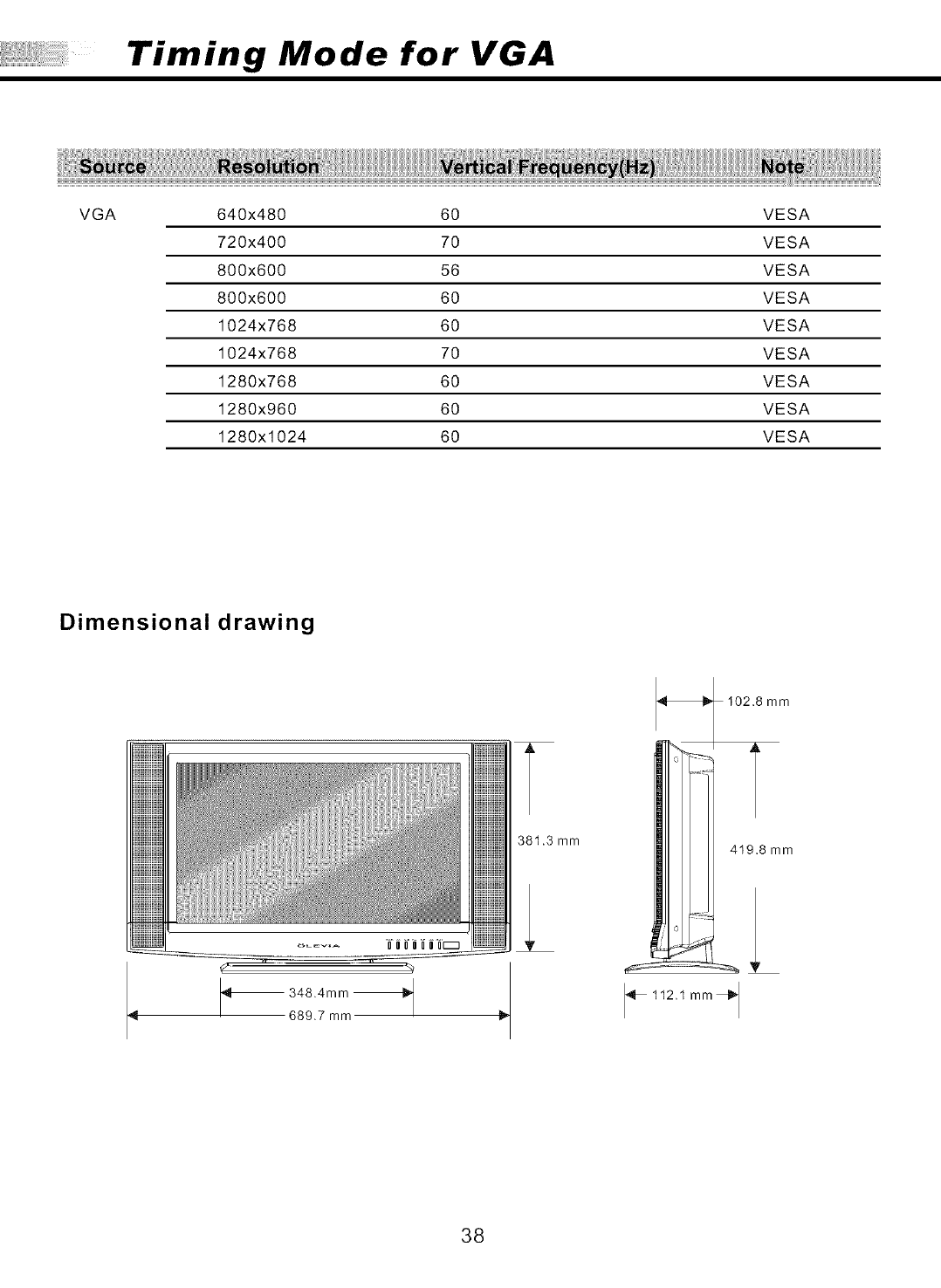
Timing Mode for VGA
VGA 640x480 60 VESA
720x400 70 VESA
800x600 56 VESA
800x600 60 VESA
1024x768 60 VESA
1024x768 70 VESA
1280x768 60 VESA
1280x960 60 VESA
1280x1024 60 VESA
Dimensional drawing
OOOOOOO[_
_ 348.4mm _
689.7 mm
381.3 mm
102.8 mm
419.8 mm
_ 112.1 mm_
38

Pixels Policy
Syntax's D.O.A. Policy for LCD TVs for
Defective Pixels on LCD Panels
(Applicable tothe LCDTV soldwithin USA& Canadaonly)
Syntax TM LCD TVs are evaluated at a distance of approximately 50 centimeters
(approximately 20 inches) between the LCD panel and the eyes of the user ata 90 degrees
viewing angle. All LCD panels have been tested to ensure they comply with our factory standards.
Our evaluation is based on the number of defective pixelsand the distance between any two
defective pixels. Bright dots are dots that appear bright and unchanged in size when a LCDTV
screen displays under a black pattern; dark dots are dots that appear dark and unchanged in size
when aLCD TVscreen is displayed under pure red, green, or blue patterns( defectivepixels ).
Adjacent dots are dots located directly next to each other.
Customers are required to check their LCD panel immediately after purchase. To identify defective
pixels, the LCD panel should be examined under normal operating conditions as mentioned above,
preferably in its nativedisplay resolution, and with a 90degrees viewing angle.
A LCD TVwill be considered dead on arrival(D.O.A.) with regards to defective pixelson theLCD panel
when anyone ofthe following criteria is met:
Atotal of 7 defective pixels including both brightdots and dark dots are present (the typical
30 LCDTelevision screen has 16.7 million pixels),or
2 or more pairs of adjacent bright dots are present, or
3 adjacent bright dots are present, or
3 adjacent dark dots are present.
In view of customers' concerns about dead pixels, Syntax would like to address that defective pixels
are not ultimately avoidable with the current LCD industry standard panel manufacturing processes.
We always strive to improve our technology and minimize the chance of occurrence of defective pixels
by applying strict screening processes in our factory production processes. However, Syntax cannot
guarantee thata return unit to our customers will be 100% free of defective pixels.
For questions, please call our toll free service number in the USAat 888-SYNTAX-8.
"At SyntaxGroups, a satisfied customer is our most important focus. "
39
