ONKYO Receivers Manual L0311320
User Manual: ONKYO ONKYO Receivers Manual ONKYO Receivers Owner's Manual, ONKYO Receivers installation guides
Open the PDF directly: View PDF ![]() .
.
Page Count: 28
Ol_r I,t'tx,"O
TX-8511
Audio Video Control Receiver
Instruction Manual
= ©
[=2 ====
@ I_T" _H 0 0 0
I_, L__J
!= ©f I
j
© _ T I I I _000 I
J
European moOels Otr-£1 mi2 rJels
_WIr_TS
Features .............. '--*_1 _" ''_ ........................ 2
Precautions ................................................ 4
Supplied accessories ............................... ;-. 4
Before operating th_ trait ......................... 4
Control positions and p.mm_ ........... ........ ,-. 5
Making system connections ............... ;...... 7
Connecting the power ............................. !2
Basic okxg"ations ........................ :............... t3
Receiving rtmmns .................................... 15
Re,ceivmg RDS (O_fe_-_ a_l.
some othermodds) ..:................................... t8
Entenng station name_. .............................. 20
Recording asoure._q,;.,.i.r,_ ........... 2-.2..21
Os'mg TAPE-2 MONITOR ....................... 23
Connection f&" Mul_-Room
Multi-Room Remote Control .. ............ -....26
Troub_i_tg guide .............................. 27
Speeifieadotas ......... ........ :.......................... 28
Thank you ,or theOnk>]
TX-8511 Audio Video Control Receiver.
Please read this manual lhoroughly before making con-
ii_cboll_, and operttul/g tile onH.
Following the instructions in thls manual will enable
you to obtain optimum pcrlormaoce anu Ntening
en.loyment from your new Recmver
Please retain this manual for {ulure reference.
Note to CATV system installer:
• l'his reminder is provided to call Ihe CATV _,ystcm insmller's
attention to Section 820-40 of the NEE which provmes guide-
linch lbr proper gr_mncu tg and. in par[lcular_ bIN?tit/tiN tl?at 111_2
cable ground shall be conllectell _/i me grtmnalng _5_tem of the
bmlding, as close to the point ot cable entry as practical
2
Features
• Power output
USA & Canadian models:
100 watts per channel, min RMS. al 8 ohms. both
channels driven from 20 Hz to 20 kHz. with no
more than IL08% THD.
European models:
2×100 watts at 4ohms. 1 kHz iDINI
Asiau models:
2_,130 watts at 4 ohms, 1 kHz (EIAJ)
•Discrete output stage circuits for wue high-current.
low-impedance drive
•Costly, high-quality parts such as large power tran-
sistors, an oversized isolated lransfilrmer and heavy-
duty extruded heat sink makes it possible to accu-
rate!y and effnrtD_!y drive 4-ohm speakers (rare !or
areceiver
•Multiroom Remote System capabilit_ IUSA models
are compatible with Xantech r_ aeeessoriesl
•4 Audio and 2 AV inputs
•A/B Speaker selector and outputs
• Video and cassette tape dubbing capability
•Selective tone control
•2-Mode APR iAutomatic Precishm Reception) (local/
DX. autoimono_
•30 FM/AM random presets
•Preset scan tuning
•3 Station group presets 110 stations per group) with
character naming
•RDS _itb PS. PTY. RT, TP (European and sume
other models only_
•Direct access tunin=
•Motor-driven, precision volume control
•Headphone jack
•Audit, mute, sleep timer ivia remote)
• Battery-free memory backup
•New non.resonant feet
•New slip-free rotary volume knob
•I'_! Compatible remote control
*XANTECH is a registered trademark of Xantech Comoratmn.
IUSA ,.
Memory Preser_.atJon
rI_]l_ lllll[ does IiOl require llletllOr _, DlgSCl_[tlOtl batteries. Abulk ill
memory power b&ck lip System preser'_e_ t]_e COrlt_tl_S oI rrte rllerll
_r_ Ourln,1 power }adore8 alld everi _x_h_ii Ih_ {lil[_ {_ unpklgged, Phe
Ulllt inLtb[ b_ p]lA_g_tl in order to ch;lrg_ tflc D_CK up _;y [ellrl.
The memory pre_er\ra[io_ period direr th_ unit ha_ t_*en unpltlgged
•_ar_es del[_ndila s off cli_nate and _ _lncnt ot tile _IIIL UII _he a_,cr -
_lge, Illemor_ cO_ll_fl[_ _[e proie_l_O over a 13_rlOQ oi 3 lew WeeR
after the last 11me the tmn na_ r)een lnph]gged. ]ht_ period t,
_horter when the ulut is exposed Io a hi_zhl 5 humid climate
•For models having a power cord with apolarized ping
CAUTION: "to PREVENT ELECTRIC SHOCK. MA'ICH
WIDE BLADE OF PLUG TO WIDE SLOT. FULLY INSER].
• Sur te_ modele_ dora la fiche est _olari_e.
ATTENTION: POUR £VITUR t.ES CHOCS tLBC-
TRIQUES. INTRODU1RE LA I.AML LA PLUS LARGE DE LA
FICHE DANS LA BORNE CORRESPONDANTE DE LA
PRISE ET POUSSER .II/SQU'AU FDND
Declaration of Confl)rmity
We, ONKYO EURDPE
ELE('TRONICS GMBH
INDUSTRIESTRASSE I8/_0
821 It) GERMERING.
GERMANY
declare in own responsibility, that tllU ON K Y() lloduct described
ill thi_ lIiMrtlCliorl manila] is in coli_p lance wlth the correspomhn_
mchn real standards such as EN55013,EN5502O.EN60555 2.
EN60065
GERMERING.GERMAN Y _(_
H YAMAZO_
ONKYO El ROPE ELECTRONICS GMBH
Replacement and mounting o_ an AC plug on the power supp_
cord of this unit should he perl)rmed only by _tualilied service
personnel
IMPORTANT:
The w_res in the mains lead are co{outed in accordance with the
lMlowing code:
Blue: Neutral
Brown: L_ve
As the coiours of the wires in the mains lead of tins apphance may.
no_ correspond with the colour_d m_uking_ identifying the _ermi
nats ill your piLlS, proceed as follows:
The wire which is coloured BLUE must tx_cOIllleCt_d to the ternu-
hal m the plug which is marked wltt] t_.e letter N o_ colom'_d
BhAUK
llle w]Ie wnmh ts cohmred BROWN mast be connected to file ter-
minal in lhe pm_ which is mar_eo w*m the letter L or coioured
RED.
IMPORTANT
A5amp fuse is fitted in thl_ p]ug, Shoud th_ fuse need to be
replaced please ensure that the reNacement Ihse has a lfiHI/g of 5
aml_s and that _t is app'oved h3 ASTA or BSI to BS /362, Check
lot the ASTA mark or the BSI mark on the _,ay of the lhxc
IF THE FITTED MOULDED PLUG IS UNSUITABLE [:OR
TIlE SOCKET OUTI.ET IN YOUR HOME THEN THE FUSE
SHOULD BE REMOVED AND THE PLUG CUT OFF AND
I)ISPOSED t)F SAVE[ Y '1 HERE IS A DANGER OF SEVERE
ELECTRICAl. SHOCK IF 'IHE CIJ F OFF PLUG IS INSER i'ED
INTO ANY 13 AMP SOCKE'[
is: ...... 4_._* _ ............. i, .L*- .-I I .....
"WARNING"
-'TO REDUCE THE RiSK OF FIRE OR EI.E('TRI(" S!I(X'K
Dr) Nt)I EXPOSE THIS APPI lANCE TO RAIN OR MOIS
TI-RE
CAUTION:
"-TO REF)L CE THV RISK OF EEE('TRIC SHOCK, I)O NO'I
_EMOVE ('()\ER OR BAUK_ NO USER SERVICI-,ABEE
_,\RTS INSIDE. RhI_ER SERViCiNG 1"O _)L AI,[FtED SER-
VIUE PERSONNEL
WARNING
ro Derson_
•The exciamatlor OOlr/i w_inm an equl aleral mangle
IS intone€ _o aer_ [rl0 user [o UI_ 3feset?c_ Ol
_portant opo¢'shR_ _no mfltntsnar]G_ (sel%'lciq_)
rls[ructlOnS in tDe it_raluro accor_p_lnyln 9 ire
oro,2 u¢1
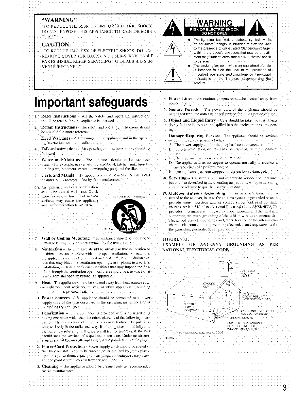
Important safeguards ,, PowerLines_,,,_r.n_, An ...... ran,.2m_a_,hoaldb,'lo,-+,,cd._,,_a.,.r_m
J5 Nollttse pt.,riods - The [u)_!r c_ru o] tn_' appliance _noum oL
I Read Instructions &ll ttlc _alL[_ arid OD¢l'a[lllg 111_1"11¢_1On5 UllplLIg_.ed f1Oi_l the olltl_ _x,h_u !_:ft I_Dtls'c_r] _or _/ ll_ilg 13¢flod _.)_ tln3c
_nomd r_c _cao bciure ule ,t_pthtacc i_up,laird, _ Object alld Liquid Entry Care _hould be takeu _o thai obje_
Jo m_Iflfll and li=uld_ zre nut _ilk'd inlo the _'nclu_t_rcthrough upen-
7 Rt*_in ln_trul*tions Tht? _,lt,_l_ ,lnd l IIL'fI_IH3_ IllSlyU( llt,R_ :_rlOLIIL
FIGURE 73.1:
EXAMI'LE OF ANTENNA GROUNDING AS PER
NATIONAl. ELECTRICAL CODE
,_NTFNNA
_EAD IN
Power Sources -The ap]3liancc should be conilected m ,_ p_wer
,_tpp_'¢ onl_ C'I lrl¢ I _¢ de',crtbt'd lfl ItqC itp_tallll_ lilMl'Ugllon£ i_l a5
tnarked on the app ianct"
Polarization l_ me ap] +mtt = _mwncn wlln a polaltze:l plug
nav]n_ _e hlad¢ _,_dc '¸ lhatt the _,theL :_lva_c t c_d the _l]owJl o it,rr_t_
_ti_n "lh_ - _OI_UlZ_IHOn ol :n_ plU_ I_ _ _,_lte:_ J_l[llr¢2 l'h_2 pOl_ffl/_.o
_tu_ _' |1 orllv t_t th_ nuth't one _a_ l[ the ping _oe_ riot tlI Iull_ ln[o
lrlC Otlllpl tr' r_x.cr,,ln_ il [3 Lh_l_ _f. _,t_l] LrtJLtb_c lllSCl!lllg II t : l_,_:i
should Seek the _¢r;tc_5, (_ a __all[ted _]_ctr]_l_n. h'l/d_r ii1_ c{reum
stance, s?lO_ld uB" tl_I 3itenlp| to d_Cal /h_ _o/_r]z_lti(m of the p_u_
%E qAT ONAL E EUTR _L CODF
52898A
_WCII SEItd[CE G_ UND N¢;
ELECTRODE SYSTEM
NEC &RT 2_ p_ ¢)T _4
12 Power-('ord Proteetiou - Power+supp Uxotds _h/)uld bc routed,
[ha_ [h_ _, _1_ tlol hk_] to be _alk_d oil Ol )lf_ct!_l Dy _t_'m_ p auc_
lil_ l_c _11I v_twi,z tt_\ L_\lt iroln illC DDIlanCc
13 Cielt]liIIM The aDl?liallCC' bhouJt] 1)_ d_ll_d O]l/X_ Nh /eCI)l_/llJClid_d
_ I_ _ ll/dItUf_gtttft'r
3
Precautions Supplied accessories
LWarranty Claim
You can find/he so]iM numbci _n the rear _amq. In ca_c Fwar-
rallt_ C_alII/, please report this rtlllrlnt_r.
2. Recording Copyright
Rec'_mmlg of cop)rig,/fee rllaiorial for other than pcrsonm tlS,e 1_,
illegal without penm_sum o[ rim copyright h_kler.
3. AC Fuse
The fuse is located inside the cha_sl_ and is m_t u_er-scrviccahle.
lI l_owei ctue5 ]lot cotTqe on, COllga_21your Ollkyo authol ized _,el'rice
h[_l] OH
4. Care
Frl)][i [IHI_ [Q [lille 5U should wipe 1he fHHll and rear p;llIelh tll/{]
tile cabinet %'l[h _1 SOl[ ch)tl] _or heavier dtrL oalnpelI a '_o11 clokh
ill _1 We_lk !,t)ltltltln t)f iiuld d_t_r_llL _iIIU _._at*l, wring tt out dry.
anu _pe off the dirt. Following th_s. dry nnmematel with a clean
cloth Do not u_e rough iTtatcrl_d, thinm-r_, alcohn] or ether cheml-
C;tl %olvt*nls tit Llotrl_ MIWc tle_e coil It +lain i_e the fir_Jsh or
remove me t"reel letlerirmg
5. Power
WARNING AMIoo_amenna 111
BEFORE PLUGGING IN THE LNJT FOR THE FIRST TIME.
READ THE R)LLOWIN(I SECTION CAREFULLY
• Some modela oiL" CleSl_llt'd {or u_l, (lilly Wltl] [De pov, cr stlpp/y
_olta_e of the region where they are solc
>mopean and Austr,dian mode/s'AC 230_,2_OH_
U.S and Cana&an m_dels AC 120%.60Hz
World,Mde m_×tel AC 220-2 _0_¢7]20V s_ikhahle.
N)/6Ollz
()tile At" 220\ hlibl,
•Voltaire St'ltxtor/Rear Panel
Worldwide models are eqtnpped with a v_ltage selector to con
form to local pm_er sup_hes, Be sure to set m>; ,_itch [o
match the _oltage of the po_er supply 11]_tlur area before
pmggmg in me uml See below Modelb withoul a voltage
S_l_'ctoI Call 0111 x [3e used In area_ whele tile Dower Mlpp/} i
/he _mle as that otthe uldl
The power does not _hut off completely by JUStturmng me
power of I So power eoid should be retrieved from AC outlet
WFR2ll I/Ot ill ElSe fill a pl'OlOll_e{l tim(
Remote control RC-329S l-
Battery _size AA R6 or UM-31 f21
Worldwide a_d some other models
75/300 ohm
_liqforlrl_ ia01_D_or ( ]
T-shaDed FM antenna
WortdwtcJe model on.,
Conversmr plug
Shape may vary
aceorolng lO lrte area
wher8 Durcrl_s_o 1
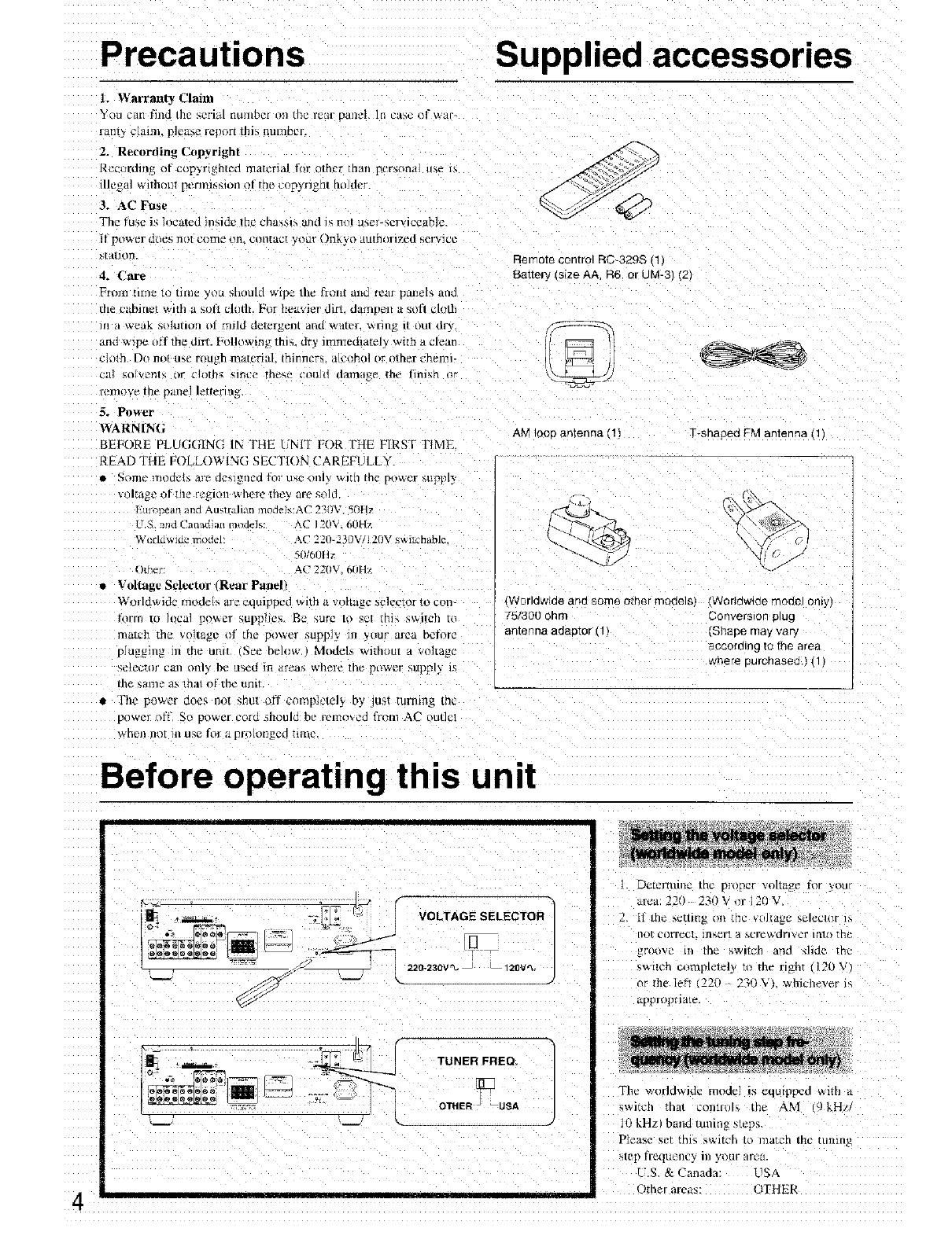
Before operating this unit
-- \
VOLTAGE SELECTOR
2120V%
TUNER FREQ.
OTHER _USA
Delta'mine the proper voltage for vou
area: 220 23!) V or 120 V.
P Ii lh_ _ettirI_ 11_ U_C VLIJI_._C beh$ClOl l_
IO[ t2OITeCt,iilsert a screwdriver late the
groove in the switch and shde the
switch c_mplclely re me right (120 \
_ tile let_ 220 230V} whichever ,.
appropr late.
The worldwide model is equipped with a
_wircll "hat contro[_ ne AM 9 kH
10 kHzl band tunin_ step.
Please set thl_ switch /0 match the tuning
step IrequellC_ In your are_
U.S. & Canada: - 1SA
Other areas: OTHER
Control positions and names
3ther than USA & Canadian mode
5 6
21
8 9 10 11 12 13 14
USA and Canadian mode
20 19 18 17 16 15
1
Display
ab c d e fh i k I
0 n m
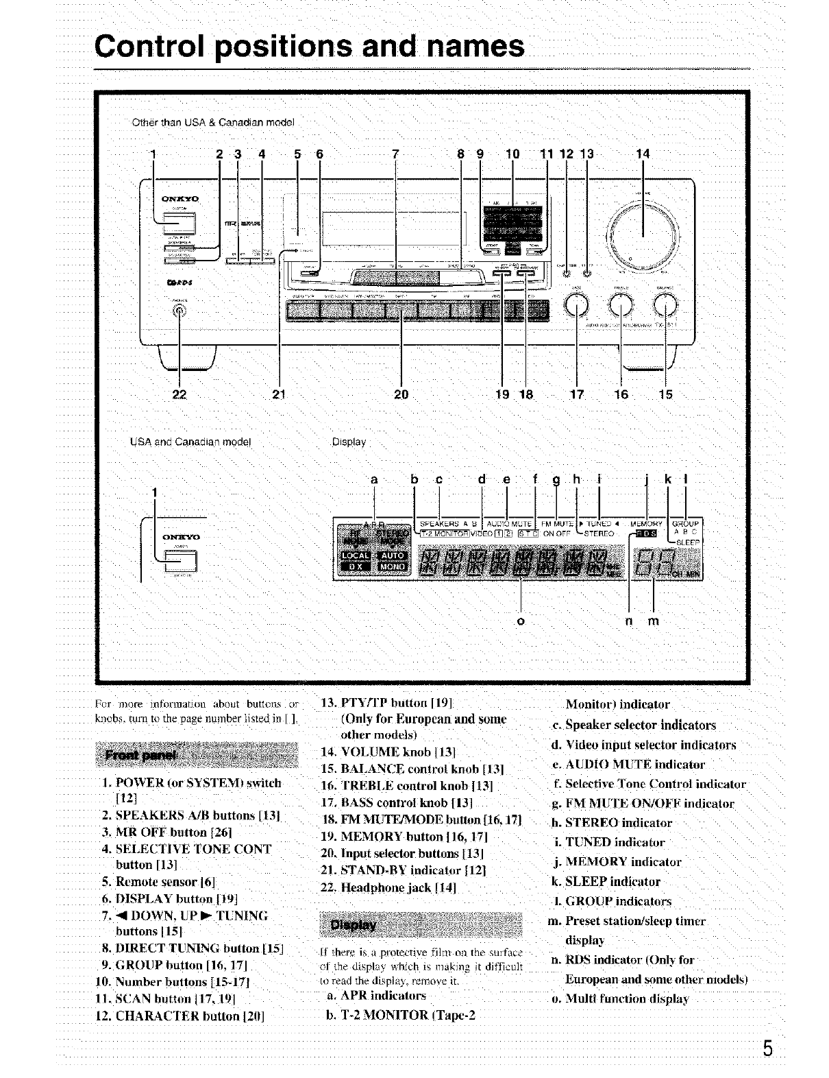
FiJr mure nltwii1alJon abollt btulotlS or
knob_, turn to the page number listed in ],
1. POWER ,or SYSTEM_ switch
HZ]
2. SPEAKFRS A/B buttnns [13J
3. MR OFF button [26]
4, SELECTIVE TONE CONT
button [13]
5. Remote sensor 16
6, DISPLAY button 119J
7, 4 DOWN. UP I_ TUNING
buttons 15]
8. DIRECT TUNING button [15]
9. GROUP button [16. 171
10. Number buttons [15-17T
IL SCAN button 117 191
12. CHARACTER button [2il]
13, PTY[TP button 119 Moniturl indicator
(Only for European and some c. Speaker selector indicators
other models
14. VOLUblE knob 1131 d. Video input selector indicators
15. BALANCE control knob [131 e. AUDIO MUTE indicatm'
1: Selective Tone Control indicator
16. TREBI,E control knob 1131
1% BASS control knob [13]
18. FM MIJTE/MODE buttun [t6, 171
19. MEMORY button ]16, 171
20. Input selector buttons |t31
21. STAND-BY indicator [12]
22. Headphone jack [14]
[f there is ;/ protective fl]IlI oil tho surface
of the display which t_ making 1[ diffiuuh
m reao the d _pla}, remove i_,
a. APR indicators
b, T-2 MONITOR ITape-2
R. FM MUTE ON/OFF indicator
h, STEREO indicator
i. TUNED indicator
j. MEMORY indicator
k. SLEEP indicator
1. GROUP indicatnrs
at. Preset station]sle,:p timer
display
n. RDS indicator (Only for
European and some other modelsl
u. Multi funcBon displa3
5
Control positions and names
1. POWER --
2. INPUT-
S ELECTOR
DECK-B
4. TUNER--
5. CD
ni i ilia n
6. SLEEP
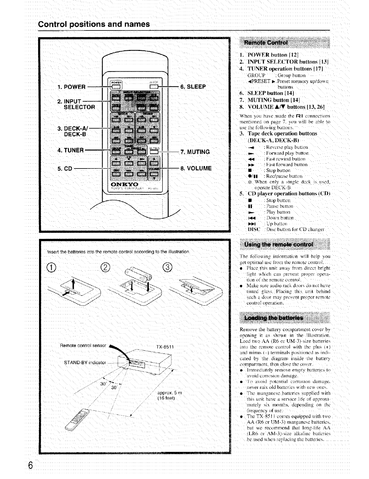
1. POWER button 1121
2. INPUT SELECTOR buttons 13]
4. TUNER opt, ration buttons [17 I
GROUP Grpup Dutr(m
4PRESET b.Pre_et memor_ uFaowl:
[_Ll/lOIIh
6. NLEEP button [14]
7. MUTING button [14]
8. VOLUMEAIT buttons[13,261
_¢VheII_(RI ha'_e lll:lde Ihe RI c()]tll_Clloil_
mcnnone(1 m pa_e 7, ytm will be ,.hie to
use the folht_xi]ig )utton.
3. Tape deck operation buttons
DEI2K-A. DECK-B)
-_m : Re_el_e pla} button
:l_tM rcwli/d [311ttOl
IM_ : ]-a_t fol%vard I_HI_OI_
•:Stop butlon
OJll - Rec t_ause humm
Whell mH a single leek is u_ed
operate DECK-B
5. CD pla_ er Oln'ralion buttons tUD_
• : Stop burthen
|1 . Pause hutttm
_.- "Pia button
: DO_I/b/llton
I1"11_1 : L P DUI{OI
I)IS(" _)i_c button lol ('D changer
Insert the batteries into the remote Contro] according to me illustratlor
@ @ @
Remote control sensor ___. _ f----'_. TX_85i1
STAND-BY indicator F--W /
30" "_0" _
_DDFOX. 5 rr
I6Ieet_
c_
The fl_lk),_ing inlormalitm will hem _,,u
_et _13til_lal u_,c llXll/] the rt'lllot£ _ uon[io]
•Place thi_ unit awa} _rom diwct bright
hght which can prevent proper ope_a-
[iOll o} 111_2i-Clll{)[_ c'tliltr(
•Make %irk2 audio rack dt_lP, do llot have
illl/ecl _la_ {Placlnfi thiq u1111 DeI/IIICl
_Ltch _t door rrltl,_ prcw'II! propttr r_,_I3(_ft.'
control i pr'ra_lon
RcnlOVe the batter), cuulpartment cover by
Op_l'_ing It £_; _111IWI? In the lllus{ratlltn.
Load two AA R6 or UM-3 _ize banenes
inti [llt_ Felllute CO{liFo] V_III1 tilt' pllk,
rind Illi]ltl_ lelTlqilla]5 r J_4lll£)llcd llS llllJ]
_;tted Dy me alagram tnslde Ihe Ilii/IeQ
COnlpar[rllcRL [nen cloxe [tie COVet
•lllllIle(1Klfely ]elllt)Ve t_IILp{) 'JKII_2IIC. _,
l_,lHd JoITOMI)n tl In]il_
• il_Oltl _OldnHa COIT(IMtlB tJkl/lla_g.
ne_,el nlix old batteries with nc_* vuc_
The" [lZlil_alleSC Da[lt_rlt% _,upplled with
/hl_ UlliI have a sL'r_lc_ ]i_ el ;lpproxl-
mateiy si_ momhs, depending on the
II_quency _| use
•The TX 851 / celtics eoumr_ed with two
AA _R6 or UM-3} manganese batteries.
hit v,e rec_nnmend that long-life AA
I.R{_ Ir AM 3 .,.= aIkahll{ D2{I[_'I-1O_,
be Llsed _ hen replacing me DaEerles
6
Making system connections
.J
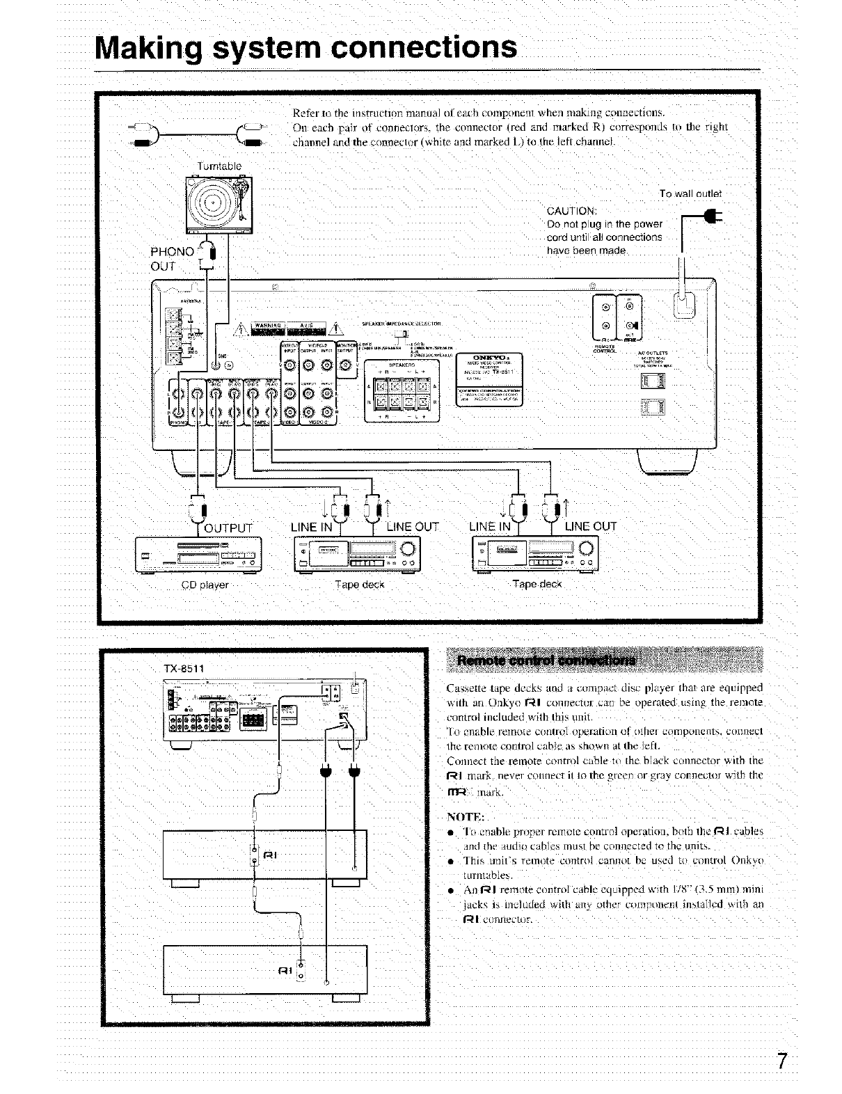
Refc " o the instrtm ma lit mum o! el/oh co ?lponenl when making Collnec[lons.
Oi1 each pair el conlleclor_, the connector Ired and marked R cor[es[_tnds to the right
channel and the c(llalle_2ttlr wrl_ie and marked L/to trle lei[ cnamlel
Turntable
PHONe _
OUT
7
jt
m
To Wall OUEle[
CAUTION
Do not pug n the Bower
cora anti all connections
tl,'3v_ oeerl maoe
T
_rehN^
m,lg qUIRN%pi
_ vlez,3z
LINEINT -[ LINE_UT
CD [3aver TaDO OOCK
_e_otE
ou_r_o_ A_ OOT_TS
LINE _N? ? ILINE OUT
Taoe QeCK
/
TX-8511
t
[ll[r_ll i -
Cassette tape ucc_s an_ acur'ilp;/c{ disc player that are equipped
with an Onkyo I'll connector c,1}? pe ope_a/eo u_lng tile remote
control included with Ih]s unit
_1o enable I'_'lllOfe CtltllrOl opera[llt[l 01 O{[lg! {20r ponerlp,, C£_l]llgCl
the remote control cabJe as shown at the leH,
Connect the remote t,,ntrol cable tt {he black connector with the
1-41 mark never COIlllPC111 IO the .areen or gray ctmnector with the
mark
NOTE:
• I'o enable ploper renlole control operauon, both the I_1 cables
Jnd die alldlo cables must be connected to the units.
• This tltl{/'5 lelllOte COrltrO] caIll]O[ hi2 U_,Cul _{] u_In[rt}l {)l]k\'o
iurntables.
• An RI remote control cable eqmpped with I/8" (3.5 ram/mini
acks 1_ l]lt21uOed wllh all_ other corer lit-fit in_lallcd with ar
| cl]l]l]ector
Making system connections
I
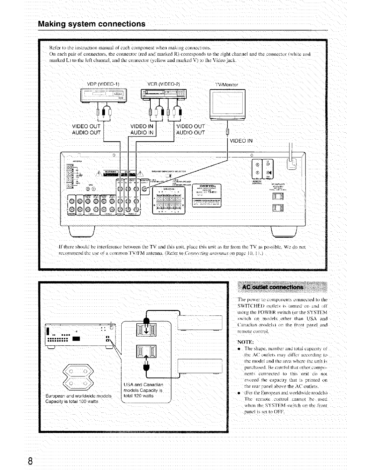
_ct_f to [hi =IlIF,[FtICtlon llltIIlu_ll Of _2flc_] Ci)II'ipII[Ittlll _,nel] 17lglkli]_ CI'HIIIt_t'tlDH_.
()n eflt'h pRir of conl1_CIoI_ [ne COlln_c[ol r_| al3d fnaFked R coriespollds to the/l_b[ chtti_ile] f111€2the _2Onll_C[t)l- While ii}ii!
InaJked LI to Ihc left channel, and the cunncctoJ (_ :llow and maJkcd V" to the Vidc;_ ack.
VDP IVIDE©-I VCR (VIDEO 21 TV/Monltc
',_J L__J
[f there should b_: inlvrlerence between the TV and thl_; tnm place this unit as Eu from the TV a_ possible. We do Not
....................................................... 117_ff
EUTODe£trlana worlawlae moaels
Cavacitv is total 100 watts
USA and Canadiar
models GaDacRv _s
total !20 watts
TIll _ Dtlwt-p it) C[)ll/[)£_lildllI3 _2DIII]('L{t'LI 10 [[Lt'
£WITCIIEL imllels is turned on and _II
usnlg the POWER _wltcn eI the SYSTEM
_',_llch on models _ther than USA arid
_hlll_idl_lII IllOLk'_ 11 tile IrOllt panel 0lid
No-rE:
I1_ Th_ },}IBD_? IILLlllDCF R/ILl [OL_lt t'Llt]Ltt'lI _ OF
Ihv A(' lllit}pl_ i11;1_: dii]#r aceordiI_ E II
lhc model ;rod the arva _ hen- lhe unit i,
purvha,,vd B_- c;irt'tld th;t[ Oll r c/lmpt_-
i!¢!11 _ _'Oltllecled to Ibis tlrli{ .rlDt
me _ear _anel above the AC outlets
• i'o_ the lain pean :rod woHdwide mode]s
ilit- Ii'lllO[_ Ct)[lIl_OI C_lllEOt b_ [l'_[
wn{'n me SYSTEM sw tch on lhe frollf
pan_q ;s _et to OFF
Making system connections
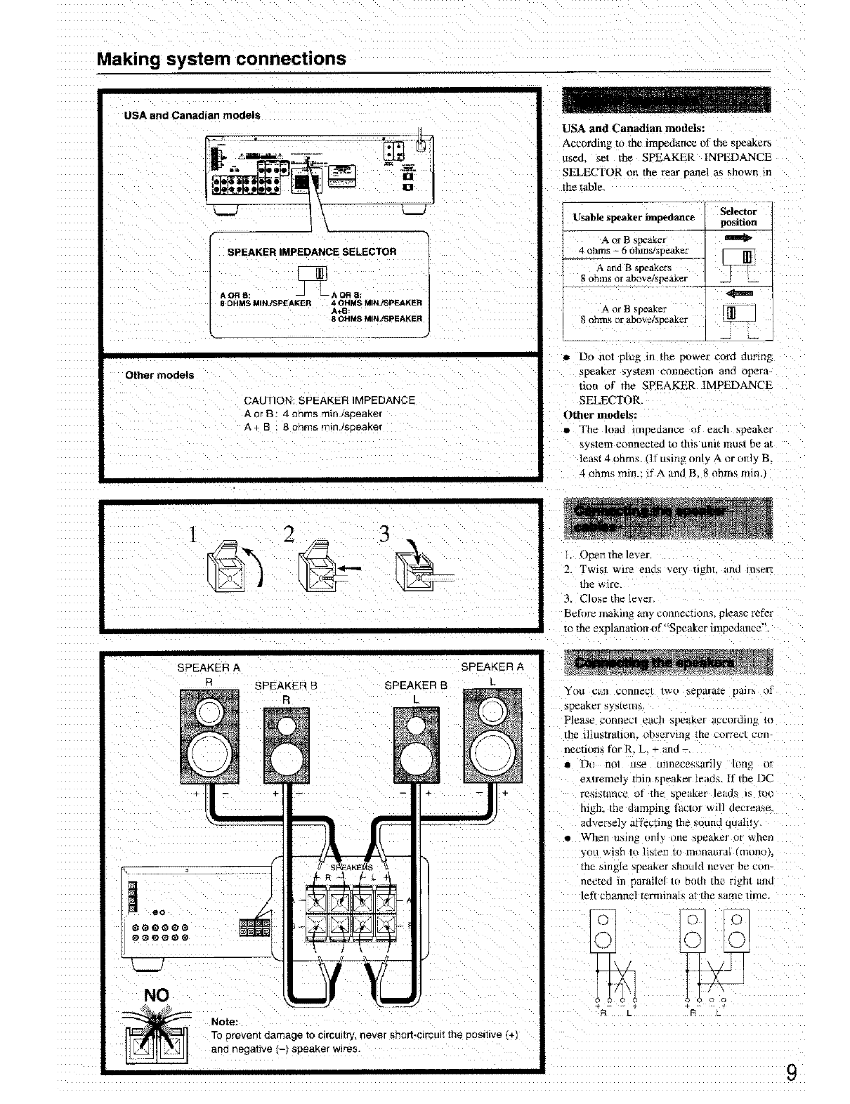
USA and Canadian models
"!
SPEAKERIMPEDANCESELECTOR
AORB: _AORB:
g OHMS MIN.PSPIEAKER 4 OHMS MINJ_PEAKER
A+B
8 OHMS MINJSpEAKER
Other models
CAUTION: SPEAKER IMPEDANCE
Aor B : 4 ohms rain/speaKer
A + B 8 ohms flqllq./sD_aKer
USA and Canadian models:
According to the impedance of the _peakers
used. set the SPEAKER INPEDANCE
SELECTOR on the rear panel as shown m
the table
Usable speaker impedance
A or B spea_er
4 ohms - {_ohms/speaker
A and B _peakers
8 ohms or above _peaKer
Selector
position
A or B speaker
8 ohm_ or aNdre/speaker
• Do not plug m the power eora dunrlg
_peaKer _y_lem col_necttflll and opera-
tion of the SPEAKER IMPEDANCE
SELECTOR.
Other models:
• q_le load mlpeaance of each sl_aker
system connected to this unit ll/osl be at
least 4 ohms. ill u_ing onl) A or only B,
4 ohms rain.: ifA a_d B, 8 ohm_ min._
2 3
SPEAKER A SPEAKER A
SPEAKER BSPEAKER B L
R/
%
L_.J
NO
Note:
TOprevent _3amageto circuitry, never short-circuit the positive (+
and negative (-) speaker wires.
l, Open the lever.
2Twist rare ends very tight, and insert
tile _,_/rc.
3 Close thelever
Before making an? connecuons, please refer
m the explanation of"Speaker impedance".
You C_II collnecl _WO he_alrate pairs of
speaker _ysteme
Please conllecl _ach speaker accorth/l_ ]o
the illustration, observing me correct _2(iii-
nections for R, L ÷ tmu
• DI IlOl LIq_' klnl/l?Cehgllrily hmp nr
extremely thin speaker lead£ II the DC
resistance of the speaker leads is too
high, the damping lactor wall decrease,
adversely arrecnng the sound quaht_
• When using unl} one speaker ur _hen
you _ish ta listen to m_maurai "nnn_ r.
the single streaker shlttlhl lleVer be con-
netted iI parallel tu D(Illl the right aria
left channel wrminals at the same time.
o
t_ c_
9
Connecting antennas
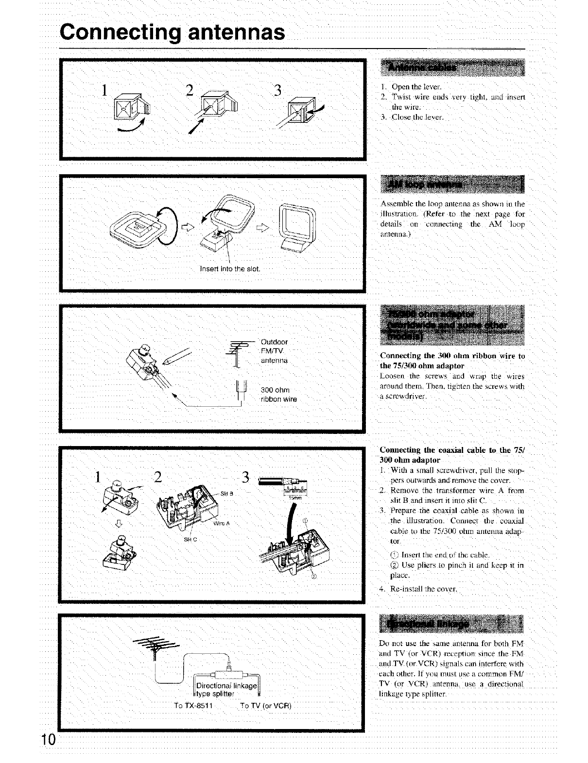
31 Open the lever.
2, T_,Ms[ wire _llds _ery IlghL _lntl in';erl
the wire.
3 Close the lever
v <_."..i2r
Insert into the slot.
_ , Assemble the loop antenna as sho_ n m the
i[lu_tratlon IRefer t{/ the ne×l _a_e for
detall_ on comlectmg the AM lo_p
atilenna.
.__ Outdoor
-- 300 ohrr
rlooorl wire
Connecting the 3JR! ohm ribbon wire to
the 75f300 ohm adaptor
Loosen the screws and wrap me wires
around them. Then. n_hten Ihe screw_ wlth
fi _crewc]ri vet
Connecting the coaxial cable to the 75/
300 ohm adaptor
I. With a small scl_d_-ivel, pull the stop-
pers outw_trds and rem_ve the cover.
2 Remove the trall_forlner wire A_rom
sht 13 arid in_ert Jt into sht C
3, Prepare the coaxial cable as _hown in
the illustration. Ctm]_ec! tile COtL_ial
cable to the 75131X) uhm amenna adap
tor
ln,_erl the e_d of the cable
2) Use pliers to pinch _t and keev _t in
place
4, Re-install the coxe_
To TX-8511 -o TV rot VCR
Do n_!t use the _ame antenna for both FM
and TV ar VCRt r_ception _ince the FM
and TV (_r VCR) signals can interfere with
each l_ther. If y_t] Intlh[ tl_c aCOlTlmon FM]
TV (or V('R) antenna, use a directmnal
mkage t_pe spliuer
Connecting antennas
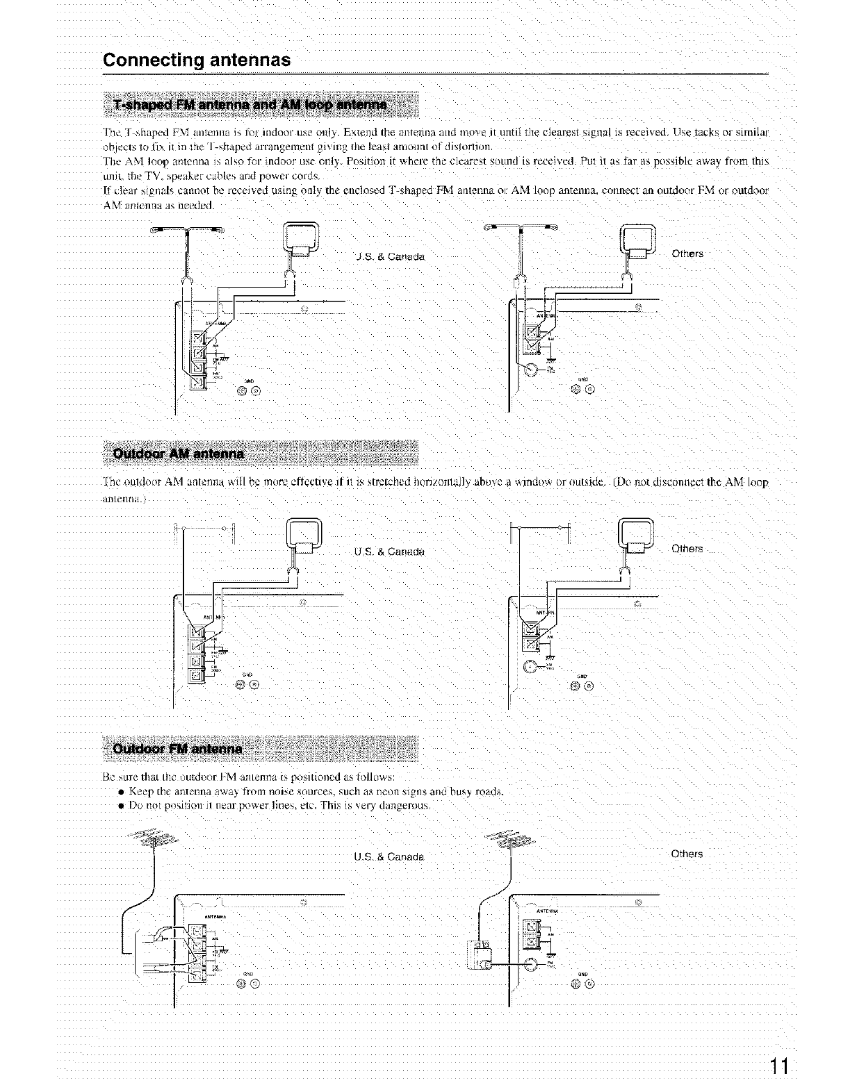
The T _hat_a FM dll[_'lllI_l ]b 1_ illdOOl" us__ OlI]\. Extend file _n[etllla _lld tllove i[ IlII[il rile clearest signal is received Use tacks or smlilar
,r _Is t{i I/x iI iii ll/_ 1-*,[i__cl] aTra[l_el/l_lll _OlVlli_ [Fie leaM il[llOlll/t o_dis[OrIlOn
Tht- AM loop amwnna is mso fur indoor use onl) Position it _vhere the dearest sound is received. Put it as l_tr as possible awa_ irom tins
ullit, the TV. alleaker canes alId power corl{q.
If clear - gnal¢ calItlot be received usln_ only the enclosed T-shaped FIvi antenna o1 AM loop antenlm connect aa outdocn FM or out&_or
AM antcnrla as m't_lud.
®®
J S & Canada Others
I lie oold(_(!r A.M a/lletir/a will be l_]ore _t_dCIIVe II ItlS _lrc/ched horl/(lrllltJ] abo\e a tallldl}_ ()l" t)tltMd_
;llt [L'llII il.
o
Lr_J US & Canada
Do not d_sconltec/the AM loop
Be sule thai th¢, uutd_tlr IM an/eltna Is ,)OSl[lOIled a5 hllhiw_
• K_e r [he al_tel_13a awa) flotII t'_ise ,;(l[ir_ ?_. C,llch as i/_otl M_n2, alld bus_ _oi_ds.
• Do 11o[ pl/MIion 11 ileal ¸ power Iltle_, _lc. Thb, Is _,_Q,_ uan_erott:_
:Z._2.--
US & Canada Others
J
11
Connecting the power
• Beh_rc plugging t11the umt. conlirm that all conneclions have beeli made properl 3
• Be_rc turning on the power, be sure Ihat the VOLUME knob _ I_1/_ turned cou_terclockwtse.
• I Llllnng oil thl_ 11111[• power may can,c ;i n_)lnenlar_ power • lr_c. which nli_ht interfere with othel- eleclrical _qulpnl_llt. _,tl_ll _ c_lm
ptl[el'h. If SO. iSe tl wail OUl]el _ll_tl dilfer_'nl circLul.
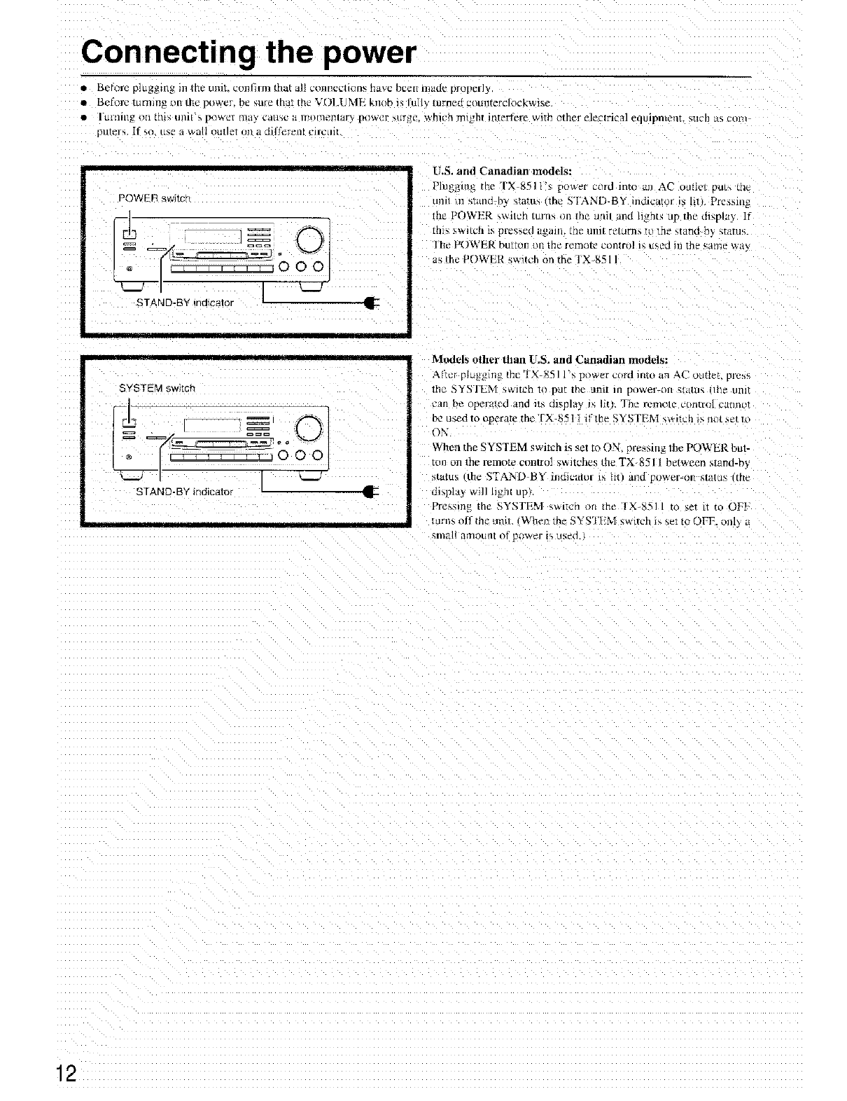
POWER sw_tcn
%A'B ,n o ,OE Ji-
tl-
i_llr i_n
SYSTEM switct-
dI-
STAND-BY indicator
U.S. and Canadian models:
PJugging the TX 851 i's puwer cord mm tm AC ounm put. me
_mn tn smnc] Dy _[altln the STAND-BY inolcalor is till Pressin_
the POWER _wncn turn_ /m mr. _IPl nnd hghts up the dl_pla_ If
[fll_ S._lt_rl is pre%e¢] il_allL rile 11111[rctLirn_ to _1_ _,tttlld h_ _,talub.
'I h_ POWLR btltLOli L)_ th_ f_lllOte coll[rol p, ilsed 111tile _;allle W_l_:
as the POWER switch on the I X_511
Models other than U,S. and Canadian models:
Aftcl plagging the TX _511 '_ pt_we_ cold into an AC oudm ptv>s
the _YSI'EM _ltt'h to [)tK 111¢tlntl Ill power-on Mdtllq tile /inl[
Call De opclated and i_n dlbpla) s 11[t. The FL'IT_I_)Iccontrol c£1ntll)t
be used to operate the TX-8511 it"the SYSTEM swift h is m_t net tl
ON
When the SYSTEM switch is set m ON pressing the POWER but-
tun on the mmo_e control sw_tO_es the TX8511 between sTand-by
_tatus tthc SIAND BY indicator _s hi) and power-on slatus trle
dbplay wi]] hght up}.
Pressing me SYSTEM switch m the 'IX 8511 to set tl to OF}
turns off the an Wben the SYSTEM sw_tch is set to OFF. onl\ ,_
£nlall arll_)U/llo[ power i_ used.
12
Basic operations
2
]==
5
1
oo0:,
56
4
5
6
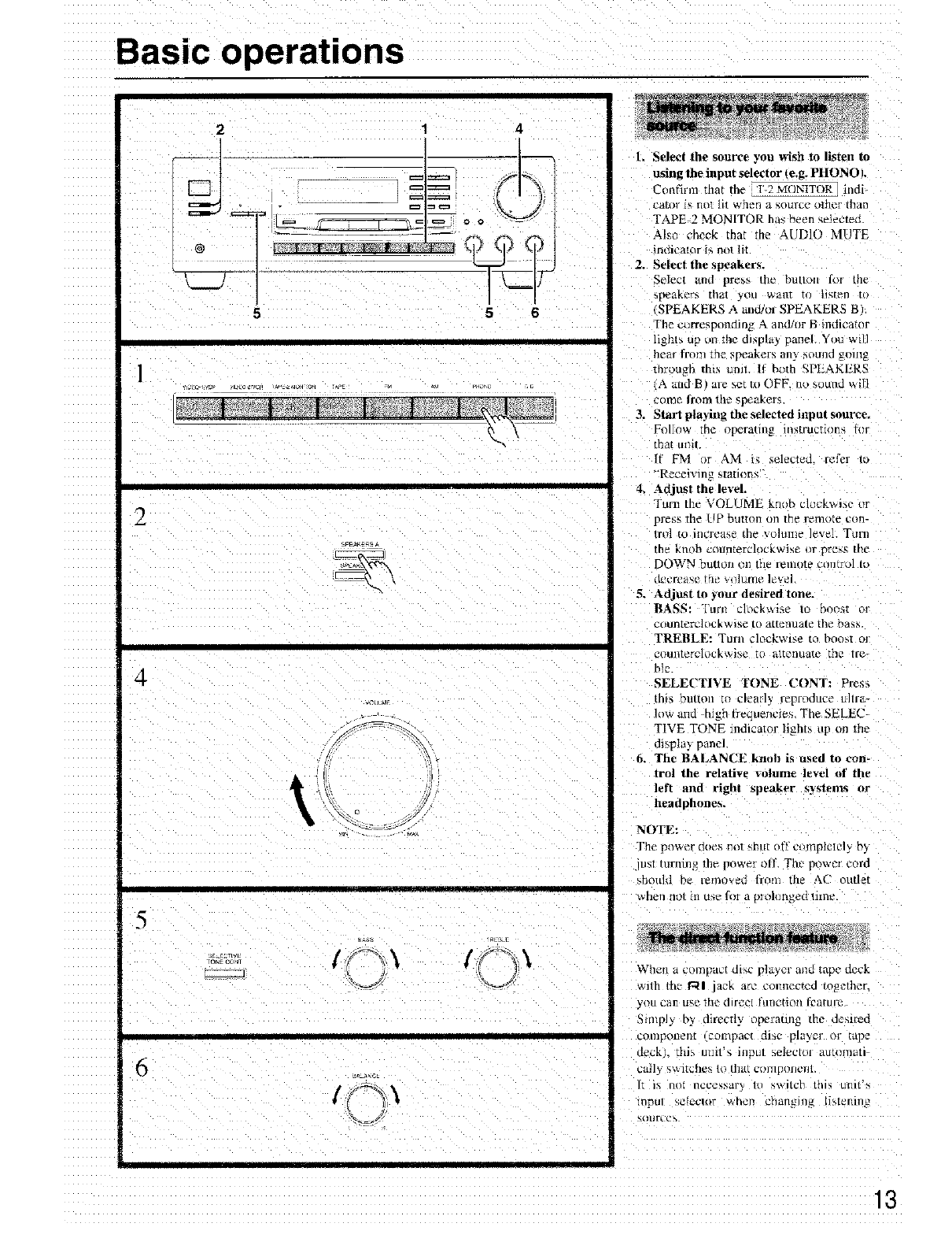
l. Select the source you wish to listen to
using the input selector 4e.g. PHONOI.
Confirm that tile F_MONtTOR] indi-
cator i_ not lit V, ilerl a _,OtlrCl" ub]eF tllarl
TAPE 2 MONITOR has been selecte_.
Al_t_ cheek that the AUDIO MUTE
indicator is not lit
2, Select the speakers,
Selecl and pre_ the button lot the
_pl_fikGrs th[4.t you wk411I iI%[_n i
SPEAKERS A and/ul SPEAKERS B
The c_lrre_pondhl_ A and/llr g indicalor
llght_ up tm tile dlspla_ panel Yt>u will
hear from the speakers any sound going
mrouffh tl_._ umt. I1 Broth SPEAKERS
{A aud B a_e set Iu OFF. m, sound will
come from the _peakers
3. Start playiug the selected input source.
Follow [he opera[/ll_ InstrUCtlOl't_ tilt
that umt.
If FM )r AM i_ selected, refer 1o
_'Recei_ing statmn*'"
4. Adjust tile level.
Turn the VOLUME knob cl_ckwiac nr
press tile UP button m the remote con-
Irol to increase the x{_lulll_ level. Turn
the knob counterclockwise or Dri2ys HlC
DOWN button _.}III}le remote c{mtrol t_
Ol%'g_ 4he [rlt _ _t3_l rllu leve
5. Adjust to your desired ton_.
BASS: Turn clock_ise [o r_oos:
counterclockwis¢ to attenuate the bass
TREBLE: Tmn clockwise to boost o_
¢ount_,r_-lockt_,l_,e to att_-iiixate tile _re-
No.
SELECTIVE TONE CONT: Press
this bulton tu clearh' reproduce tlllla-
low and high lrequencies. The SELE('_
TIVE TONE indicator lights up on me
dtspla_ panel.
6, The BALANCE knob is used _o con-
trol the relative _olume level o[ the
left and righl speaker systems or
headphones,
NOTE:
The i)nwer _oe_ m_Tsnul oil c_/mplctely b_
iust turnin_ th_ power _ll'. Th_ pt'_wez"cord
_holtM be remm, ed from tbe AC outlet
when IlOl ili tD,_ for LI proh3n_LI lnlle.
When a ct3fl3t3_tcttllsc player and tape deck
with _he r_l lack art. eomiccted rogetber.
y _tt can u',t: lhe dlrgeI lung(toil lh'attll'_
5mlply by dlrect_. _peraung the desired
colnpollen[ icola/pact disc plaver or tape
deck/, tlll_ I111t1 _ lflpU/ l_elec(l_l aut_l_/l_ii
call 3, ",_ ltche_, to that C_nlpo[icl]l
IL 1_ DOI ilt2c_2ssl;ir_ 10 _,w1[/213 trip; UlOlt',%
lnpul Y,i21_Cl_r when chan}J /g LJ_,l_lr/in_
Basic operations
III
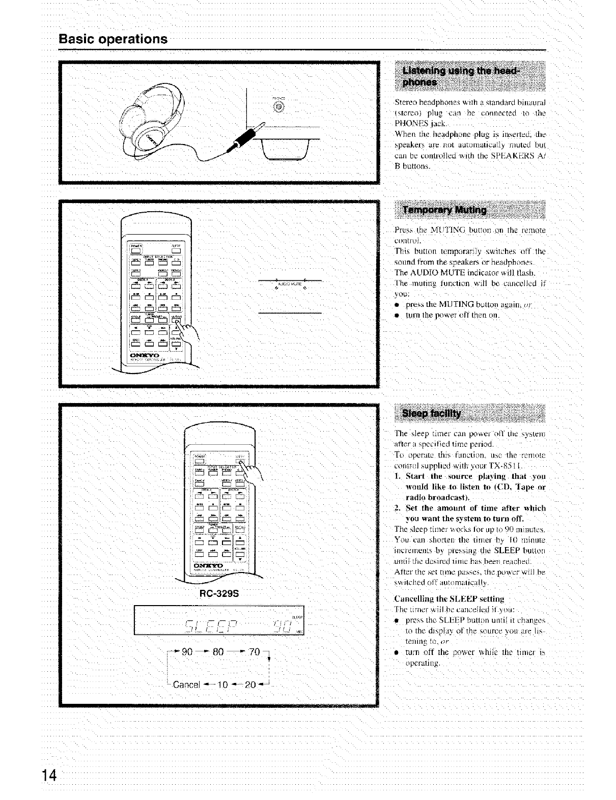
RC-329S
_-90_80_70
CanceJ * - 10 --20
_11 [
St_l'eo headphone_ wtlh a s/ai)dard bnlaura
_r_o p]tl_ c311 D_ cOflllL'c_{Itl 1o filL"
PHONES _ack
When the headph_mc plug _ u.serted, tile
q3_aKers are R/K dLl[ill/l_[II_a 1lnUlt2(} [)U[
:an Be ctmtlol]¢d with th_ SPEAKEP.S A
B button_
Press the Mt TIN( ;button on the remote
_t)ii[rol.
fh ¸ D/IHOn teiilpt)rarllV 5,WltCheg ti 11_2
sound from Ihe speakers or headphonea
The AUDIO MUTE indicator _ill flash
The muling lunctwn will be c_mcclled il
)ou;
pre_s the MUTING button again, u_
• ItllTl Hie power I)If Ul_rl or
The sleep [lI_ler call pOWL'r ofl tilt' s}Steln
_tT[e] _ a sp_t'ltted !lille p_l'lOo
Tt) operate thtt4 fllnction /ibe [ne elnu[P
con!m/*upphcd wile your TX-8511
1. Start the source playing that you
l_,ouid like to liMen to ICD. ]ap_ or
radio hroadca_| ,.
2. Set the amount of time after which
you want the system to turn off.
Tile sleep tlllleF tA orks Ior i pio "]U mllllll_ "_,
YOU cat! shorten tile [l_]l_l r_ t_) rll/ntlle
h/elements b) prc,_mg the SLEEP bunor
Ul]ti] tile dcsh'cd lilnc ha_ he.ll let!the.,.
Aller th_ set [im_2 i)tt_p.c% lllC pOW_l Wit] be
_,_.IICIleO OI 1 al.l[tllllall('a
('unveiling the SLEEP setting
The unwr aitl b_' can:'eIled it *u
• pre_, thP SLELP bu/tc_ll untd it thai _e_
[o rnt" ol_ldy o/th_ _.ourc_ yell ttld h_
[ellln_ to. i)r
II tllrn olt tUG [_,OWt:[ Willie Illt" llng:r 1",
o_ranng.
14
Receiving stations
= ©
Vq ====
=2=a:22_2_ •
+ 000
21
/_//' t,r
2
,_+'_J•, J.LL_.L.• _eCJ ]
- L I_ I I_1--
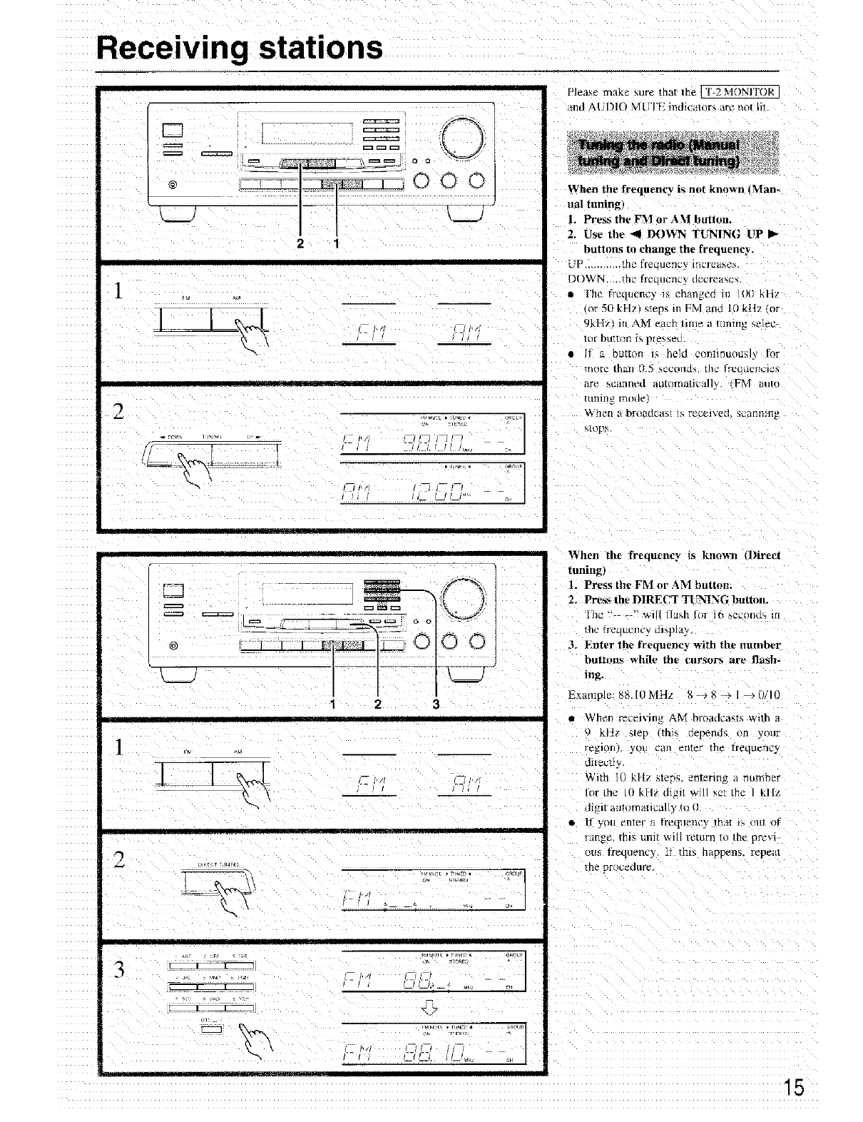
Please make sure that the [T 2 MONITOR ]
and ALl)In MU IV indicalurs arc nul fil
When the frequency is not known _Man-
ual tuning)
/. Press the FM or AM button•
2. Use the 4DOWN TUNING UP
buttons to change the frequency.
UP ............ the frec ll.nl'} LtlL'IC4_,O>,
DOWN ._he Ireu,Jenc_ necrea_c_
• The fl'eqacncy is ehangcc: :n loll kH/
or 50 kHT/sleds in FM anti 10 kl]7 or
9kH¢ ill AM each time a tLlIll[Ig .elec_
toI huttorI 1_ piesse_.
•If a bu_ton is held cont:nuou_, or
more than [}.gseCOlld_ [hc lrl2[_klCIlCld_,
are _canned automallcM/v (FM auto
[llTn]l_ I't/I }/le
Wh_tl a broadtail 1h receD.ed. Scgtnltlll b
_tops
1
2
I I[ll
L__3 k__.
1 2 3
tt_•a : rF_
_ ,, T,, Tear • _RC_
t--
I I I[
When the frequent3 is knnw_ Direct
tuning)
1. Press the FM or AM button,
2. Press th_ DIRECT TUNING buttolL
[]/c .... will lla:.h Io[ l(_ _,ccon_:_ m
um trequcnQ mspla)
3, Enter the IYetluenc_ -_ith the number
hutt_m_ while |he t'nr_()rs are Jmash-
Example: bb. IOMHL _ _ _ -- l-+(.VlO
• When I'ecci_m_ #.M broadcasts with a
9kH] _tep mrs depends on y:n:r
re_!lonlyLluCalleillerthe l='eqLlerlcy
d:_ct :
With IO kl[i steps, emenng a numr_er
lor _he tO ktlz digit will set the 1 kllz
tlH2i[ a:ltonlal:ical ) [<_
• If vim enlt, r :J lYetluenc _ that _s ()ill or
_zmge, mis uni: will return to me prey:
uns irequenc 3 I] this happens, repem
the procedure,
Receiving stations
16
3
4
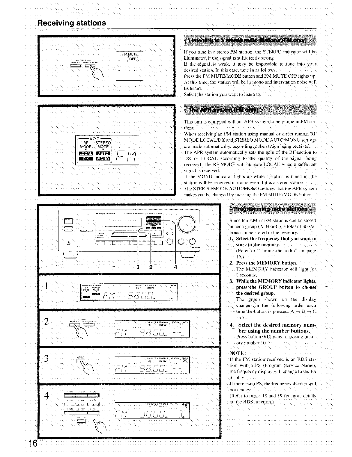
_MgUTE If you tune m a stereo FM statlor the STERE() indica/or _viil be
dlmninated if the m_na[ is sulflcmntt> strong
[f /t1#2_iga al is weak. it mu_, De impossible to tune tnr¢ your
desired _tation. In this case. tune m a_ lollows.
Press the FM M UTE/MODE button and FM MUTE OFF lignrs up.
At this rune. the stat_oJ_ will be in mono aad intersration no_se will
be heard
gelect the station you want to hs_en t_
=_" STEREO
MODE MODE
E]]_I 1-- P/I
IDlll ffa'_;'l I--1 I
This tlnll is eqmpped with an APR s_ stem to helg tune in FM sta
nons
Wh_'T1recmvmg an FM station using manual or d_rect tunllaI2 R[
MODE LOCAL/DX and STEREO MODE AUTO/MONO settings
ale nlaoe atttolllatlcally, according Tothe station being recei_ec
fbc APR s) stem autOmaDcall_ set_ the gain of the RF secti,m 1o
DX or LOCAL according tu the qualit3 ol the signal being
received. The RF MODE wilI indicate LOCAL when a sufficient
slgllal i_ received.
If the MON() mdicalor lights up while a statJun is tunea m. me
_ld[ItHl will be received in mono even if it is a 5;rel_'Osrarton
Fhe STEREO MODE AUTO&'IONO settings that the APR s_atem
makes can be changeo t)y plesslng the FM MUTF/MODE button
3 2
[
©©
k._..J
4
I[,/_
,l[
u_oE_rur_c_ ._ _7 "_
[ 1/
.u,_ *-uN_w
/I
[ .... I I
Since ten AM _,1I'M _,/atlona call be stol'cd
m em'n group _A. B or CL a total of 30 sta-
tions can be stored ill the memory.
L Select the frequency that you want to
sture in tht _memory.
,Rete_ tu 'Tumng the radiW" {_r page
151
2. Press the MEMORY button.
the MEMOR'_ mdi_tor _iI! light Io_
hecorlds.
3. While the MEMORY indicator lights_
press the GROI'P button to choose
the desired group.
The glou I 'd/l_wtl ill lbc di_)lay
Lqlal_?_ In [gll- _t/lJowii1}2 ird_l" cat.[-
tnne the button i_ '-re_ecI- A --> B-_ (
4, Select the desired memory num-
ber usin_ the number buttons,
P1¢'_,_, button I.)/lR _[itJt] cnil_>Mng ll/_Jn
_lV IlHtlaD_'F ]R
NOTE :
11 the FM statism le_eived _, an RDS sta-
tltln with a PS Plog[d/T1 _gvl_ Natu¢
the trequeney mspla', will change to d_e t'5
d_spla}
If there _s no PS. the frequency display wdl
I101 Cllange
Rclc_ Io pagc_ 18 and t9 fin mu_e de/a
m the RDS _ur_cthm,
Receiving stations
@
LA '__\ ===================_o o
kL_.I__L__ 0 0 0
%.,,
• %
%.
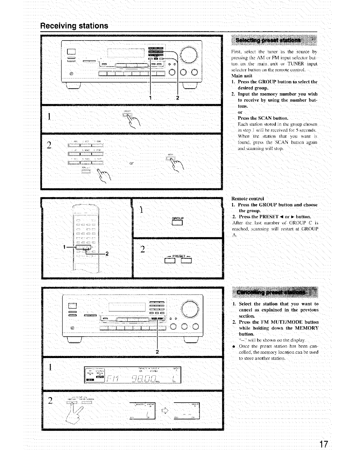
First _clcc[ the tuner _. thc gource by
pJwsing the \M or FM ir_ut sc]ectol but
tun on the mare unit uJ TUNER input
sel_ctiir billion t)ll the _elllOle c(Httrt_
Main unil
I. Pros the GROI JP bulton la sdeet the
desired tromp+
2. Input the memory number you wish
to receive by usinR the number but-
tons.
nr
Press the SCAN button.
Each _;tati(ll_ sR_red Jn the gl'<_tlpt;ll(_qell
m sle[" 1 win he r_ceived for 5 _ecand_.
_'bezl tile Sial]oil that y_u wan/ is
lounL Ilte_ the SCAN lutloIl aganl
+
'GROUP
_I_ lEE]
I_rJ
_c_ r_ _ I
2r 2_pRESET
r--1 r---q
t
-• tl
R_lllot _control
1+ Press the GROUP button and choose
[ the _roup.
2. Press the PRESET _1 or I_ button.
After the IaM i_ulnber oI (}R,)UP C 1_
r,,uched scannmu _ill re_tarl at GROUP
= ©
+_/ 0 0 0
I
2
2
1. Select the station that you want to
cancel as explained in the previous
seOion.
2. Press the FM MUTE/MODE button
_+hile htflding dox+n the MEMORY
button
• "' will bc shown on the display
•Once th_ pI'em_t s_a+ion has been can-
celled, the nsemor'- location can be used
[o _[OI'P anol3icr station
17
Receiving RDS (Only for European and some other models)
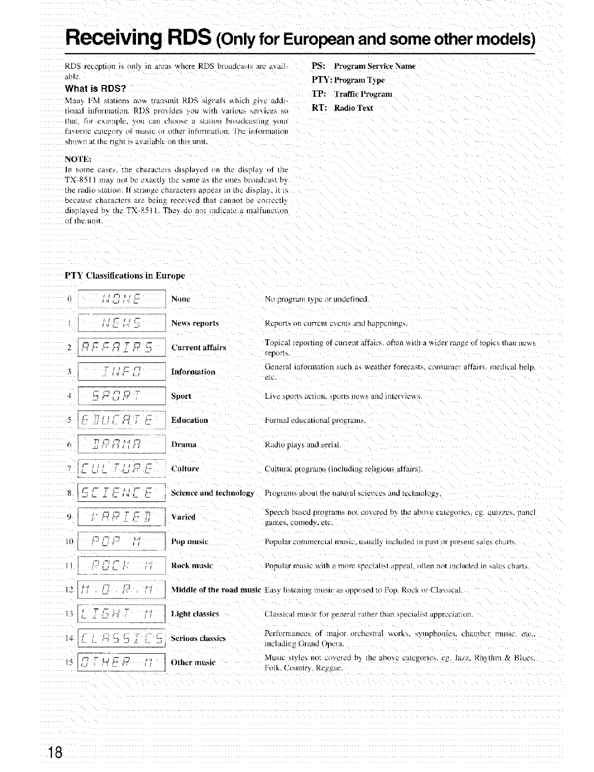
RDS reception is only in areas where RDS broadcayls arc a_ail-
abD
What is RDS?
Man! lz},'l _tatlotlx llO_ iranqinl[ RI),q ql,_l/al_ k_[Ih'[] _1%12 llddl
tional infornlation. RDS provides ?,ou _ith variou_ _ervlces _o
tll_ll _)I extlIIl|?]_, you Cil[I ('rlt_}_e ;t ,t_]dOll [_Io_ldc_/Slill_ Your
PS: Program Service Name
PTY: l'rogrmn Type
TP: Trall'ie Program
RT: Radio Text
[ilt{llllC Citl_2gOIy O[ nltlblC Ol olhcl" lIIJtH3TlaLIt)ll. [hL = II]{LIIIU}IIIOII
_h/Iwll at the ri_zht i_ available ilia this ung
NOTE:
In solne ca_¢_, trle chaz-at'tc_ dlsph_y_'d on the ch_pldy II ule
TN]-851 I ma_ not De _xac[l_ ll]e _al]]e _L_ in*" tltll'_, briladl>a_t h_
the radio statioJl. If stlang¢ characters a_ -_r m the d]spla3 l_ m
DC{alJ%e L'I]_IIaCI_FS _1"_ Dk2lll_2 Ik_oetv_d thk_t t, alll/O_ hp _'OIIt'_'t_),
a,spmyea l_y the TX-8511 The_ ao n< nmcme a malflnn'mm
_f the LiElI
PTY Classifications in Eur_pc
-"....... Z fl" -'_
NIIIII _ _1 program _ypc or ui_defined
News reports Reports oil CUITeIII t_veI1D, llno tlappclllng_.
Current affairs
Information
"_ _-- LA "-
Topical ieporting of cUilPllf dffail'b Ofh'll _,_,lth a wider l&n_e t/f klplcs lt1211I ilOW_
repol_ _,
at'llera[ irliOrillatlOU _tlC_l zt-; weather fOFeCa_K;, con_,kll]l,_r af[ail% tledlcal he]p
Sport Li_ >pot'r%.tC[ltHL ,i×}rm m.ws alld lrltor_it.w_
_I _ _] _ _f] _ ;- Education Ig_Ii'|n_] _?duCatlOllaI pl'O_l _lllt5.
Culture
i 5 '--g- i--}7 , , --- ,-_-'-- Sci_£',l,'e alai t_chllohlgy
_ \'aried
It-_ _ _ _ Pop music
l -' ..... ] R_t,k music
12
DrItlll3 Rt,dk phtys aad aerial
Cultural progtam_ (including Iellgious affairs)
PlklglKl[D. about the ilalulal sciences dlld I_Chilo]O_
_p_ech ba_cd p_)_ralll_ no_ co_ _red b_ Lh_ aho¥_ Ct_leL2(lrl_\. eg qltl)'_'c_, pane]
ga_llef,. 2ometly. _Ic
P_lu|ar corrllllelcla] fllu_ic, tl_lJtd[= inc]uded III |)_t_[ Ol pr_el/_ _a]es; C]IL_I_
[
P[_ular nltlhic _Aith t| rl/t_re speciahsl app.,. )lLetl noI ll](.lUkled in MJCh charts
MiddLe of the road music !Sasv [i_t_l_il/g t]_tt_tc tt_ opposed t_/Pop, Rock nr ('la_/ca
13 Light elt_sics
14 __ _ ,--_J3 2_ ± • -_ Seriousclassic,s
I_ --tic'- _ l,
Ig z_ _ _-_ t2- Other musk'
( [;issical ImJ_,]c h)l _t:]ler;i] ralher than speciali_l apprcc]mlorl.
Peri'OlTnancos )t llaalor olcheMlal work_ _ylnphollle3. ch_llilbt'I ItILLF.IU.etc..
including (}t_md Opel a.
MllslC style_ riot co,cited h)_ l!]c arlt)\,c C}lI¢2_Ol'lCS, t'g. J_i/_', _|1)thl_l & Bhle_.
Folk. Country. Reggae.
18
Receiving RDS (Only for European and some other models)
@
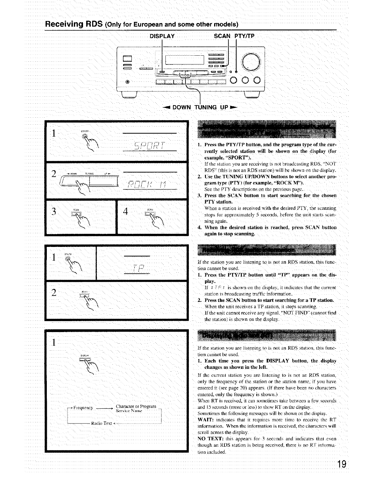
DISPLAY SCAN PTY/TP
o/,
-- 000
J
-.-,I DOWN TUNING UP
1. Press the PTY/FP button, and the program type _f the cur-
rently selected station will be shnwn on the display trier
example. "SPORT",,
[f the slalion you are receiving is llot broadcasting RDS "NOT
RDS" this is not an RDS statthr pwill be _hown on the display,
Z. Use the TUNING UP]DOWN buttons to select anuther pro-
gram type IIYFYt fur example, "'ROCK M_').
See the PTY descnpnons on me previous page.
3. Press the SCAN button to start searching fur the chosen
PTY station,
When a statmn is received with the desired PrY me scanning
_lops :_br approximately 5 seconds, before the Ill]It S[al4iSscan
nmg agmn.
4. W'hen the desired station is reached, press SCAN button
again to stop _anning.
if the station you are listening m ib not an RDS station, this lullC-
non c_nnol be used
1. Press the PTY/rP button until "TP'" appears on the dis-
play.
[t _-,c :is shown un the display, it indicates that the current
station is broadca,_ting traffic infi_rmation.
2. Press the SCAN button to start searching for a TP station
When the unit receives a TP station, i_ ,_tops ,,,canlllnj2
I1the unit cannot receive any signal. "NOT FIND" (cannot find
the station i_ shown on the display.
Dis_*
_ I-requencyRadio Text <
Character or Program
S_rVlC_ iNam_
If the _tation you are li,stening h} is no/an RDS slaHorL this tune-
non cannot be used
1. Each time you press the DISPLAY button, the display
changes as shown in the left.
[f the current station you are listening to is not an RDS station.
only the frequency of the station or the station name. if you have
entered ir _ee page 20) appears, lit there ha',e bee_ no charactera
entered, only the frequency is shown.1
_\qlen RT is/'cc_ivc_., it can sometime_ take between a t)w s_mds
aim 15 secund_ fmore or less lo show RT _n Ihe display
Sometimes 1he fr_llowing messages _il1 be shown on the display,
WAIT: mdieate_ that it reomres more nine to receive the RT
informatiom When the informanon is recmvcd, the characters will
scroll across the display.
NO TEXT: this appears foe 3 scct_iid_ astd indlcate_ that even
though an RDS stalacm is being recefved, there is no Rr miom/a
tioiI included
Entering station names
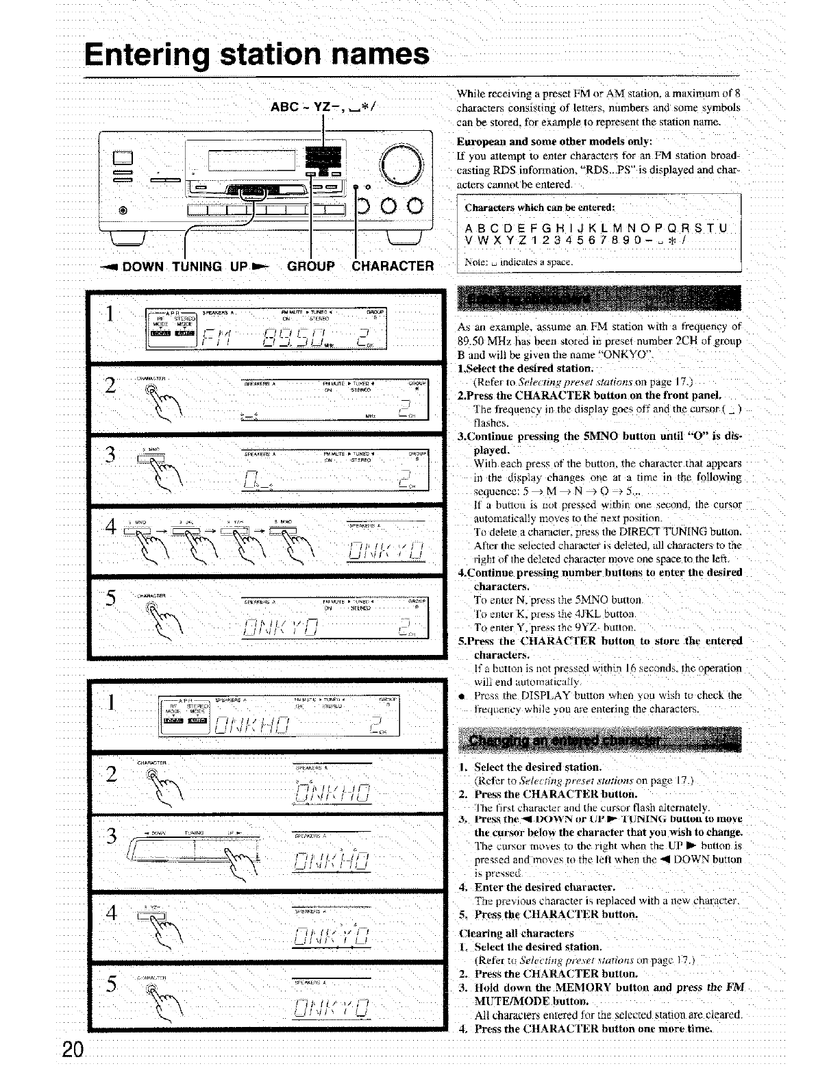
ABC ~ YZ-, _*/
®
DOWN TUNING UP =,"- GROUP CHARACTER
While receiving a preset FM or AM station, a m_J×imum of 8
characters consisting of letters, numbers and some symbols
can be stored, for example to represent the _tation name,
European and some other models only:
[f you attempt to enter character_ for an Fh/l station broad-
casting RDS information. "RDS.. PS" i_ displayed and char-
acters cannot be entered
Characters which can be entered:
ABCDEFGH]JKLMNOPQRSTU
VWXYZ1234567890-..
Note: u indicates a space.
........ 2/
r_m _,
3....................= _= f,.]
4 %
H
_I_ACTE
2
._r-a,
5 .......
As an example_ assume an FM stanon with a frequency of
89.50 MHz has been stored in preset number 2CH of group
B and will be g_ven the name "ONKYO",
LSeleet the desired station,
Refer Io Selectb_g 12re,_erstations on page 17
2.Press the CHARACTER button on the front panel.
The frequenc_ in the display" goes off and the cursor ( _ )
flashes
3.Continue pressing the 5MNO button until "O" is dis-
played.
Widl each pre_s _+fthe button, the character that appears
in the display change_ one at a nine in the following
sequence:5_M_N_O _5...
i1 a button 1_ Irot pl_2s_e_l within one second, lhe cursor
automatically moves to the ne_:t position
To delete a character, press the DIRECT TUNING button,
After the selected cbal_acter is deleted, all characters to the
right of the deleted character move one space m the left.
4.Continue pressing number buttons to enter the desired
characters,
To enter N, press me 5MNO bJJttOrl
l'o enter K, pJe_s the 4JKL button.
To enter Y, press Ibe 9YZ- bt]tto_,
5.Press the CHARACTER huthm m store the entered
characters.
If fi hHttOII lS tlOt l)ress_d wlthirl ] 0'q_ct)rld_,. the operation
will end automar]cany
•Press the DISPLAY button _hen 5ou wish to check the
Irequency while you are entering the characters.
I. Select the desired station,
Rei\-r to ,%letting pr¢_,t statton._ on page 17.)
2. Pre_s the CHARACTER button,
The [']r_t character and the cursor flash alternately.
B, Fre_sthe_l I)OWN orUP_ ItJNIN_ button to lnov_
the cursor below the character that you wish to change.
The cursor mo_es to me n_ht when the UP I_ button is
pressed and moves to the leti when the _1 DOWN button
i_ presse_
4. Enter the desired elmrac_er.
The prev=ous character 1_replaced with a new chmacter.
5. Press the CHAI_tCTER button.
Clearing all characters
LSelect the desired station
•Refer t+)Selectin_ m'(,_e_ wauon_ lln page ]7.
2. Press the CHARACTER button,
3. Ilold down the MEMORY button and press the F2VI
MUTE!MODE button.
All characters elltared for the selected station are cleared,
4. Press the CHARACTER button one more time.
Recording a source
2
@
__j
O00j
2
TX-8511
Recording] I r TI PlavuacK
Tace dec_ l Turntable
T_pE-1 TAPE2
CD player
I
VCR VDP
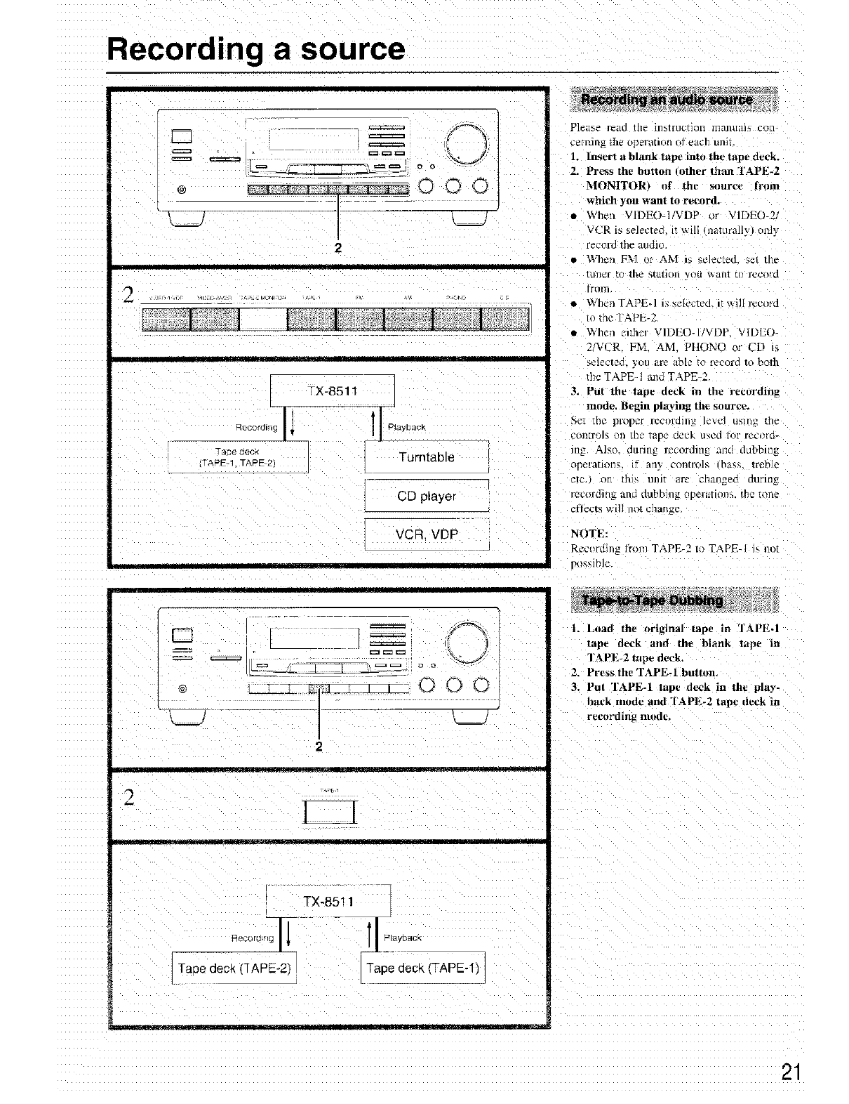
Please read the H18irlJcqoti /lialltla]5 c_Jil-
ceming the operation of each unit.
1. lrtsert a blank tape into the tape deck.
2. Press the button .other than TAPE-2
MONITt)RI of the source frnm
which you warn to record.
• When VIDEO-I/VDP or VIDEO-Z
VCR is selected it wdl naturall> omy
record the audio.
• When FM o_ AM i_ _e]ected se_ lne
tLllWFt(/ the _;[_[ion _;OLI_allt tO record
from
• \_h_'n TAPE-I is _elecled. it _i]l]ecol'd
to the "I'APE-2
• When cithm VIDEO-I '\:DP. VIDEII-
2!VCR, FM. AM. PIIONO or CD ,
SeleCtee }otl are able Io i_,c'ord to bc_th
the TAPE-! mad TAPE-2
3. Put the tape deck i_ the recording
mode. Begin playing the source.
.<A't1he pl'opcr rccorolllE lex_q LI'_tlI_[iiv
tpon[rols Oil the lape dock US_'LILot l'ec_llo_
lng Also. dm'ing recording and dubbing
rmeratltli_, if arly controls ha_,s treble
_[C, _ oI_ [I115 ll]ll_ _]'£' Ci1Etn_eQ dul_i[l_
lecordin; and dubhmg opcnmons, the tone
effects wil] not change
NOTE:
Rccordin_ m nl TAPE 2 to TAPE I i_,not
po_;_ihle
II = ol
F_ ====
__L__ ":=_ _, _,
I r T _'J_._L_L_L_ 0
II
2
TX'8511 _t
Taoodeo, mapo oo, /
-- _ -- _ .......... [r]l ......... [I
1. Load the original tape in TAPF-I
lap_ _eck and th_ blank lal}e m
I'A PE-2 tape deck,
2. Press the TAPEd breton.
3................... in the play-
hack mode and "IAPE-2 tape deck in
recording mode.
Recording a source
000
. _ |
2
II I
TX-8511
Recording Iv • IPlavoac_
VCA j VDP
!IDEO 2) V_DE©-_
[ J
3
D
o ]
_k__J
3 4
4
I
TX-8511
fJ- I I
vloeo V'dec Audio _ Audio
playback tecordfllg recording | playback
VCR (VIDEO-2) _'j CD player
Tape aecK
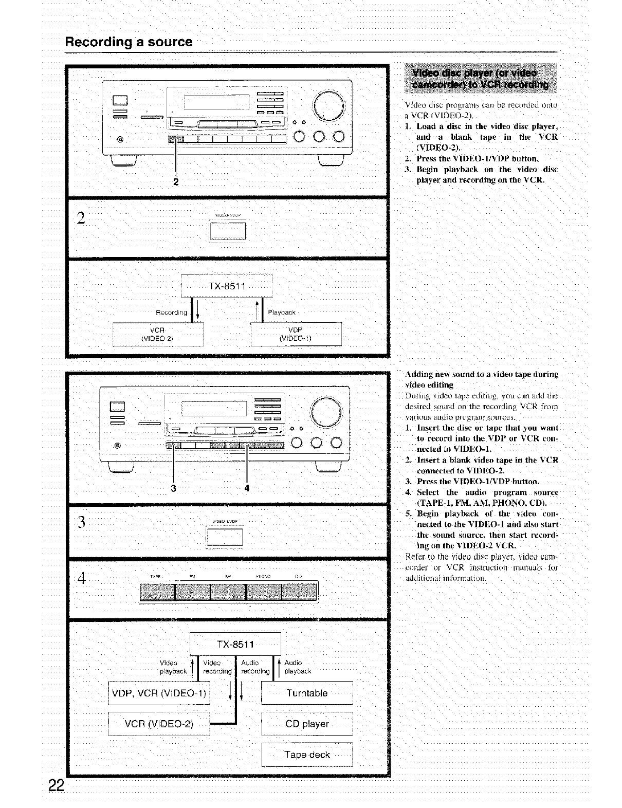
VId_o disc p[OEF_ffl_ C_fl D_ F_L'OFdCLIo[lto
aVCR/VIDE{5-2L
1. Load a disc in the video disc player,
and a blank tape in the VCR
(VIDEO-2).
2. Press the VIDEO- IiVDP button.
3, Begin playback on tht" video disc
player and recording on the VCR,
Adding ne_ sound to a video tape during
video editin_
During _idet_ lapc editing, y_t] can add th_
desired strand orl the recnrdin_ VL'R I?om
vari(l[1% alldio pl'o_r*l]]} s{ltlrcq_
1. Insert the disc or tape that you want
to record into the VDP or VCR con.
netted to VII)EO-I,
2. Insert a blank video tape in the VCR
connected to VIDEO-2,
3, Press the VIDEO-1/VDP button.
4. Select the, audio program sonrc{
¢TAPE-1. FM. AM, PHON(L CDL
5. Begin pla2back of the _ideo con-
nected to the VIDEO-1 and also start
the SOtlnd sotlrc_, tht_n start record-
ing on tht_VII)EO-2 VCR.
Reter to the video di>c p]a] :r video cam-
CIIFO¢'I _)g _r_" R ]13NITUUllI}11 ITI_411Ual_ lot
_tLIdltlt)Z}H 1 l[lI (IFEiH_lOlh
................ IIll[Ill[/[
22
Using TAPE-2 MONITOR
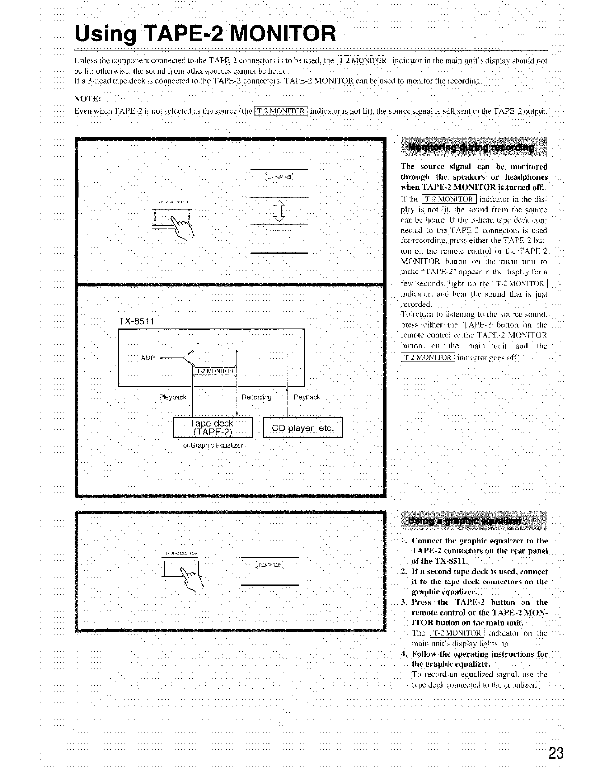
k [1Jess Ihe L'ompt)l]et]i _ tl_'lt]gc[_.] I_) Ih¢ TAPE-2 conneclors i_ to be u_ed. me _T=2 M_JNITOR lI_(JlL'[[[_)r t£ the m8lII tlnlt s dl_pla)' _hou]d nl_t
D{5111: o[h_rwl_e. [l_c So/[rid _ronl o[h_r _ource_; _RnRoI b_ h_0rd.
It a 3_head tape deck i_ connected to the TAPE-2 connectors, TAPE*2 MONITOR can be used to monitor the recording
NOTE:
E\ en when TAPE-2 i_ not selcclcd ns the suurce me IT-2 MONITOR ]indicator is no/hr . the source signal is still sent tu the I'APE-2 outnut
TX-8511
AMP '_l!l ,_TO_ ,
P ay[_acK Reco'ding
Tape deck I
(TAPE-2) I
or GfaDh ¢ _QLla]IzOJ
Playoac_
The source signal can be monitored
through the speatker_ or headphones
when FAPE*2 MONITOR is turned off
[f the IT ? MONITOR] indlcatu* in the dis-
phb is not ]it. the sound flora the source
can be heard. It the 3-head lane deck con-
ilecrgo tO the I'APE-2 connectors is used
tor recording, p_css rather the TAPE 2 but
Ion on [r[e remote c_i/tlOl or t]l_ TAPE 2
MONITOR button on :he maul u_ m
make "TAPE*2" appear m the d_p_t U_or a
te_ seconda Jght up the [T 2 M()XITOR ]
_ni'a_i_l'. all_ he_l die SO[ll]d that Is lus_
lecolded.
l'_ return t_ tistellJl/g to the stltt[_'e _OLilld
rues,, u_ther the TAPE-2 butto{i tm me
icmote eonlro] {_rIhe TAPE-2 M()N1TOR
bu[[on O11 [[lg ]11an" tnl]l Hld rrle
_NITOR- It1 h_'a[of goes ol]
1. (2onnect the graphic equalizer to the
rAPE-2 connectors on lhe rear panel
of the TX-851L
2, If a s_ond tape deck is used. connect
i! 1o th_, tape deck connectors on the
graphic cqualizt.r.
3, Prt*ss the? TAPE-2 button on the
remote ronlral or the TAPE*2 MON-
ITOR button on the main unil.
The E ZMONIIOR HILIIC_LI(llO11 [[1("
main unit's dispmy ugn_s up
4, Follow the operating instructinn_ for
the graphic t'qualizer,
To record an equalized sb_al, use me
tape deck ctmnected t//thP eLL_al/**C].
Connection for Multi-Room Remote Control
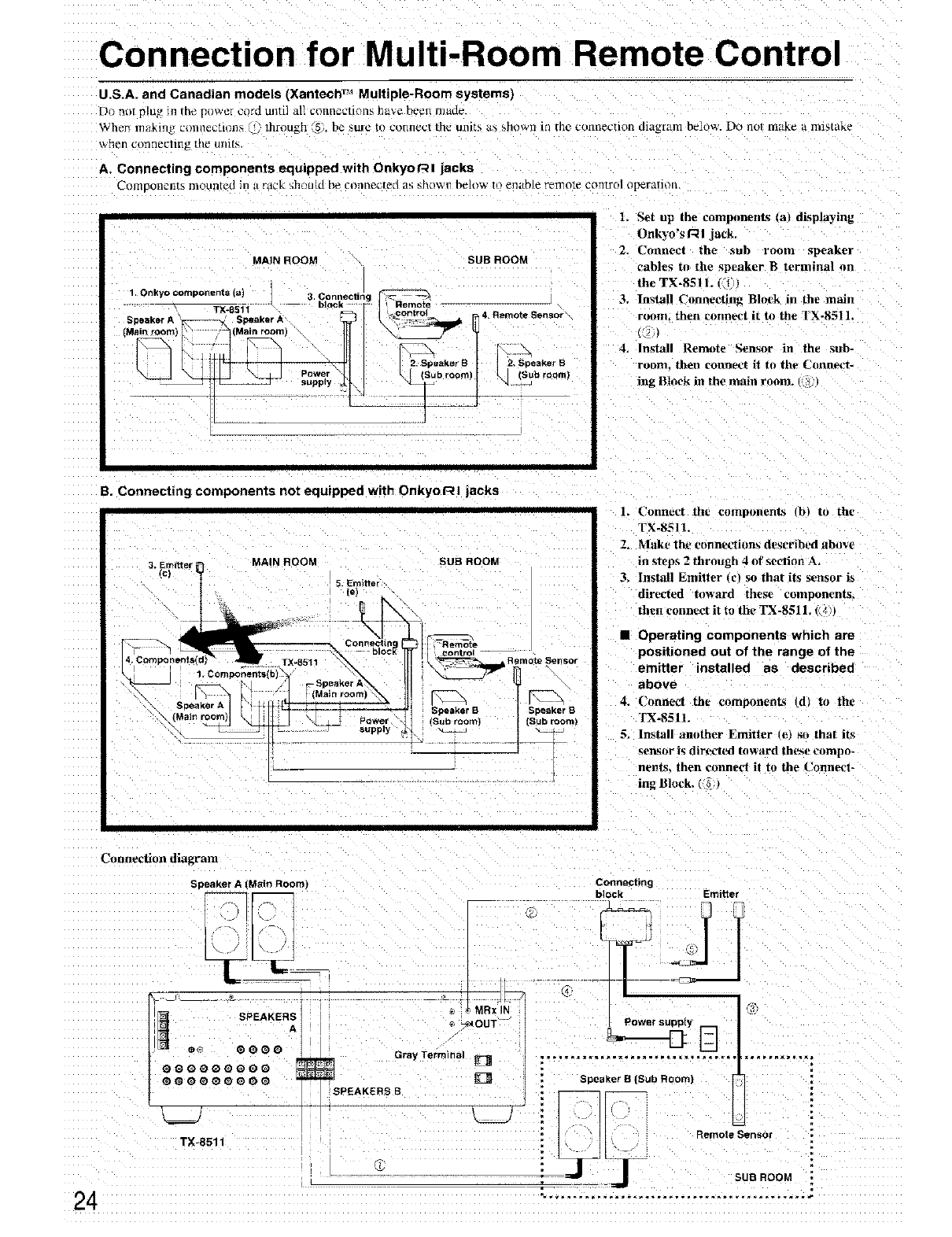
U.S.A. and Canadian models (Xantech TM Multiple-Room systems)
Do nt_t _[u_ m the p_wel cord uJ_til all conn_cti_nls ha_e b_'ei_ rllade,
When makil]g, c_mne_Lmlls S., Through _5, be sure tt/connect th_ units a_ showll Irl the cotnlectlt)l_ dlagr_m b_lo'_,. Do not [llz_kc a llli_take
%h_n ctlnIl_tJllh_ [h_ Ullttt-
A. Connecting components equipped with Onkyot--'-_l jacks
Con/Doneli_S nlonlitcd in a rack hhou{d be t'oinlecte(I _p; _h(iw i1 beh/w tl) enable r_mote eot_tro] operfillOtl.
1. Onkyo components (a)
MAIN ROOM SUB ROOM
511 3' blC°_n_ectir] "g IRemote
T;(-8 akerA t__controt 4Rerane Sensor
Power M k[ tSubroorn)| _ (Sub ooml
L Set up the compnnents lal displaying
Onky0"s RI jack.
2. Connect the sub room spezker
cables to the speaker B terminal on
the TX-8511. (_1,)
3, Install Connecting Bh_ck in the main
room. then connect it to the "l X-8511,
4. Install Remote Sensor in tile _ub-
ronm. then connect it to the C,mnect-
ing Btnek in the main room. _
B. Connecting components not equipped with Onkyor_l jacks
MAIN ROOM
3. Emitter
5. Emitter
{e)
\ __ supply
SUB ROOM
Speaker B Speaker B
(Subroom) (Sub room',
I
C_mnecfion diagram
Speaker A (Main RoOm)
l. L'onnect the components b_ to the
FX-851 l.
2. Make th_ eonnet_iorts described abRv_
_nstt, ps 2 through 4of section A,
3. Install Emitter _t'_ so that its sensor i_
directed toward thv_, components.
fl_en connect it to |he TX-8511.
• Operating components which are
positioned out of the range of the
emitter installe¢ as describe€
above
4. Connect the _._mponent_ (d) to th_
1"X.8511.
5. Install another Emitter _c_ _o that its
sensor is directed h_ward these compo-
nents, then co_me_'t it to the Conne_.t-
ing Block, (_)
Connecting
block Emitter
TX-8511
i
_j
Speaker S (Sub Room)
Connection for Multi-Room Remote Control
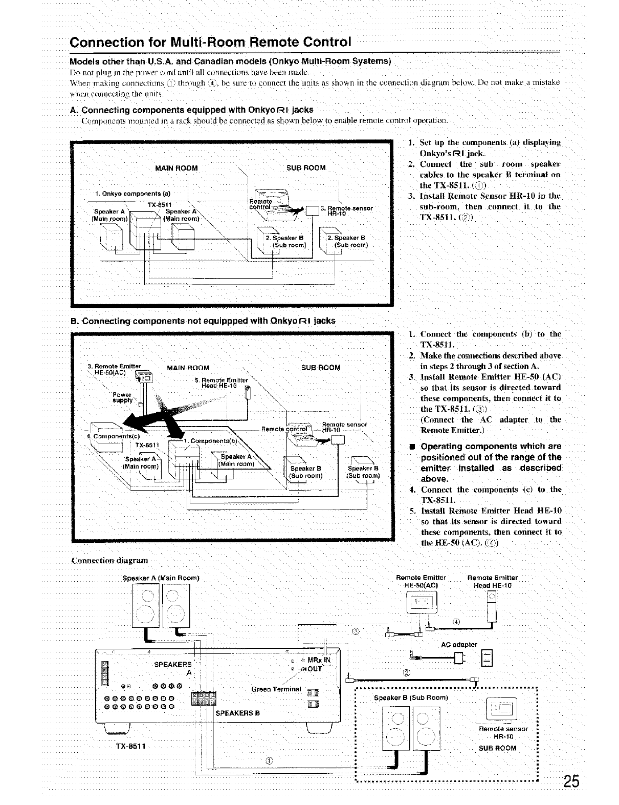
Models other than U S A and Canad an mode s (Onkyo Multi-Room Systems)
Do nor ping mthe p_ wet cilrd until :d/ct_Tln_:tiims have been mallc
X_'h__n lll_lkln_ cllall_l'L)ons 1throll_h 4 ht _ _llt_ Io collnec! [ll_ unl[_ a_ sho_n ill _h_ c0111_e_tlon die,ram _c]_l_. Do no( Inak_ d Iltibt_k_
_tlCI] _OIllle_'liIIg .lle uI/nN.
A. Connecting components equipped with Onkyo r_ I jacks
1_ _/_llpon_2_R_, m@.lnt_d ]n _l'tlgk _hould b_ _.'onllL_ct_'d _ls 5howrt below tO _n_tble i_m_lt_ _J_IIflTO] Op_I'_H_IL
1, Set up the components Ca) displaying
Onkyo_s I_ I jack
MAINROOM SUBROOM 2. Uonneet the sub room speaker
cables to the speaker 14 terminal on
the TX-851L " :
1.On_yocomponents(a) I_t.
,mRa_ote ,3. Install Remote Sensor HR-10 in the
TX-8511 eontro _*_- 3, Remotesensor sub-room, then connect it to the
Mainroom) (M I I_- TX-8511. (' 2t
2. Speaker B 2, Spea_er B
B. Connecting components not equippped with Onkyo t_ I jacks
3. Remote Emttter MAIN ROOM SUB ROO_
"HE-f01ACI
Power
supply
4, Components(cJ
_TX-8511
"\\, (Main roomI
i I
1. Connect the eomponent_s _b} to the
TX-_L_It.
Z. Make fl_e connedioas de_b_d _bov_
in steps 2 through 3of s_ction A,
_. Install Remote Emitter HE-50 (AC
so that its sensor is directed toward
theae components, then connect it to
the TX-8511. t_
Connect the AC adapter to the
Remote Endtter,
• Operating components which are
positioned out of the range of the
emitter installed as described
above.
4. Conne_'| the eompotlent_ _c_ to the
TX-8511.
5. In_tall Remote Emitter Head HE-J0
so that its sensor is directed toward
these components, then connect it to
th_ HE_SI) _AC), ((_',1
Connection diagram
Speaker A (Main Room)
_MRx)N
SPEAKERS _ _OUT
A
e_ @O@_ Green Terminal
Remote Emitter Remote Emitter
HE-50(AC) HeadHE-10
AC adapter
HR-IO
TX-S511 SUB ROOM
25
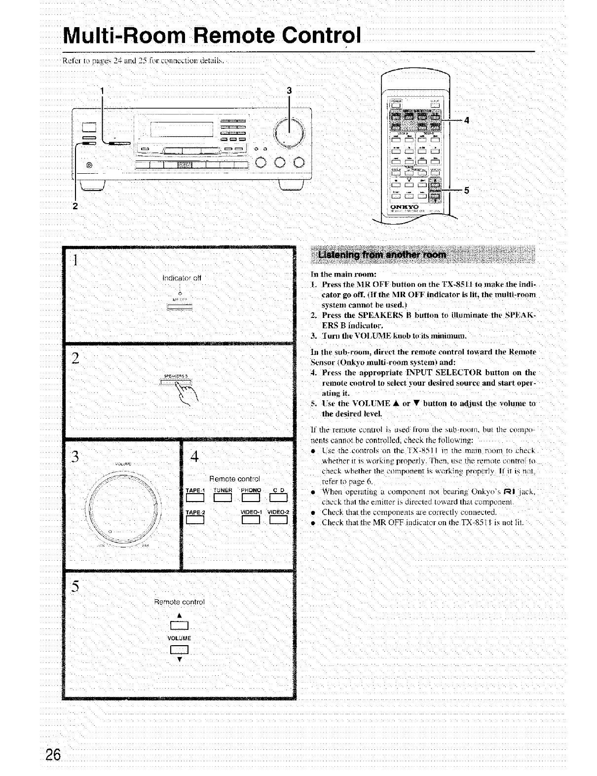
Multi-Room Remote Control
Retel tit _age_ 2=t and 25 ftlr conllectioll deItlll_
13
L=J L.._.
2
--5
oNX,Tz9 ,,
1
ndlcator ,qff
2
3
.... _ II
4
qemDte contro
TAPE-1 TUNER PHONO C D
TAPE-2 VIDEO-1 VIDEO-2
........ L __ __
5
Romo_a control
EEl
VOLUME
In the main room:
LPresstheMROFFbultanontheTX_8-_ll to make the indi-
eator go off. (If the MR OFF indicator is lit. the multi-room
_2_steIll cannot be used,
2. Press the SPEAKERS Bbutton to illuminate the SPEAK-
ERS Bindicator.
3= 'I utal the VOI,UrvlE knob to its mitdmum,
In the sllh-rooln_ dir,_,t the remot_ control tm_ard the Remote
Sen4or _, )Ilk3 oillu]ti-room systeml and:
4. Pres_ th_ appropriat_ INPUT SELECTOR button on the
remote contrcfl to select your desired source and start oper-
ating it,
5 l'se the VOLVME & or •button to adjust the volume m
the desired levd
If the relnole colltlo] i_ u4ed Irolll tile MIb-roOI/L hut the c{llnpo
nents cannot be controlled. _'heek the tolh>wmg:
•Use the controls on the IX-8511 m the mare room m chec_
•ahether It1'_,aorking properl> Then. Ise the remote c(liltrot to
check whether the ct_mponeni i4 w_lrking properly If il is n
refer t_ _age 6.
• When {lperalln_ a COlllpOnelU I]o[ DI2Arlllg t)lfiky(_ 4 RI dll..
£tlC_K _nal rile emit*er is directed /ow;,.rd that coi1]porleill.
• Check thai the colllpOtlPI/lS ar_" corrt_cllV connecmo
•CheckthattheMROFFindJcatoron theTX 8_]1 is notlit
26
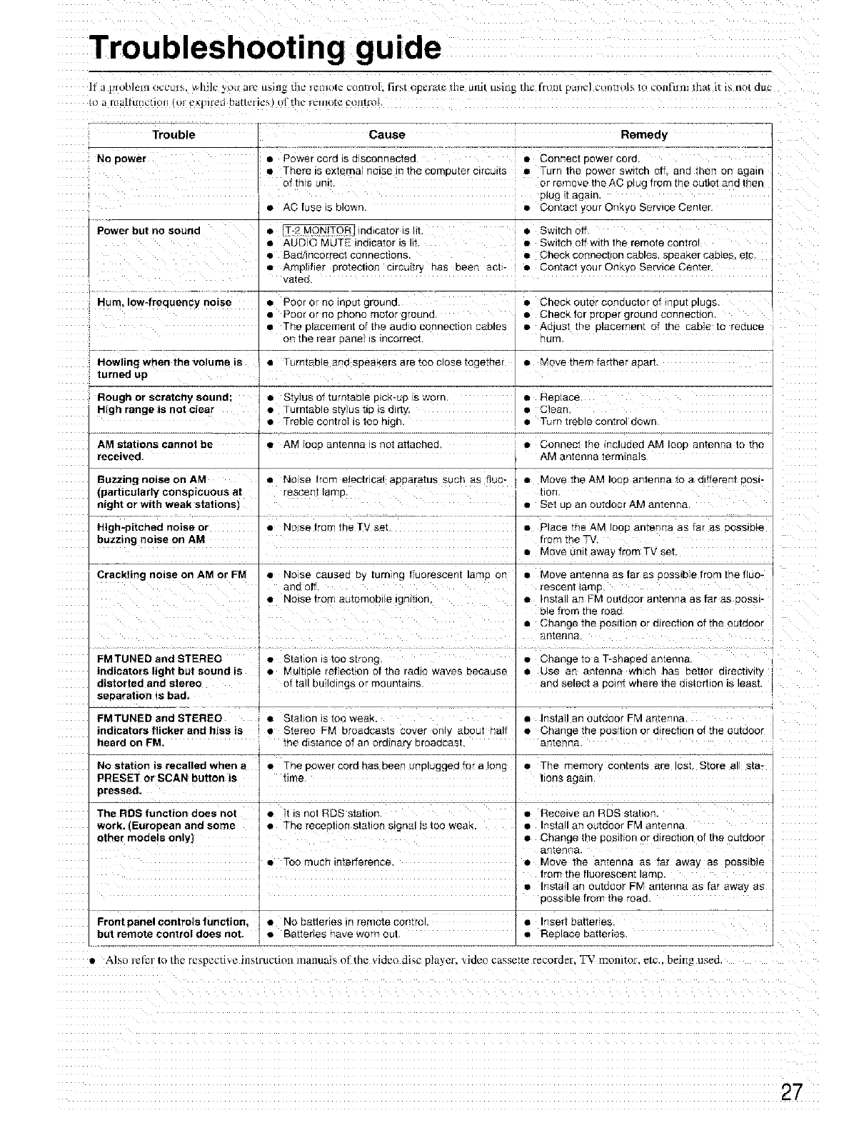
Troubleshooting guide
]J _ plob]_lll ouCu[5, Wlli]C ytlu ilK" tl_lll_ _bc ]UIIIOI{_ Ct)l][]{3]. l'ilH[ t)p_lL_{C |b_ UILIt uf;illg tlI_ fIotlt {Yam:] _OlllIO[_ to L't!llfJlllt |h_a d is lie| du_
{ll a Ittullunctl_)l _}I e_|]lleg hatleil_2s (tl _b_ _ lcluta_ coIlr[nb
No power
Trouble Cause
• Flower cord IS oJscoRnecte(3
• There is e×ternal noise {Rthe computer circuits
of thrs umt
Power but no sound
•A0 ruse IS OlOWn.
Remedy
•Connect Dower coro.
iTurn the cower sw_cn off. and then on agalr
or remove the AC D]ug from the outlet and then
plug ]1again.
• Contacl your Onky0 Serwce Cente_
• IT-2 MONiTOR_lndlcator Is ht. • Switch off.
• AUDIO MUTE indicator is lit • Switch offwith the remote control
• Bad/incorrect connections. • Check cortnect{on cables, speaker cables, etc
• Amphtler protection circuitry has been ach- • Contact your Onkyo Service Center
vated_
Hum, Iow4requency noise • Poor or no input ground. • Check outer conductor of _nput plugs.
• Poor or no phono motor ground. • Check for proper ground connection
• The placement of the audro connection cables • Adlust the placement of the cable to reduce
on the rear panel is incorrect, hum.
Howling when the volume is •Turntable and speakers are too close together
turned up
Rough or scratchy sound; • Stylus of turntable pick-up ts worn.
High range is not clear • Turntable stylus t}p _sdirty,
•Treble controt is too high.
AM stations cannot be
received.
• Move them farther apart.
• Replace.
•Clean,
• T,_rn treble control down
Buzzing noise on AM
(particularly conspicuous at
night or with weak stations)
High-pitched noise or
buzzing noise on AM
• AM loop antenna is not attached • Connect the included AM loop antenna to the
AM antenna terminals
• No se from electrical apparatus such as duo- • Move the AM loop antenna to a different posl-
reseenl lamp tion
• Set up an outdoor AM antenna
• Place the AM loop antenna as far as possible
from the TV.
• Move unit away from TV set.
Crackling noise on AM or FM • Norse caused by turning fluorescent lamp on • Move antenna as tar as possible from the fluo-
and off. rescent lamp
• No_sefrom automobile _gn_t_on. • Install an FM outdoor antenna as far as poss_-
hie from the road
,• Change the pos[lion or direction of the outdoor
, antenn&
e
FMTUNED and STEREO • Station is too strong Change to a T_shaped amenna
indicators light but sound is • Multiple reflection of the ra&o waves because • Use an antenna wh ch has better direcbvity
distorted and stereo of ta}l buildings or mountains and select a point where the distortion is least.
separation is bad,
FMTUNED and STEREO , • Station is too weak. •Install an outdoor FM antenna.
indicators flicker and hiss is • Stereo FM broadcasts cover only about half • Change the postion or direction of the outdoor
heard on FM. me distance of an ordinary broadcast, antenna.
No station is recalled when a • Thepowercordhasbeenunpluggedforalong • The memory contents are ]ost. StQreal sIa-
PRESET or SCAN button is time hone again
pressed. I]
The RDS function does not •]t is not RDS station •Receive an RDS station.
work, (European and some • The reception station signal is too weak. • Install an outdoor FM antenna.
other models only) _ • Change the position ol direction of the outdoor
antenna.
• Too much interference, • Move the antenna as far away as possible
' from the fluorescent lamp.
, • Install an outdoor FM antenna as far away as
possible from the road.
Frontpanelcontrelsfunction, • No batteries in remote control. • Inseflbatteries.
but remote control does not. • Battahes have worn out • Replace batteries
• Alsu I_l_] to tb_ re_peetl_¢ lfiS[l_Uellnn ]llanufil_, ei ire VIL]eO £11_._ p a'_cr, qdeo cassette recorder, _,' monitor. _fc being usect.
27
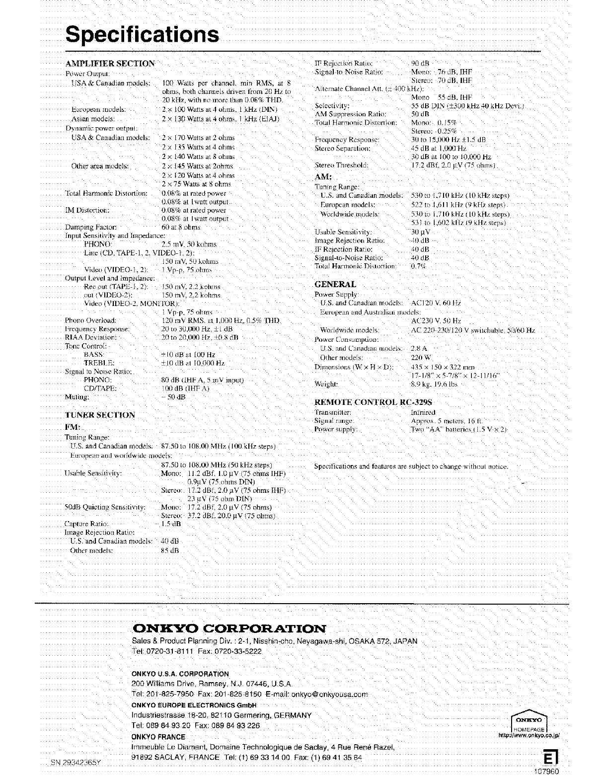
Specifications
AMPLIFIER SECTION
PoV* e[ O/lII3UI
USA & Canaman moacl_
E_I OPhiR {Hod_lY.
Asian model_
DytlAHIIC pt_w_I tKl[l)u!
USA &Canadian modeE:
Other area models:
Ibtal Harmonic Dlstortlon
[M Distorfior
Damping Factor
100 Waits per channel min RMS. at 8
ohms both channels driven from 20 Hz {
20 kH2 with ml more than 0 08% THD
2 x i00 W_ts at 4 ohms. I kHz DIN1
2×130W_t_at4ohms I kHz LIAJI
2X170 Watts at 2 ohm_
2 × J 35 Warts al 4 ohmq
2 × 140 Watts at 8 ohms
× ]45 _.¥att_ at 2ohm_
< 120 Watts at4ohm_
2 x 75 Watt_ at 8 ohm_
!1.08% at I watt outpm
O.U8% at rated power
).08_ at Iwatt oumul
[npm _ensltlvity and hnpea,ulce
PHONO' 2.5 mV 50 kohn
Li_ie /CD. TAPE 1 2. VIDEO 1 2
gO iil_ _0 kollt{lS
Videi3 VIDEO-L 2h Vp-p 75 ohms
Ouwut Ievel and Impeuance:
Rec out _APE-] 2 50 Ink[ 22 _.onm_
al VIDEO 2 _0 inV. 22 kohms
Vmec VIDEO_2. MONII'OR
t _ g-p. 75 ohm_
Phono Overload.
req_lency Re,spon'_e ¸
RIAA Dc_lauon:
T_[ic Col/Irol:
BASS
TREBI E:
gnal to No_e Ratio.
PHONO"
CD,WAPE
MUlmg:
tel) m'_ RMS at Id/*#l H," 05q, FHD
20 to 30.IR10 Hz t { dR
20 to ?0 tRI{}Hz +0 N dlt
+10 dB at [OOHz
+10 dB al lO oRJHz
80dg [HP A. 5 mV mpm
30dB IHFA
50 dB
TUNER SECTION
FM:
I'ml lg Rang_:
{r.S. and Uanad_an models 87 50 t_ 108 011MHz lEO kHz steD_]
87.50_o 10&00MHz 5(IkHzsteps
Usable Sensitixit_. Mon_,: 11.2 dBf. 10 uV 75 ohms [HF
I _ttV 7_; ohms DIN
IF Re _'cdon Rata 9(} dR
Signal to Noise Ratio: Mona 76 dB. [HF
qtere_v 70dB IHF
Allerflate {Jlial)nel Atl _ _,tt_ r.nz
Mona _5 dB. IHF
Selectivity
AM Surmresdrm Ratill
Total Harmonic Dislortitm
Frt2qu{?llcy Rcsp lille
Stereo Threshold
AM:
Tumng Range
U.S. and Canadian models.
El mpean nlodel_;:
World_a Ide modes
l IsahJe Seoaltlvity
hnage Rejecuot* Ralio
IF R¢lecdon Ratt_
_gnal-to-No_se Ratio:
Total Harmonic Dislorfion
55 dB DIN _±300 kHz 4(} kH7 Devl.
S0 dB
Mona: O [5_A
Stemo: E.25_
_!l m 15.000 It_ +1 5 dE
4'; dB at 1 000 H_
_0 dB at/0t') t_ 10.000 Hz
172 dBf. 2Z aV (75 _hm_r
530 m L710 kHz I0 kHz stcp_l
522 to E611 k[17 vJkH2 _te _s
531) _u 7 I(} kHz I1(} kHz slep
53] to IO(P kllz/9 kHz _Le,,_
_/J U¥
ill dB
4(}dB
4(}dB
0,7_
GENERAL
Power SuppP
U.S. and Canadlas_ modcE _CI20 V_60 ltz
Et{IIJpedli t_lld Au_/I_li_II lnl idcq _.
AC23(} V. 50 Hz
Worldwide moclm_ AC 2?0 231# 12(} V switchable Nil6(} Hz
Powel Cllll_l_mp_K_[
U S. and Ualnld_ xlels ? 8 a
Odrer models: _-20 W
D_men_mns IW x H * D 4 _s × 150 x 322 mm
7 I/_*'X171_"A 12 IUI6"
REMOTE CONTROL RC-329S
I raflMlil_t_r [ nlrai'¢* d
_i_lldl rRll_2 _,ppFOX 5 ffI_/CyS IO H
P_wer _ Ippty "1wu "'AA" batleru,_ 1.5 V x 2
Specifications and f?'atare_ are _ubl¢ci _* cflatl_ze _,_dhoul mltl_e
50dB Ouk'tmg Sen_fivdv.
( "aptura Ratio
Image Rejection Ratio:
L.S and Canadian model€ at} dB
Other models 85 dB
Stereo !7.2 dBI. ZO JV 175 ohm_ ItlF
23uv 75 ohmD[N
Mane 7.2 dBtl 2.0 uV (75 ohms)
Stcr_:o: 37.2 dBf 20.0 uV 175 ohmsi
1.5 dR
ONKYO CORPORATION
Sales & Product Planning Div. 2-1 Nmshin-cho. Neyagawa_shi. OSAKA_72 JAPAN
Tel' 0720-318111 Fax. 0720_33-5222
SN 29342365 _
ONKYO U.S.A. CORPORATION
200 Williams Drive. Ramsey. NJ 07446 US.A
-el: 201-825_7950 Fax: 201-825 8150 E-mail" onkyo@onkyousa.com
ONKYO EUROPE ELECTRONICS GmbH
Industnestrasse 18-2(} 82110 Germefir_g. GERMANY
Tel 089 84 93 20 Fax: 089 84 93 226
ONKYO FRANCE
ImmeuNe Le Diarna_t Domaine Tecnnomg_que de Saclay, 4 Rue Ren_ Razel
91892 SACLA'r FRANCE Tel: tlI69 33 14 00 Fax. I1169 41 35 84 E-1
107960
