OPCOM X0738CSF 2.4GHz Wireless Digital Transceiver Module User Manual Features
OPCOM Inc. 2.4GHz Wireless Digital Transceiver Module Features
OPCOM >
manual

User Manual
CUSTOMER
PRODUCT 2.4GHz Wireless Digital Transceiver Module
MODEL NO. DRF-TR001
DATE Nov. 2007
義聯科技股份有限公司
ELANsat Technologies Inc.
5F, No.12, Innovation Road Ⅰ,
Science-Based Industrial Park,
Hsin-chu, Taiwan, R.O.C.
TEL:+886-3-563-5105
FAX:+886-3-563-5107
http://www.elansat.com
E-mail:sales@elansat.com
DOC NO:Preliminary 1.0

100RT-FRD
Wireless Digital Transceiver ELANsat
Page of 7
2007.12.06 www.elansat.com
Version: 1.0
1
Features
Auto ACK & retransmit
On the air max. data rate 2Mpbs
Digital interface (SPI) speed 0~8 Mbps
Software selectable channel form 2402MHz to 2478MHz (77 Selectable channels)
Short switching time enable frequency hopping
Power supply range: 3 V to 3.6 V
Minimum number of external component
Low power consumption: 3.3V, 30mA
Transmission distance: 100 m (Line of sight)
Outline: 23.2 x 20.8 x 4.3 mm
CE 300 328 and FCC 15.247 certificated
Applications
Keyless Entry
Wireless data communication
Alarm and security systems – Wireless home security, Video Door Bell, Video door phone
Home automation
Surveillance – Wireless P-CAM, Video Baby Monitor
Automotive – Wireless Vision-Based Robotic System, Automotive Accessory
Telemetry
Intelligent sports equipment, Video Rockie-Talkie
Industrial sensors
Toys – Camera Radio Controlled Toy
Wireless Photo Frame
Benefits
Ready for production
Reduce time to market
Remove complicity of RF design
No RF experience require
No expensive RF equipment require
Plug and play
No fuse on turning and trimming
No need for expensive external antenna
DRF-TR001
Wireless Digital Transceiver ELANsat
Page of 7
2007.12.06 www.elansat.com
Version: 1.0
2
Specification
Limits
Parameter MIN TYP MAX Unit
Power Section
Supply Voltage 3 3.3 3.6 V
Supply Current in Tx mode 23 30 33 mA
Supply Current in Rx mode 17 18 19 mA
Digital Input Section
High level input voltage 2.1 2.25 Vpp
Low level input voltage 0 1.08 Vpp
Digital Output Section
High level output voltage 2.7 3.6 Vpp
Low level output voltage 0 0.3 Vpp
RF Section
Frequency Range 2400 - 2525 MHz
Channel Bandwidth 1.8 2 MHz
TX Power 12 14 16 dBm
RX Sensitivity -81 dBm
Operation
Operating Temperature -10 - +60 ℃
DRF-TR001
Wireless Digital Transceiver ELANsat
Pin Configuration and Mechanical Information
Page of 7
2007.12.06 www.elansat.com
Version: 1.0
3
DRF-TR001
Wireless Digital Transceiver ELANsat
Pin Description
No. Symbol Function
1 VCC
Power Supply
2 GND
Ground
3 IRQ Maskable interrupt pin
4 MISO
Master Input, Slave Output (output from slave)
5 MOSI
Master Output, Slave Input (output from master)
6 SCK
Serial Clock (output from master)
7 CSN
Chip Select
8 CE
Chip Enable Activates RX or TX mode
9 X
10 GND
Ground
Page of 7
2007.12.06 www.elansat.com
Version: 1.0
4
DRF-TR001
Wireless Digital Transceiver ELANsat
Page of 7
2007.12.06 www.elansat.com
Version: 1.0
5
PCB layout guideline
Any metal (including PCB track and holding screw) around the antenna will result in changing
impedance and radiation pattern of the antenna. These two parameters are the most important for
antenna performance. Reserve space around the antenna as much as possible.
Connect all parts as close as possible to the pins of module and reduce the length of routing
traces, to help on good audio performance, proper antenna pattern and EMC.
When designing the receiver module in wireless speakers and headphones, the important design
considerations are as follows:
1. Keep metal objects away from the antenna by 3 cm distance at least to avoid degradation on
the antenna. For example, speaker unit, transformer, adaptor, wire, cable and other big metal
object beside antenna will degrade the antenna performance.
2. Use regulated DC-power-supply to the modules, and separate the DC-power-supply of module
with the other circuits.
Antenna
1. Wire Antenna: A 27~31mm plastic-covered wire can be used as antenna. In principle, 31mm
length is for a wire without any cover or very thin cover. The thicker of the cover, the shorter of the
antenna length. Try various length for a certain wire to optimize the transmission distance.
2. Antenna Soldering:
DRF-TR001
Wireless Digital Transceiver ELANsat
Operation
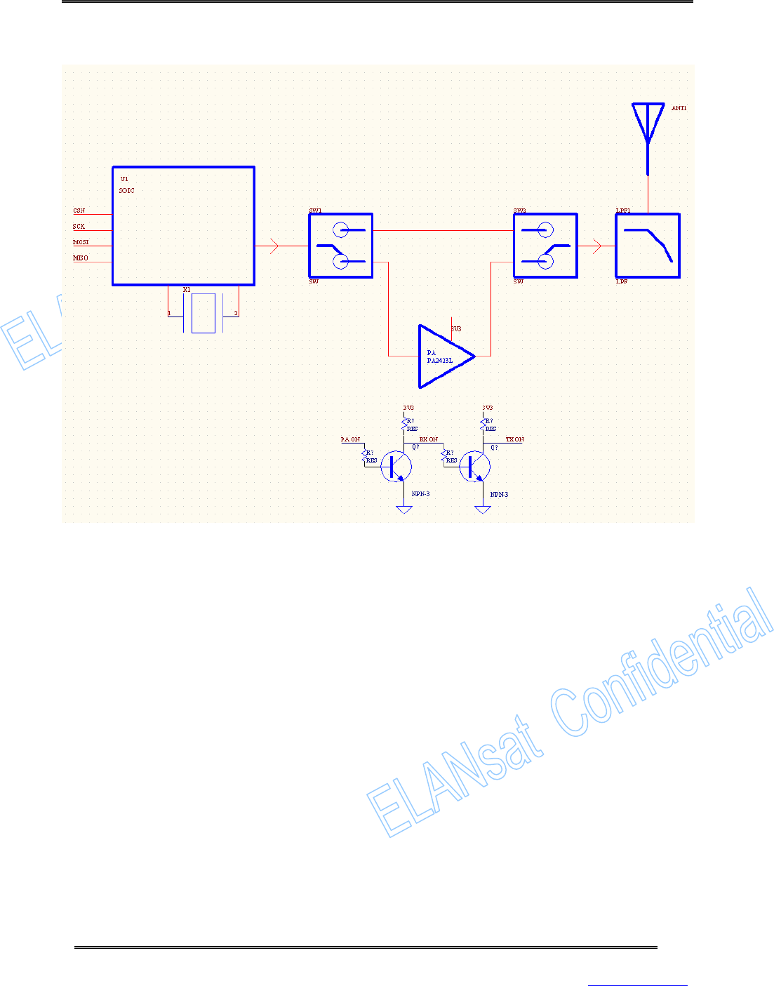
Block Diagram of DRF-TR001
The SPI data then is fed to SOIC for encoding, FSK-modulation, frequency conversion, and
amplification.
RF signal between SOIC and antenna is separated to two paths: transmission and receiving (by
two RF switches). Transmitted RF Signal from SOIC is following by a power amplifier to increase
output power and transmission distance.
Page of 7
2007.12.06 www.elansat.com
Version: 1.0
6
RF signal between SOIC and antenna is separated to two paths: transmission and receiving (by
two RF switches). Transmitted RF Signal from SOIC is following by a power amplifier to increase
output power and transmission distance.

DRF
-
TR
00
1
Wireless Digital Transceiver
ELANsat
This device complies with Part 15 of FCC Rules and RSS-Gen of IC Rules.
Operation is subject to the following two conditions:
1) This device may not cause harmful interference, and
2) This device must accept any interference received, including interference that may cause
undesired operation.
Note: This equipment contains module, FCC ID: UDRX0738CSF and IC: 0976B-
D0738CSF,
which qualifies as an
UNLICENSED MODULAR TRANSMITTER per FCC Public Notice DA
00-1407 and RSS-Gen Section: 7.1.1. It has been tested and found to comply with Part
15.249 of the FCC Rules and RSS-210 issue 7:2007, Annex 2.9.
Required labeling.
Any device incorporating this mod
ule must include an external, visible, permanent marking
or label
which states:
“Contains FCC ID: UDRX0738CSF”
“Contains IC: 0976B-D0738CSF”
Failure to comply with this requirement will void the user’s authority to operate any device
that incorporates this module.
This equipment complies with FCC/IC radiation exposure limits set forth for uncontrolled
equipment and meets the FCC radio frequency (RF) Exposure Guidelines in Supplement C
to OET65 and RSS-102 of the IC radio frequency (RF) Exposure rules. This equipment has
very low levels of RF energy that it is deemed to comply without testing of specific
absorption ratio (SAR).
To reduce potential radio interference to other users, the antenna type and its gain should
be so chosen that the equivalent isotropically radiated power (e.i.r.p.) is not more than that
permitted for successful communication.
Page
7
of
7
2007.12.06 www.elansat.com
Version: 1.0