OPISYS orporated USHR-0819SS Dual Band CDMA Repeater User Manual
OPISYS Incorporated Dual Band CDMA Repeater
Manual
ACE Antenna Corp.
Dual Band Repeater Manual
Model : USHR-0819SS
This document contains confidential and proprietary information that belongs to
ACE Antennas. Using any of the information contained herein or copying or imaging
all or part of this document by any means is strictly forbidden without express
written consent of ACE Antennas.

ACE Antenna Corp.
Content
1. System Introduction
2. Specifications
2.1 Electrical Specification
2.2 Mechanical Specification
2.3 Environmental Specification
2.4 Functional Specification
3. System Functions
3.1 Operation and Monitoring Functions
3.2 Characteristics and Features
4. Installation
4.1 Introduction
4.2 System Components
4.3 Installation Location
4.4 Installation Method
5. Trouble Shooting
6. Drawings
7. Marks and Packaging
7.1 Outside Markings
7.2 Packaging Method
ACE Antenna Corp.
1. System Introduction
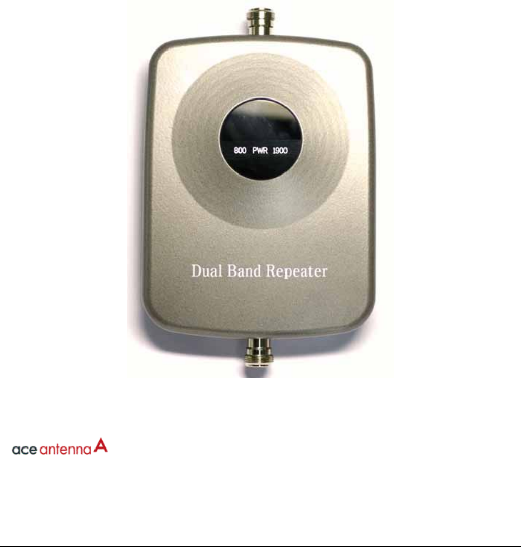
This unit is a repeater for the US Cellular and PCS frequencies. The unit allows
coverage in areas where the base station signals are weak. The unit is installed between
the base station and the mobile phone and allows better mobile phone coverage by
amplifying weak base station signals.
Main Features
- To maintain constant power level, automatic level control (ALC) function is
used.
- In cases of unexpected errors or power levels, the unit will begin its
automatic shutdown sequence.
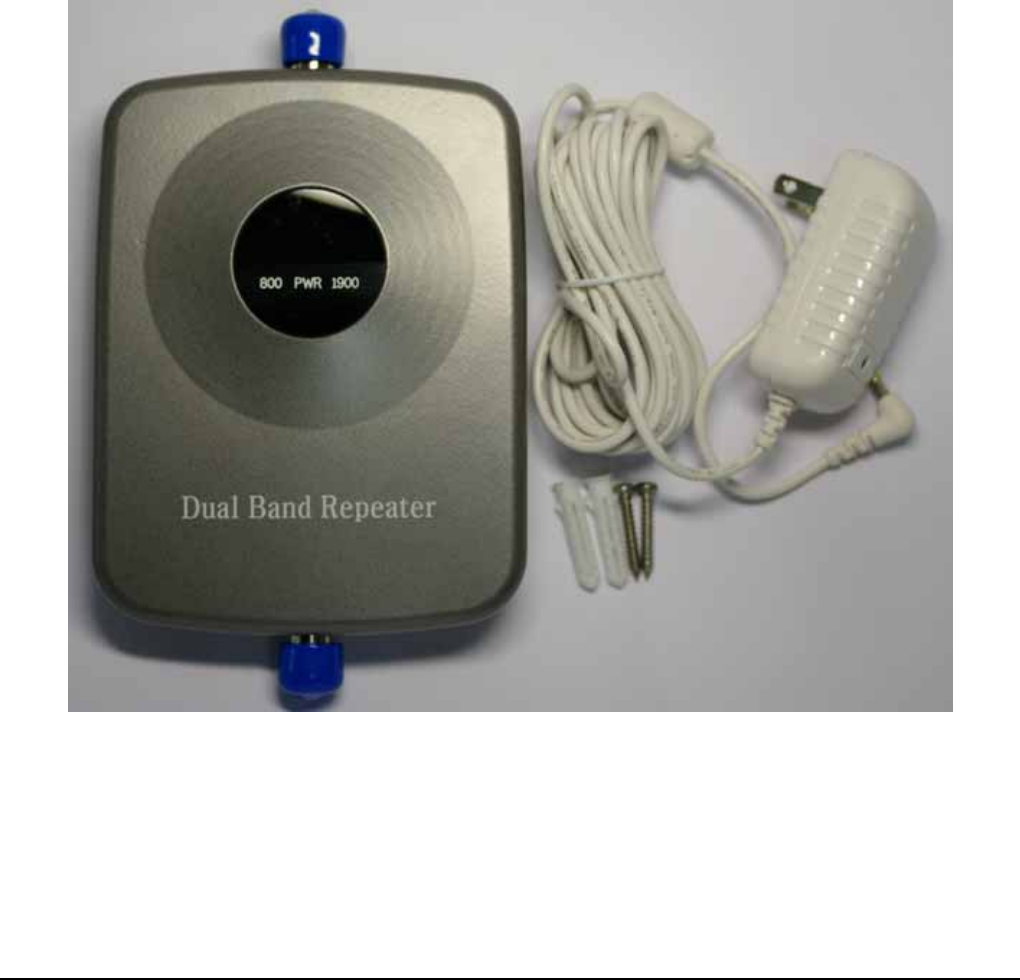
System components are below.
Signal Repeater ② Wall Mount Bolts ③AC/DC Adapter
2. Specifications
①
②
③
①

ACE Antenna Corp.
2.1 Electrical Specification
Item Specifications Note
Frequency Range
Down Link 1930 ~ 1990 MHz US PCS 1900
BW: 60MHz
Up Link 1850 ~ 1910 MHz
Down Link 869 ~ 894 MHz Cellular 800
BW : 25 MHz
Up Link 824 ~ 849 MHz
Input Power limit
Down Link -28dBm US PCS 1900 ALC : >25dB
Up Link -28dBm US PCS 1900 ALC : >25dB
Down Link -28dBm Cellular 800 ALC : >25dB
Up Link -28dBm Cellular 800 ALC : >25dB
Output Power
Down Link +12dBm/1FA US PCS 1900
Up Link +12dBm/1FA
Down Link +12dBm/1FA Cellular 800
Up Link +12dBm/1FA
Gain
Down Link 65dB (±2dB) US PCS 1900
Up Link 65dB (±2dB)
Down Link 65dB (±2dB) Cellular 800
Up Link 65dB (±2dB)
Ripple < 6dB US PCS 1900
< 5dB Cellular 800
Noise Figure < 8dB US PCS 1900 / Max Gain
< 8dB Cellular 800 / Max Gain
Propagation Delay 1us max US PCS 1900/ Cellular
800
VSWR ≤ 2.0 : 1 US PCS 1900/ Cellular
800
Output Power@1dB Compression +16dBm/CW US PCS 1900/ Cellular
800
Output IP3 +31dBm US PCS 1900/ Cellular
800
Down/Up Link Shutdown Level +14dBm/Total (±1dB) US PCS 1900/ Cellular
800
Spurious
±885KHz -45dBc/30kHz US PCS 1900, 1FA
±1.98MHz -50dBc/30kHz US PCS 1900, 1FA
±750KHz -45dBc/30kHz Cellular 800, 1FA
±1.98MHz -55dBc/30kHz Cellular 800, 1FA
Frequency Stability ≤ ±0.05ppm US PCS 1900/ Cellular 800
GUI Interface RS-232C
Alarm & Status Display GREEN ON POWER
Red-1 ON Cellular TX/RX Overpower Alarm
Red-2 ON PCS TX/RX Overpower Alarm
Power Consumption 5.3V / 1.4A
Input Voltage DC 5.3V / 1.8A AC/DC Adapter
RF Connector N-type Female
2.2 Mechanical Specification

ACE Antenna Corp.
Item Description Specifications Note
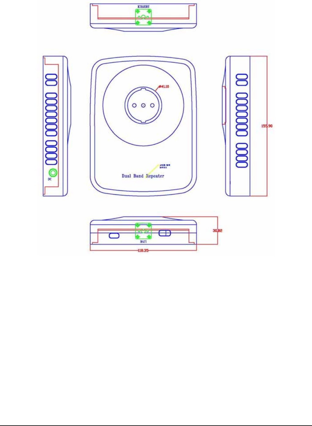
Repeater Dimensions(L*W*H) 119*156*33(mm)
Total Weight <1.5Kg 포장재포함
2.3 Environmental Specification
Item Specifications Note
Temperature -10℃ ~ 40℃
Humidity 5% ~ 95%
2.4 Functional Specification
a. On excessive input power or if oscillation starts, auto shutdown process begins
separately for each Cellular and PCS module in the USHR-0819SS.
b. To maintain constant power level, automatic level control (ALC) function is used.
c. Upon reboot from power outage, the unit will initialize to the last operating state
before the power outage.
3. System Function

ACE Antenna Corp.
USHR-0819SS features and functions are described below.
3.1 Operation and Monitoring Functions
3.1.1 This unit uses 3 LED display to distinguish its operating modes. The green
LED indicates that power is ON. The red LED for the 800 or the 1900 band
is displayed only when that module is shutdown. When the unit is initializing,
all three LED lights blink 1 to 3 times.
3.1.2 To maintain constant power level, automatic level control (ALC) function is
used. When ALC detects excessive input power, auto shutdown process
begins separately for each Cellular and PCS module of the USHR-0819SS.
3.2 Characteristics and Features
3.2.1 The unit is installed between the base station and the mobile phone and
allows better mobile phone coverage by amplifying weak base station signals.
3.2.2 This unit receives the downlink signal from the base station and processes
the signal using the ALC to pass a consistent signal (even if there is a
variation from the downlink signal) to the mobile phone.
3.2.3 This unit receives the uplink signal from the mobile phone and processes the
signal using the ALC to pass a consistent signal (even if there is a variation
from the uplink signal) to the base station.
3.2.4 Up on reboot from power outage or manual ON/OFF, the unit will initialize to
the last operating state before the power was off.
3.2.5 As the mobile phone is roaming out of the unit’s coverage area, the call
hand-off should be smooth and there should be no interruption of the call in
progress.
4. Installation

ACE Antenna Corp.
4.1 Introduction
The optimal installation method is explained below.
4.2 System Components
This unit consists of the power adapter, the signal repeater, and wall mount bolts.
Please check to make sure that you all parts listed here.
4.3 Installation Location
In areas where the base station signal is weak.
ACE Antenna Corp.
4.4 Installation Method
Locate an area in the building or in the room where the downlink signal (base
station to mobile phone) is weak. Then, install the unit on the wall using the wall
mount bolts.
Vehicle Mounted External Antenna
(optional , if available)
A minimum separation distance of 8 inches (20cm) must be maintained between the
user/bystander and the vehicle mounted external antenna to satisfy FCC RF exposure
requirements. For more information about RF exposure , visit the FCC website at
www.fcc.gor
5. Trouble Shooting
To make sure the signal repeater is working, please make sure to check that the
unit’s power is plugged in correctly and then turn the unit on and off.
There are no user serviceable parts in the Dual Band Repeater.
DO NOT OPEN the unit. There is a danger of an electric shock.
Opening the covers of the unit will void all warranties.
CAUTION!
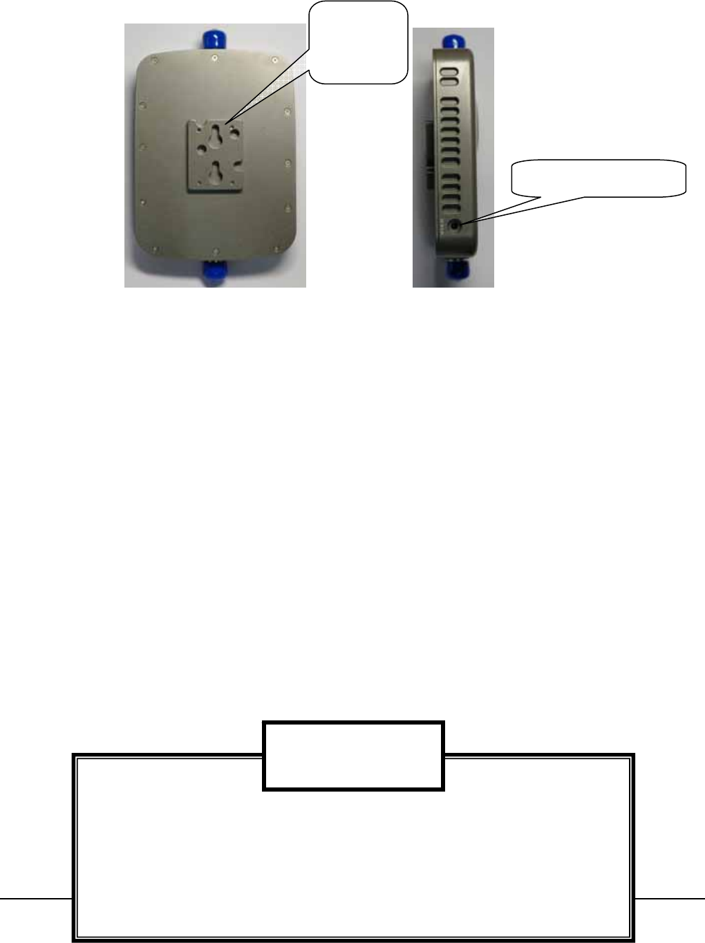
Mounting
Bracket
Adapter Plug-In
ACE Antenna Corp.
6. Drawings
7. Marks and Packaging
7.1 Outside Markings
z The unit should display the manufacturer’s logo and it may also display the customer’s
logo.
z The unit should display the model, the serial number, and FCC Certification number.
7.2 Packaging Method
z To protect from shipping, the unit should be packed using the export standard packing
procedure.
z Corrugated box should be used for outside packaging and foam padding should be used for the
inside to protect the unit during shipping and handling.

ACE Antenna Corp.