OPISYS orporated USHR-1900H 1900 MHz GSM CDMA Bi-Direction Amplifier User Manual USHR1900H 1
OPISYS Incorporated 1900 MHz GSM CDMA Bi-Direction Amplifier USHR1900H 1
UserManual.wiki
>
OPISYS orporated
>
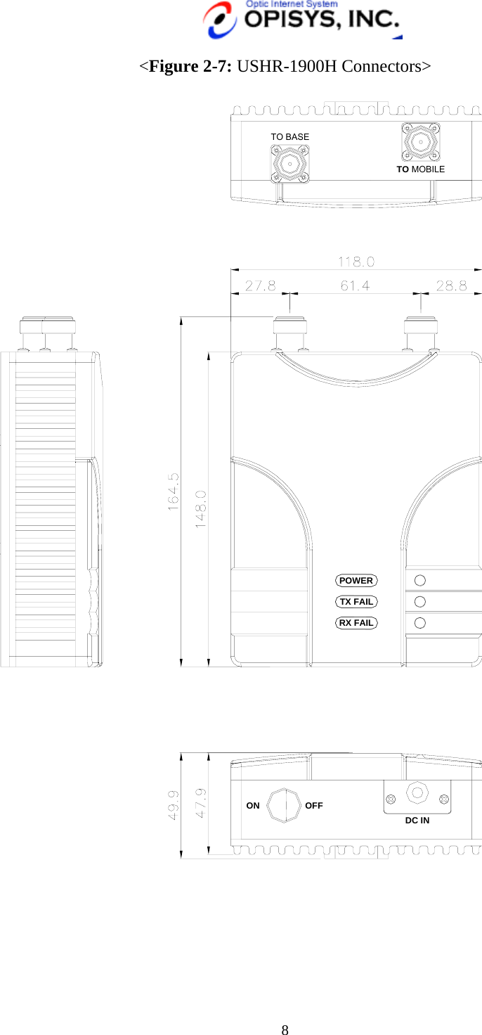
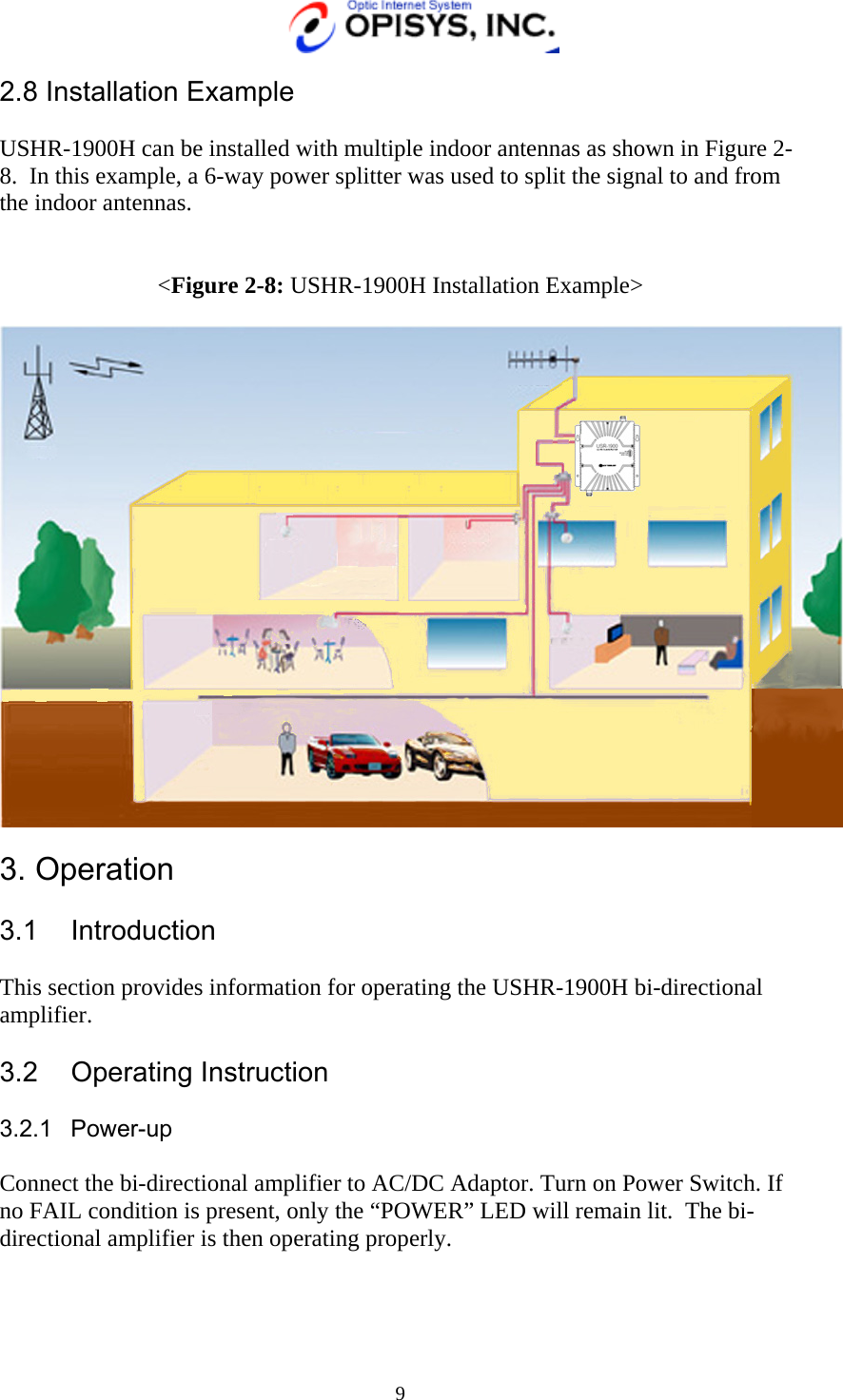
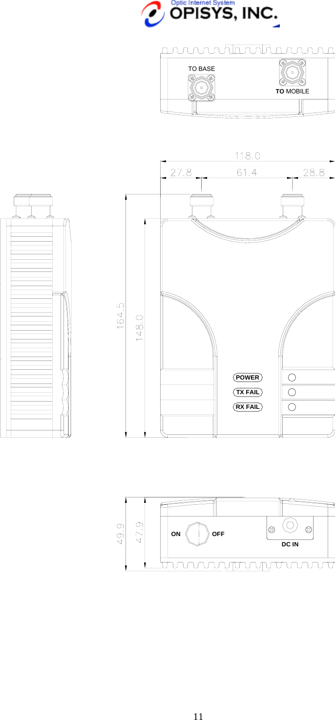
USHR 1900H User Manual
Users Manual
Navigation menu
Upload a User Manual
Namespaces
Wiki Guide
HTML
PDF
Info
Views
User Manual
Discussion / Help
Navigation