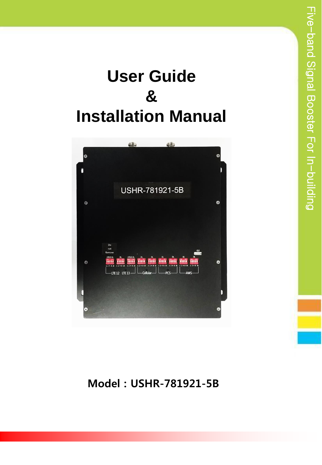
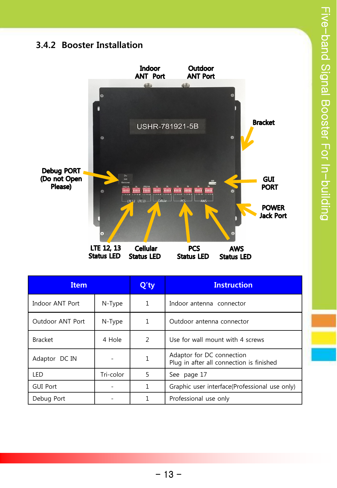
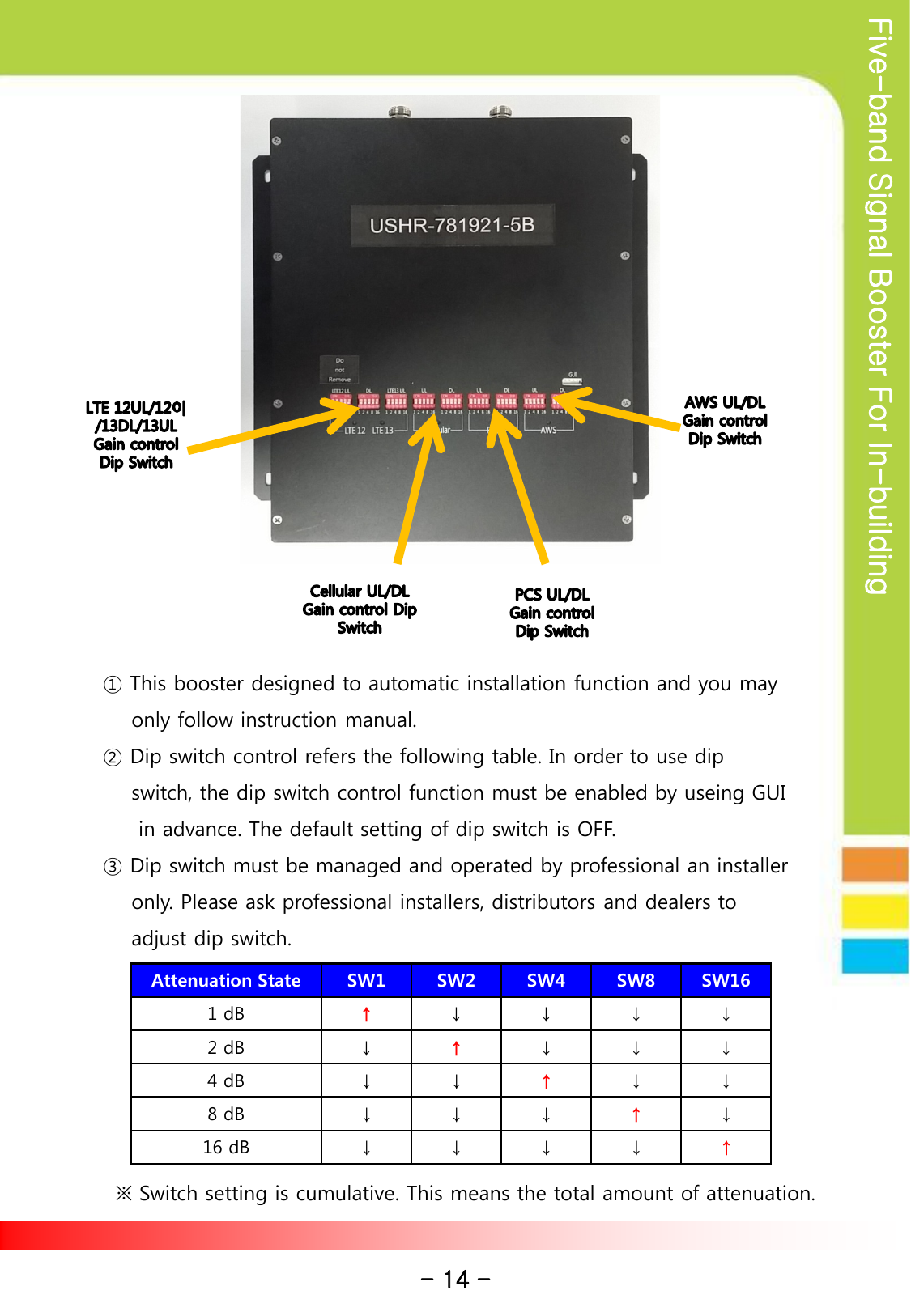
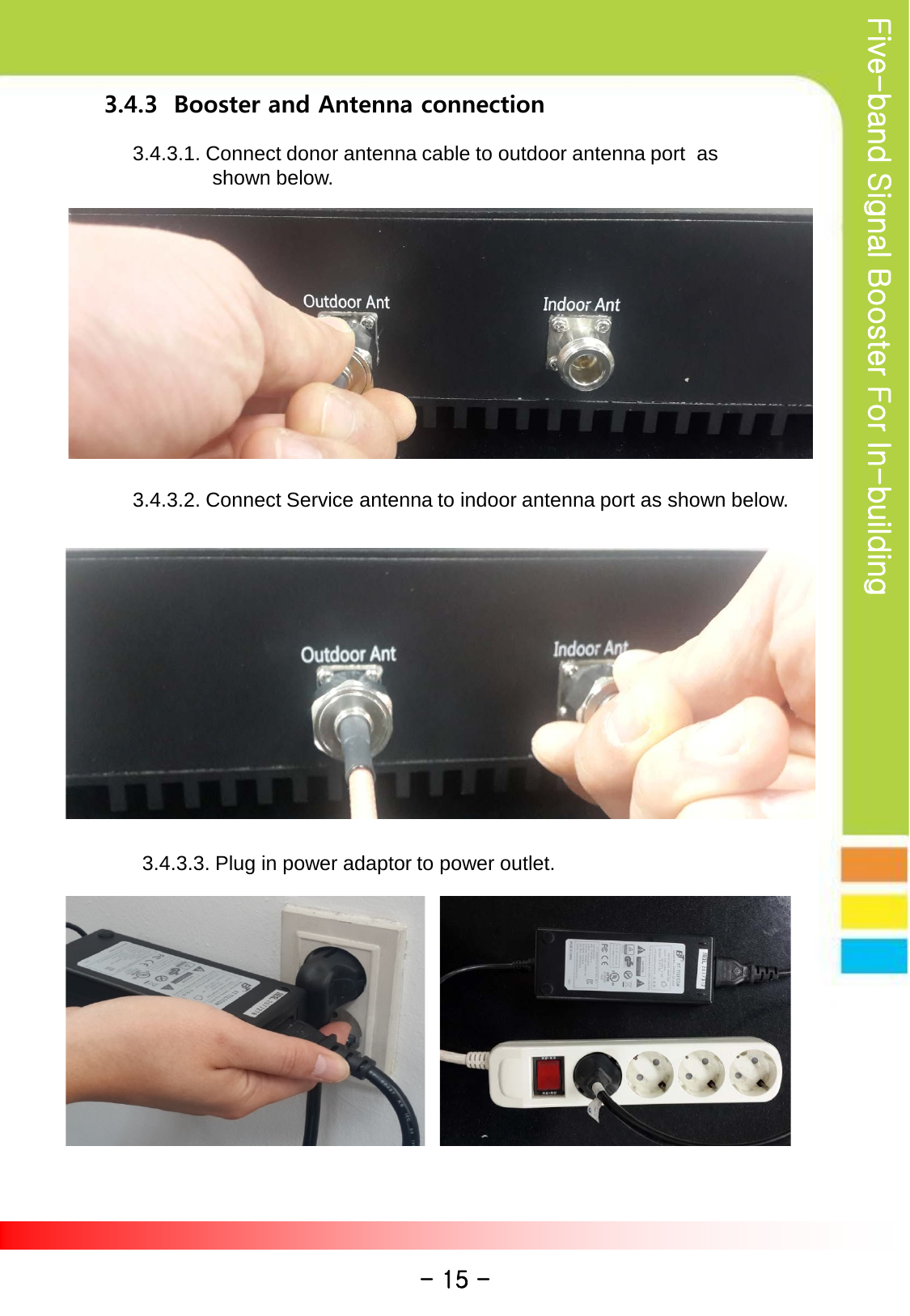
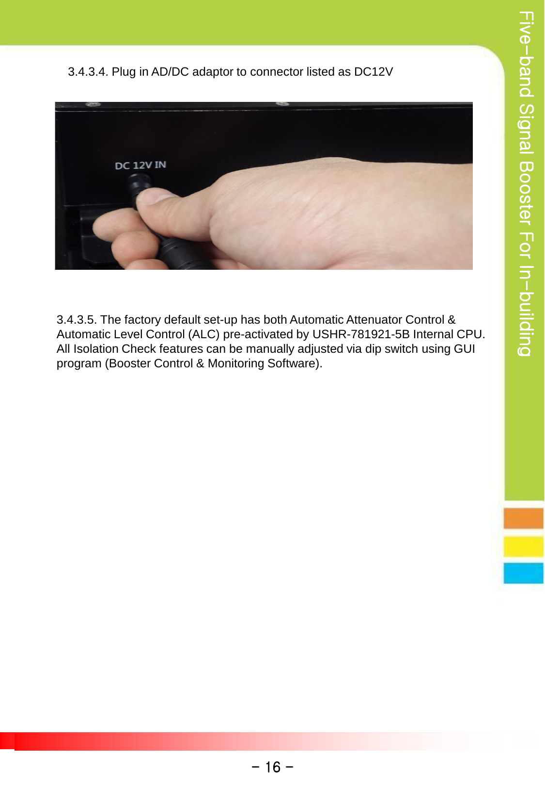
OPISYS orporated USHR-781921-5B 4G 5-Band Repeater Model Name-USHR-781921-5B User Manual revised

OPISYS Incorporated 4G 5-Band Repeater Model Name-USHR-781921-5B revised

User manual revised

Five-band Signal Booster For In-building Model : USHR-781921-5B User Guide  &  Installation Manual
Five-band Signal Booster For In-building Contents  1. Introduction 2. Kit Information 3. Installation 4. Troubleshooting 5. Specifications 6. Certificates 7. Contact Info. - 2 - Model: USHR-781921-5B  Leading Edge Technology Signal Booster    USHR-781921-5B signal booster designed to boosts cellular signal for area prone to weak coverage area. Its coverage is on 800 MHz, 1900MHz, AWS and 4G Verizon and AT&T 700 MHz as well as 4G Sprint. To allow installer to optimize signal and gain control each frequency band, it has control knobs.
Five-band Signal Booster For In-building 1. INSTRODUCTION    1.1. Precautions                                      1.1.1  Do not drop the device                   - It may damage the product and its function       1.1.2  Do not place near magnetic material                  - It may cause possible malfunction       1.1.3  Product is recommended to be used with included AC/DC adapter                - It may cause possible malfunction       1.1.4  Install the product where it is recommended                  - It may not properly operate if it is not recommended location       1.1.5  Do not disassemble/ repair the product                  - Warranty may void once you disassemble the product.        1.1.6  Turn off the device immediately if a smoke or any strange odor is                   detected from the product.        1.1.7  Use included bolts to install on the wall.  Make sure it is safely                    installed before operation             1.1.8  Outside Antenna must be installed no longer than 32 feet(10 meter)               above ground       1.1.9  This signal boosters are designed to be operated in a                designated area in a building.    Reference : Direction/Information for the proper operation Cautions : Information for users to avoid malfunctions Warning : Instruction for users to avoid unexpected hazard - 3 -  This is a CONSUMER device. BEFORE USE, you MUST REGISTER THIS DEVICE with your wireless provider and have your provider’s consent. Most wireless providers consent  to the use of signal boosters. Some providers may not consent to the use of  this device on their network. If you are unsure, contact your provider. You MUST operate this device with approved antennas and cables as  specified by the manufacturer. Antennas MUST be installed at least 20cm (8 inches) from any person. You MUST cease operating this device immediately if requested by the FCC or a licensed wireless service provider. WARNING. E911 location information may not be provided or may be inaccurate for calls served by using this device. This is a CONSUMER device.
Five-band Signal Booster For In-building      1.2 . Summary & Features   1.2.1.  Summary        This signal booster can be installed on residential area, office, warehouse etc. .        Following is advantages of using Five-band signal booster.               This Signal booster solves coverage problems and improves connection         quality in the building. In addition, this covers LTE of Band 12, Band 13,        Cellular Band 5, AWS Band 4 and PCS Band 25 for mobile phone users.         (Please see page 20 for operating frequency in details)      1.2.2.  Features                                   I. Decrease dropped call rate II. Increase signal strength III. Improve Data  / Voice  quality IV. Prolong hand phone battery  life  V. Improve data Communication Rate         I. Wider  Coverage area - Band 12 Gain DL 60dB / UL 60dB - Band 13 Gain DL 60dB / UL 61dB - Band   5 Gain DL 62dB / UL 61dB - Band   4 Gain DL 70dB / UL 68dB - Band  25 Gain DL 69dB / UL 68dB II. ALC(Automatic output  Level Control)  -  Stabilize operation in any  radio environment III. Fulfill revised FCC rule at +23dBm output power      -  Provide  high data communication rate  IV.  Easy gain control by dip switch located on the front side of product V.  Support five band  - Enable to connect  service from multiple carrier simultaneously - Band 12/13/5/4/25 service simultaneously - Band 12/13/5/4/25 adopt independent operation algorithm - 4 -
Five-band Signal Booster For In-building VI. Check status of booster by LED indicator VII. Allow to manage and control product by GUI(Graphic User Interface)         - Please ask professional installer about GUI Program VIII.   Enable to stay connected in homes and offices         - Please ask professional installer for installation on homes &                  offices IX. Device status with LED light(see page 17) X. Automatic isolation detection and gain setting         - If the device is shut down, turn on again after turning off the            AC power. XI. Uplink sleep mode         - If no signal has been detected for 5 minutes, Uplink path will be           shut down. XII. UL/DL gain interlocking mode - 5 -
Five-band Signal Booster For In-building         1.3  Functions          I. Automatic Shut Down Mode        Built-In Automatic Self-Monitoring Features for Anti-Oscillation:   Automatic shut down mode operates when oscillation in the uplink and downlinks bands are detected and terminates potential harmful interference to wireless networks. • 1 minute non-operative mode on the first initial oscillation detection. • Default algorithm re-set mode as Auto S/D Mode is cleared • Complete shut off mode on the 5th repetition of auto shutdown mode status. All path are independently monitored and operated.        II. Intermodulation Gain & Power Limit Control  Uplink & downlink path formulates consistent link balance to regulate its input and output gain & power limits.                          Max UL gain  <  - 34dB – RSSI  + MSCL  (“ FCC 13-21,(i), 78p”)                  RSSI  : Downlink composite received signal power at the  donor port                  ( calculation value : DL Output – DL Gain )                              MSCL : Mobile station and repeater service port minimum coupling Loss                  ( setting value )          All path gain limits are independently controlled  III. ALC (Automatic Level Control) & AGC       ALC is implemented to keep regular output power level for abnormal high input         signal level.         The regular output power makes possible high quality of phone call and data        transfer.        AGC is designed to automatically control gain.   •Optimal Window Size (frequency range) sets the optimal level to increase faster response to modulated signal level changes on the basis of gain power control via signal input/output differential calculation all path gain limits are independently controlled  IV. UL Path Automatic Sleep Mode       If coverage is non-existent (Zero Area Zone), Uplink path shuts off as a harmful interference avoidance protocol and minimizes its power consumption.          - 6 -
Five-band Signal Booster For In-building           IV. UL Path Automatic Sleep Mode (continue ) •  Automatic Turn Off / if UL PATH <  -90dBm •  Automatic Turn On / if UL PATH >  -88dBm             **All path gain limits are independently controlled  V. Oscillation Auto Prevention •  Degradation Protection: Detects potential performance degradation       due to the overload signal feedback (over-heating) signals by isolation     check & gain configuration. •  Feedback Limits: Sets the operating range to exceeding high level     signals from donor antenna (outside antenna) of a signal booster to     service antenna (inside antenna)                 Booster Gain  <  Antenna to Antenna Isolation – 15dB                     If optimal isolation gain is not attained, Relevant path shuts off                automatically.                      **All bands are independently controlled    - 7 -
Five-band Signal Booster For In-building ① USHR-781921-5B ② AC/DC Adapter ③ User Guide 2. Kit Information ④  Installation bolts  ① USHR-781921-5B : 5 Band BTS and mobile phone signal booster ② AC/DC Adaptor : 110VAC power supply ③ User Guide : Operation & Installation manual ④ Installation Bolts : Holds signal booster on the vertical wall  ● List of approved antennas & cables      Antenna RF Cable Item Model Gain Model Cable type Service Antenna (Indoor Antenna) TS260771  +8dBi AC200000 LMR200 TS250374  +5dBi TS320000 RF240 TQI-700/2700-SJ-01 +2dBi TS340000 RF400 Donor Antenna (Outdoor Antenna) TS210471  +4.5dBi TS350000  ½” TS220971  +9dBi TS360000  ½” TDI-690/2500-SJ +7dBi  -  - - 8 -
Five-band Signal Booster For In-building 3.1.1. Install outdoor antenna on higher location to avoid any signal interference.          Mount towards to the BTS where a clear line-of-sight  path exists for optimal         signal level.  3.1.2. Install indoor antenna at appropriate location such as wall or  roof ceiling.        Make sure service antenna is not blocked by furniture or appliances.  3.1.3. Use enclosed bolt to fix a booster on the wall and plug in power adaptor.  3.1.4. For best optimal operation, antenna isolation (oscillation level) should be                  set above minimum 15 dB gain. The industry standard for antenna to antenna         isolation formula is BDA gain + 15 dB. 3. Installation  3.1 Installation Diagram      USHR-781921-5B - 9 - Indoor AntennaOut Door AntennaBase satation
Five-band Signal Booster For In-building    3.2 One Outdoor Antenna & One Indoor Antenna Installation     Item  Model  Q’ty Instruction Outdoor Antenna TS220971  1  Install toward to cell tower Waterproof connectors connection Indoor Antenna TS260771  1  Install indoor antenna opposite direction to outdoor antenna Signal Booster USHR-781921-5B  1  Install on hard wall with bracket and screws  Outdoor Cable TS350000  1  Fasten  connection between antenna and cable connector Indoor Cable TS320000  1  Fasten  connection between antenna and cable connector AC/DC Adaptor SAMA-02-600  1  Use only provided adaptor - 10 - Cable
Five-band Signal Booster For In-building  3.3 One Outdoor Antenna & Two and More Indoor        Antenna Installation     Item  Model  Q’ty Instruction Outdoor Antenna TS220971  1  Install toward to cell tower Waterproof connectors connection Indoor Antenna TQI-700/2700-SJ-01 2(N) Install indoor antenna opposite direction to outdoor antenna N-way Splitter Option  1 Divide two antennas and fasten connection between antenna and splitter Signal Booster USHR-781921-5B  1  Install on hard wall with bracket and screws  Outdoor Cable TS360000  1  Fasten connection between antenna and cable connector Indoor Cable TS340000 3(N+1) Fasten connection between antenna and cable connector AC/DC Adaptor SAWA-02-600  1  Use only provided adaptor - 11 - Cable
Five-band Signal Booster For In-building    3.4  Installation Details 3.4.1 Outdoor Antenna Installation the antenna for the device must be installed to comply with the 10 meter above ground maximum antenna height limitation .  a) Choose a location to installation where minimum heat and good ventilation area.   b) Install outdoor antenna toward Cell Tower on the roof of building or high area where signal reception is optimized. c)  If you don’t know where a cell tower is, install the system and find      strongest direction with your cellular phone signal and then adjust      outdoor antenna. d) Run the cable to signal booster and connect to outdoor antenna. e) Run the cable to indoor antenna to signal booster and choose a location for indoor antenna. f) Use the bracket to attach to a firm wall. A minimum distance from indoor to outdoor antenna must be at least 20 vertical feet and 50 horizontal feet each other.  g) Turn on power as all connections are tightly finished. h) As the green light are on, you will get better signal.  - 12 -
Five-band Signal Booster For In-building 3.4.2  Booster Installation Item  Q’ty Instruction Indoor ANT Port  N-Type  1  Indoor antenna  connector Outdoor ANT Port  N-Type  1  Outdoor antenna connector Bracket 4 Hole  2  Use for wall mount with 4 screws Adaptor  DC IN  -  1  Adaptor for DC connection Plug in after all connection is finished LED Tri-color  5  See  page 17  GUI Port  -  1  Graphic user interface(Professional use only) Debug Port  -  1  Professional use only  - 13 -
Five-band Signal Booster For In-building ① This booster designed to automatic installation function and you may      only follow instruction manual.  ② Dip switch control refers the following table. In order to use dip       switch, the dip switch control function must be enabled by useing GUI        in advance. The default setting of dip switch is OFF. ③ Dip switch must be managed and operated by professional an installer      only. Please ask professional installers, distributors and dealers to      adjust dip switch.  - 14 - Attenuation State SW1 SW2 SW4 SW8 SW16 1 dB  ↑ ↓ ↓ ↓ ↓ 2 dB  ↓ ↑ ↓ ↓ ↓ 4 dB  ↓ ↓ ↑ ↓ ↓ 8 dB  ↓ ↓ ↓ ↑ ↓ 16 dB  ↓ ↓ ↓ ↓ ↑ ※ Switch setting is cumulative. This means the total amount of attenuation.
Five-band Signal Booster For In-building 3.4.3  Booster and Antenna connection 3.4.3.1. Connect donor antenna cable to outdoor antenna port  as               shown below. 3.4.3.2. Connect Service antenna to indoor antenna port as shown below. 3.4.3.3. Plug in power adaptor to power outlet. - 15 -
Five-band Signal Booster For In-building 3.4.3.4. Plug in AD/DC adaptor to connector listed as DC12V 3.4.3.5. The factory default set-up has both Automatic Attenuator Control &   Automatic Level Control (ALC) pre-activated by USHR-781921-5B Internal CPU.  All Isolation Check features can be manually adjusted via dip switch using GUI program (Booster Control & Monitoring Software). - 16 -
Five-band Signal Booster For In-building 4. Trouble Shooting 4.1.1.  Power on /off status. 4.1.2.  Normal operation condition. 4.1.3.  Booster detects excessive input signal and shut down. 4.1.4   Shutdown Algorithm status on High input Signal. 4.1.5.  Path OFF indicator during Uplink Sleep Mode. 4.1.6.  Isolation Shutdown Algorithm status 4.1.7.  Booster detects Insufficient Isolation between donor & service antenna           and shut down.  Item GREEN LED RED LED Reference PWR ON × See 4.1.1 OFF × See 4.1.1 ALL Band ON -  See 4.1.2 -  ON See 4.1.3 Green Blinking per 1 sec cycle -  See 4.1.4 Green Blinking per 5 sec cycle -  See 4.1.5 -  RED Blinking per 1 sec cycle See 4.1.6 RED Blinking per 5 sec cycle See 4.1.7 - 17 -
Five-band Signal Booster For In-building 5. Specifications 5.1. Electrical Specifications Item Specifications Note Frequency Range Up Link 698 ~ 716 MHz BAND12 Down Link 728 MHz ~ 757MHz BAND12 / BAND13 Up Link 776 ~ 787 MHz BAND 13 Down Link 869~894 MHz BAND 5 Up Link 824 ~849 MHz Down Link 2,110 ~ 2,155 MHz BAND 4 Up Link 1,710 ~ 1,755 MHz Down Link 1,930 ~ 1,995 MHz BAND 25 Up Link 1,850 ~ 1,915 MHz Modulation Type GSM. EDGE, CDMA, EVDO, HSPA, LTE    Input Power limit Down Link  -40dBm max BAND12 Up Link  -10dBm max Down Link  -40dBm max BAND13 Up Link  -10dBm max Down Link  -40dBm max BAND 5 Up Link  -10dBm max Down Link  -40dBm max BAND 4 Up Link  -17dBm max Down Link  -40dBm max BAND 25 Up Link  -17dBm max Output Power Down Link +2dBm@ booster output port ALL DL Channel Up Link +23dBm@ booster output port ALL UL Channel Gain(RSSI) Up Link 30dB ~ 60dB (±1.0dB) BAND 12 Down Link 42dB ~ 60dB (±1.0dB) BAND 12 / BAND 13 Up Link 31dB ~ 61dB (±1.0dB) BAND 13 Down Link 42dB ~ 62dB (±1.0dB) BAND 5 Up Link 31dB ~ 61dB (±1.0dB) Down Link 42dB ~ 70dB (±1.0dB) BAND 4 Up Link 38dB ~ 68dB (±1.0dB) Down Link 42dB ~ 69dB (±1.0dB) BAND 25 Up Link 38dB ~ 68dB (±1.0dB) Gain(ALC)` Up Link 33dB ~ 60dB (±1.0dB) BAND 12 Down Link 42dB ~ 60dB (±1.0dB) BAND 12 / BAND 13 Up Link 33dB ~ 61dB (±1.0dB) BAND 13 Down Link 42dB ~ 62dB (±1.0dB) BAND 5 Up Link 33dB ~ 61dB (±1.0dB) Down Link 42dB ~ 70dB (±1.0dB) BAND 4 Up Link 40dB ~ 68dB (±1.0dB) Down Link 42dB ~ 69dB (±1.0dB) BAND 25 Up Link 40dB ~ 68dB (±1.0dB) - 18 -
Five-band Signal Booster For In-building Item  Specifications NOTE Ripple Down / Up Link <8dB / < 8dB(Peak to Peak)   Noise Figure Down / Up Link < 8.0dB / < 8.0dB ALL BAND Max Gain Noise Power Limit Down Link < -70dBm/MHz On shutdown Up Link < -70dBm/MHz On shutdown & sleep mode Down / Up Link FCC ALL BAND Down / Up Link FCC ALL BAND Propagation Delay < 3us   Input VSWR ≤ 2.0 : 1   ALC Setting Level Down Link(Upper Value) +2dBm±1.0dB   Window Size(Lower Offset) 1 ~ 10dB(Default : 2dB) Up Link (Upper Value) +23dBm±1.0dB Window Size(Lower Offset) 1 ~ 10dB(Default : 2dB) ALC Range Down / Up Link DL ≤ 18dB UL ≤ 27dB Band 12 Down / Up Link DL ≤ 18dB UL ≤ 28dB BAND 13 Down / Up Link DL ≤ 20dB UL ≤ 28dB BAND 5 Down / Up Link DL ≤ 28dB UL ≤ 28dB BAND 4 Down / Up Link DL ≤ 27dB UL ≤ 28dB BAND 25 Shutdown Level Down Link ≥-40dBm/Total±1.0dB ALL Down Link  Up Link ≥-10dBm/Total±1.0dB Band12, Band13, Band 5 Up Link ≥-17dBm/Total±1.0dB Band 4, Band 25 OSC Level Down Link DL detects OSC under 1 sec.   Up Link UL detects OSC under 0.3 sec. Uplink In-activity Up link On@ > -88dBm, OFF@ < -90dBm -No uplink signal for        5 minutes Gain Control Range Dip Switch Down link 0dB ~ 30dB / 1dB Step -Be controlled GUI         or Dip Switch -Total Atten Control        Range : 0dB ~ 30dB        / 1dB Step Up link 0dB ~ 30dB / 1dB Step Gain Control Deviation < ± 1dB   EVM < 7% No Feedback Isolation checking Range 30dB ~ 75dB / BAND12 Detecting deviation: < ±2.0dB 31dB ~ 76dB / BAND13 31dB ~ 76dB / BAND 5 38dB ~ 83dB / BAND 4 38dB ~ 83dB / BAND 25 Out Band Spurious < -13dBm/1kHz RBW 9kHz ~ 150kHz < -13dBm/10kHz RBW 150kHz ~ 30MHz < -13dBm/100kHz RBW 30MHz ~ 1GHz < -13dBm/1MHz RBW 1GHz ~ 12.75GHz 3rd IMD Level < -19dBm Max Output Level Frequency Stability ≤ ±0.01ppm - 19 -
Five-band Signal Booster For In-building ITEM Specifications NOTE GUI Interface RS-232C Alarm & Status Display PWR ▪ Normal: Green ▪ Power turn off: Off Alarm ▪ Normal: Green ▪ Over Power Shutdown: RED ▪ Checking SD: Green Blinking per 1 sec cycle ▪ Checking OSC Algorithm: Red Blinking per                                      1 sec cycle ▪ Sleep Mode: Green Blinking per 5 sec cycle ▪ Isolation SD : RED Blinking per 5 sec cycle Power Consumption < 50W Operating Power AC/DC Adapter (AC110V or AC220V) RF Connector  N-type Female - 20 - ● Additional Information:      This booster is a bi-directional amplifier for the boosting of cellular phone signals      and data communication devices.      The following frequency bands and emission types are utilized. Frequency Band Band DL UL Band 12 & Band 13 728 ~ 757 MHz 698 ~ 716 MHz 776 ~ 787 MHz Band  5 869 ~ 894 MHz 824 ~ 849 MHz Band  4 2110 ~ 2155 MHz 1710 ~ 1755 MHz Band  25 1930 ~ 1995 MHz 1850 ~ 1915 MHz Emission Designators CDMA HSPA  LTE  EVDO EDGE GSM F9W F9W G7D F9W G7W GXW
Five-band Signal Booster For In-building Item Specifications Note Dimensions (L × W × H) 231mm x 288mm x 71mm Except Bracket and Connector (Tolerance ±5mm) Weight < 6.8Kg Item Specifications Note Temperature  -30 ~ 55℃ (-22 ~ 131℉) Humidity  10 ~ 95%         5.2. Mechanical Specification         5.3. Environment Specification Items Specifications Note AC input power 90VAC ~ 264VAC, 47Hz ~ 63Hz Output Voltage +12.0 VDC Current Range 6.0A ~ 0.0 A Operation Temperature  -30℃ ~ +55℃ Operation humidity  10% ~ 90%         5.4. AC/DC Adaptor Specification 6. Certificates - 21 -
Five-band Signal Booster For In-building 7. Contact Information         7.1  Location                      7.2 Contact     Address : 511 s. HARBOR BLVD STEP. LAHABRA, CA 90631   Mon.-Fri. Hours : 9 a.m. to 5 p.m.      TEL : 562-448-3102     FAX : 562-448-3105 - 22 -
Five-band Signal Booster For In-building - 23 - Memo

Navigation menu