OPTOELECTRONICS OPI3301 Wireless Handheld 2D Scanner User Manual SS11012 OPI 3301 ENG1
OPTOELECTRONICS Co., Ltd. Wireless Handheld 2D Scanner SS11012 OPI 3301 ENG1
UserManual.wiki
>
OPTOELECTRONICS
>
OPI3301 User Manual
manual
Navigation menu
Upload a User Manual
Namespaces
Wiki Guide
HTML
PDF
Info
Views
User Manual
Discussion / Help
Navigation

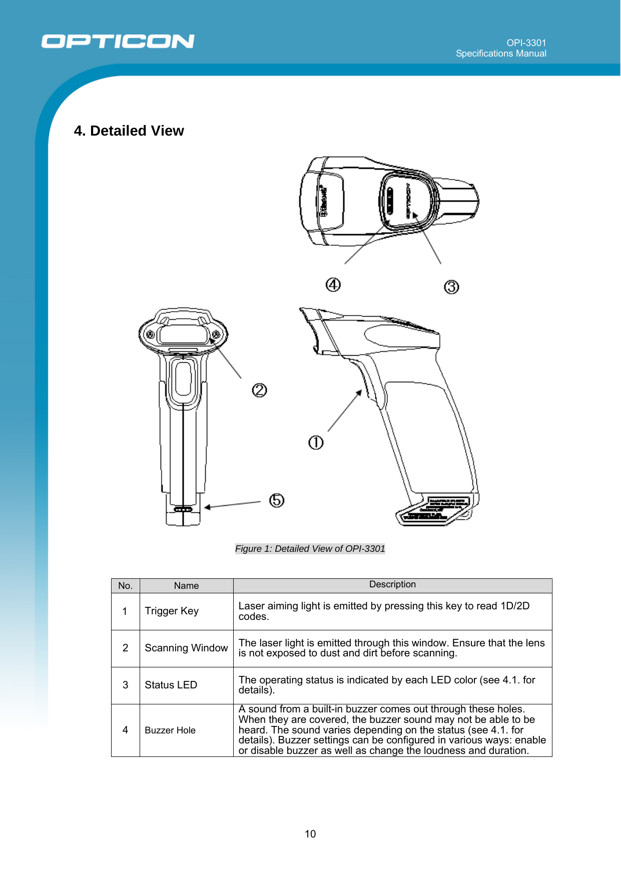
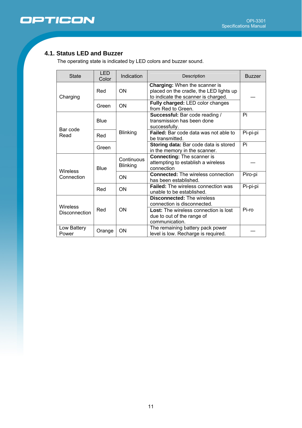
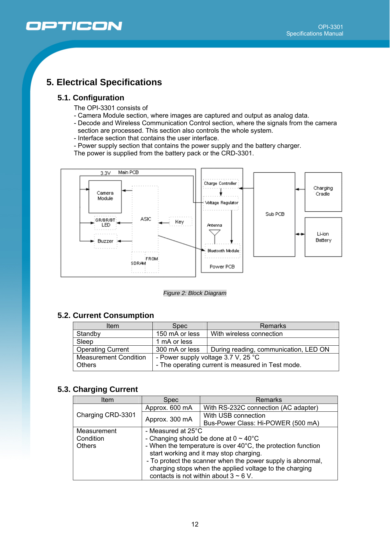
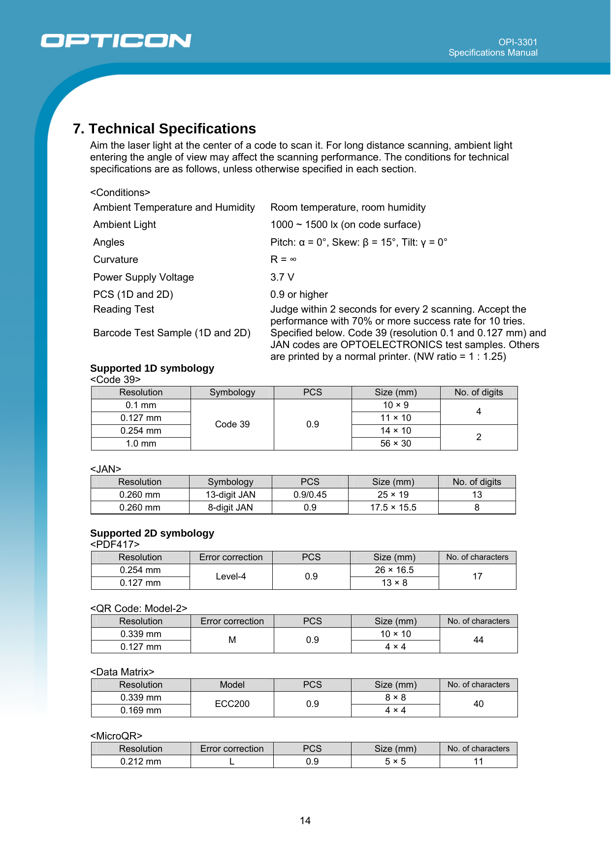
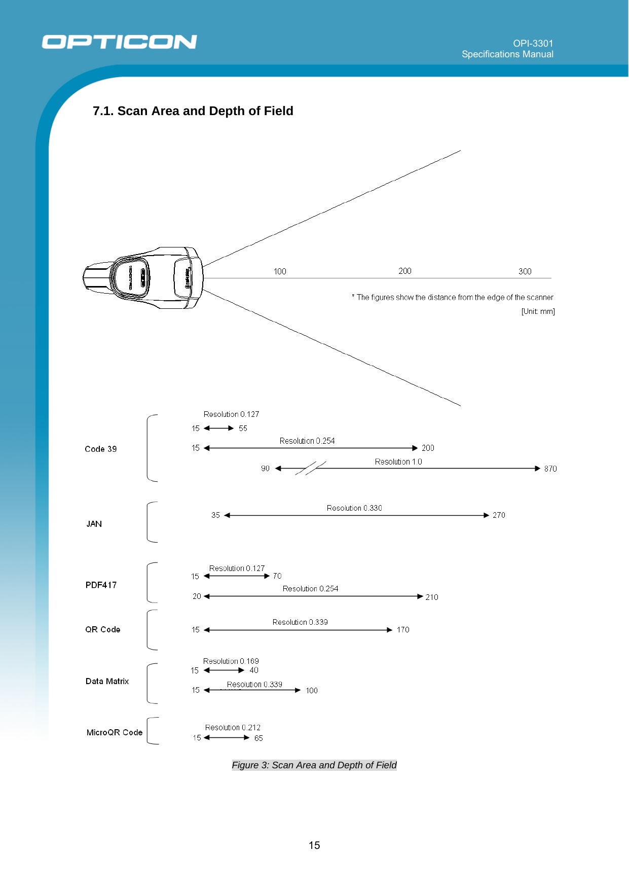
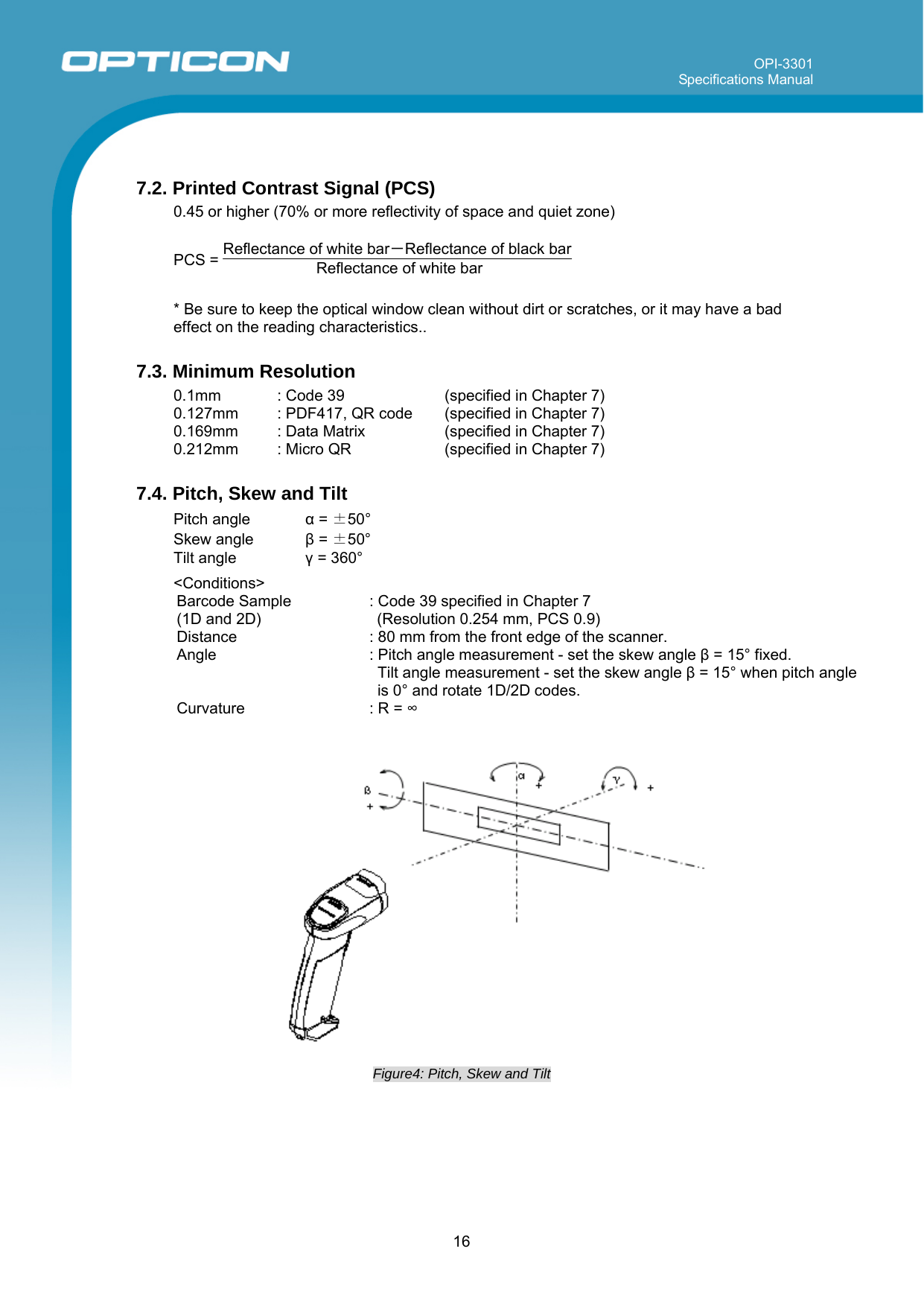
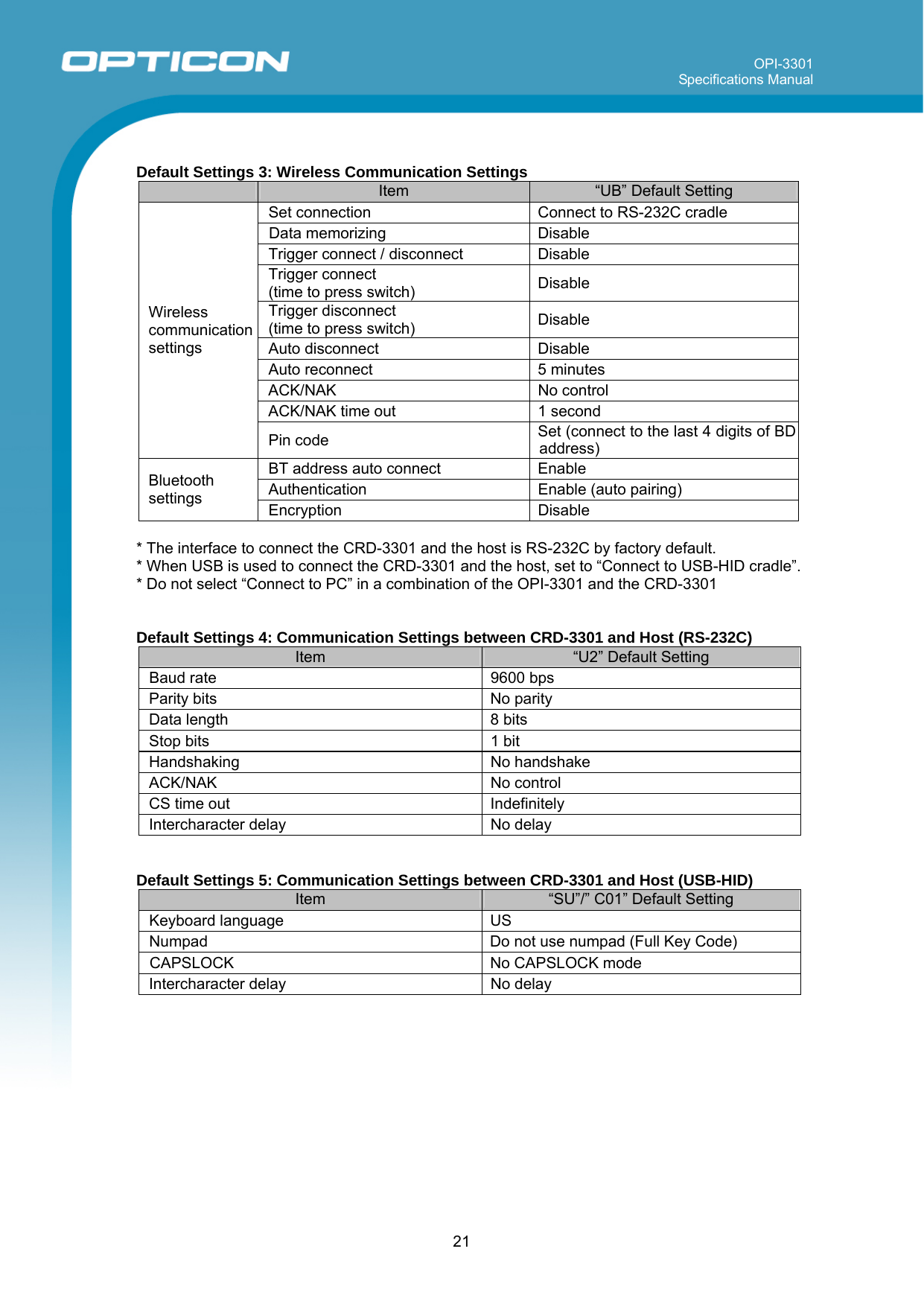
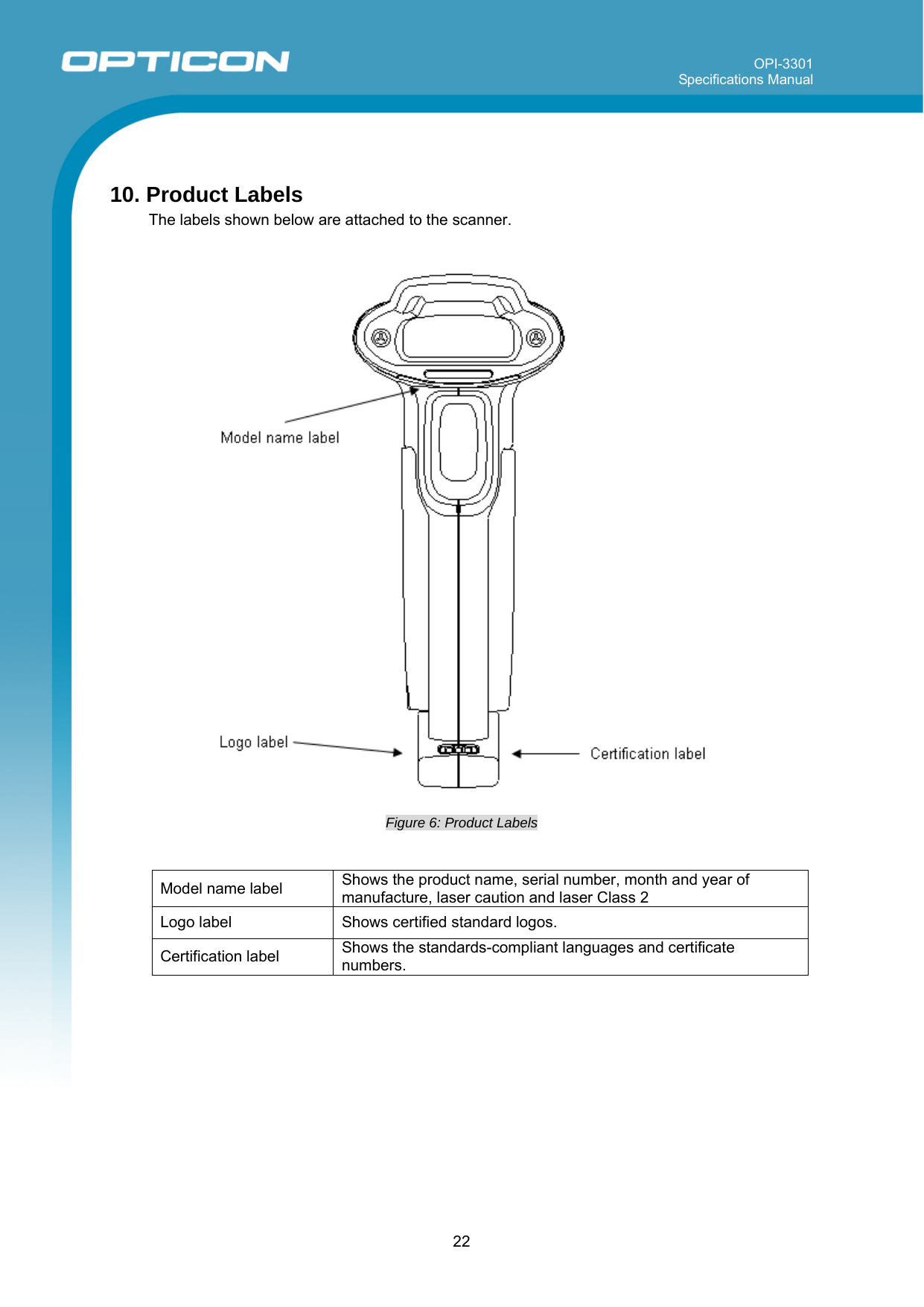
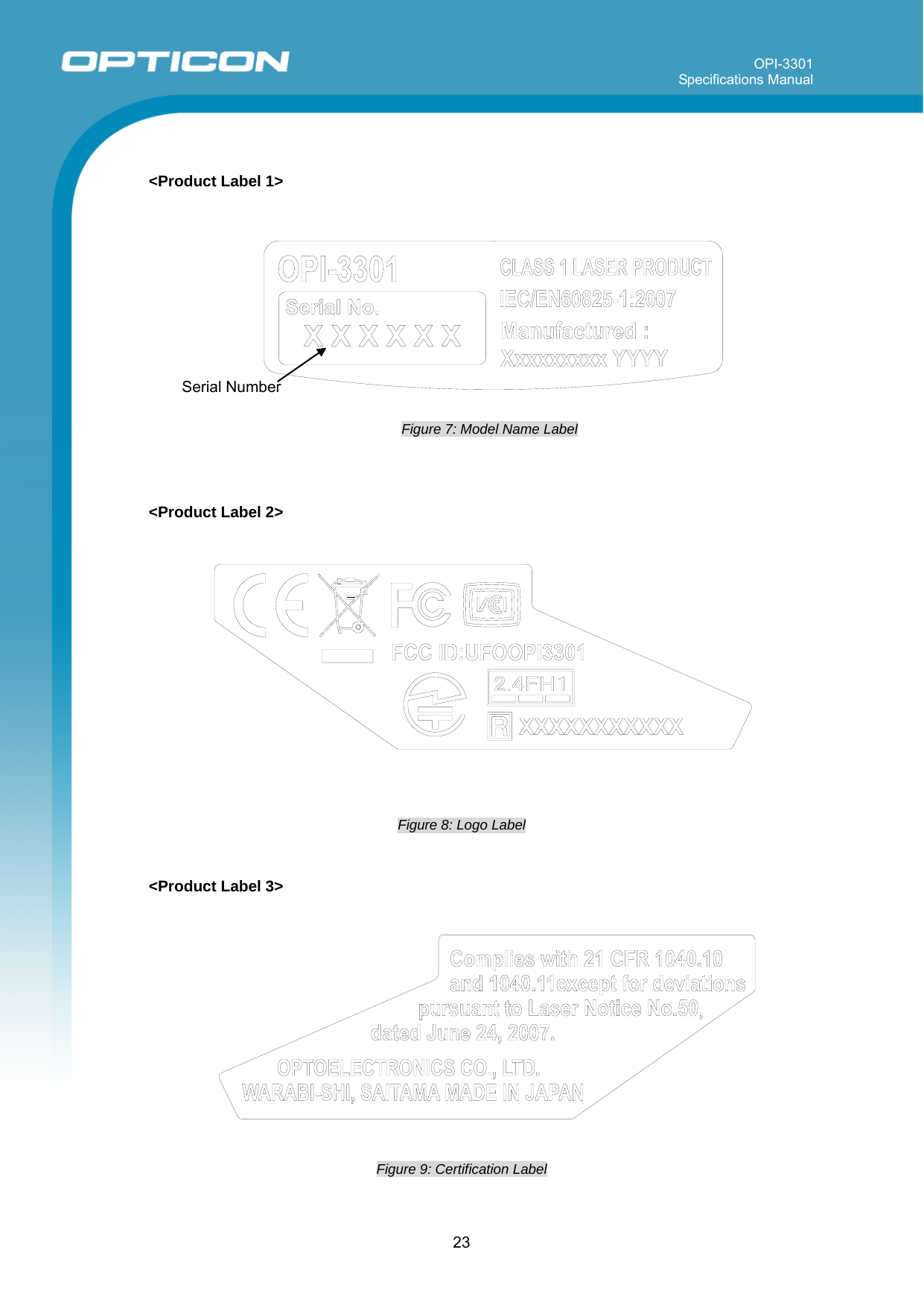
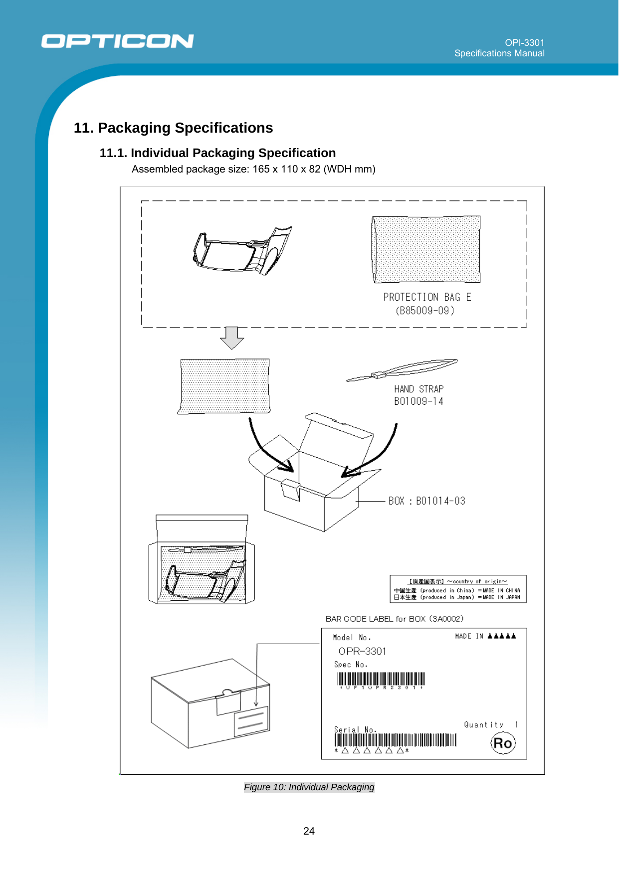
![OPI-3301 Specifications Manual 20 Code type ReadTransmit Code LengthTransmitCD CalculateCD Transmit Other Set Prefix Set SuffixGS1 DataBar Omnidirectional GS1 DataBar Truncated GS1 DataBar Stacked GS1 DataBar Stacked Omnidirectional ○ × ○ ○ - CR GS1 DataBar Limited ○ × ○ ○ - CR GS1 DataBar Expanded GS1 DataBar Expanded Stacked ○ × - ○ - CR Composite EAN EAN-13 CCA EAN-13 CCB EAN-8 CCA EAN-8 CCB × × ○ (1D code) ○ - CR Composite UPC UPC-A CCA UPC-A CCB UPC-E CCA UPC-E CCB × × ○ (1D code) ○ - CR Composite GS1 DataBar CCA CCB Limited CCA Limited CCB Expanded CCA Expanded CCB × × ○ (1D code) ○ - CR Composite GS1-128 CCA CCB CCC × × - ○ - CR GS1 DataBar and GS1-128 are formerly called RSS and UCC/EAN-128 respectively. Notes: (1) “Reading” column ○ : Enable reading, × : Disable reading. (2) “Transmit code length” column ○ : Transmit code length” , × : Do not transmit code length , - : Not supported. (3) “Transmit CD” column ○ : Transmit check digit , × : Do not send check digit. (4) “Calculate CD” column ○ : Calculate check digit, × : Do not calculate check digit. (5) “Prefix” column - : No prefix setting (6) For USB setting, the suffix setting is “Enter [0x84]” (Direct input keyboard keys menu “7I”.) Default Settings 2: Wireless Communication Settings Item Default setting Setting the number of characters Fixed length OFF all codes Read mode Single read Multiple read (code only) Disable Multiple row read Disable Trigger switch Enable Read time 2 seconds Buzzer duration 50 ms Buzzer tone 3 kHz Buzzer loudness Volume 1 (max) Indicator LED duration 200 ms](https://usermanual.wiki/OPTOELECTRONICS/OPI3301/User-Guide-1494338-Page-20.png)