OPTOELECTRONICS OPI4012 Bluetooth handy Image scanner User Manual manual
OPTOELECTRONICS Co., Ltd. Bluetooth handy Image scanner manual
UserManual.wiki
>
OPTOELECTRONICS
>
OPI4012 User Manual
manual
Navigation menu
Upload a User Manual
Namespaces
Wiki Guide
HTML
PDF
Info
Views
User Manual
Discussion / Help
Navigation
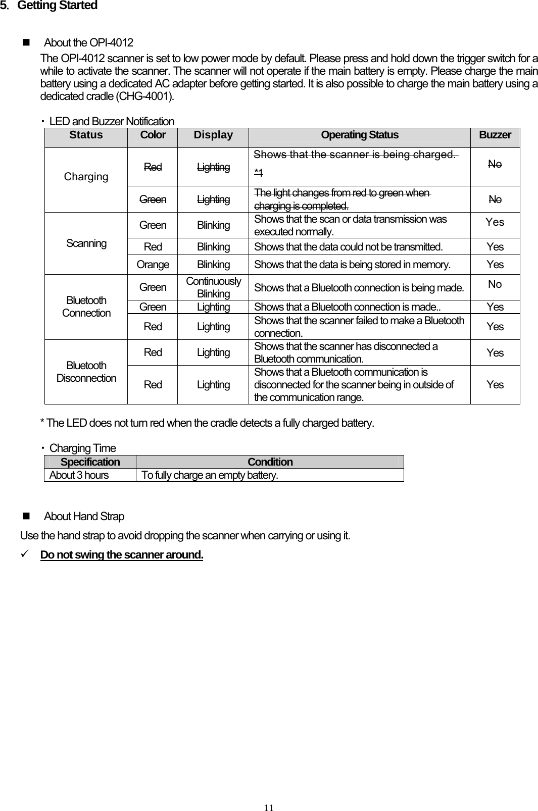
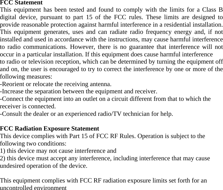
![136.Scanning Barcodes During a scan, the green LED patterns shown below will be visible. These patterns assist you in aiming the scanner; they are superimposed on the illuminated scan field. The aiming patterns are only a guide. They do not indicate exact scannable width or distance between a scanner and a barcode. How to use the aiming guide • The focal point is where two central LED light patterns (green and square-shaped) overlap—where two dots meet. • To scan a barcode within the aiming range, make sure that two central LED light patterns overlap, then place the center of the overlapping LED light patterns on the center of the barcode. • To scan a barcode wider than a width of the aiming range, aim at the barcode from further away. Make sure that the barcode is between two LED light patterns on both the right and left. 9 Scanning performance may decline due to the specular reflection when the symbology is printed on certain types of materials. In such cases, incline the scanner at 15 degrees to adjust the scanning angle. Distance from a Mask of a Camera 3080130180[in the millimeters]Horizontal Direction](https://usermanual.wiki/OPTOELECTRONICS/OPI4012/User-Guide-1010773-Page-14.png)
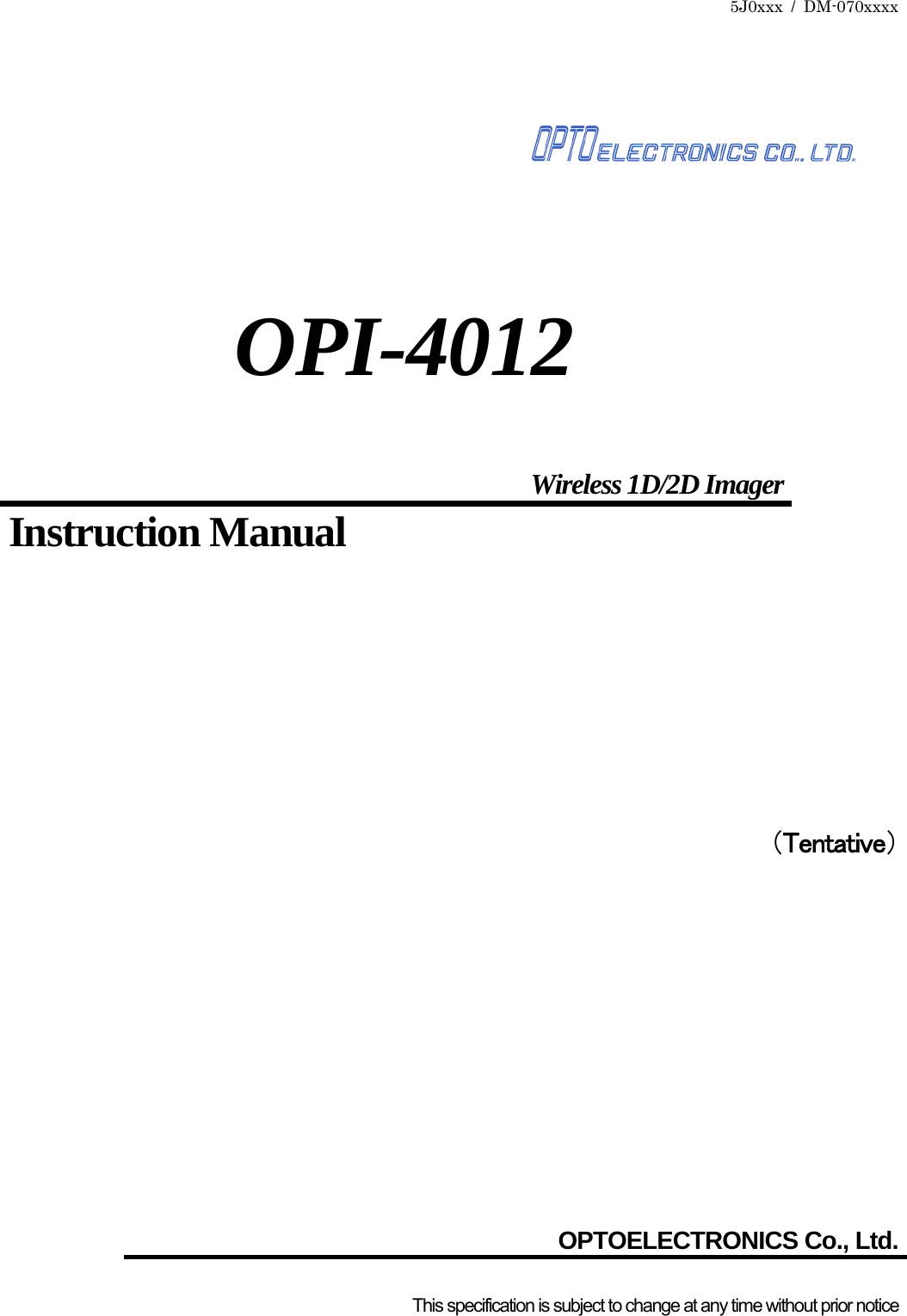
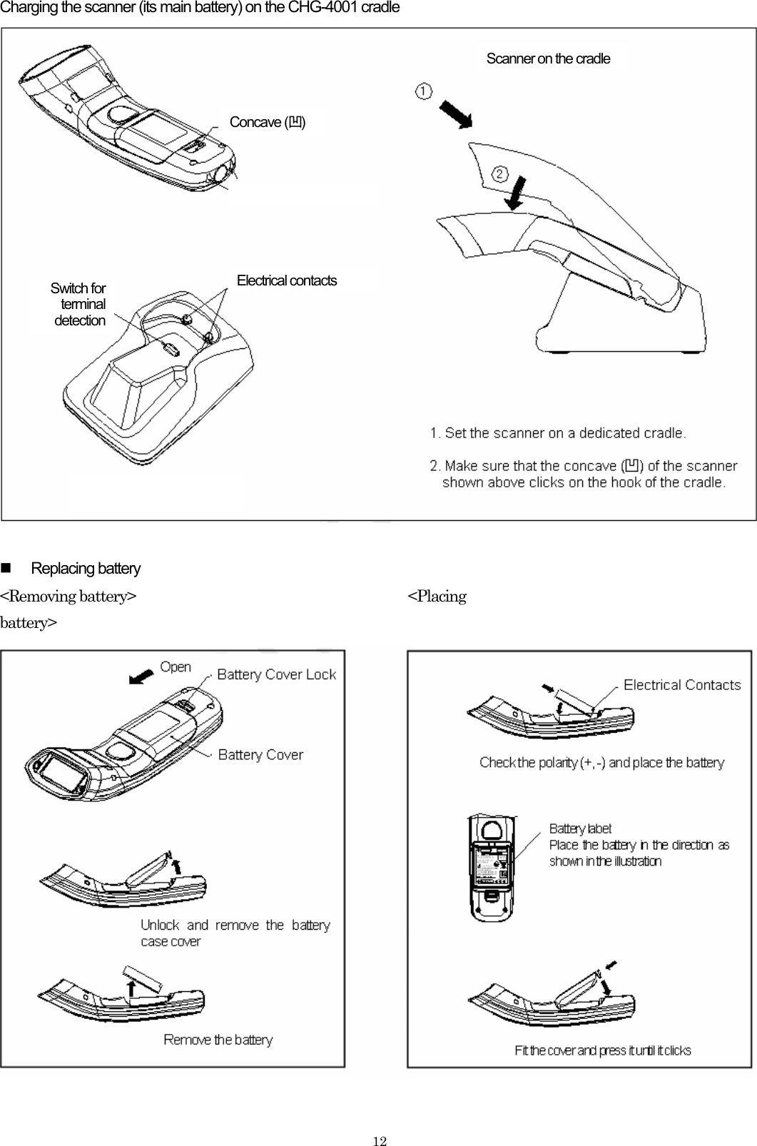
![16■ Handshaking Settings ・You can set the handshaking for the communication between the host and the scanner. ・When it is set to “No handshaking”, the reliability of the transmitted data will be lower. It is recommended to enable ACK/NAK. 9 ACK/NAK No Response 9 ACK/NAK ■ ACK/NAK Timeout Settings ・You can set the timeout for the ACK/NAK sent from the host. ■ Communication Settings ・Communication settings are set to the following by default: Bluetooth Device Address Settings: Disabled PIN Code Settings: Disabled Encryption Settings: Disabled Handshaking Settings: No Handshake ACK/NAK Timeout Settings: 100 ms ・The following communication settings can be configured using the attached menu barcode lists. Auto connect Data memorizing Trigger connection Press trigger switch time to connect Press trigger switch time to disconnect Auto disconnect Auto reconnect ■ Auto Connect ・You can set the scanner to automatically connect after setting the Bluetooth device address. ■ Data memorizing ・Scanned barcode data will be stored in a memory automatically when the data memorizing setting is enabled. ・The capacity of the memory is about 100KB. ・When the memory get full while the scanner is outside of the communication range, the scanner sounds a buzzer and you will not be able to continue the scanning operation. ・The stored data will be transmitted automatically when the scanner returns to the communication range. ・If you scan the data clear menu barcode [+-MCLR-+] or the IEEE address label while resending the stored data outside of the communication range, the stored data will be deleted. ・If you disable the data memorizing settings while the scanner is outside of the communication range, the stored data will be deleted.](https://usermanual.wiki/OPTOELECTRONICS/OPI4012/User-Guide-1010773-Page-17.png)
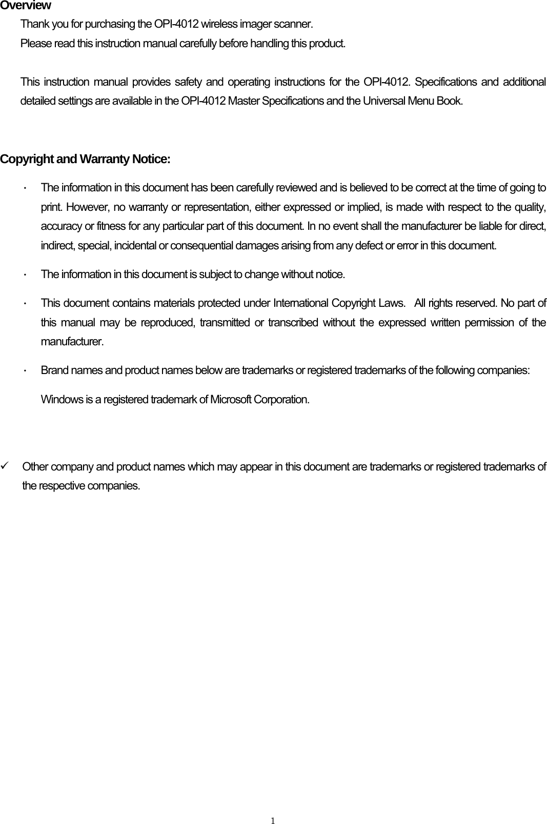
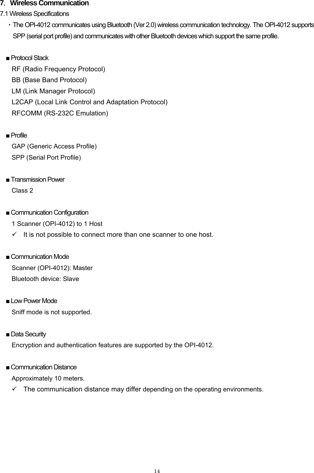
![179 The scanner will not carry out the scanning operation if the data memorizing setting is disabled. 9 Auto reconnect feature will operate in every 20 seconds. ■ Trigger Connection ・You can set the scanner to connect or disconnect by pressing down the trigger key for the set duration. ■ Press trigger switch time to connect ・This is the time the trigger switch needs to be pressed where after the scanner tries to establish a connection. ■ Press trigger switch time to disconnect ・This is the time the trigger switch needs to be pressed where after the scanner disconnects. ■ Auto disconnect ・If the scanner is idle for configured time, it will be disconnected. ■ Auto reconnect ・If the scanner is disconnected because it is out side of the communication range, the reader will try to establish connection during the configured time. ■ Default setting [S0] ・Foregoing settings are set to the following by default: Auto Connect: Enabled Data Memorizing: Enabled Trigger Connection: Disabled Press trigger switch time to connect: 3 seconds Press trigger switch time to disconnect: 5 seconds Auto disconnect: Disabled Auto reconnect: 5 minutes](https://usermanual.wiki/OPTOELECTRONICS/OPI4012/User-Guide-1010773-Page-18.png)
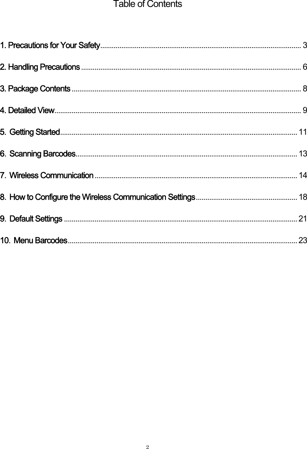
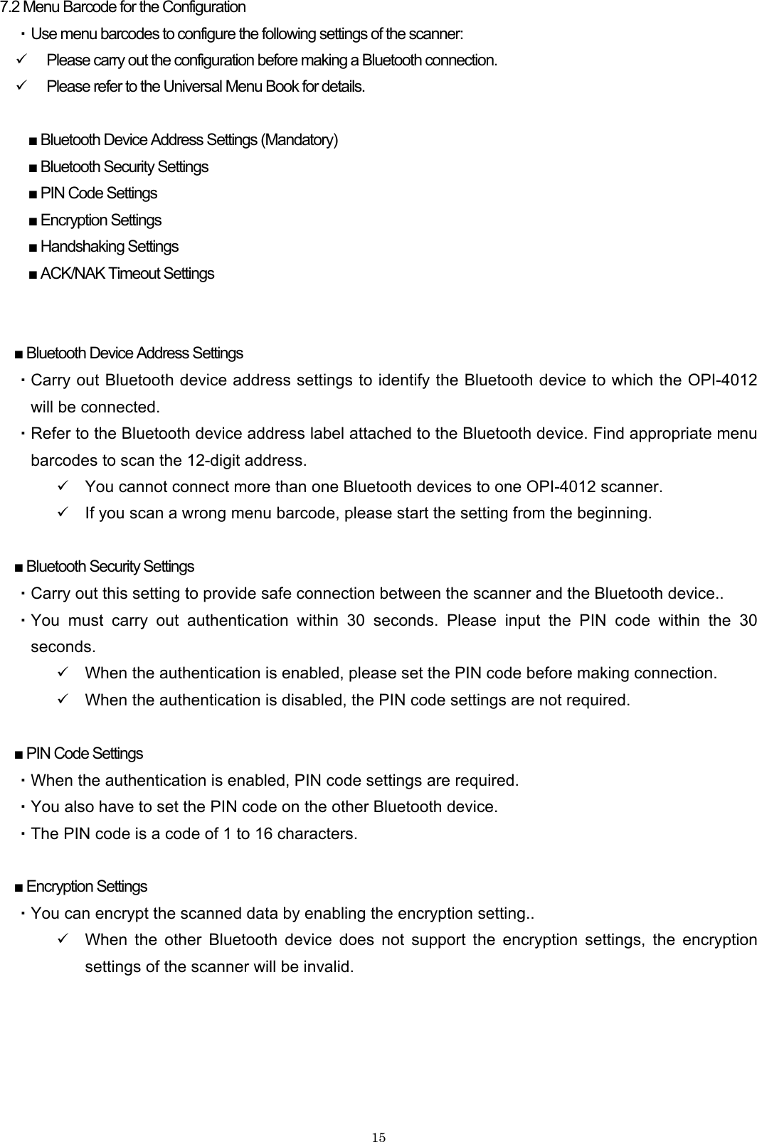
![188.How to Configure the Wireless Communication Settings 8.1 Connect without Authentication 1. Use the universal menu book to set the scanning options and read options of the scanner. ・ This operation will not be necessary if you would like to use the scanner with the default settings. 2. Use this instruction manual to set the communication settings. ・ Scan the menu barcode “Connect to PC”. (The trigger connect option will be enabled.) ・ Scan the numbers and characters of the 12-digit Bluetooth device address. 3. Establish connection with the Bluetooth device as follows: ・ Scan a 12-digit Bluetooth device address ・ Press trigger key for the set duration. ・ Scan “Manually connect” menu barcode [+-CONN-+]. 4. The LED of the scanner blinks green light and make connection. 5. Once the scanner makes connection successfully, the LED turns solid green and the scanner sounds a buzzer. ・ If the scanner fails in making connection, the LED of the scanner blinks red light and the scanner sounds a warning buzzer. * 6. You will be able to scan barcodes. 7. You can disconnect the Bluetooth communication as follows: ・ Scan “Manually disconnect” menu barcode [+-DISC-+]. ・ Press trigger key for the set duration. 8. The LED of the scanner turns solid red and the scanner sounds a warning buzzer when it disconnect Bluetooth connection. Notes: * Please make sure that the authentication is disabled. * Please confirm the Bluetooth device address.](https://usermanual.wiki/OPTOELECTRONICS/OPI4012/User-Guide-1010773-Page-19.png)
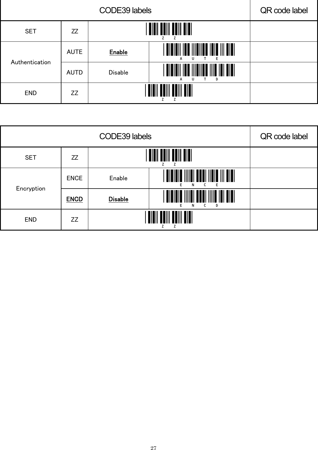
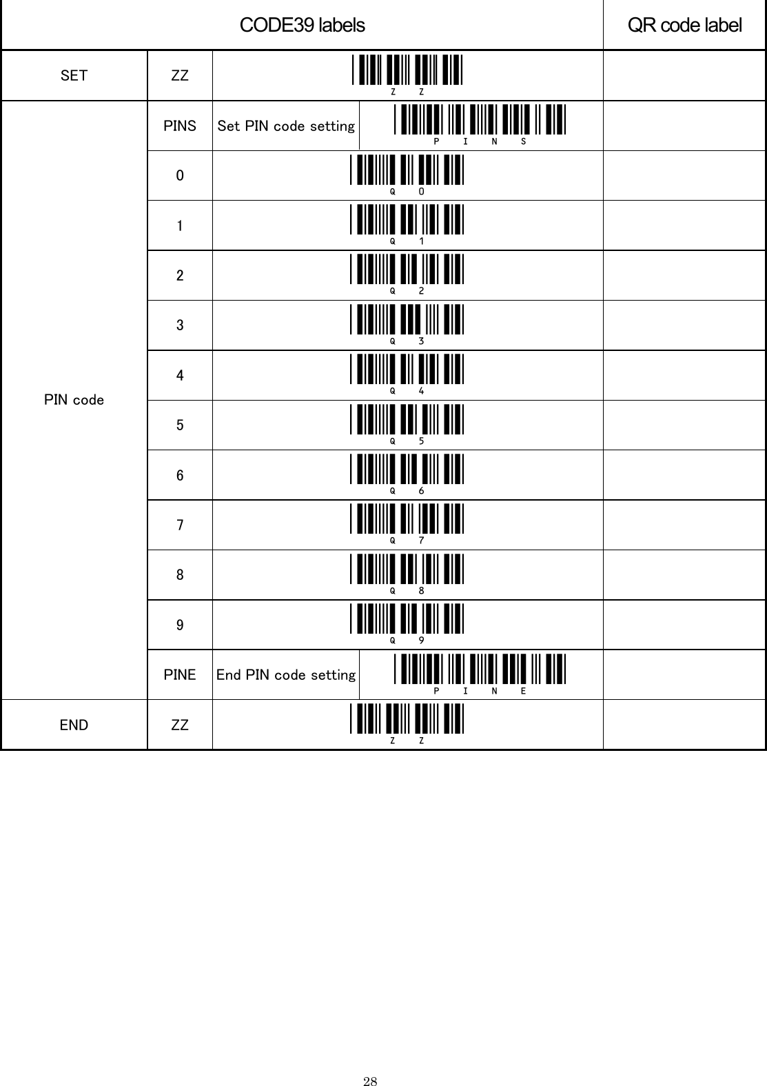
![198.2 Connect with Authentication 1. Use the universal menu book to set the scanning options and read options of the scanner. ・ This operation will not be necessary if you would like to use the scanner with the default settings. 2. Use this instruction manual to set the communication settings. ・ Scan the menu barcode “Connect to PC”. (The trigger connect option will be enabled.) ・ Scan the numbers and characters of the 12-digit Bluetooth device address using the attached list of menu barcodes. ・ Scan the menu barcode “Enable authentication”. ・ Scan the numbers of the PIN code using the attached list of menu barcodes. ・ If you desire to encrypt the scanned data, scan the menu barcode “Enable encryption”. 3. Establish connection with the Bluetooth device as follows: ・ Scan a 12-digit Bluetooth device address ・ Press trigger key for the set duration. ・ Scan “Manually connect” menu barcode [+-CONN-+]. 4. The LED of the scanner blinks green light and make connection. 5. Input the same PIN code to the Bluetooth device. 6. Once the scanner makes connection successfully, the LED turns solid green and the scanner sounds a buzzer. ・ If the scanner fails in making connection, the LED of the scanner blinks red light and the scanner sounds a warning buzzer. * 7. You will be able to scan barcodes. 8. You can disconnect the Bluetooth communication as follows: ・ Scan “Manually disconnect” menu barcode [+-DISC-+]. ・ Press trigger key for the set duration. 9. The LED of the scanner turns solid red and the scanner sounds a warning buzzer when it disconnect Bluetooth connection. Notes: * Please make sure that the authentication is disabled. * Please confirm the Bluetooth device address. * Please confirm the PIN code.](https://usermanual.wiki/OPTOELECTRONICS/OPI4012/User-Guide-1010773-Page-20.png)
![20■Notes ・ The scanner does not scan any barcodes other than menu barcodes before it is connected to the Bluetooth device. (If the [BM1] settings are configured, the scanner will scan other barcodes.) ・ If you scan a 12-digit barcode label before connecting the scanner to the Bluetooth device, the scanner will acknowledge the 12-digit barcode as a Bluetooth device address. - Before establishing Bluetooth connection: • A 12-digit barcode label with quiet zones on both ends (Code 39) Æ Acknowledged as a Bluetooth address • A 12-digit barcode label Æ Acknowledged as a Bluetooth address - After establishing Bluetooth connection: • A 12-digit barcode label with quiet zones on both ends (Code 39) Æ Acknowledged as a Bluetooth address • A 12-digit barcode label Æ Acknowledged as a barcode ・ If the battery voltage gets low, the LED lights red when scanning a barcode. Please charge the scanner. ・ When the scanner is outside of the communication range or when the Bluetooth communication is disconnected, the LED of the scanner turns solid red and the scanner sounds a buzzer. ・ When the scanner carries out a scanning operation outside of the communication range, the LED of the scanner turns orange and the buzzer sound changes. ・ When the scanner is set to “data memorizing disabled”, the scanner will not carry out scanning operation outside of the communication range. ・ When the memory of the scanner gets full while the scanner is outside of the communication range, you will not be able to continue the scanning operation. ・ The scanner tries to automatically reconnect in every 20 seconds while it is outside of the communication range. ・ When the “trigger connection option” is enabled, the scanner will stop the auto reconnect operation and establish the connection when the trigger is pressed for the set duration (press trigger switch time to connect). ・ In this case, the stored barcode data will be deleted. ・ Also, if you disable the data memorizing settings while the scanner is outside of the communication range, the stored data will be deleted. ・ If you use a trigger key to reconnect while the scanner is set to [CA00], the scanner will return to the idle mode and stored data will be deleted. To reconnect using the trigger key, do not set to [CA00] but set to [CA99] and [BM1].](https://usermanual.wiki/OPTOELECTRONICS/OPI4012/User-Guide-1010773-Page-21.png)

![26 Barcode for Bluetooth address setting 0 _Q0_ 9 _Q9_ 1 _Q1_ A _0A_ 2 _Q2_ B _0B_ 3 _Q3_ C _0C_ 4 _Q4_ D _0D_ 5 _Q5_ E _0E_ 6 _Q6_ F _0F_ 7 _Q7_ 8 _Q8_ Flow : [ZZ]⇒[BDAS]⇒[12Digit Bluetooth address]⇒[BDAE]⇒[ZZ] In case reading wrong address, restart from reading [BDAS]](https://usermanual.wiki/OPTOELECTRONICS/OPI4012/User-Guide-1010773-Page-27.png)
![29<Communication and Connection> CODE39 labels QR code label SET ZZ _ZZ_ ENAU Enable _enau_ Auto connect DIAU Disable _diau_ END ZZ _ZZ_ <Connection/Disconnection> Manually connect +-CONN-+ _+-CONN-+_ Manually disconnect +-DISC-+ _+-DISC-+_ <Default (Interface)> CODE39 labels QR code label SET ZZ _ZZ_ Default SO _SO_ END ZZ _ZZ_ ] ] OPTOELECTRONICS Co., Ltd. OPI-4012 Instruction Manual Marketing Group 12-17, Tsukagoshi 4-chome, Warabi, Saitama 335-0002 Japan TEL: +81-48-446-1183 FAX: +81-48-434-2820](https://usermanual.wiki/OPTOELECTRONICS/OPI4012/User-Guide-1010773-Page-30.png)