OPTOELECTRONICS OPR3101 Wireless Barcode Scanner User Manual UsesManual OPR31012007320
OPTOELECTRONICS Co., Ltd. Wireless Barcode Scanner UsesManual OPR31012007320
UserManual.wiki
>
OPTOELECTRONICS
>
OPR3101 User Manual
>
User manual 1
Contents
1.
User manual 1
2.
user manula 2
User manual 1
Navigation menu
Upload a User Manual
Namespaces
Wiki Guide
HTML
PDF
Info
Views
User Manual
Discussion / Help
Navigation
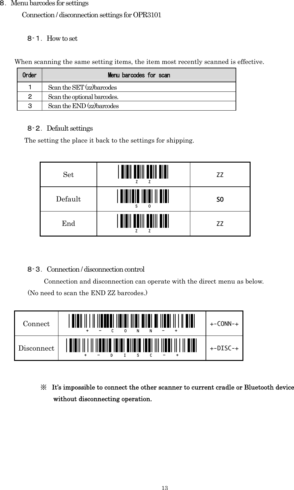
![11 ■Connecting authentication settings Settings for authentication settings Please complete to enter the pin code with 30 seconds due to the time limit of the authentication system. ※ Please set the PIN code before connecting with authentication. ※It may be a need to enter the pin code connecting with authentication. Then please enter the code again. ※You don’t need to enter the Pin code when connecting without authentications. 6.Connecting and disconnecting process 6-1.Connecting process CRD-3101 1. Connect CRD-3101 to AC adopter and eitherRS232C I/F or USB cable. 2. Make sure the power supply LED, communicating LED, and wireless LED blinking. 3. Connect the cable to the host computer. 4. Make sure the communicating LED lights of after blinking. 5. Scan the BD address label. 6. As soon as blue LED blinks, connecting starts. 7. When connecting succeed, blue LED starts to light after blinking and the buzzer sounds. ※Please let us know when connecting it to USB, adopter and other Bluetooth device so that we can offer you the BD address barcode. ※ Red LED blinks and buzzer beeps as a caution when connecting fails. 6-2.Disconnecting process 1.Disconect the communication as below. ・ Scan the label for disconnecting , [ +--DISC-+ ] 2. When disconnecting finishes, red LED lights and the buzzer beeps. ※Also you can disconnect the communication to read default setting menu Barcode [ SO] .](https://usermanual.wiki/OPTOELECTRONICS/OPR3101.User-manual-1/User-Guide-803218-Page-12.png)
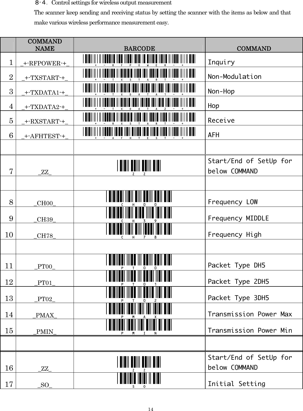
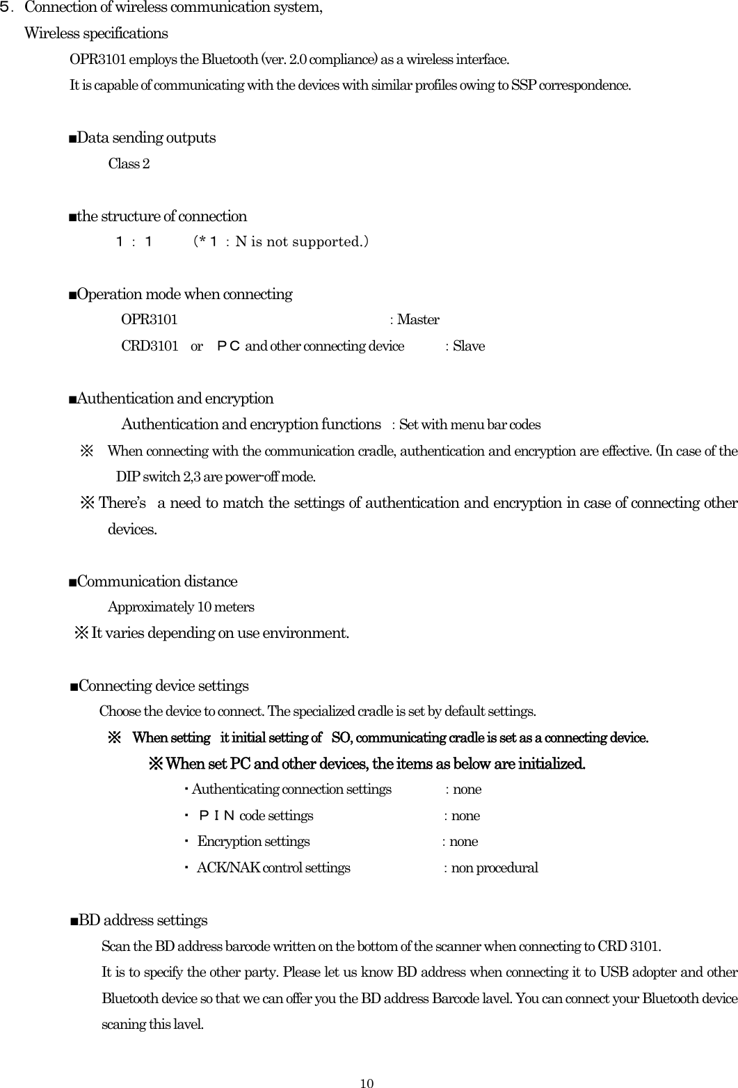
![127. Settings for shipping The menu barcodes of scanner, communication and connection make settings easy. Therefore there are menu barcodes for the default settings. Default setting <SO>menu is set before shipping. Default Setting [SO] Readable codes Code type Reading Transit and code length Transit and CD Calculate and CD Prefix settings Suffix settings Other transit items UPC-A ○ × ○ ○ - CR UPC-A Add-on × × ○ ○ - CR UPC-E ○ × ○ ○ - CR UPC-E Add-on × × ○ ○ - CR EAN-13 ○ × ○ ○ - CR EAN-13 Add-on × × ○ ○ - CR EAN-8 ○ × ○ ○ - CR EAN-8 Add-on × × ○ ○ - CR CODE-39 ○ × ○ × - CR Not transmit ST/SP CODE-39 Trioptic ○ × ○ × - CR Not transmit ST/SP NW-7(CODABAR) ○ × ○ × - CR Not transmit ST/SP Industrial2of5 ○ × ○ × - CR Interleaved2of5 ○ × ○ × - CR CODE-93 ○ × × ○ - CR CODE-128 ○ × × ○ - CR EAN-128 × × × ○ - CR S-Code ○ × ○ × - CR MSI/Plessey ○ × ○CD1 ○CD1 - CR UK/Plessey ○ × ○ ○ - CR Telepen ○ × × ○ - CR Matrix2of5 × × ○ × - CR Chinese Post Matrix 2of5 × × ○ × - CR IATA ○ × ○ × - CR RSS-14 × × ○ ○ - CR RSS-limited × × ○ ○ - CR RSS-expanded × × ○ ○ - CR PDF417 × × - - - CR MicroPDF417 × × - - - CR](https://usermanual.wiki/OPTOELECTRONICS/OPR3101.User-manual-1/User-Guide-803218-Page-13.png)