ORBCOMM License OGI100 Mobile Satellite Earth Station Modem User Manual
ORBCOMM License Corp. Mobile Satellite Earth Station Modem Users Manual
UserManual.wiki
>
ORBCOMM License
>
OGI100 User Manual
Users Manual
Navigation menu
Upload a User Manual
Namespaces
Wiki Guide
HTML
PDF
Info
Views
User Manual
Discussion / Help
Navigation
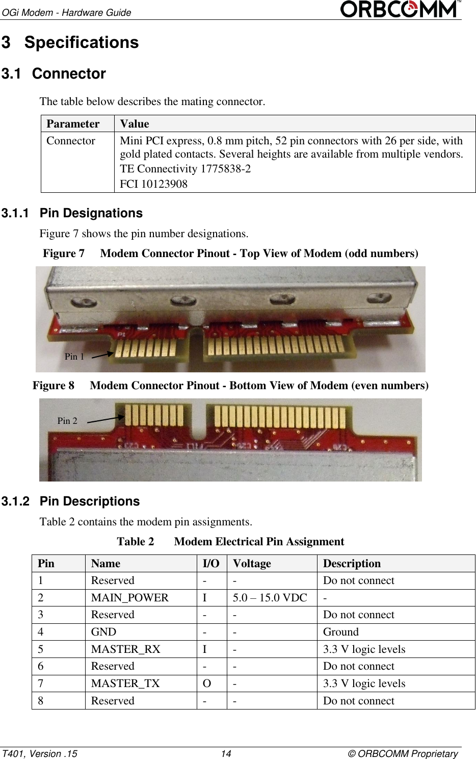
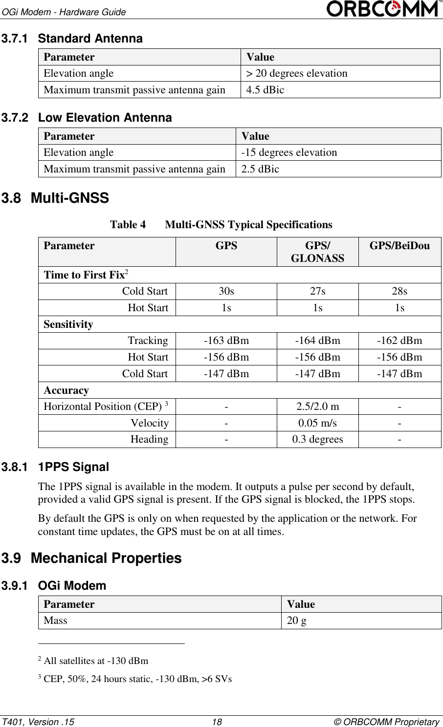
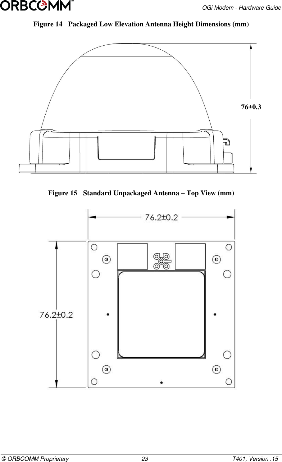
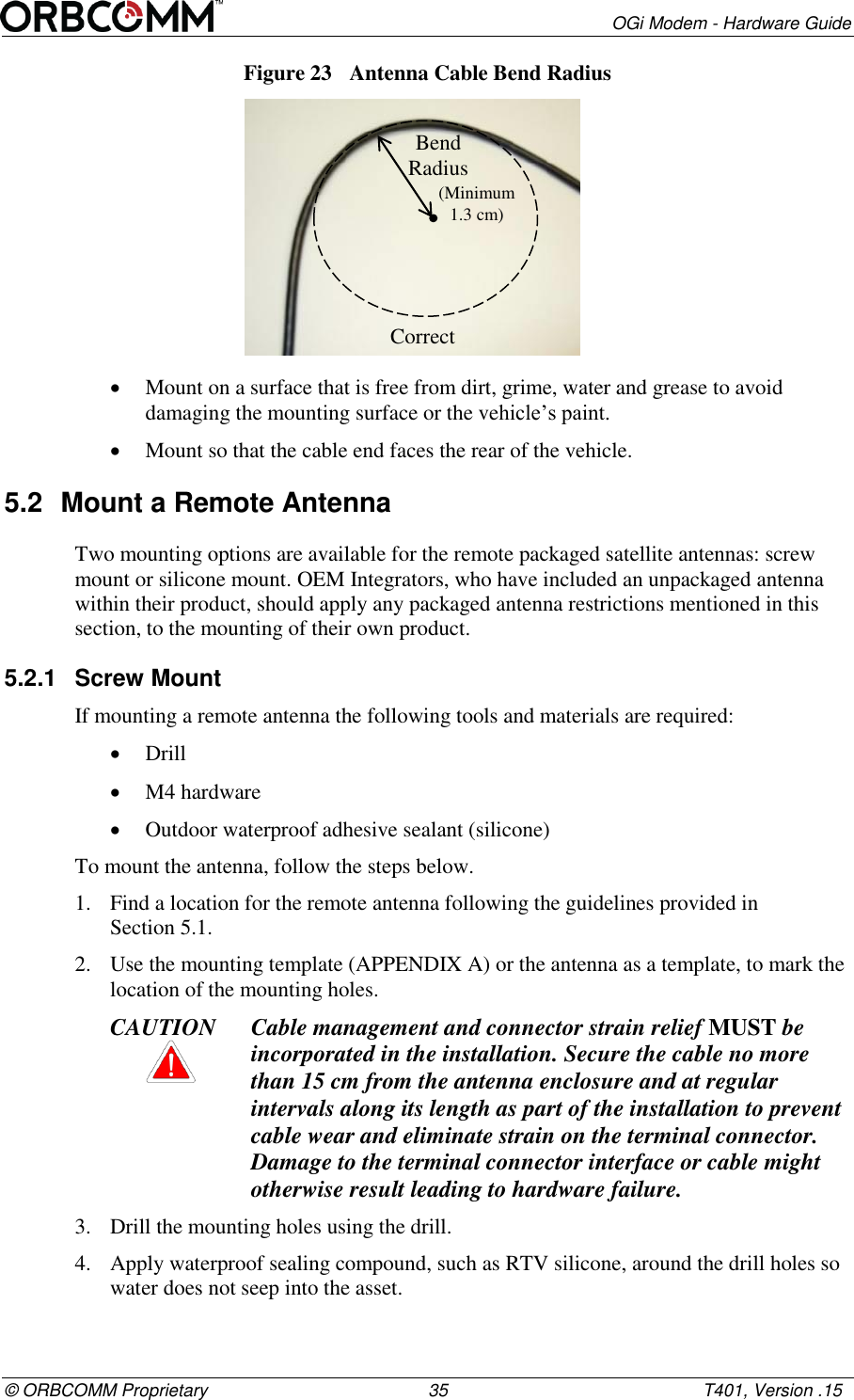
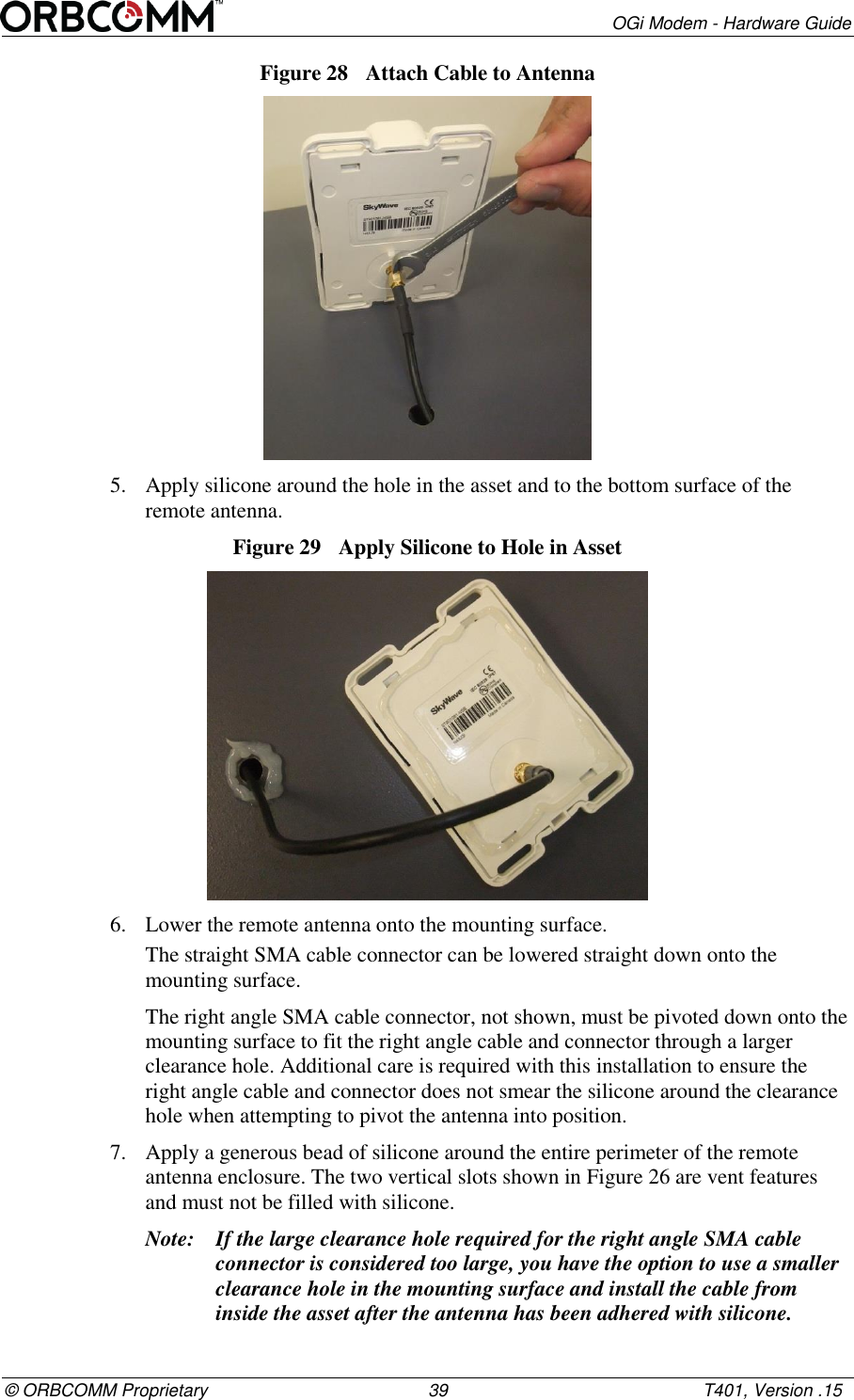
![OGi Modem - Hardware Guide T401, Version .15 vi © ORBCOMM Proprietary Preface Purpose This document provides an overview of the hardware characteristics and specifications for the OGi modem. Errata Sheet Refer to the SkyWave Customer Support website for updates or for an Errata Sheet that might be available after the release of this document. Always check the website for the most current documentation. Audience This document is for technical readers. It provides information to ensure successful integration of the OGi modem. Notation An OEM Integrator is an ORBCOMM customer who purchases an OGi modem for integration into their own enclosure. To become an OEM Integrator certain commercial criteria must be met. Contact your Account Executive for further details. Hardware components and hardware labels in this document might not be exactly as shown and are subject to change without notice. CAUTION This safety symbol warns of possible hazards to personnel, equipment, or both. It includes hazards that will or can cause personal injury, property damage, or death if the hazard is not avoided. Note: A note indicates information with no potential hazard. A note indicates points of interest or provides supplementary information about a feature or task. Numbered lists indicate a series of steps required to complete a task or function. Bulleted lists highlight information where order or sequence is not crucial. Reference The content of the following documents might be useful in conjunction with this guide. These documents are available from the downloads section at support.skywave.com or from the OG Toolkit, which is also available from the website. [T402] OG Interface Developer Guide [T403] AT Interface Developer Guide Safety Disclaimer ORBCOMM makes no warranties, representations or guarantees that the products and network services are suitable for any use in any hazardous environments requiring fail](https://usermanual.wiki/ORBCOMM-License/OGI100/User-Guide-2918569-Page-6.png)