ORION ELECTRIC M4C8F VCR User Manual Instruction Book
ORION ELECTRIC CO., LTD. VCR Instruction Book
Instruction Book
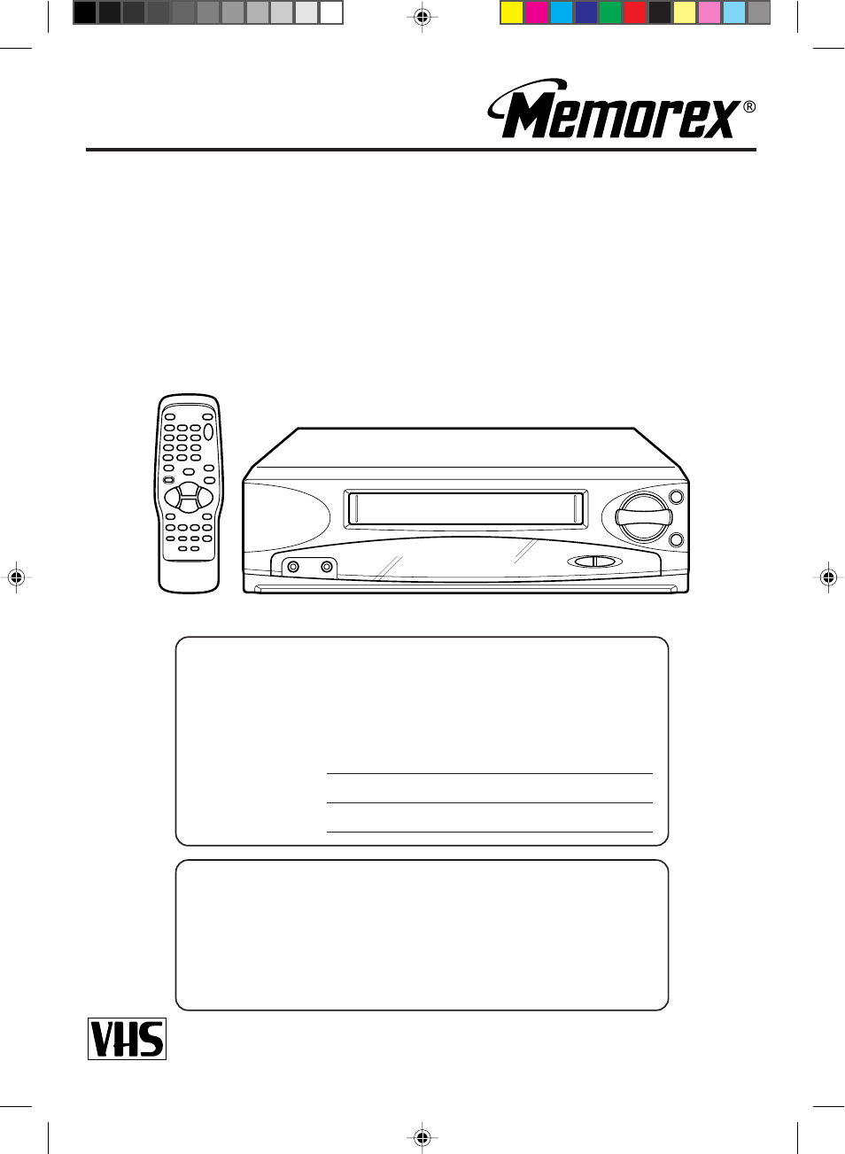
VIDEO CASSETTE RECORDER
VIDEOGRABADOR DE CASSETTE
OWNER'S MANUAL
MANUAL DE INSTRUCCIONES
Before operating the unit, please read this manual thoroughly.
Antes de utilizar su aparato favor de leer las siguientes instrucciones.
MVR2040A
ATTENTION
ATENCION
For your protection in the event of theft or loss of this product, please fill in the
information listed below which is for your own personal records.
Por su precaucion en caso de robo o pérdida de este producto, favor de llenar
la información listada baja que es para sus inscripciones personales de usted.
Date of purchase :
Fecha de compra :
Serial No. :
Número de serie :
Place od Purchase :
Lugar de compra :
TV/CATV MODE SELECTION
SELECCION DE MODO DE TV/CATV
When shipped from the factory, the TV/CATV menu option is set to the "CATV"
(Cable Television) mode.
If not using CATV (Cable TV), set this menu option to the "TV" mode.
A la salida de fábrica, la opción de menú TV/CATV está en el modo "CATV"
(televisión por cable).
Si no se va a utilizar el CATV (TV cable), cambie la opción de este menú al
modo TV.
4C83501A-E(C-09) 27*10*99, 11:371
2
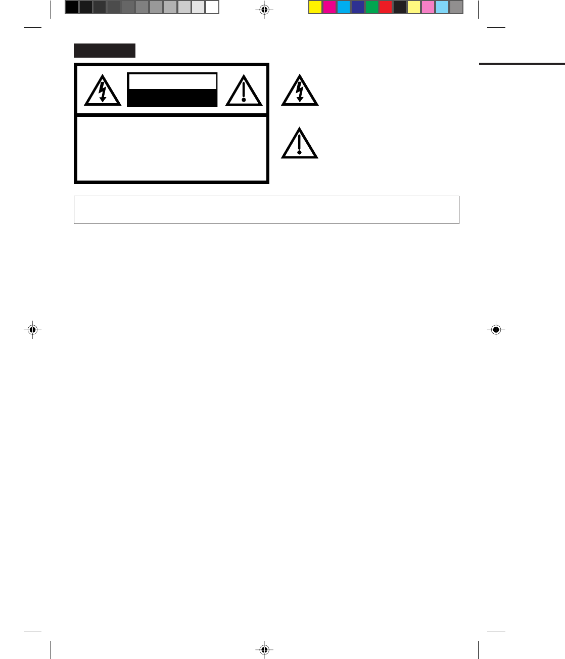
RISK OF ELECTRIC SHOCK
DO NOT OPEN
CAUTION
The exclamation point within an equilateral
triangle is intended to alert the user to the
presence of important operating and
maintenance (servicing) instructions in the
literature accompanying the appliance.
The lightning flash with arrowhead symbol
within an equilateral triangle is intended to
alert the user to the presence of
uninsulated dangerous voltage within the
product's enclosure that may be of
sufficient magnitude to constitute a risk of
electric shock to persons.
TO REDUCE THE RISK OF ELECTRIC
SHOCK, DO NOT REMOVE COVER (OR
BACK). NO USER-SERVICEABLE PARTS
INSIDE. REFER SERVICING TO QUALI-
FIED SERVICE PERSONNEL.
CAUTION:
TO REDUCE THE RISK OF FIRE OR ELECTRIC SHOCK, DO NOT EXPOSE THIS APPLIANCE TO
RAIN OR MOISTURE.
WARNING:
WARNING: This equipment has been tested and found to comply with the limits for a Class B digital device,
pursuant to Part 15 of the FCC Rules. These limits are designed to provide reasonable protection
against harmful interference in a residential installation. This equipment generates, uses and can
radiate radio frequency energy and, if not installed and used in accordance with the instructions, may
cause harmful interference to radio communications.
However, there is no guarantee that interference will not occur in a particular installation. If this equip-
ment does cause harmful interference to radio or television reception, which can be determined by
turning the equipment off and on, the user is encouraged to try to correct the interference by one or
more of the following measures:
-
-
-
-
Reorient or relocate the receiving antenna.
Increase the separation between the equipment and receiver.
Connect the equipment into an outlet on a circuit different from that to which the receiver is connected.
Consult the dealer or an experienced radio/TV technician for help.
Changes or modifications not expressly approved by the partly responsible for compliance with the
FCC Rules could void the user's authority to operate this equipment.
CAUTION:
ENGLISH
4C83501A-E(C-09) 27*10*99, 11:372
3
ENGLISH
READ INSTRUCTIONS
All the safety and operating instructions should be read before the unit is operated.
RETAIN INSTRUCTIONS
The safety and operating instructions should be retained for future reference.
HEED WARNINGS
All warnings on the unit and in the operating instructions should be adhered to.
FOLLOW INSTRUCTIONS
All operating and use instructions should be followed.
CLEANING
Unplug this unit from the wall outlet before cleaning. Do not use liquid cleaners or aerosol cleaners.
Use a damp cloth for cleaning.
ATTACHMENTS
Do not use attachments not recommended by the unit's manufacturer as they may cause hazards.
WATER AND MOISTURE
Do not use this unit near water. For example, near a bathtub, washbowl, kitchen sink, or laundry tub, in a wet
basement, or near a swimming pool.
ACCESSORIES
Do not place this unit on an unstable cart, stand, tripod, bracket, or table. The unit may
fall, causing serious injury, and serious damage to the unit. Use only with a cart, stand,
tripod, bracket, or table recommended by the manufacturer.
An appliance and cart combination should be moved with care. Quick stops, excessive
force, and uneven surfaces may cause the appliance and cart combination to overturn.
VENTILATION
Slots and openings in the cabinet and in the back or bottom are provided for ventilation and to ensure reliable
operation of the unit and to protect it from overheating. These openings must not be blocked or covered. The
openings should never be blocked by placing the unit on a bed, sofa, rug, or other similar surface. This unit
should never be placed near or over a radiator or heat source. This unit should not be placed in built-in installa-
tions such as a bookcase or rack unless proper ventilation is provided or the manufacturer's instructions have
been adhered to.
POWER SOURCES
This unit should be operated only from the type of power source indicated on the rating plate. If you are not
sure of the type of power supply to your home, consult your appliance dealer or local power company. For units
intended to operate from battery power, or other sources, refer to the operating instructions.
GROUNDING OR POLARIZATION
This unit is equipped with a polarized alternating-current line plug (a plug having one blade wider than the
other). This plug will fit into the power outlet only one way. This is a safety feature. If you are unable to insert
the plug fully into the outlet, try reversing the plug. If the plug should still fail to fit, contact your electrician to
replace your obsolete outlet. Do not defeat the safety purpose of the polarized plug If your unit is equipped with a
3-wire grounding-type plug, a plug having a third (grounding) pin, this plug will only fit into a grounding-type
power outlet. This too, is a safety feature. If you are unable to insert the plug into the outlet, contact your
electrician to replace your obsolete outlet.
Do not defeat the safety purpose of the grounding-type plug.
1.
2.
3.
4.
5.
6.
7.
8.
8A.
9.
10.
11.
IMPORTANT SAFEGUARDS
S3125A
PORTABLE CART WARNING
(symbol provided by RETAC)
4C83501A-E(C-09) 27*10*99, 11:373

4
POWER-CORD PROTECTION
Power-supply cords should be routed so that they are not likely to be walked on or pinched by items placed
upon or against them, paying particular attention to cords at plugs, convenience receptacles, and the point
where they exit from the appliance.
LIGHTNING
To protect your unit from a lightning storm, or when it is left unattended and unused for long periods of time,
unplug it from the wall outlet and disconnect the antenna or cable system. This will prevent damage to the unit
due to lightning and power line surges.
POWER LINES
An outside antenna system should not be located in the vicinity of overhead power lines or other electric light or
power circuits, or where it can fall into such power lines or circuits. When installing an outside antenna system,
extreme care should be taken to keep from touching such power lines or circuits, as contact with them might be
fatal.
OVERLOADING
Do not overload wall outlets and extension cords, as this can result in a risk of fire or electric shock.
OBJECT AND LIQUID ENTRY
Do not push objects through any openings in this unit as they may touch dangerous voltage points or short out
parts that could result in fire or electric shock. Never spill or spray any type of liquid into the unit.
OUTDOOR ANTENNA GROUNDING
If an outside antenna or cable system is connected to the unit, be sure the antenna or cable system is grounded
so as to provide some protection against voltage surges and built-up static charges. Section 810 of the National
Electrical Code, ANSI/NFPA 70, provides information with respect to proper grounding of the mast and support-
ing structure, grounding of the lead-in wire to an antenna discharge unit, size of grounding conductors, location
of antenna discharge unit, connection to grounding electrodes, and requirements for the grounding electrode.
SERVICING
Do not attempt to service this unit yourself as opening or removing covers may expose you to dangerous
voltage or other hazards. Refer all servicing to qualified service personnel.
DAMAGE REQUIRING SERVICE
Unplug this unit from the wall outlet and refer servicing to qualified service personnel under the following
conditions:
REPLACEMENT PARTS
When replacement parts are required, be sure the service technician uses replacement parts specified by the
manufacturer or those that have the same characteristics as the original parts.
Unauthorized substitutions may result in fire, electric shock or other hazards.
When the power-supply cord or plug is damaged.
If liquid has been spilled, or objects have fallen into the unit.
If the unit has been exposed to rain or water.
If the unit does not operate normally by following the operating instructions. Adjust only those
controls that are covered by the operating instructions, as an improper adjustment of other controls
may result in damage and will often require extensive work by a qualified technician to restore the
unit to its normal operation.
If the unit has been dropped or the cabinet has been damaged.
When the unit exhibits a distinct change in performance, this indicates a need for service.
a.
b.
c.
d.
e.
f.
12.
13.
14.
15.
16.
17.
18.
19.
20.
IMPORTANT SAFEGUARDS (CONTINUED)
4C83501A-E(C-09) 27*10*99, 11:374
5
ENGLISH
SAFETY CHECK
Upon completion of any service or repairs to this unit, ask the service technician to perform safety checks to
determine that the unit is in proper operating condition.
WALL OR CEILING MOUNTING
The product should be mounted to a wall or ceiling only as recommended by the manufacturer.
HEAT
The product should be situated away from heat sources such as radiators, heat registers, stoves, or other
products (including amplifiers) that produce heat.
NOTE TO CATV SYSTEM INSTALLER
This reminder is provided to call the CATV system installer's attention to Article 820-40 of the NEC that provides
guidelines for proper grounding and, in particular, specifies that the cable ground shall be connected to the
grounding system of the building, as close to the point of cable entry as practical.
21.
22.
23.
24.
ANTENNA
DISCHARGE UNIT
(NEC SECTION 810-20)
ANTENNA
LEAD IN
WIRE
POWER SERVICE GROUNDING
ELECTRODE SYSTEM
(NEC ART 250, PART H)
GROUND
CLAMP
ELECTRIC
SERVICE
EQUIPMENT
NEC-NATIONAL ELECTRICAL CODE
GROUND CLAMPS
GROUNDING CONDUC-
TORS
(NEC SECTION 810-21)
S2898A
EXAMPLE OF ANTENNA GROUNDING AS PER THE
NATIONAL ELECTRICAL CODE
4C83501A-E(C-09) 27*10*99, 11:375

6
FEATURES
High Quality Picture Technology - This video cassette recorder marked "HQ" incorporates VHS high quality
technology. A built-in detail enhancer is used to boost the recorded signal and provide maximum picture
quality in playback. It is compatible with other VHS video cassette recorders.
Frequency Synthesized Tuning - Quartz locked direct access tuner automatically locks in each channel for
perfect reception.
4 Video Heads - Provides optimal picture quality for special effects playback.
Full Load Tape Transport - Permits rapid access between modes.
8-Program/1-Month Programmable Timer with Everyday/Every Week Capability - The built-in timer allows
automatic absentee recording of up to 8 TV programs within 1month. It is also possible to record a program
which is broadcast at the same time everyday or every week.
On-Screen Display and Programming - When you select a channel or make other changes, the TV will show
an indicator on the screen for a few seconds. Clock settings, timer setting and other set-up operations can be
carried out using the on-screen display menu system.
Digital Auto Tracking - Automatically adjusts tracking during playback for the best possible picture.
181 Channel Tuner - Receives standard VHF and UHF broadcast channels and up to 113 cable channels.
One-Touch Timer Recording (OTR) - Simply by pressing the REC/OTR button, the VCR can be programmed
for up to 5 hours of recording with an immediate start.
Automatic Power On - When loading a cassette tape, this VCR will automatically turn on.
Automatic Playback - When loading a cassette tape without the erase prevention tab, this VCR will
automatically turn on and play back the cassette tape at the correct speed.
Automatic Rewind-Stop-Eject-Power Off - When a tape reaches its end during playback and recording, it will
automatically stop, rewind, stop, eject the tape and the VCR will turn off.
Automatic Repeat Play System - When the AUTO REPEAT option is turned on, this VCR will automatically
play back the same cassette tape repeatedly.
On-Screen 3 Language Display - You can select one of 3 languages; English, Spanish or French, for on-
screen programming.
Slow Motion - This VCR provide slow motion which offers steady, noise-free playback at 1/10 normal speed.
Frame by Frame Advance - Press the SLOW button during still playback to advance the tape one frame at a
time.
Skip Search - When the SKIP SEARCH button is pressed during playback, the TV/VCR will automatically
search forward in 30 second increments to amaximum of 3 minutes with each press of the SKIP SEARCH
button, and then return to normal playback.
Real Time Tape Counter - The counter displays on the screen the elapsed time in hours, minutes and
seconds and can be used to locate programs.
Channel Skip - An unwanted channel can be deleted when using the CHANNEL ▲ or ▼ button.
Fluorescent Multi-Function Display - Selected functions are immediately indicated on the display.
2 Speed Picture Search - 3 or 5 times normal speed in SP mode (7X or 9X in LP and 9X or 15X in SLP).
3 Speed Record/Playback - Records and plays three tape speeds (SP, LP, SLP).
Auto Head Cleaning System - Cleans the video heads automatically when a cassette tape is loaded and
ejected.
Audio/Video Input/Output Jack - A VCR or other video device may be hooked up to this VCR for dubbing or
playback purposes.
4C83501A-E(C-09) 27*10*99, 11:376
7
ENGLISH
PRECAUTIONS
We recommend that you carefully read the descriptions and operating procedures contained in this Owner's
Manual prior to operating your new VCR.
TABLE OF CONTENTS
PRECAUTIONS ....................................................................................................................................................... 8
LOCATION OF CONTROLS .................................................................................................................................. 10
REMOTE CONTROL ............................................................................................................................................. 12
BASIC CONNECTIONS ......................................................................................................................................... 14
CATV (CABLE TV) CONNECTIONS ..................................................................................................................... 18
AUDIO/VIDEO CONNECTIONS ............................................................................................................................ 22
SETTING THE VIDEO CHANNEL ......................................................................................................................... 23
ON-SCREEN LANGUAGE SELECTION ............................................................................................................... 24
SETTING THE CLOCK .......................................................................................................................................... 25
SETTING THE CHANNELS ................................................................................................................................... 26
NOISE ELIMINATION (BLUE SCREEN) ............................................................................................................... 29
PLAYBACK
RECORDING
RECORDING A TV PROGRAM............................................................................................................................. 36
ONE TOUCH TIMER RECORDING (OTR) ........................................................................................................... 39
SETTING THE TIMER RECORDING .................................................................................................................... 40
LOADING AND UNLOADING VIDEO CASSETTE TAPES ......................................................................................30
PLAYBACK ............................................................................................................................................................ 31
SPECIAL PLAYBACK ............................................................................................................................................ 33
ON-SCREEN FUNCTION DISPLAY ...................................................................................................................... 43
DUPLICATING A VIDEO TAPE ............................................................................................................................. 44
VIDEO HEAD CLEANING...................................................................................................................................... 45
BEFORE REQUESTING SERVICE ....................................................................................................................... 46
SPECIFICATIONS ................................................................................................................................................. 48
ADDITIONAL INFORMATION
4C83501A-E(C-09) 27*10*99, 11:377
8
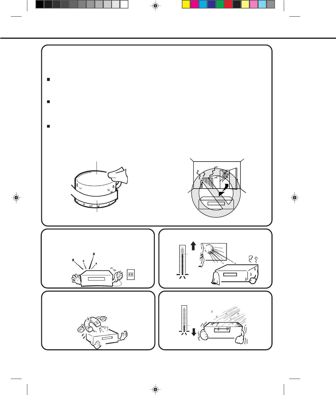
WHAT IS MOISTURE CONDENSATION?
MOISTURE WILL CONDENSE ON THE UNIT IN THE FOLLOWING CASES;
WHEN YOU EXPERIENCE THE ABOVE CONDITIONS,
When a cold liquid is poured into a glass, for example, water vapor in the air will condense on the surface of the
glass. This is called moisture condensation.
When you move this VCR from a cold to a warm place.
After heating a cold room or under extremely humid conditions.
Plug the power cord into an AC outlet, set the power switch to ON and leave the unit at room temperature until
moisture condensation disappears.
Depending on the surrounding conditions, this may take two or three hours.
MOISTURE CONDENSATION
DO NOT OPERATE THIS VCR FOR AT LEAST TWO OR THREE HOURS WHEN MOISTURE IN THE AIR
CONDENSES ON THE VCR.
PRECAUTIONS
•
•
(5
°
C)
41
°
F
104
°
F
(40
°
C)
Head Drum
Video Tape
If you cause a static discharge when touching the
VCR, and the VCR fails to function, simply unplug the
unit from the wall outlet, wait a few minutes and plug
it back in. The VCR should return to normal operation.
Avoid extreme heat.
Avoid extreme cold.
Do not place the VCR on or near appliances which
may cause electromagnetic interference, e.g. TV,
speakers, etc. Doing so may cause erratic operation
of the VCR including picture and/or sound distortion
or noise.
4C83501A-E(C-09) 27*10*99, 11:378
9
ENGLISH
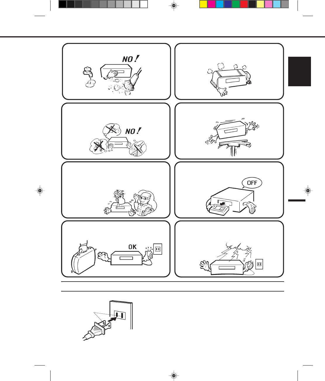
POWER SOURCE
When you leave your home for a long time, unplug
the AC power cord.
Avoid places subject to strong vibration. Use in a
horizontal (flat) position only.
Avoid extreme moisture and dust.
Do not insert fingers or any other objects into the
cassette loading slot. Do not spray cleaner or wax
directly on the VCR or use forced air to remove dust.
The ventilation holes prevent overheating. Do not
block or cover these holes. Especially avoid covering
the holes with soft materials such as cloth or paper.
When you finish operating the VCR, always unload
the cassette and turn off the power.
Keep the VCR away from flower vases, sinks, etc.
If liquids should be spilled into the VCR, serious
damage will result. If you spill any liquids into the
VCR, unplug the AC power cord immediately and
consult qualified service personnel before attempting
to use the VCR again.
To protect the VCR from a lightning storm, unplug
the AC power cord from the wall outlet and
disconnect the antenna.
TO USE AC POWER SOURCE
Use the AC polarized line cord provided for operation on AC. Insert the
AC cord plug into a standard 120V 60Hz polarized AC outlet.
NOTES:
1. Never connect the AC line cord plug to other than the specified
voltage (120V 60Hz). Use the attached power cord only.
2. If the polarized AC cord does not fit into a non-polarized AC
outlet, do not attempt to file or cut the blade. It is the user’s
responsibility to have an electrician replace the obsolete outlet.
3. If you cause a static discharge when touching the unit, and the
unit fails to function, simply unplug the unit, from the AC outlet,
wait a few minutes, and plug it back in. The unit should return to
normal operation.
Polarized AC Cord Plug
(One blade is wider than the other.)
AC Outlet
Wider Hole
and Blade
4C83501A-E(C-09) 27*10*99, 11:379
10
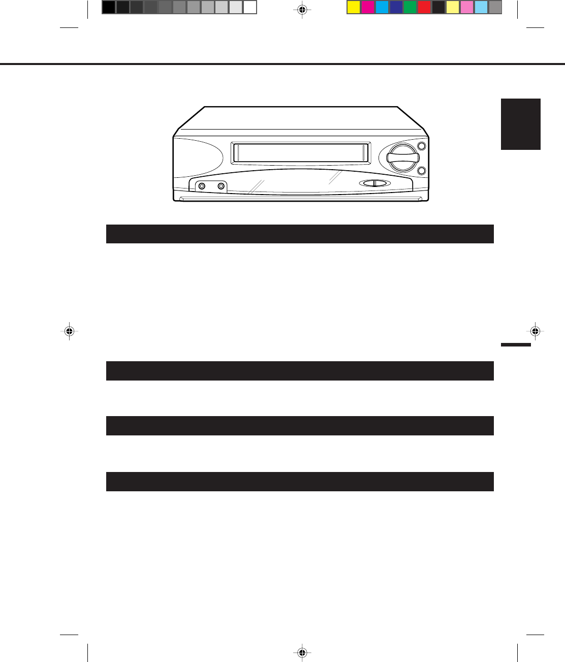
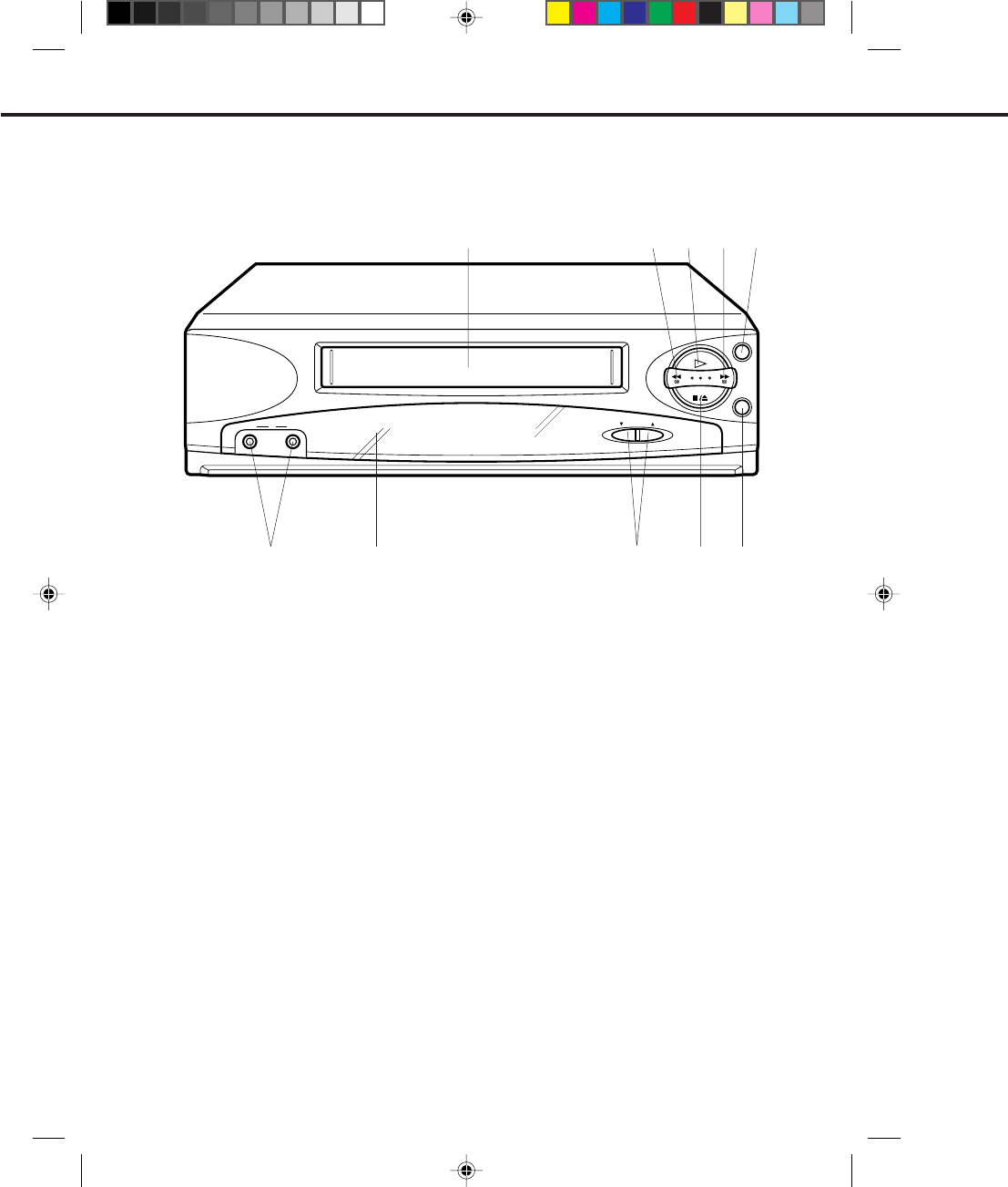
CHANNEL
STOP/EJECT
PLAY
POWER
REC/OTR
VIDEDO AUDIOIN
LOCATION OF CONTROLS
DESCRIPTION OF CONTROLS
1.
2.
3.
4.
5.
6.
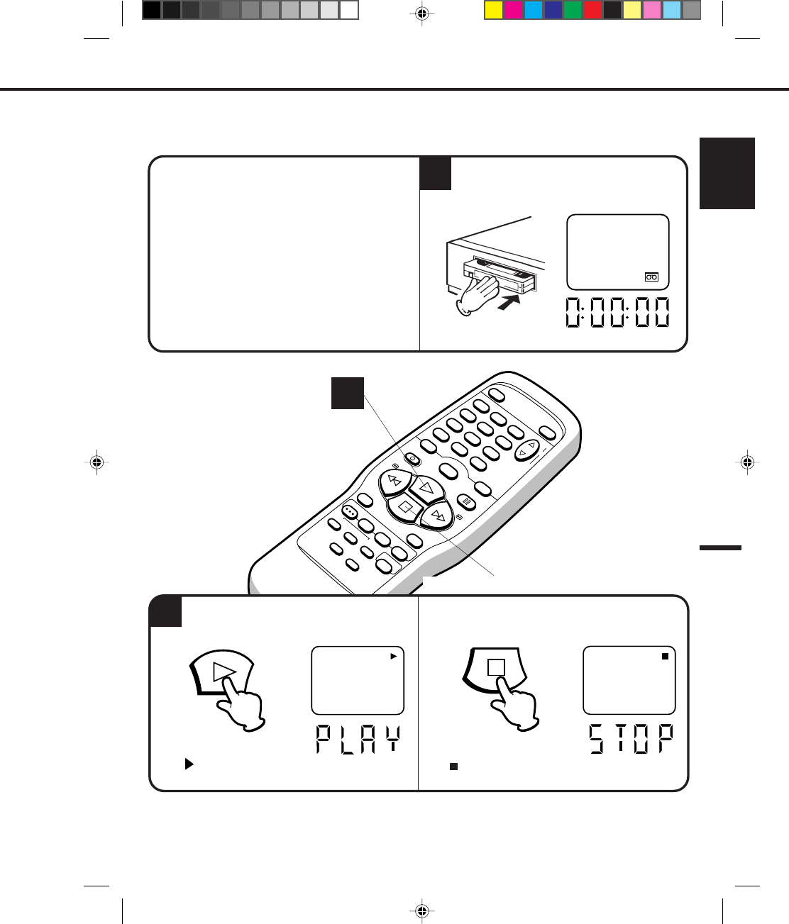
Cassette Loading Slot - To insert or remove a
video tape.
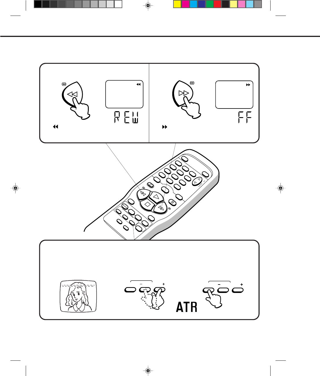
REW button - In the STOP mode, this button rapidly
winds the tape backwards. In the PLAY mode, this
button activates Reverse Search.
PLAY button - Press to play a prerecorded tape.
F. FWD button - In the STOP mode, this button
rapidly winds the tape forward. In the PLAY mode,
this button activates Forward Search.
POWER button - Turns the VCR power on and off.
REC/OTR button - Press once to start normal
recording. Additional presses activate One Touch
Recording.
7.
8.
9.
10.
STOP/EJECT button - Press once to stop the tape
in any mode. Press again (on the VCR) to eject
the tape.
CHANNEL ▲ / ▼ buttons - Used to select a
channel for viewing or recording.
Remote Sensor - Signals from the Remote Control
are received here.
AUDIO/VIDEO IN Jacks - Audio and video signal
cables from an external source can be connected
here.
FRONT
1 2
7
453
968
10
4C83501A-E(P10-19) 27*10*99, 11:3610
11
ENGLISH
UHF/VHF
OUT(TV)
IN(ANT)
3
CH
4
VIDEO
OUT
AUDIO
5 3
2
DESCRIPTION OF CONTROLS
AUDIO/VIDEO OUT Jacks - Used to output audio
and video signals to a TV, amplifier or VCR.
VHF/UHF IN (ANT) Jack - Connect a VHF/UHF
antenna or CATV cable to this jack.
VHF/UHF OUT (TV) Jack - Used to output VHF/
UHF or CATV signals to a TV.
1.
2.
3.
4.
5.
3/4 Channel Selector Switch - Selects the channel
through which the VCR outputs its signal to a TV.
AC Power Cord - Connect to a 120V 60Hz outlet.
REAR
LOCATION OF CONNECTORS
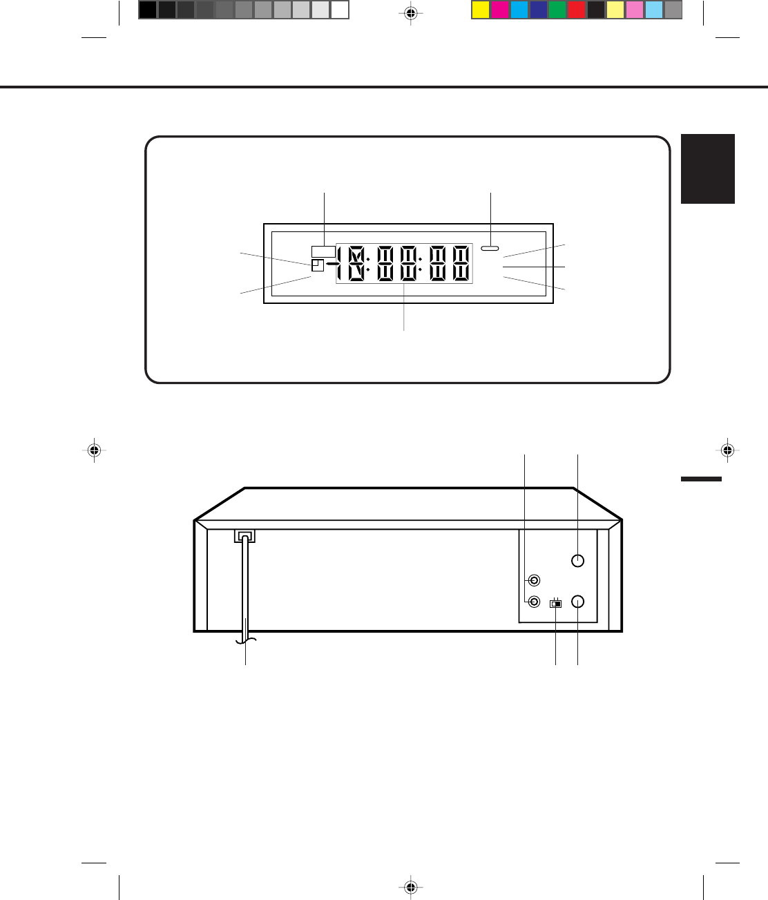
FLUORESCENT DISPLAY
OTR
SLP
VCR
ATR
APM
One Touch Timer
Recording POWER indicator
Timer Record
Tape Speed
ATR (Auto Tracking)
VCR
AM/PM
Multi-Function Display
1
4
4C83501A-E(P10-19) 27*10*99, 11:3611
12
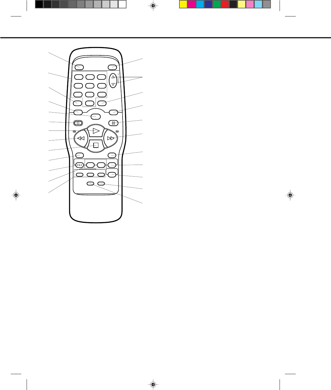
REMOTE CONTROL
9.
10.
11.
12.
13.
14.
15.
16.
17.
18.
19.
20.
21.
22.
23.
24.
STOP button - Press once to stop the tape.
SPEED (SP/LP/SLP) selector button - Sets
the tape speed for recording.
MENU button - Press to display the on-screen menu
function.
SET +/– buttons - Used to set or adjust in the menu
mode.
DIGITAL AUTO/MANUAL TRACKING buttons -
Allow automatic or manual adjustment of tracking to
minimize picture noise during playback.
EJECT button - Press to eject the tape.
CHANNEL ▲ / ▼ buttons - Used to select a
channel for viewing or recording.
TV/VCR selector button - Switches between TV
and VCR.
COUNTER RESET button - Resets the Real Time
Counter to "00:00:00".
PAUSE/STILL button - During recording, this
button temporarily stops the tape. During playback, it
stops the tape and displays a still image on the TV
screen.
F. FWD button - In the STOP mode, this button
rapidly winds the tape forward. In the PLAY mode,
this button activates Forward Search.
ENTER button - Used to enter information in the
menu mode.
CANCEL button - Used to clear the selected timer
recording program and to move the cursor backward
for correction.
TIMER REC button - Used to set the VCR to start
recording at a preset time.
CLOCK/COUNTER selector button - Switches
between the clock and the real time tape counter.
SKIP SEARCH button - Press in the playback mode
to search forward in 30 second increments to a
maximum of 3 minutes.
POWER button - Turns the VCR power on and off.
Direct Channel Selection buttons (0-9) - Allow
direct access to any channel.
CALL button - Displays the status of the unit on the
TV screen.
INPUT SELECT button - Switches the program for
viewing between the VCR and external input sources.
SLOW button - Press to play back a tape in slow
motion or to advance the tape one frame at a time
during still playback.
REC/OTR button - Press once to start normal
recording. Additional presses activate One-touch
Timer Recording.
PLAY button - Press to play a prerecorded tape.
REW button - In the STOP mode, this button
rapidly winds the tape backwards. In the PLAY
mode, this button activates Reverse Search.
DESCRIPTION OF BUTTONS
1
1.
2.
3.
4.
5.
6.
7.
8.
POWER EJECT
TV/VCR
COUNTER RESETINPUT SELECT
REC/OTR
SPEED
PLAY
STOP
F.FWDREW
MENU SET
TRACKING
SKIP
SEARCH CLOCK/
COUNTER
AUTO
ENTER
TIMER REC
PAUSE/STILL
CHANNEL
CALL
123
456
78
0
9
–
+
–+
SET
–+
CANCEL
SLOW
2
13
3
11
12
10
9
8
7
6
5
4
24
23
22
21
20
19
18
17
16
15
14
4C83501A-E(P10-19) 27*10*99, 11:3612
13
ENGLISH
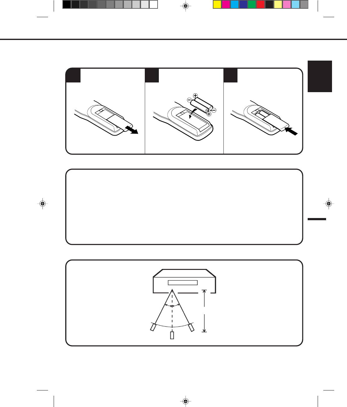
1
Use only the size and type of batteries specified.
Be sure to follow the correct polarity when installing the batteries as indicated in the battery compartment.
Reversed batteries may cause damage to the device.
Do not mix different types of batteries together (e.g. Alkaline and Carbon-zinc) or old batteries with fresh
ones.
If the device is not to be used for a long period of time, remove the batteries to prevent damage or injury
from possible battery leakage.
Do not try to recharge batteries not intended to be recharged; they can overheat and rupture. (Follow
battery manufacturer's directions.)
Follow these precautions when using batteries in this device:
BATTERY INSTALLATION
BATTERY CAUTIONS
1.
2.
3.
4.
5.
Replace the cover.
Install two "AAA" (penlight
size) batteries.
Open the battery compart-
ment cover.
EFFECTIVE DISTANCE OF THE REMOTE CONTROL TRANSMITTER
NOTE: When direct sunlight, an incandescent lamp, fluorescent lamp or any other strong light shines on the
Remote Sensor, the remote operation may be unstable.
When there is an obstacle between the VCR and the transmitter, the remote control transmitter may not
operate.
•
•
23
15 FEET
30°30°
4C83501A-E(P10-19) 27*10*99, 11:3613
14
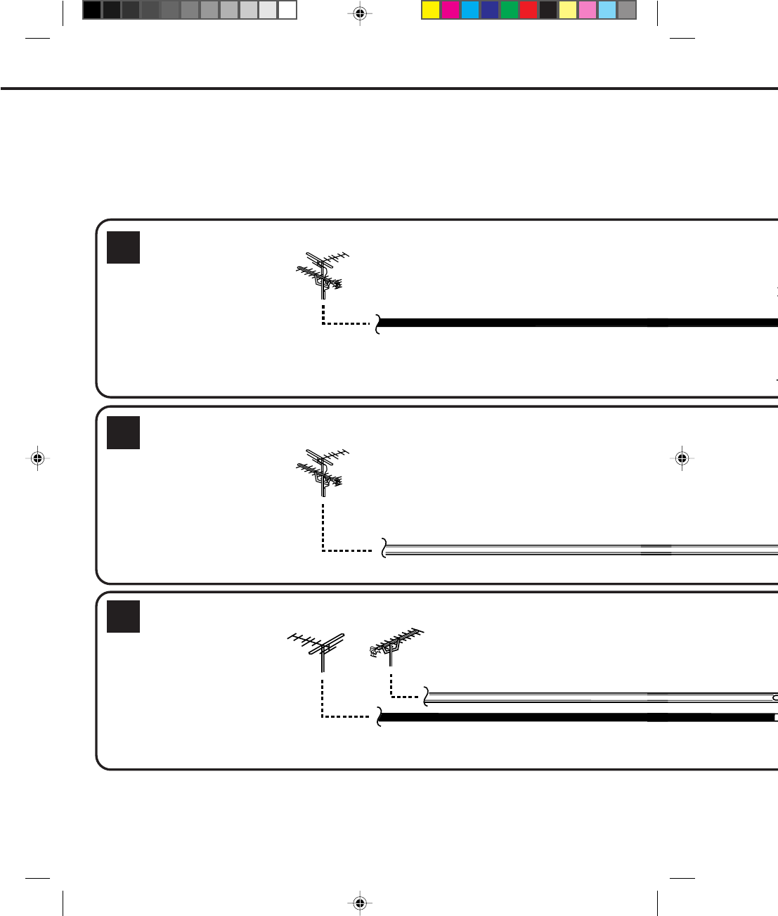
COMBINATION VHF/UHF ANTENNA WITH 75 OHM COAXIAL CABLE
COMBINATION VHF/UHF ANTENNA WITH 300 OHM TWIN LEAD (FLAT) WIRE
SEPARATE VHF AND UHF ANTENNAS
VHF
3
1
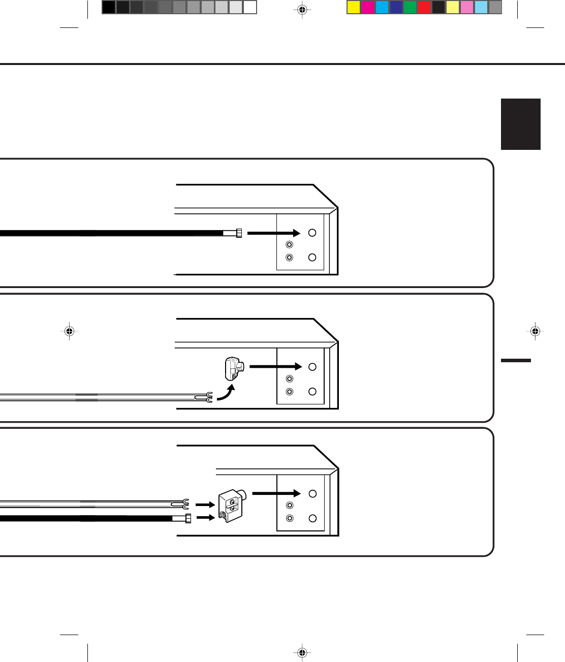
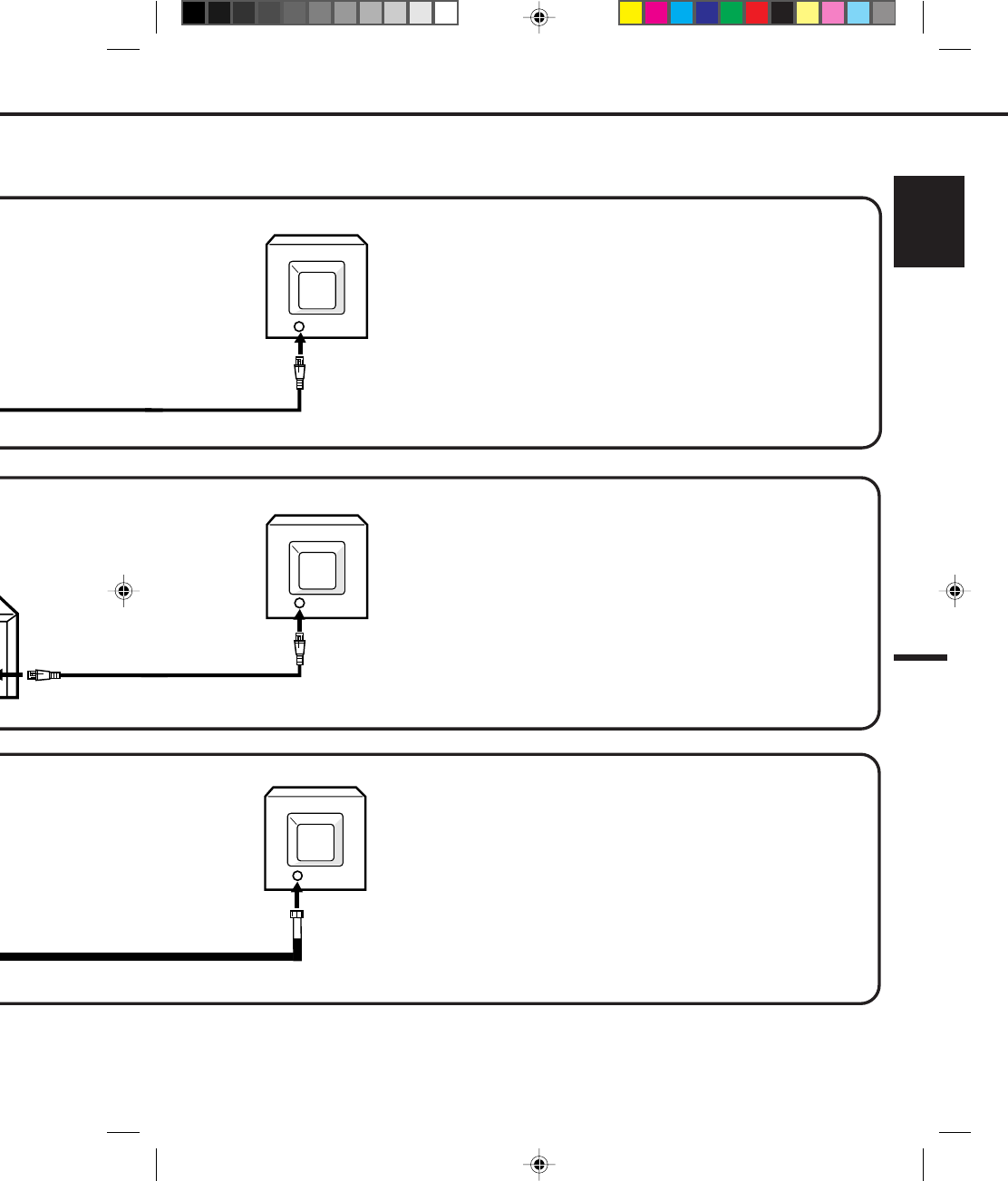
A clear picture will not be obtained by the VCR unless the antenna signal is good. Connect the antenna to
the VCR properly.
For better quality recording, an indoor antenna or a telescopic antenna is not recommended. The use of an
outdoor type antenna is required.
If you are not sure about the connection, please refer to qualified service personnel.
•
•
•
If you are using an antenna system, follow the instructions on pages 14-17. If you are a cable (CATV) subscriber,
skip ahead to page 18 for the proper connections.
ANTENNA TO VCR CONNECTION
The VCR must be connected "between" the antenna and the TV. First, disconnect the antenna from the TV and connect
it to the VCR. Then connect the VCR to the TV. Below are 3 common methods of connecting an antenna system to a
VCR. Find the type of antenna system you are using and follow the connection diagram. After you have connected the
antenna to the VCR, follow the instructions on pages 16-17 to connect the VCR to the TV.
BASIC CONNECTIONS
UHF
300 OHM TWIN LEAD (FLAT) WIRE
300 OHM TWIN LEAD (FLAT) WIRE
75 OHM COAXIAL CABLE
75 OHM COAXIAL CABLE
If both VHF and UHF antennas have 300 ohm twin lead (flat) wires, use a combiner having two 300 ohm
inputs and one 75 ohm output.
NOTE:
NOTE:
2
4C83501A-E(P10-19) 27*10*99, 11:3614
15
ENGLISH
OUT
IN
OUT
IN
OUT
IN
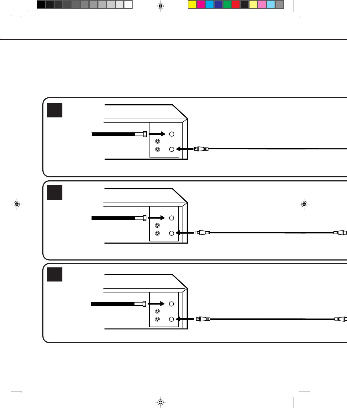
NOTE: IF A VHF OR UHF
ANTENNA IS USED, SET THE TV/
CATV MENU OPTION TO THE
"TV" MODE.
NOTE: IF A VHF OR UHF
ANTENNA IS USED, SET THE TV/
CATV MENU OPTION TO THE
"TV" MODE.
NOTE: IF A VHF OR UHF
ANTENNA IS USED, SET THE TV/
CATV MENU OPTION TO THE
"TV" MODE.
COMBINER
75/300 OHM INPUTS
75 OHM OUTPUT
(NOT SUPPLIED)
VCR
VCR
VCR
MATCHING TRANSFORMER
300 OHM INPUT
75 OHM OUTPUT
(NOT SUPPLIED)
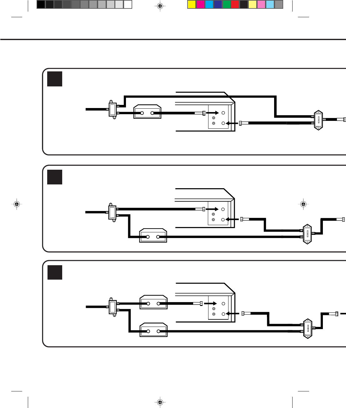
This VCR has a single 75 ohm antenna input for connection to an antenna (VHF/UHF) or cable (CATV) system.
If you have separate VHF and UHF antennas (number 3 below), use a combiner to connect the antennas to
the VCR.
4C83501A-E(P10-19) 27*10*99, 11:3615
16
OUT
IN
OUT
IN
OUT
IN
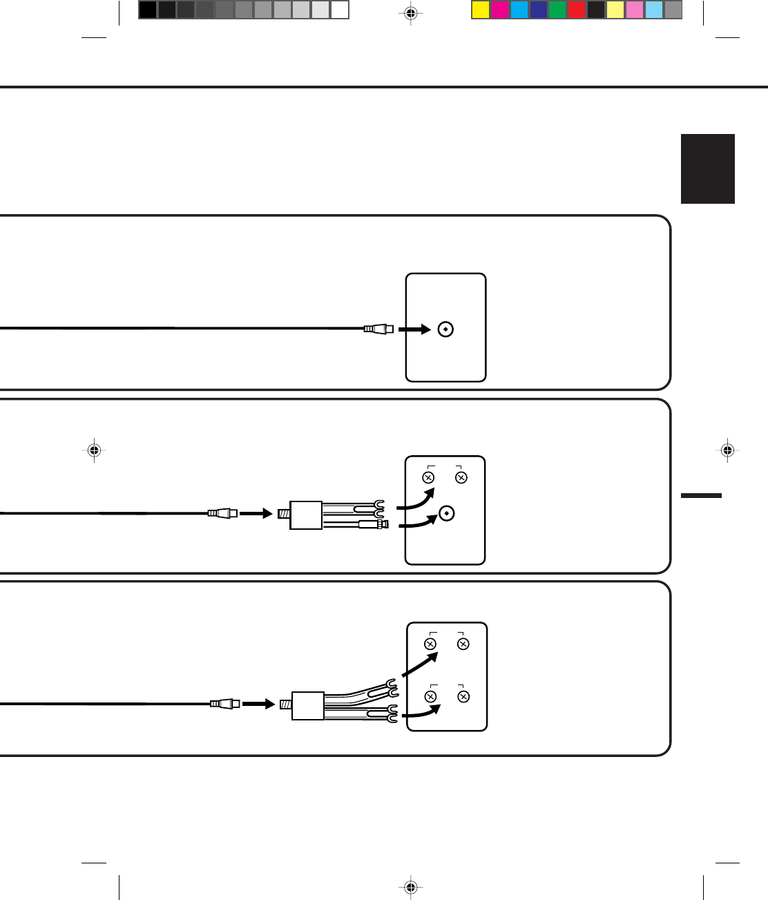
VCR TO TV CONNECTION
After you have connected the antenna to the VCR (see pages 14 & 15), you must connect the VCR to the TV.
Below are 3 common methods of connecting your VCR to a TV. Find the type of TV you are using and follow
the connection diagram.
2
1
3
BASIC CONNECTIONS (CONTINUED)
VCR
VCR
VCR
75 OHM COAXIAL CABLE (SUPPLIED)
75 OHM COAXIAL CABLE (SUPPLIED)
75 OHM COAXIAL CABLE (SUPPLIED)
4C83501A-E(P10-19) 27*10*99, 11:3716
17
ENGLISH
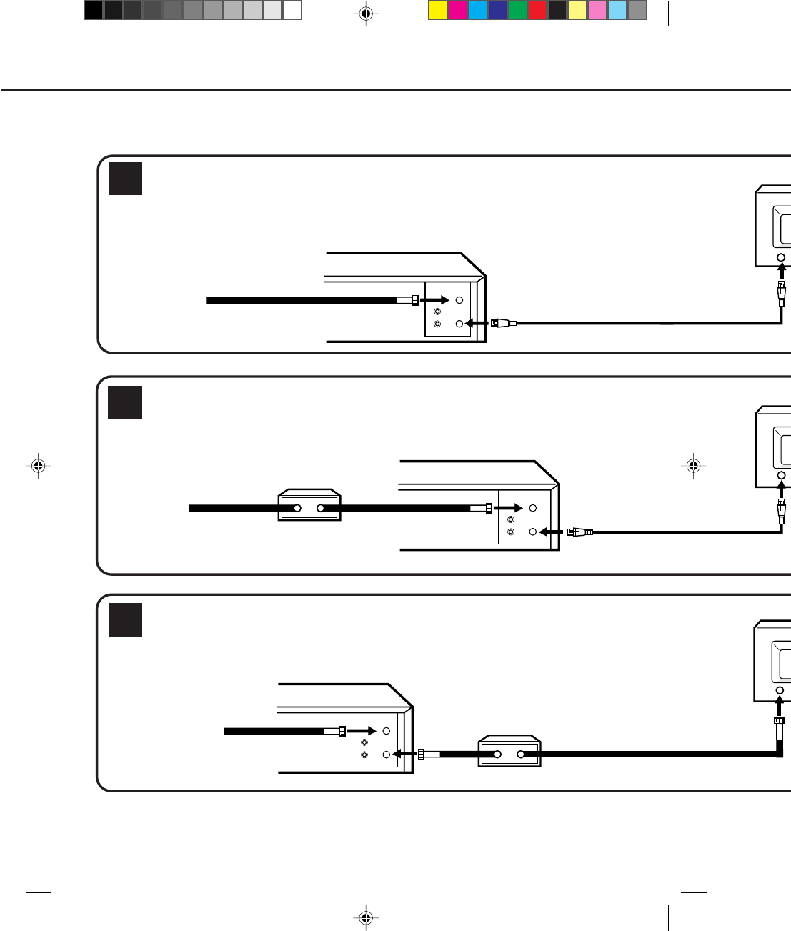
NOTE: IF A VHF OR UHF
ANTENNA IS USED, SET
THE TV/CATV MENU
OPTION TO THE "TV"
MODE.
NOTE: IF A VHF OR UHF
ANTENNA IS USED, SET
THE TV/CATV MENU
OPTION TO THE "TV"
MODE.
UHF
VHF
UHF
VHF
VHF/UHF IN
This VCR has a single 75 ohm output for connection to a TV. If your TV has separate VHF and UHF antenna
inputs (numbers 2 and 3 below), use a splitter to connect the VCR to the TV for VHF and UHF reception.
NOTE: IF A VHF OR UHF
ANTENNA IS USED, SET
THE TV/CATV MENU
OPTION TO THE "TV"
MODE.
TV with single 75 ohm
VHF/UHF antenna input
TV with 300 ohm UHF
and 75 ohm VHF
antenna inputs
TV with 300 ohm UHF
and 300 ohm VHF
antenna inputs
SPLITTER
75 OHM INPUT
75/300 OHM OUTPUTS
(NOT SUPPLIED)
SPLITTER
75 OHM INPUT
300 OHM OUTPUTS
(NOT SUPPLIED)
TV
TV
TV
4C83501A-E(P10-19) 27*10*99, 11:3717
18
MAKE SURE THE TV/CATV MENU OPTION IS SET TO THE "CATV" MODE.
MAKE SURE THE TV/CATV MENU OPTION IS SET TO THE "CATV" MODE.
VHF/UHF
OUT
IN
VHF/UHF
OUT
IN
VHF/UHF
OUT
IN
1
3
2
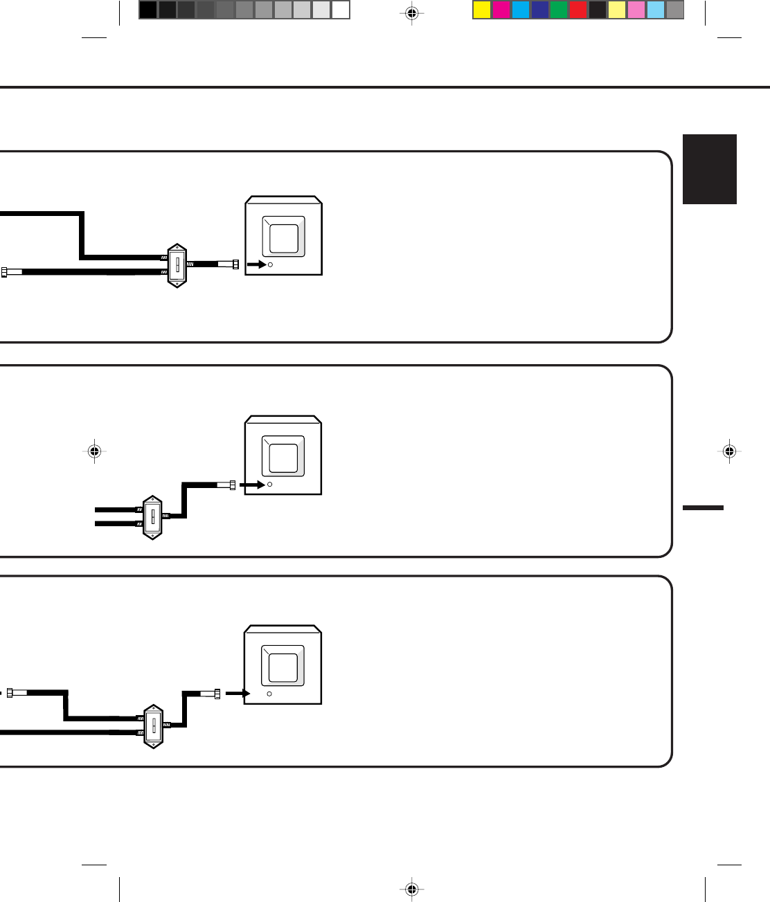
Many cable companies offer services permitting reception of extra channels including pay or subscription channels. This VCR has
an extended tuning range and can be tuned to most cable channels without using a cable company supplied converter box, except
for those channels which are intentionally scrambled. If you subscribe to a special channel which is scrambled, you must have a
descrambler box for proper reception.
IMPORTANT: MAKE SURE THE TV/CATV MENU OPTION IS SET TO THE "CATV" MODE.
IMPORTANT:
IMPORTANT:
WHENEVER A CONVERTER/DESCRAMBLER BOX IS PLACED BEFORE THE VCR, YOU MUST TUNE
THE VCR TO THE OUTPUT OF THE CONVERTER/DESCRAMBLER BOX, USUALLY CHANNEL 3 OR 4.
CATV (CABLE TV) CONNECTIONS
NOTE:
VCR
INCOMING CABLE
CONVERTER/DESCRAMBLER
CONVERTER/DESCRAMBLER
INCOMING CABLE
VCR
INCOMING CABLE
VCR
4C83501A-E(P10-19) 27*10*99, 11:3718
19
ENGLISH
This VCR cannot receive scrambled programs since it does not contain a descrambler. In order to receive scrambled programs,
your existing descrambler must be used. Descrambler boxes are available from cable companies. Consult your local cable
company for more information concerning connection to their descrambler equipment. There are many ways to connect your VCR
to a cable system. Below are six common methods of connection.
Recording of nonscrambled channels.
Use of the programmable timer.
Recording of one channel while watching another.
Recording of channels through the converter box (scrambled and
unscrambled).
Using the programmable timer to record only the channel selected
at the converter box.
Recording one channel while watching another.
Using the VCR tuner to select channels.
To record from converter/descrambler, VCR tuner must be tuned to the
converter output channel, usually channel 3 or 4.
Recording of unscrambled channels
Using the programmable timer.
Recording an unscrambled channel while watching any channel
selected at the converter box.
Recording scrambled channels.
If you are playing a tape or using the tuner built into the VCR, the
converter must be set to the video channel output of the VCR (either 3
or 4).
ALLOWS:
PREVENTS:
NOTE:
ALLOWS:
PREVENTS:
NOTE:
For basic cable service, no premium (scrambled) channels.
ALLOWS:
*
*
*
*
*
*
*
*
*
*
*
TV
VHF/UHF IN
TV
VHF/UHF IN
VHF/UHF IN
TV
4C83501A-E(P10-19) 27*10*99, 11:3719
20
MAKE SURE THE TV/CATV MENU OPTION IS SET TO THE "CATV" MODE.
MAKE SURE THE TV/CATV MENU OPTION IS SET TO THE "CATV" MODE.
OUT
IN
VHF/UHF
VHF/UHF
OUT
IN
VHF/UHF
OUT
IN
A
B
A
B
A
B
6
5
4IMPORTANT: MAKE SURE THE TV/CATV MENU OPTION IS SET TO THE "CATV" MODE.
IMPORTANT:
IMPORTANT:
NOTE: WHENEVER A CONVERTER/DESCRAMBLER BOX IS PLACED BEFORE THE VCR, YOU MUST TUNE
THE VCR TO THE OUTPUT OF THE CONVERTER/DESCRAMBLER BOX, USUALLY CHANNEL 3 OR 4.
CATV (CABLE TV) CONNECTIONS (CONTINUED)
VCR
VCR
SPLITTER
CONVERTER/DESCRAMBLER
INCOMING CABLE
CONVERTER/DESCRAMBLER
INCOMING CABLE
SPLITTER
INCOMING CABLE
SPLITTER
CONVERTER/DESCRAMBLER
CONVERTER/
DESCRAMBLER
VCR
4C83501A-E(P20-29) 27*10*99, 11:3520
21
ENGLISH
A
B
A
B
A
B
Watching scrambled channels while recording another channel.
Using the VCR tuner to select channels.
NOTE:
To record from converter/descrambler, VCR tuner must be tuned to
the converter output channel, usually channel 3 or 4.
Recording of nonscrambled channels.
Recording of one channel while watching another.
Watching premium channels through the converter while recording
nonscrambled channels.
Using the programmable timer.
Recording scrambled channels.
Recording of all channels through the converter box.
Recording a scrambled or unscrambled channel while watching
another (scrambled or unscrambled) channel.
Using the programmable timer to record only the channel selected
at the converter box.
Using the VCR tuner to select channels.
NOTE:
To record from converter/descrambler, VCR tuner must be tuned to
the converter output channel, usually channel 3 or 4.
*
*
*
*
*
ALLOWS:
PREVENTS:
ALLOWS:
PREVENTS:
*
*
*
*
*
ALLOWS:
*
*
*
PREVENTS:
*
YOU MUST TUNE
CHANNEL 3 OR 4.
Recording of all channels through the converter box.
Recording of one channel while watching another.
Using the programmable timer to record only the channel
selected at the converter box.
A/B SWITCH
A/B SWITCH
TV
VHF/UHF IN
TV
A/B SWITCH
VHF/UHF IN
TV
VHF/UHF IN
4C83501A-E(P20-29) 27*10*99, 11:3521
22
OUT
IN
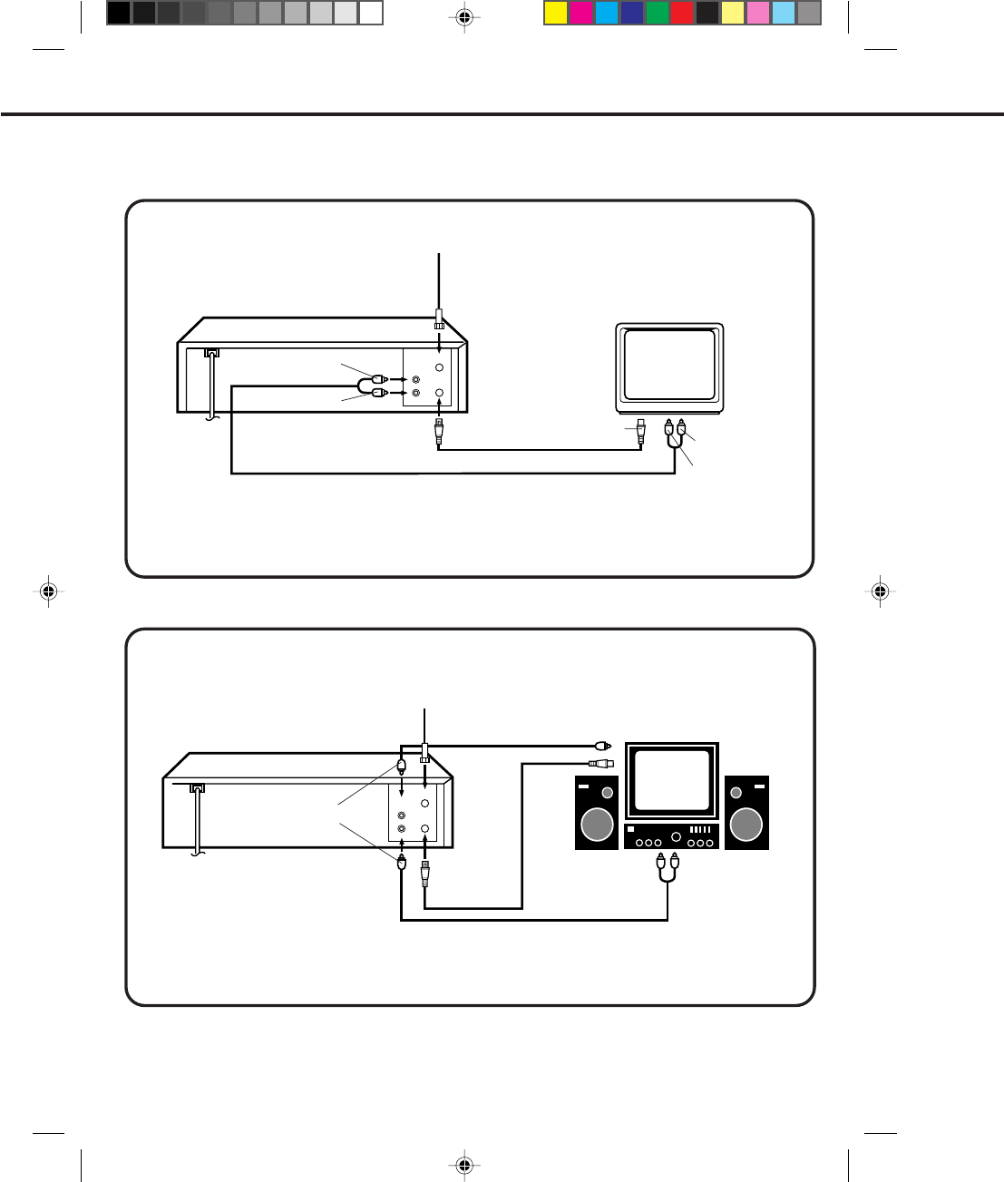
When you connect your VCR to a Stereo Component System, you can view the picture from the VCR while
enjoying powerful sound from your audio system.
NOTE : Sound will be monaural.
AUDIO/VIDEO CONNECTIONS
AUDIO/VIDEO CONNECTION
If your TV has AUDIO IN and VIDEO IN jacks, you can connect your VCR to them to receive a higher quality
picture and sound. If you have a stereo, you can connect a stereo amplifier to enjoy powerful sound.
STEREO AMPLIFIER CONNECTIONS
OUT
IN
TO AUDIO IN
TO ANT IN
TV
VCR
TO VHF/UHF IN
TO VHF/UHF IN
TO VIDEO IN
VIDEO Cord
(Not supplied)
TO ANT IN
TO VHF/UHF
OUT
TV
VCR
Connect the AUDIO OUT jack on the VCR to the AUX jacks on the stereo amplifier.
1. Connect the VIDEO OUT jack on the VCR to the VIDEO IN jack on the TV.
2. Connect the AUDIO OUT jack on the VCR to the AUDIO IN jacks on the TV.
3. Set the VIDEO/TV selector of your TV to "VIDEO".
AUDIO Cord (Not supplied)
TO AUDIO OUT
TO VIDEO OUT
TO AUX (R) IN
TO AUX (L) IN
TO AUDIO OUT
TO VIDEO OUT
AUDIO/VIDEO Cord (Not supplied)
TO VHF/UHF
OUT
TO VIDEO IN
4C83501A-E(P20-29) 27*10*99, 11:3522
23
ENGLISH
POWER EJECT
TV/VCR
COUNTER RESET
INPUT SELECT
REC/OTR
SLOW
SPEED
MENU
–+
–
+
SET
SKIP
SEARCH CLOCK/
COUNTER
–+
TRACKING
AUTO
CANCEL
ENTER
STOP
PLAY
F.FWD
REW
TIMER REC
PAUSE/STILL
CHANNEL
CALL
1
2
3
456
78
0
9
Press the TV/VCR selector button to select the
VCR position.
SETTING THE VIDEO CHANNEL
1
4
23
When a TV is connected with an antenna cable only.
5Select any channel to receive a TV station in
your area.
Turn ON the VCR POWER
button.
Set the 3/4 Channel
selector switch (Rear of the
VCR) to CH 3 or 4.
Turn ON the TV and set to
CH 3 or 4 to correspond
with the channel selected
in .
2
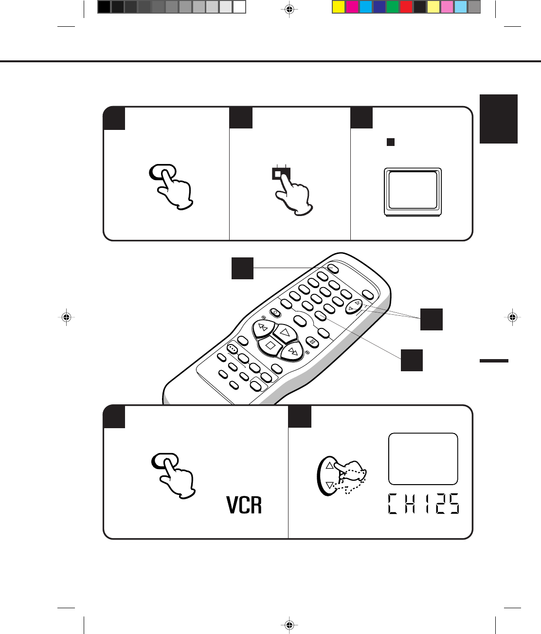
To view playback of a recorded tape, or to watch a program selected by the VCR's channel selector, the TV
must be set to channel 3 or 4 (video channel).
3
OR
4
The channel number will appear on the screen and
display about 4 seconds.The VCR indicator will light in the display.
For a push-button TV tuner
If CH 3 or 4 corresponding to the video channel cannot be tuned on your TV, proceed as follows: set the VCR 3/4
channel selector and the TV to CH 3 or 4, play back a prerecorded tape and tune the TV to receive a sharp color
picture from the video cassette recorder. Refer to your TV owner's manual for details.
CH 125
CH 125
TV/VCR
POWER CH
3 4
CHANNEL
5
4
1
4C83501A-E(P20-29) 27*10*99, 11:3523
24
POWER EJECT
TV/VCR
COUNTER RESET
INPUT SELECT
REC/OTR
SLOW
SPEED
MENU
–+
–
+
SET
SKIP
SEARCH CLOCK/
COUNTER
–+
TRACKING
AUTO
CANCEL
ENTER
STOP
PLAY
F.FWD
REW
TIMER REC
PAUSE/STILL
CHANNEL
CALL
1
2
3
456
78
0
9
This VCR can display on the TV screen in the English, Spanish or French languages.
2 3
CHECK BEFORE YOU BEGIN
• Turn ON the TV and set to the video channel 3 or 4.
• Turn ON the VCR POWER button.
• Press the TV/VCR selector button to select the VCR
mode.
When a TV is connected with an audio/video cable,
turn the TV and this VCR on and select the video
input mode on the TV.
Press the SET + or – button to select the desired
language: English, Spanish or French.
Press the MENU button until the MENU screen
is cleared.
ON-SCREEN LANGUAGE SELECTION
1
〈
+/–/ENTER/MENU
〉
LANGUAGE/IDIOMA/LANGUE
ENGLISH
FRANCAIS
ESPAÑOL
1
〈
+/–/ENTER/MENU
〉
MENU
CLOOK SET
TIMER REC SET
AUTO REPEAT
CH SET UP
LANGUAGE/IDIOMA/LANGUE
NO NOISE BACKGROUND
ON OFF
ON OFF
Press the MENU button.
Press the SET + or – button to select the
LANGUAGE option, then press the ENTER
button.
ENTERMENU – SET +
– SET + MENU
2
1 3
4C83501A-E(P20-29) 27*10*99, 11:3524
25
ENGLISH
POWER EJECT
TV/VCR
COUNTER RESET
INPUT SELECT
REC/OTR
SLOW
SPEED
MENU
–+
–
+
SET
SKIP
SEARCH CLOCK/
COUNTER
–+
TRACKING
AUTO
CANCEL
ENTER
STOP
PLAY
F.FWD
REW
TIMER REC
PAUSE/STILL
CHANNEL
CALL
1
2
3
456
78
0
9
EXAMPLE: Setting the clock to "8:30 AM" March, 23 (THU), 2000.
2
• After a power failure or disconnection of the power, the timer settings will be lost. In this case, reset the
present time.
• Press the CANCEL button to move cursor backward for correction.
• If you want to corret time or date while the clock is functioning, press the MENU button, then press
SET + or – button to select the CLOCK SET option, then press the ENTER button.
To make any adjustments perform steps 2 through 3.
3
〈
+/–/ENTER/CANCEL/MENU
〉
MONTH
DAY
TIME
YEAR
3
1
12
(WED)
: 00 AM
2000
SETTING THE CLOCK
CHECK BEFORE YOU BEGIN
• Turn ON the TV and set to the video channel 3 or 4.
• Turn ON the VCR POWER button.
• Press the TV/VCR selector button to select the VCR mode.
When a TV is connected with an audio/video cable,
turn the TV and this VCR on, and select the video input
mode on the TV.
Press the SET + or – button to set the month,
then press the ENTER button.
Set the day, year and time as in Step 2.
• The day of the week will automatically appear
when you set the year.
• Press and hold down the button to increase/
decrease the minute by 10.
• Auto date and time start functioning when
you finish setting.
NOTE:
1 2
ENTER
〈
+/–/ENTER/CANCEL/MENU
〉
MONTH
DAY
TIME
YEAR
3
23
8
(THU)
: 30 AM
2000
Press the MENU button. Press the SET + or –
button to select the CLOCK SET option, then
press the ENTER button.
1
〈
+/–/ENTER/MENU
〉
MENU
CLOOK SET
TIMER REC SET
AUTO REPEAT
CH SET UP
LANGUAGE/IDIOMA/LANGUE
NO NOISE BACKGROUND
ON OFF
ON OFF
MENU – SET + ENTER
3
1
– SET + ENTER
– SET +
4C83501A-E(P20-29) 27*10*99, 11:3525
26
POWER EJECT
TV/VCR
COUNTER RESET
INPUT SELECT
REC/OTR
SLOW
SPEED
MENU
–+
–
+
SET
SKIP
SEARCH CLOCK/
COUNTER
–+
TRACKING
AUTO
CANCEL
ENTER
STOP
PLAY
F.FWD
REW
TIMER REC
PAUSE/STILL
CHANNEL
CALL
1
2
3
456
78
0
9
2
3
1
5
4
SETTING THE CHANNELS
This VCR is equipped with a channel memory feature which allows channels to skip up or down to the next
channel set into memory, skipping over unwanted channels. Before selecting channels, they must be programmed
into the VCR’s memory. In addition to normal VHF and UHF channels, this VCR can receive up to 113 Cable TV
channels. To use this VCR with an antenna, set the TV/CATV menu option to the TV mode. When shipped from the
factory, this menu option is in the CATV mode.
Press the MENU button. Press the SET + or – button to select the
CH SET UP option, then press the ENTER button.
Press the SET + or – button
to select the TV/CATV mode.
Press the ENTER button to
select the TV or CATV mode.
The arrow indicates the
selected mode.
Press the MENU button
twice to return to normal TV
viewing.
〈
+/–/ENTER/MENU
〉
MENU
CLOOK SET
TIMER REC SET
AUTO REPEAT
CH SET UP
LANGUAGE/IDIOMA/LANGUE
NO NOISE BACKGROUND
ON OFF
ON OFF
〈
+/–/ENTER/MENU
〉
CH SET UP
TV CATV
AUTO CH MEMORY
ADD/DELETE
TV/CATV SELECTION
2
ENTER MENU
– SET +
– SET + ENTER
TV - VHF/UHF channels
CATV - CABLE TV channels
MENU
1 5 4
3
4C83501A-E(P20-29) 27*10*99, 11:3526
27
ENGLISH
POWER EJECT
TV/VCR
COUNTER RESET
INPUT SELECT
REC/OTR
SLOW
SPEED
MENU
–+
–
+
SET
SKIP
SEARCH CLOCK/
COUNTER
–+
TRACKING
AUTO
CANCEL
ENTER
STOP
PLAY
F.FWD
REW
TIMER REC
PAUSE/STILL
CHANNEL
CALL
1
2
3
456
78
0
9
5
CHECK BEFORE YOU BEGIN
• Turn ON the TV and set to the video channel 3 or 4.
• Turn ON the VCR POWER button.
• Press the TV/VCR selector button to select the VCR
mode.
When a TV is connected with an audio/video cable,
turn the TV and this VCR on, and select the video
input mode on the TV.
1
〈
+/–/ENTER/MENU
〉
CH SET UP
TV CATV
AUTO CH MEMORY
ADD/DELETE
Press the MENU button.
Press the SET + or – button to select the CH
SET UP option, then press the ENTER button.
Press the SET + or – button to select the AUTO
CH MEMORY mode, then press the ENTER
button.
The auto tuning will start. The channel display
will count up and when finished, the screen
returns to normal.
CH 001
23
The VCR can receive a maximum of 181 channels by presetting the channels into memory.
AUTOMATIC MEMORY TUNING
CH 001
– SET + ENTER
MENU – SET + ENTER
〈
+/–/ENTER/MENU
〉
MENU
CLOOK SET
TIMER REC SET
AUTO REPEAT
CH SET UP
LANGUAGE/IDIOMA/LANGUE
NO NOISE BACKGROUND
ON OFF
ON OFF
1 2
1
4C83501A-E(P20-29) 27*10*99, 11:3627
28
POWER EJECT
TV/VCR
COUNTER RESET
INPUT SELECT
REC/OTR
SLOW
SPEED
MENU
–+
–
+
SET
SKIP
SEARCH CLOCK/
COUNTER
–+
TRACKING
AUTO
CANCEL
ENTER
STOP
PLAY
F.FWD
REW
TIMER REC
PAUSE/STILL
CHANNEL
CALL
1
2
3
456
78
0
9
〈
+
/
–
/ENTER/MENU
〉
MENU
CLOOK SET
TIMER REC SET
AUTO REPEAT
CH SET UP
LANGUAGE/IDIOMA/LANGUE
NO NOISE BACKGROUND
ON OFF
ON OFF
45
123
– SET + ENTER– SET +
〈
+/–/ENTER/MENU
〉
CH SET UP
AUTO CH MEMORY
ADD/DELETE
TV CATV
MENU
TO ADD/DELETE CHANNELS
Press the ENTER button if you wish to DELETE
the channel from memory.
Press the ENTER button if you wish to ADD the
unmemorized channel.
Repeat Steps 3 and 4 for each channel to be added or
deleted.
Press the MENU button three times after adding
or deleting all of the desired channels, to return
to normal TV viewing.
〈
+/–/ENTER/MENU
〉
ADD CH 002
Press the MENU button.
Press the SET + or – button to
select the CH SET UP option,
then press the ENTER button.
Press the SET + or – button
to select the ADD/DELETE
mode, then press the
ENTER button.
Select the desired channels
to be memorized or deleted
using the SET + or – button.
SETTING THE CHANNELS (CONTINUED)
1 2
ENTER – SET +
MENU
ENTER
1 5
3
4
4C83501A-E(P20-29) 27*10*99, 11:3628
29
ENGLISH
POWER EJECT
TV/VCR
COUNTER RESET
INPUT SELECT
REC/OTR
SLOW
SPEED
MENU
–+
–
+
SET
SKIP
SEARCH CLOCK/
COUNTER
–+
TRACKING
AUTO
CANCEL
ENTER
STOP
PLAY
F.FWD
REW
TIMER REC
PAUSE/STILL
CHANNEL
CALL
1
2
3
456
78
0
9
1
2
CHECK BEFORE YOU BEGIN
• Turn ON the TV and set to the video channel 3 or 4.
• Turn ON the VCR POWER button.
• Press the TV/VCR selector button to select the
VCR mode.
When a TV is connected with an audio/video cable,
turn the TV and this VCR on and select the video
input mode on the TV.
NOISE ELIMINATION (BLUE SCREEN)
3
〈
+/–/ENTER/MENU
〉
MENU
CLOOK SET
TIMER REC SET
AUTO REPEAT
CH SET UP
LANGUAGE/IDIOMA/LANGUE
NO NOISE BACKGROUND
ON OFF
ON OFF
Press the MENU button until the MENU screen
is cleared.
Press the ENTER button to select the ON position.
When you don't want to receive a weak signal broadcast, the Blue back screen can be obtained by selecting
the NO NOISE BACKGROUND "ON". When the unit is shipped from the factory, the NO NOISE
BACKGROUND is set to the "ON".
Press the MENU button, then press the SET + or
– button to select the NO NOISE BACKGROUND
option.
MENU
〈
+/–/ENTER/MENU
〉
MENU
CLOOK SET
TIMER REC SET
AUTO REPEAT
CH SET UP
LANGUAGE/IDIOMA/LANGUE
NO NOISE BACKGROUND
ON OFF
ON OFF
ENTER
– SET +
MENU
1
1 3 2
4C83501A-E(P20-29) 27*10*99, 11:3629
30
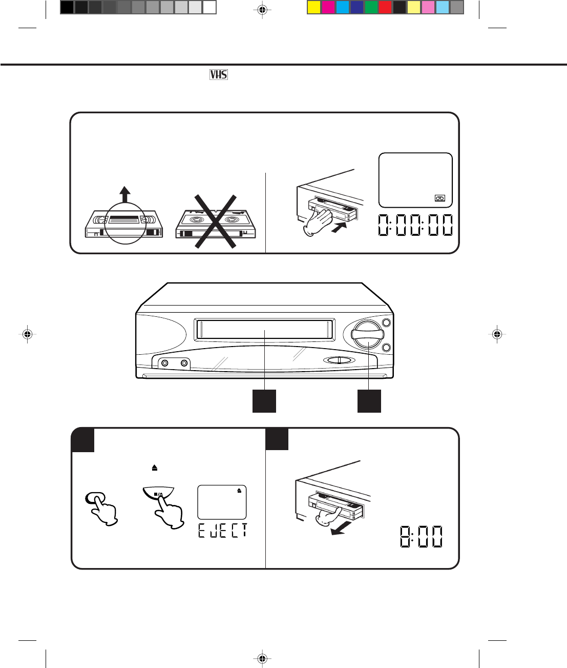
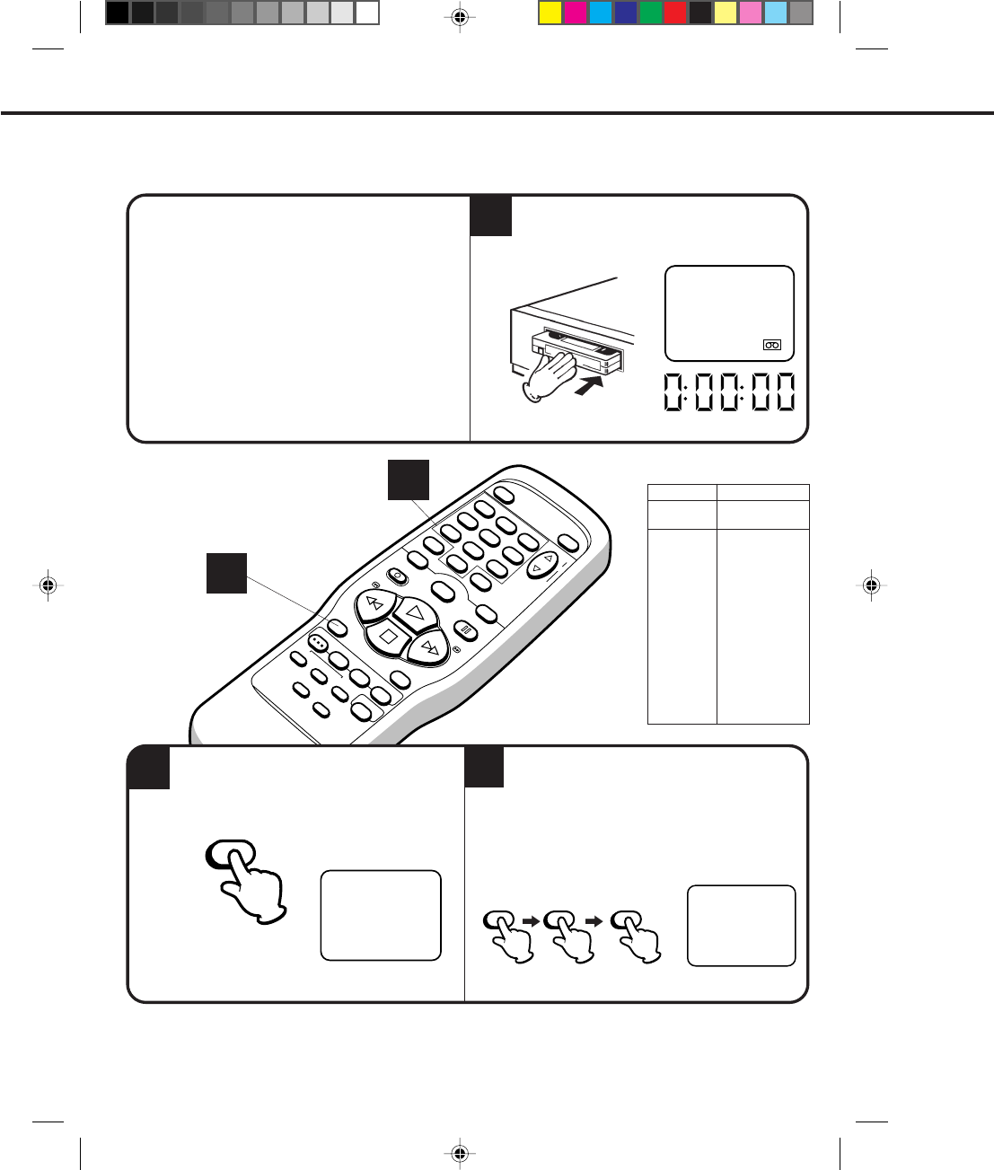
LOADING
UNLOADING
12
NOTE:
Use only video cassette tapes marked .
LOADING AND UNLOADING VIDEO CASSETTE TAPES
The clock display will change to the counter display.
Push the center of the tape until it is automatically retracted.
AUTOMATIC POWER ON
The VCR will turn on automatically and the POWER indicator will light.
AUTOMATIC PLAY
When loading a cassette tape without the erase prevention tab, playback will start immediately.
Insert the cassette with its labeled side facing you.
An inverted cassette cannot be inserted.
To unload a cassette, press the EJECT button on
the remote control, or press the STOP/EJECT
button on the VCR twice. The first press will stop
the tape in any mode. The second press will eject
the tape. The " " will appear on the screen.
The EJECT indicator will light in the display.
AUTOMATIC EJECT
If the VCR automatically rewinds the tape to the
beginning (AUTO REWIND FEATURE), the tape will
be ejected automatically (See the NOTE on page 37).
Pull the cassette out.
The counter display will change to the clock display.
Always eject the tape when not in use.
The cassette can be ejected even if the POWER switch is "OFF".
•
•
12
EJECT
OR
STOP/EJECT
4C83501A-E(P30-37) 27*10*99, 10:5630
31
ENGLISH
POWER EJECT
TV/VCR
COUNTER RESET
INPUT SELECT
REC/OTR
SLOW
SPEED
MENU
–+
–
+
SET
SKIP
SEARCH CLOCK/
COUNTER
–+
TRACKING
AUTO
CANCEL
ENTER
STOP
PLAY
F.FWD
REW
TIMER REC
PAUSE/STILL
CHANNEL
CALL
1
2
3
456
78
0
9
TO START PLAYBACK
To play a prerecorded cassette tape.
1
PLAYBACK
TO STOP PLAYBACK
CHECK BEFORE YOU BEGIN
Turn ON the TV and set to the video channel 3 or 4.
When a TV is connected with an audio/video cable,
turn the TV and this VCR on and select the video
input mode on the TV.
The clock display will change in the counter display.
Press the PLAY button. Playback will start.
Load a prerecorded tape. (When loading a
cassette tape without the erase prevention tab,
playback will start automatically.)
Press the STOP button once. The tape will stop but
remain fully loaded and ready to play.
The " " will appear on the screen about 4 seconds.
The PLAY indicator will light in the display about 4 second.
The " " will appear on the screen about 4 seconds.
The STOP indicator will light in the display about 4 second.
TAPES
PLAY
STOP
2
2
4C83501A-E(P30-37) 27*10*99, 10:5631
32
POWER EJECT
TV/VCR
COUNTER RESET
INPUT SELECT
REC/OTR
SLOW
SPEED
MENU
–+
–
+
SET
SKIP
SEARCH CLOCK/
COUNTER
–+
TRACKING
AUTO
CANCEL
ENTER
STOP
PLAY
F.FWD
REW
TIMER REC
PAUSE/STILL
CHANNEL
CALL
1
2
3
456
78
0
9
The " " will appear on the screen and display about
4 seconds.
The F.FWD indicator will light in the display about 4 second.
DIGITAL TRACKING CONTROL
FORWARD/REVERSE PICTURE SEARCH
If you want to see the tape program during REW (F.FWD) mode, press and hold the REW (F.FWD) button again.
The backward (forward) visual search picture will be seen on the screen. Release to return to the REW (F.FWD)
mode.
TO REWIND OR FORWARD THE TAPE RAPIDLY
When a tape is played, the Digital Auto Tracking System automatically adjusts the tracking to obtain the best
possible picture. If noise bars appear during playback, adjust the tracking manually:
•Press the Manual TRACKING + or – button to obtain the best possible picture. To resume automatic
tracking, press the AUTO Tracking button.
PLAYBACK (CONTINUED)
The " " will appear on the screen and display about
4 seconds.
The REW indicator will light in the display about 4 second.
Press the REW button in the STOP mode. Press the F.FWD button in the STOP mode.
F.FWD
REW
AUTO TRACKING
AUTO TRACKING
4C83501A-E(P30-37) 27*10*99, 10:5632
33
ENGLISH
POWER EJECT
TV/VCR
COUNTER RESET
INPUT SELECT
REC/OTR
SLOW
SPEED
MENU
–+
–
+
SET
SKIP
SEARCH CLOCK/
COUNTER
–+
TRACKING
AUTO
CANCEL
ENTER
STOP
PLAY
F.FWD
REW
TIMER REC
PAUSE/STILL
CHANNEL
CALL
1
2
3
456
78
0
9
SKIP
SEARCH
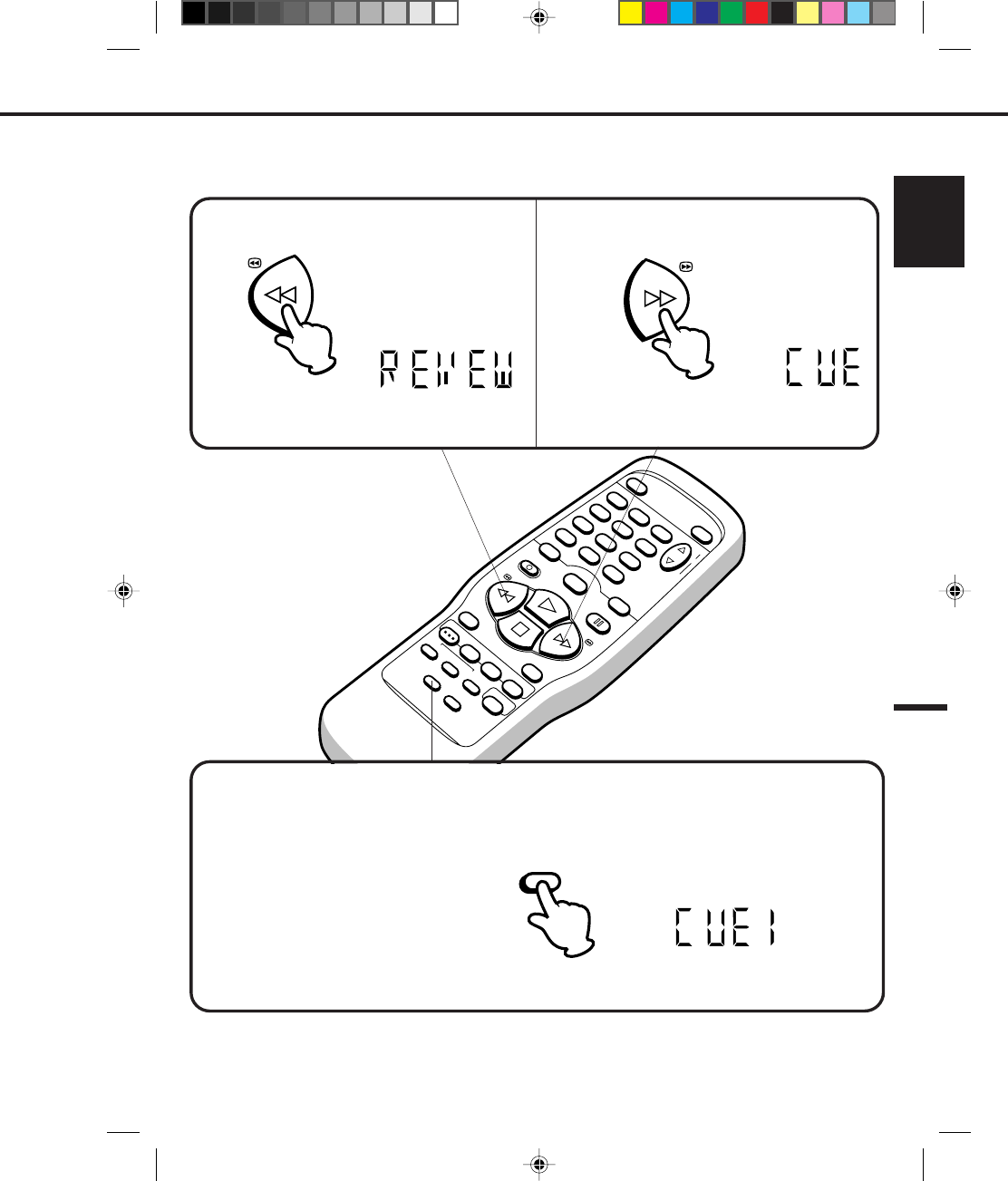
To visually search backward, press the REW button
once or twice in the PLAYBACK mode.
To visually search forward, press the F.FWD button
once or twice in the PLAYBACK mode.
SPECIAL PLAYBACK
•
•
•
•
NOTE:
TO VISUALLY SEARCH FOR DESIRED POINTS
When either the F.FWD or REW button is pressed in the PLAYBACK mode, the speed search picture will appear.
When pressed twice, the search picture will increase speed. Speed search time depends upon the speed used
(SP, LP or SLP) during recording. To rewind or fast forward a tape, press the STOP button, and then press the REW
or F.FWD button.
The REVEW indicator will light in the display about
4 seconds.
Press the PLAY button to resume normal viewing speed.
The CUE indicator will light in the display about
4 seconds.
Press the PLAY button to resume normal viewing speed.
Best results during speed search playback can be obtained with cassette tapes recorded in the "SLP" mode.
A few noise bars will appear on the picture
during SPEED SEARCH and STILL.
The audio output is muted
during special playback.
To prevent damage to the tape,
special playback
is automatically changed to the PLAYBACK mode after 5 minutes.
33
SKIP SEARCH
Press the SKIP SEARCH button in the PLAY mode. The VCR will search forward through approximately 30
seconds of the tape (e.g. unwanted commercial time) for each press of the SKIP SEARCH button (maximum
six presses) and then resume normal playback. The number of presses will appear on the display in place of
the channel number.
For example: 1 press: 30 seconds of tape
2 presses: 60 seconds of tape
3 presses: 90 seconds of tape
The CUE 1 indicator will light in the
display. (For example : 1 press.)
REW
F.FWD
4C83501A-E(P30-37) 27*10*99, 10:5733
34
POWER EJECT
TV/VCR
COUNTER RESET
INPUT SELECT
REC/OTR
SLOW
SPEED
MENU
–+
–
+
SET
SKIP
SEARCH CLOCK/
COUNTER
–+
TRACKING
AUTO
CANCEL
ENTER
STOP
PLAY
F.FWD
REW
TIMER REC
PAUSE/STILL
CHANNEL
CALL
1
2
3
456
78
0
9
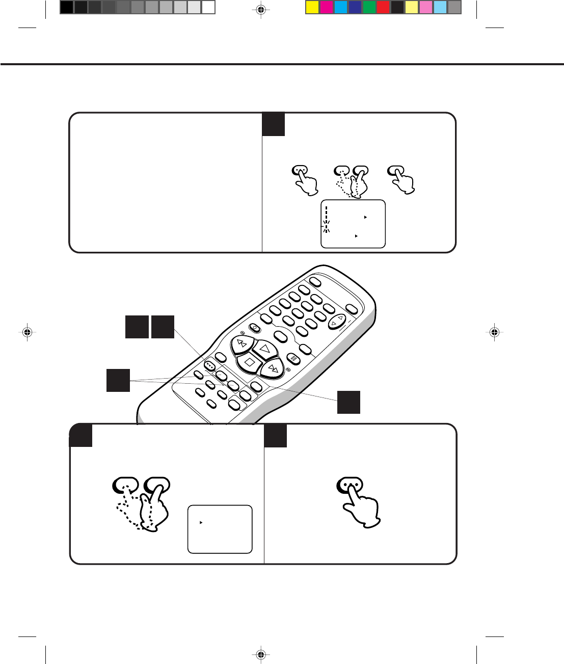
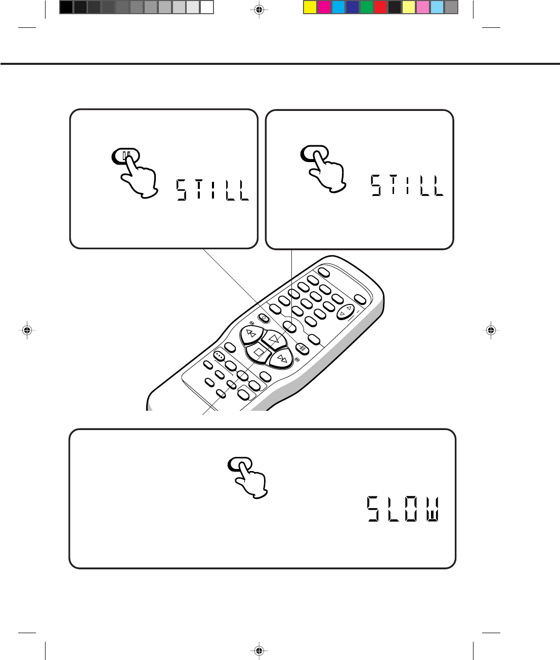
SLOW MOTION PLAYBACK
Press the SLOW button in the PLAYBACK mode. Playback will proceed at 1/10th of the normal speed.
The SLOW indicator will light in the display about 4 seconds.
Press the PLAY button again to resume normal playback.
NOTE: SLOW TRACKING AND VERTICAL LOCK ADJUSTMENT
If noise bars appear in the picture during slow motion, press the Manual TRACKING + or – button to reduce the
noise bars.
If the still picture jitters excessively, press the Manual TRACKING + or – button to stabilize the still picture.
SPECIAL PLAYBACK (CONTINUED)
Press the SLOW button during STILL playback.
The still picture will advance by one frame each time
you press the button. Hold the button for continuous
frame by frame viewing.
Press the PAUSE/STILL button or PLAY button to
resume normal playback.
FRAME BY FRAME ADVANCE
Press the PAUSE/STILL button in the PLAYBACK
mode.
TO WATCH A STILL PICTURE
The STILL indicator will light in the display about
4 seconds.
Press the PAUSE/STILL button or PLAY button to
resume normal playback.
SLOW
PAUSE/STILL
SLOW
4C83501A-E(P30-37) 27*10*99, 10:5734
35
ENGLISH
POWER EJECT
TV/VCR
COUNTER RESET
INPUT SELECT
REC/OTR
SLOW
SPEED
MENU
–+
–
+
SET
SKIP
SEARCH CLOCK/
COUNTER
–+
TRACKING
AUTO
CANCEL
ENTER
STOP
PLAY
F.FWD
REW
TIMER REC
PAUSE/STILL
CHANNEL
CALL
1
2
3
456
78
0
9
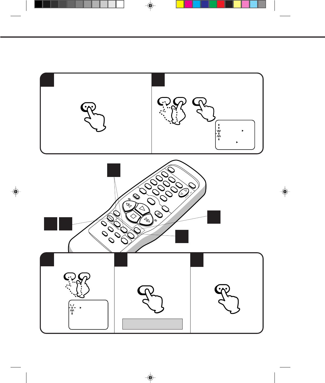
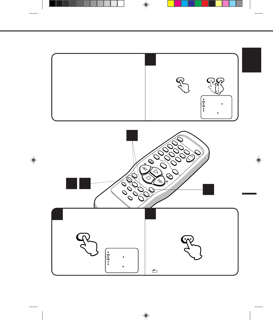
TO WATCH A TAPE REPEATEDLY
NOTE:
Press the ENTER button to select the ON
position.
2
To cancel repeat mode, follow the above steps 1 and 2, then press the ENTER button to select the OFF
position. Press the MENU button to return to the TV.
Press the MENU button.
If you press the PLAY button, the tape will play
over and over until the repeat mode is canceled.
3
" " will appear when you press the CALL button.
CHECK BEFORE YOU BEGIN
• Turn ON the TV and set to the video channel 3 or 4.
• Turn ON the VCR POWER button.
• Press the TV/VCR selector button to select the VCR mode.
When a TV is connected with an audio/video cable,
turn the TV and this VCR on, and select the video
input mode on the TV.
MENU
ENTER
1Press the MENU button.
Then press the SET + or – button to select the
AUTO REPEAT option.
〈
+/–/ENTER/MENU
〉
MENU
CLOOK SET
TIMER REC SET
AUTO REPEAT
CH SET UP
LANGUAGE/IDIOMA/LANGUE
NO NOISE BACKGROUND
ON OFF
ON OFF
– SET +
MENU
〈
+/–/ENTER/MENU
〉
MENU
CLOOK SET
TIMER REC SET
AUTO REPEAT
CH SET UP
LANGUAGE/IDIOMA/LANGUE
NO NOISE BACKGROUND
ON OFF
ON OFF
1 3 2
1
4C83501A-E(P30-37) 27*10*99, 10:5735
36
POWER EJECT
TV/VCR
COUNTER RESET
INPUT SELECT
REC/OTR
SLOW
SPEED
MENU
–+
–
+
SET
SKIP
SEARCH CLOCK/
COUNTER
–+
TRACKING
AUTO
CANCEL
ENTER
STOP
PLAY
F.FWD
REW
TIMER REC
PAUSE/STILL
CHANNEL
CALL
1
2
3
456
78
0
9
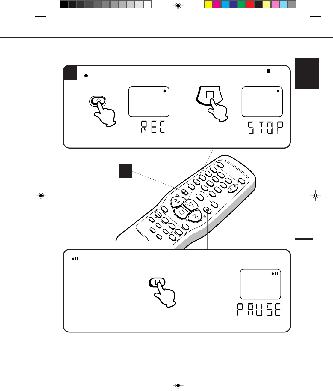
RECORDING A TV PROGRAM
RECORDING AND VIEWING THE SAME TV PROGRAM
NOTE: Since the VCR has its own TV tuner, it is not actually necessary to have the TV turned on in order to make
a recording. Turning on the TV merely allows confirmation of the proper channel settings on your VCR.
1
CHECK BEFORE YOU BEGIN
• Turn ON the TV and set to the video channel 3 or 4.
• Turn ON the VCR POWER button.
• Press the TV/VCR selector button to select the
VCR mode.
When a TV is connected with an audio/video cable,
turn the TV and this VCR on and select the video
input mode on the TV.
Press the direct channel selection buttons to
select the channel to be recorded.
1-9
10-19
20-99
100-125
Press 0 twice and then 1-9 as required.
(Example; to select 2, press 002.)
Press 0 first and then the remaining 2
digits in order from left to right.
(Example; press 018 for 18.)
Press 2 digits in order. (Example; press
22 for 22.)
Press the 3 digits in order. (Example;
press 110 for 110.)
3
Press the SPEED selector button to select the
desired tape speed SP, LP or SLP.
Load a cassette tape with the erase
prevention tab intact.
The VCR will automatically turn on.
The counter and SP, LP or SLP will appear on the
screen about 4 seconds.
2
VHF/UHF/CATV CHANNELS
UHF
14-69 STD/HRC/IRC
14-36
(A) (W)
37-59
(AA) (WW)
60-85
(AAA) (ZZZ)
86-94
(86) (94)
95-99
(A-5) (A-1)
100-125
(100)(125)
01
(5A)
TV CATV
VHF
2-13 VHF
2-13
The clock display will change in the counter display.
CH 110
00 : 00 : 00 SP
Or press the CHANNEL ▲ or ▼ button to select the
channel to be recorded.
3
SPEED
2
110
4C83501A-E(P30-37) 27*10*99, 10:5736
37
ENGLISH
POWER EJECT
TV/VCR
COUNTER RESET
INPUT SELECT
REC/OTR
SLOW
SPEED
MENU
–+
–
+
SET
SKIP
SEARCH CLOCK/
COUNTER
–+
TRACKING
AUTO
CANCEL
ENTER
STOP
PLAY
F.FWD
REW
TIMER REC
PAUSE/STILL
CHANNEL
CALL
1
2
3
456
78
0
9
4
NOTE:
Press the REC/OTR button.
" " will appear on the screen about 4
seconds.
Press the PAUSE/STILL button to avoid recording unwanted material. Press again to continue the recording.
" " will appear on screen about 4 seconds and the REC indicator will light in the display to continue
pause mode.
Press the STOP button to stop recording. " " will
appear on screen about 4 seconds.
TO STOP RECORDING
AUTO REWIND FEATURE
This VCR will automatically rewind the tape when the tape has ended (except during OTR and TIMER REC). It will also
eject the tape and turn the VCR’s power OFF.
NOTE: The pause function will be released after 5 minutes to prevent damage to the tape or the VCR. The
VCR will change to the STOP mode.
TO STOP RECORDING TEMPORARILY
The STOP indicator will light in the display about
4 seconds.
CH 110
PAUSE/STILL
STOP
REC/OTR
4
4C83501A-E(P30-37) 27*10*99, 10:5737
38
While the VCR is recording, press the TV/VCR
selector button to select the TV position.
The TV/VCR indicator will go off and recording
will continue.
Select the TV channel you want to watch by
using the TV channel selector.
RECORDING ONE PROGRAM WHILE WATCHING ANOTHER
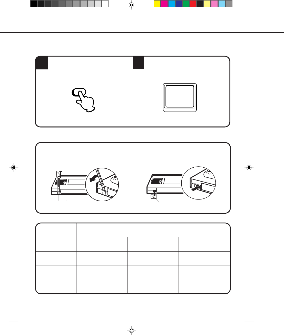
After recording, break off the erase prevention
tab if you do not wish to record over the tape.
Cover the hole with adhesive tape.
Be careful the tape does not extend past the edges
of the cassette housing.
TAPE SPEED AND MAXIMUM RECORDING/PLAYBACK TIME
TAPE SPEED
SP
(Standard Play)
LP
(Long Play)
SLP
(Super Long Play)
VIDEO CASSETTE TAPE
Erase prevention tab Adhesive tape
NOTE: Some CATV hookups do not permit viewing one channel while recording another. See pages 18-21.
1 hour
30 minutes
1-1/2 hours
1 hour
2 hours
3 hours
1-1/2 hours
4-1/2 hours
3 hours
T-90
6 hours
4 hours
2 hours
5-1/3 hours
2-2/3 hours
7 hours
10-1/2 hours
3-1/2 hours
T-210 T-160 T-120 T-60 T-30
8 hours
RECORDING A TV PROGRAM (CONTINUED)
TV/VCR
TO RECORD AGAIN
TO PREVENT AN ACCIDENTAL RECORDING
12
4C83501A-E(P30-37) 27*10*99, 10:5738

38
4C83501A-E(P38-43) 27*10*99, 10:5538
39
ENGLISH
POWER EJECT
TV/VCR
COUNTER RESET
INPUT SELECT
REC/OTR
SLOW
SPEED
MENU
–+
–
+
SET
SKIP
SEARCH CLOCK/
COUNTER
–+
TRACKING
AUTO
CANCEL
ENTER
STOP
PLAY
F.FWD
REW
TIMER REC
PAUSE/STILL
CHANNEL
CALL
1
2
3
456
78
0
9
00 : 00 : 00 SP
EXAMPLE: One-touch timer recording for 30 minutes.
ONE-TOUCH TIMER RECORDING (OTR)
The one-touch timer recording feature provides a simple and convenient way to make a timed recording.
To cancel OTR, press the STOP button or turn off the power.
•
•
2
1
CHECK BEFORE YOU BEGIN
• Turn ON the TV and set to the
video channel 3 or 4.
• Turn on the VCR power button.
When a TV is connected with an
audio/video cable, turn the TV on
and select the video input mode on
the TV.
4
3
NOTE: Press the REC/OTR button to increase the time needed for recording. (See the chart below.)
Press
Recording time
4 times
1:30
5 times
2:00
6 times
3:00
7 times
4:00
3 times
1:00
twice
0:30
once
NORMAL REC
9 times
NORMAL REC
8 times
5:00
Press the REC/OTR button to begin recording.
Press the button again to stop recording after
30 minutes. Each additional press of the REC/
OTR button will increase recording time as shown in
the chart below, up to a maximum of 5 hours. The
OTR and recording time will appear on screen about
4 seconds.
Load a cassette tape with the
erase prevention tab intact. Press the SPEED selector
button to select the desired
tape speed SP, LP or SLP.
The counter and SP, LP or SLP
will appear on the screen about 4
seconds.
Press the CHANNEL ▲ or ▼ button to select
the channel to be recorded.
The channel number will appear on the screen and
display about 4 seconds.
The clock display will change in the
counter display.
CH 125
CH 125
OTR 0 : 30
SPEED
REC/OTR
2
4
3
CHANNEL
4C83501A-E(P38-43) 27*10*99, 10:5539
40
POWER EJECT
TV/VCR
COUNTER RESET
INPUT SELECT
REC/OTR
SLOW
SPEED
MENU
–+
–
+
SET
SKIP
SEARCH CLOCK/
COUNTER
–+
TRACKING
AUTO
CANCEL
ENTER
STOP
PLAY
F.FWD
REW
TIMER REC
PAUSE/STILL
CHANNEL
CALL
1
2
3
456
78
0
9
---
-:-- -:--
-:-- ---
-:-- -:-- ---
-:-- -:-- ---
-:-- -:-- ---
-:-- -:-- ---
-:-- -:-- ---
-:-- -:-- ---
------ -
------ -
------
26(SU)
12:34
AM
-
-
------ -
------ -
------ -
------ -
〈
+/-/ENTER/CANCEL/MENU
〉
START
END
DATE CH
---
-:--
-:-- -:--
-:-- ---
-:-- -:-- ---
-:-- -:-- ---
-:-- -:-- ---
-:-- -:-- ---
-:-- -:-- ---
-:-- -:-- ---
------ -
------ -
------
------ -
-
------ -
------ -
------ -
------ -
〈
+/–/ENTER/CANCEL/MENU
〉
START
END
DATE CH
Press the MENU button. Check the TIMER REC
SET option is selected, then press the ENTER
button.
〈
+/–/ENTER/MENU
〉
MENU
CLOOK SET
TIMER REC SET
AUTO REPEAT
CH SET UP
LANGUAGE/IDIOMA/LANGUE
NO NOISE BACKGROUND
ON OFF
ON OFF
Timer recording can be programmed on-screen with the remote control. The built-in timer allows automatic
unattended recording of up to 8 programs within 1 month.
EXAMPLE: Program a timer recording for the 26th day, channel 125 (CATV), 11:00 - 11:30 PM on timer program
number 1. (Tape speed: SLP)
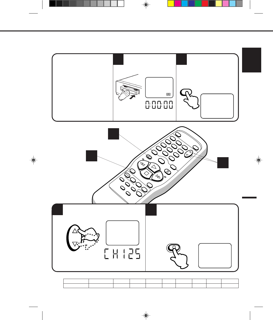
Turn on the TV and set to the video channel 3 or 4.
Press the TV/VCR selector button to select the VCR
mode.
Load a video cassette with the erase prevention tab
intact. The VCR will automatically turn on.
Check that the clock and date are correct (see page
25).
Press the SET + or – button to select the date,
then press the ENTER button.
•
•
•
•
CHECK BEFORE YOU BEGIN
32 Press the SET + or – button to select the
PROGRAM, then press the ENTER button.
1
When a TV is connected with an audio/video cable,
turn the TV and this VCR on and select the video
input mode on the TV.
SETTING THE TIMER RECORDING
1
2 3
MENU ENTER
ENTER
– SET + – SET + ENTER
1
4C83501A-E(P38-43) 27*10*99, 10:5540
41
ENGLISH
POWER EJECT
TV/VCR
COUNTER RESET
INPUT SELECT
REC/OTR
SLOW
SPEED
MENU
–+
–
+
SET
SKIP
SEARCH CLOCK/
COUNTER
–+
TRACKING
AUTO
CANCEL
ENTER
STOP
PLAY
F.FWD
REW
TIMER REC
PAUSE/STILL
CHANNEL
CALL
1
2
3
456
78
0
9
5
4
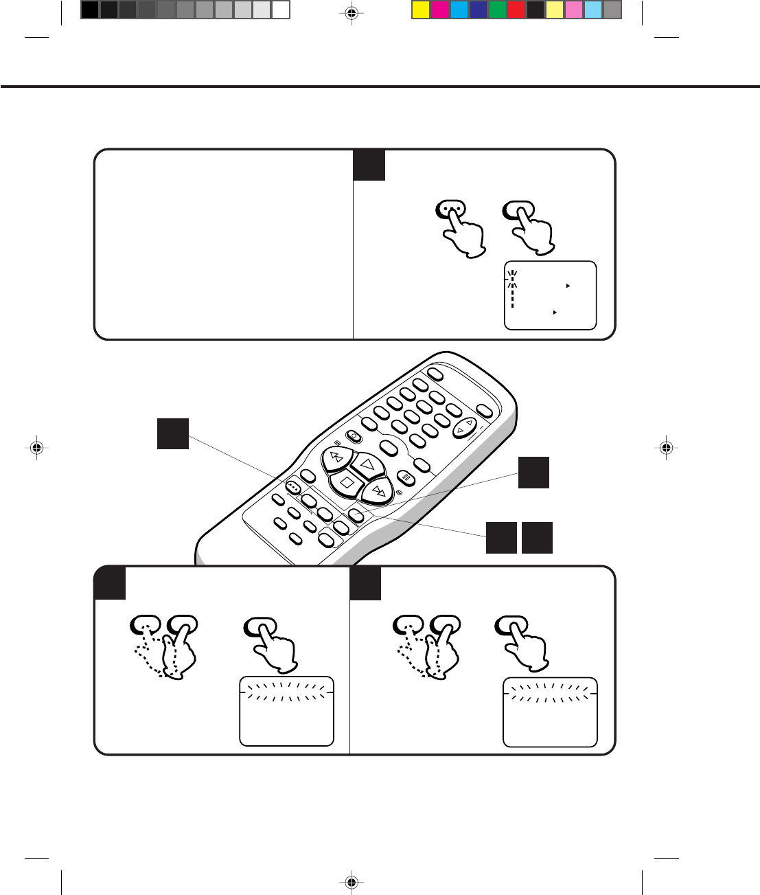
Set the start time, end time, channel and tape
speed as in step 3. To enter other programmes, repeat step 2
through 4. Or, press the MENU button twice to
return to the normal screen.
NOTE:
6
TO CORRECT THE SETTINGS
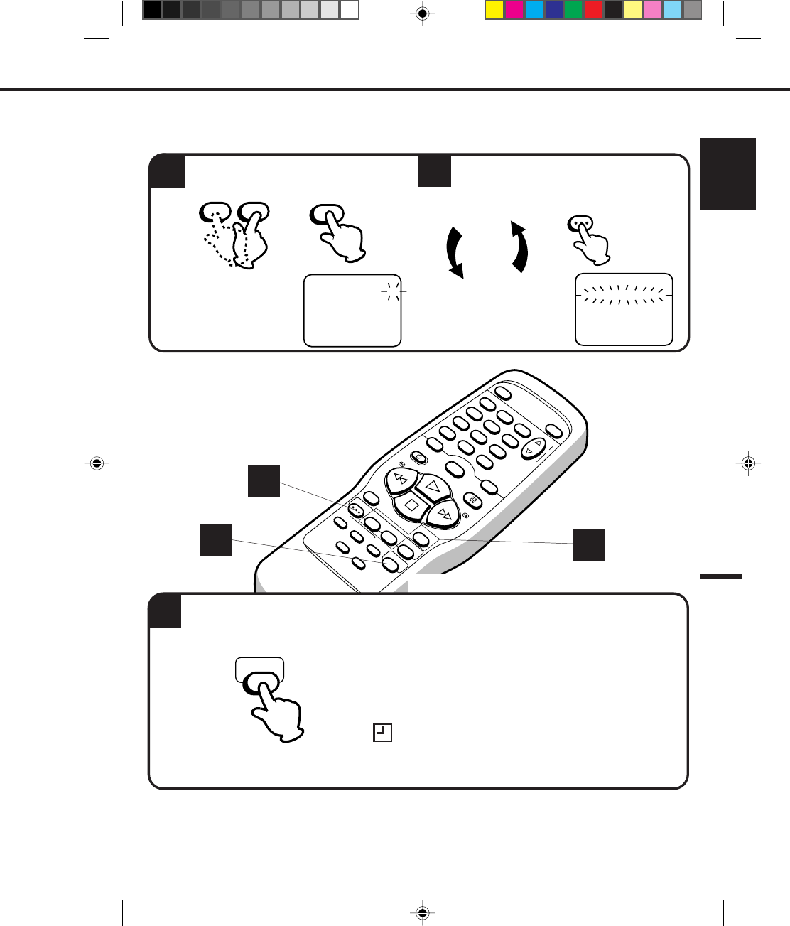
While setting, press the CANCEL button repeatedly until
the item to be corrected will flash then re-enter the
setting with the SET + or – button.
When finished, press the ENTER button.
To cancel timer recoreding, press TIMER REC button
again and the Timer Record indicator will go out.
Press the TIMER REC button. The power will
go off, the Timer Record indicator will light and
the VCR stands by for recording.
The VCR cannot be used while the Timer Record indicator is lit.
After a power failure or disconnection of the power plug, all programmed recording settings must be reset
upon resumption of power. In this case, reset the clock (see page 25) and reprogram any timer recordings.
To record from external source set the channel to "L". "L" will appear next to ch 125 (or 69).
•
•
•
4
– SET + ENTER
-:-- -:-- ---
-:-- -:-- ---
-:-- -:-- ---
-:-- -:-- ---
-:-- -:-- ---
-:-- -:-- ---
-:-- -:-- ---
------ -
------ -
------
26(SU)
11:00
PM
11:30
PM
125 SLP
-
------ -
------ -
------ -
------ -
〈
+/-/ENTER/CANCEL/MENU
〉
START
END
DATE CH
-:-- -:-- ---
-:-- -:-- ---
-:-- -:-- ---
-:-- -:-- ---
-:-- -:-- ---
-:-- -:-- ---
-:-- -:-- ---
------ -
------ -
------
26(SU)
11:00
PM
11:30
PM
125 SLP
-
------ -
------ -
------ -
------ -
〈
+/-/ENTER/CANCEL/MENU
〉
START
END
DATE CH
MENU
2
4
TIMER REC
5
6
4C83501A-E(P38-43) 27*10*99, 10:5641
42
POWER EJECT
TV/VCR
COUNTER RESET
INPUT SELECT
REC/OTR
SLOW
SPEED
MENU
–+
–
+
SET
SKIP
SEARCH CLOCK/
COUNTER
–+
TRACKING
AUTO
CANCEL
ENTER
STOP
PLAY
F.FWD
REW
TIMER REC
PAUSE/STILL
CHANNEL
CALL
1
2
3
456
78
0
9
The current day (Friday) SU-SA (Sunday to Saturday)
MO-SA (Monday to Saturday)
One month later
minus one day MO-FR (Monday to Friday)
WKL-WE WKL-TH (Weekly Thursday)
(Weekly Wednesday)
---
-:--
-:-- -:--
-:-- ---
-:-- -:-- ---
-:-- -:-- ---
-:-- -:-- ---
-:-- -:-- ---
-:-- -:-- ---
-:-- -:-- ---
------ -
------ -
------
------ -
-
------ -
------ -
------ -
------ -
〈
+/–/ENTER/CANCEL/MENU
〉
START
END
DATE CH
When setting the date in step 3, press the SET –
button repeatedly when the current day is displayed.
The setting changes as follows:
Example
Press the SET + or – button to select the TIMER REC
SET option in the MENU.
Then press the ENTER button to display the timer
program list.
Press the MENU button twice to return to the normal
screen.
TO CONFIRM THE SETTINGS
TO SET DAILY/WEEKLY TIMER
NOTE:
Press the SET + or – button to select the TIMER
REC SET option in the MENU.
Then press the SET + or – button to select the
unnecessary program, and press the CANCEL button
to cancel the program.
Do not overlap programs as portions of the
conflicting programs will be lost. The first
recording time has priority over the next
recording time as shown in the diagram.
NOTE:
IF THE PROGRAM OVERLAPS ANOTHER
TO CANCEL A PROGRAM
8 : 00 11 : 00
9 : 00 10 : 00
Program 1
Prog.1
Deleted Parts
Non Recorded Portion Parts
Prog.2 Prog.3
Program 2
Program 3
Recording
Control Settings
The everyday/every week recording can be made continuously until the recording is canceled or the tape
reaches the end.
During timer recording, the automatic rewinding mechanism does not function.
•
•
SETTING THE TIMER RECORDING (CONTINUED)
CANCEL
-:-- -:-- ---
-:-- -:-- ---
-:-- -:-- ---
-:-- -:-- ---
-:-- -:-- ---
-:-- -:-- ---
-:-- -:-- ---
------ -
------ -
------
26(SU)
11:00
PM
11:30
PM
125 SLP
-
------ -
------ -
------ -
------ -
〈+/-/ENTER/CANCEL/MENU〉
START
END
DATE CH
4C83501A-E(P38-43) 27*10*99, 10:5642
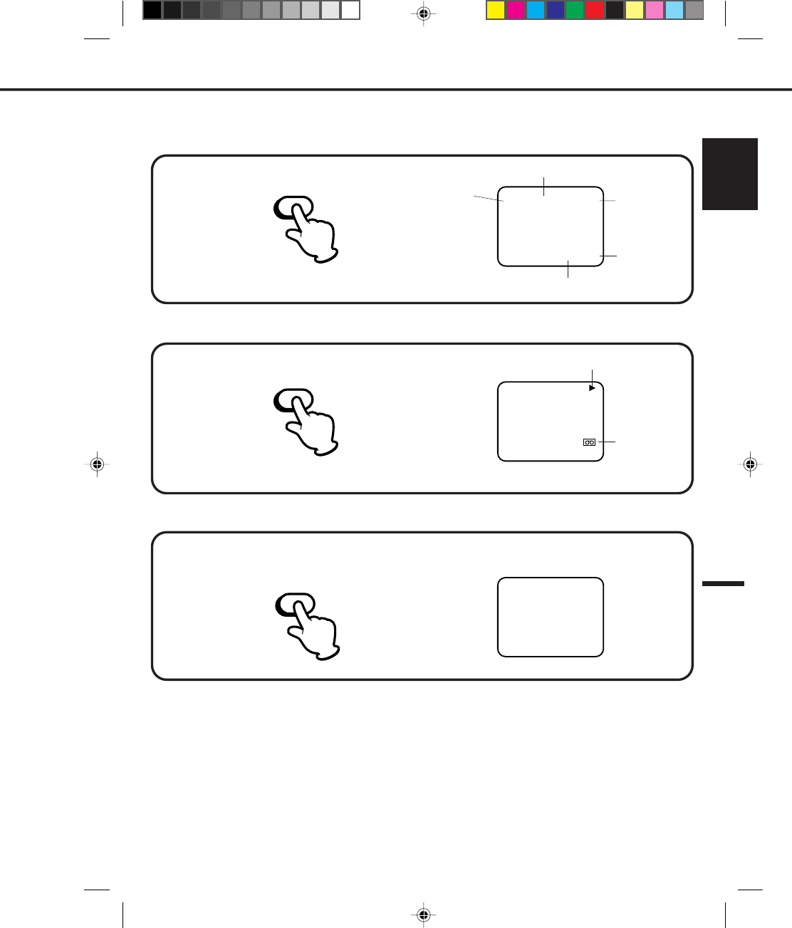
43
ENGLISH
Press the CALL button.
Press the CALL button.
Press the CALL button again to make the display disappear.
Press the CALL button again to make the display disappear.
Press the COUNTER RESET button. The counter will appear on the screen.
TO SET THE COUNTER TO '00:00:00'
WHILE OPERATING A TAPE
WHILE WATCHING TV
NOTE: If you rewind the tape from "00:00:00", a minus sign ("–") will be displayed in front of the time.
When you load a tape, the counter will change to "00:00:00".
The counter does not function on nonrecorded (blank) sections of the tape. When you rewind, fast forward
or play tapes through blank sections, the counter stops.
•
•
•
ON–SCREEN FUNCTION DISPLAY
00 : 00 : 00 SP
00 : 00 : 00 SP
CH 1258 : 30 AM THU
00 : 00 : 00 SP
CH 1258 : 30 AM THU
DAY OF THE WEEK
CHANNEL
TAPE SPEED
REAL TIME COUNTER
CLOCK
OPERATING MODE
TAPE IN
CALL
CALL
COUNTER RESET
4C83501A-E(P38-43) 27*10*99, 10:5643
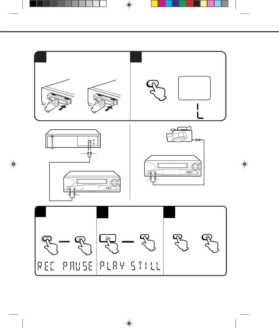
44
PLAYBACK CAMCORDER
TO AV JACK
1
It is recommended that you set the SPEED to the SP mode on the recording VCR for best results.
Unauthorized recording of copyrighted television programs, films, video tapes and other materials may
infringe on the rights of copyright owners and violate copyright laws.
NOTE:
Load a blank cassette tape with the erase
prevention tab intact into the recording VCR.
Load a previously recorded tape into the
playback VCR or CAMCORDER.
For duplicating a previously recorded tape from a
camcorder, follow the camcorder manufacturer’s
instructions. A typical camcorder dubbing hookup is
shown above.
35Press the PAUSE/STILL
button on both the VCRs
simultaneously to begin the
duplicating process.
4
Press the REC/OTR button
on the recording VCR, then
press the PAUSE/STILL
button.
•
•
2
▲
▲
PLAYBACK VCR
AUDIO/VIDEO cord (Not supplied) AUDIO/VIDEO cord
(Not supplied)
If you connect the VCR to another VCR or camcorder, you can duplicate a previously recorded tape. Make all
connections before turning on the power.
DUPLICATING A VIDEO TAPE
Press the INPUT SELECT button to select
AUDIO/VIDEO input position. The "LINE" will
appear on the screen. The "L" indicator will
light up on the display on the recording VCR.
PAUSE/
STILL
PLAY PAUSE/
STILL
Press the PLAY button on the
playback VCR, then press the
PAUSE/STILL button.
LINE
INPUT SELECT
TO VIDEO OUT TO AUDIO OUT
RECORDING VCR
TO VIDEO IN TO AUDIO IN
RECORDING VCR
TO VIDEO IN TO AUDIO IN
REC/OTR
PAUSE/STILL
PAUSE/STILL
4C83501A-E(P44-45) 27*10*99, 10:5544
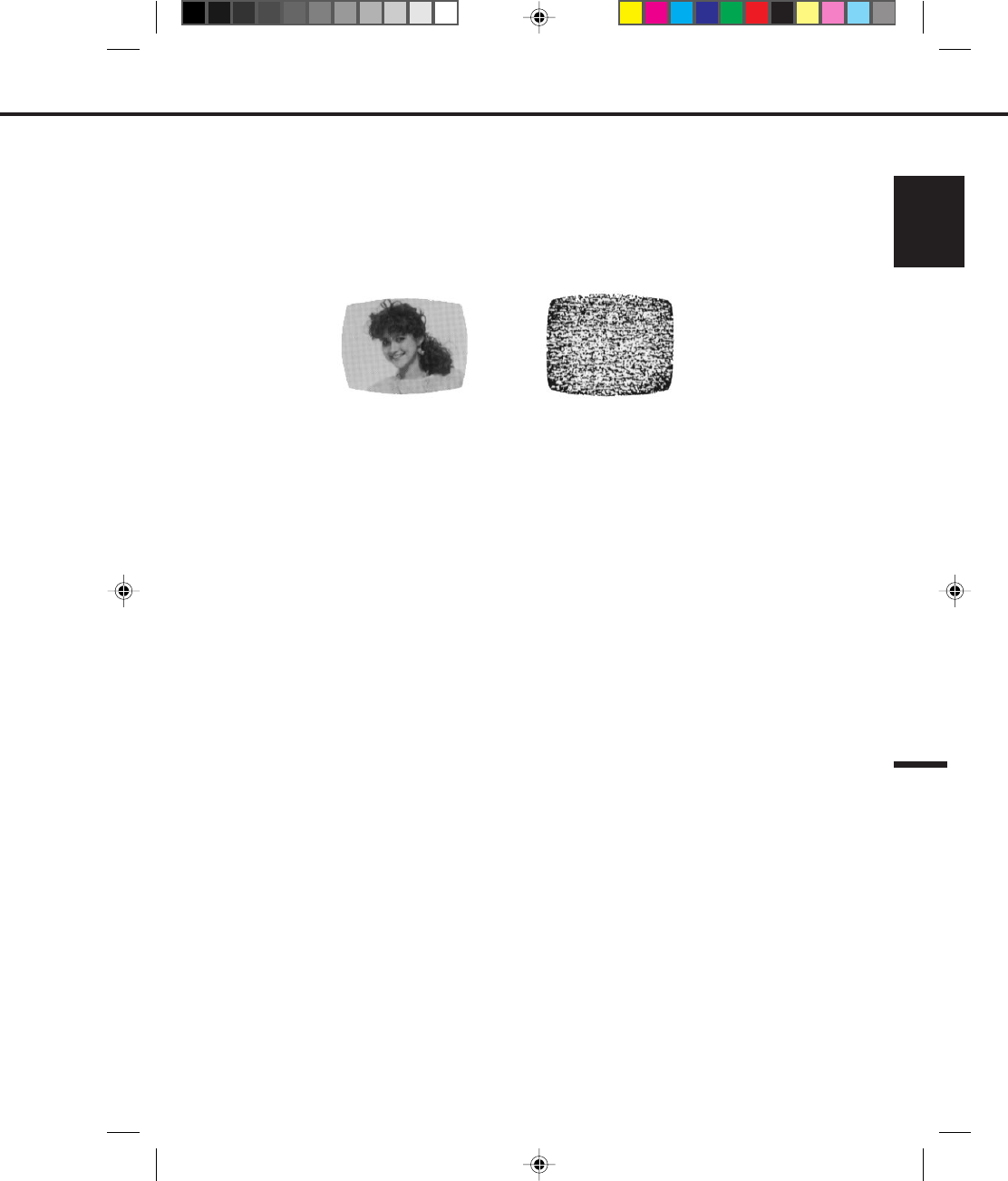
45
ENGLISH
The video heads are the means by which the VCR reads pictures from the tape during playback. In the unlikely
event that the heads become dirty enough to be clogged, no picture will be played back. This can easily be
determined if, during playback of a known good tape, there is good sound, but no picture (picture is extremely
snowy). If this is the case, have the video cassette recorder checked by qualified service personnel.
Video heads may eventually wear out and should be replaced when they fail to produce clear pictures.
To help prevent video head clogging, use only good quality VHS tapes. Discard worn out tapes.
VIDEO HEAD CLOGGING
AUTO HEAD CLEANING
VIDEO HEAD CLEANING
NOTE:
•
•
Snowy PictureGood Picture
The AUTO HEAD CLEANING system cleans the video heads automatically when a cassette is inserted or ejected to
prevent dirt from accumulating on the heads. However, manual head cleaning is needed if the picture on playback is
still unclear although the picture on program is normal. This failure signifies that the head is getting dirty and occurs
when playing poor quality or damaged tapes. If the heads require cleaning, use a high quality head cleaning system
or have them cleaned professionally.
DO NOT ATTEMPT TO CLEAN THE VIDEO HEADS OR SERVICE THE UNIT BY REMOVING THE TOP COVER.
4C83501A-E(P44-45) 27*10*99, 10:5545
46
The AC power cord is not con-
nected.
Cassette is not inserted.
Antenna connection is not correct.
Antenna cable is disconnected.
The video channel is not in the
correct position.
The TV is not set to the video
channel 3 or 4.
The TV/VCR selector is set at TV
mode. (The VCR indicator is not
on the display).
INPUT SELECT is set to the LINE
mode.
The TV/CATV menu option setting.
The erase prevention tab of the
video cassette is broken off.
INPUT SELECT is set to the LINE
mode.
The time is not set correctly.
The recording start/end time is
not set correctly.
The TIMER REC button has not
been pressed. (The TIMER REC
symbol is not lit on the display).
POWER
No power.
Although the power is on, it
does not operate.
TV BROADCAST RECEPTION
A TV program that is
selected by the VCR does
not appear on the screen.
A TV program selected by
the VCR does not appear in
color.
RECORDING
TV recording does not work.
Timer recording does not
work.
PAGEPOSSIBLE SOLUTIONSCAUSE
SYMPTOMS
BEFORE REQUESTING SERVICE
Make sure by first checking the following points.
23
26
38
41
41
30
9
Connect the AC power cord to the AC
outlet.
Insert a video cassette.
Reconnect the antenna cable. 14
14
Connect it correctly.
Set it to CH 3 or 4. 23
Set the TV channel selector to the 3
or 4 position.
Press the TV/VCR selector button.
(The VCR indicator is on the display). 23
Press the INPUT SELECT button to
select the TV mode. 44
Set the TV/CATV menu option to
select TV or CATV mode.
Place a piece of vinyl tape over the
gap.
Press the INPUT SELECT button to
select the TV mode. 44
Reset the present time. 25
Set the start/end time.
Press the TIMER REC button.
(The TIMER REC symbol is lit on
the display).
4C83501A-E(P46-54) 27*10*99, 10:4946
47
ENGLISH
PLAYBACK
No picture on screen when
playing back a recorded
tape.
Noise bars on screen.
REMOTE CONTROL
Remote control does not
work.
TV programs cannot be
seen using the TV selector.
The TV is not set to the video
channel 3 or 4.
Tracking adjustment beyond
range of automatic tracking
circuit.
Video heads are dirty.
The tape is worn or damaged.
It is not aimed at the remote
sensor.
Distance too far or too much light
in the room.
There is an obstacle in the path
of the beam.
The batteries are weak.
The +, – polarity of the bat-
teries are not inserted correctly.
The TV/VCR function is in the
VCR mode.
Set to the video channel 3 or 4 or
adjust the fine tuning button on
your TV set.
Adjust tracking manually using
the TRACKING + and – buttons on
remote control.
Have the video heads cleaned.
Try another tape.
Aim it at the remote sensor.
Operate within 15 feet (5 meters)
reduce the light in the room.
Clear the path of the beam.
Replace the batteries.
Insert correctly.
Set to TV, or turn off the VCR
power button.
POSSIBLE SOLUTIONS PAGE
CAUSE
SYMPTOMS
23
32
–
13
13
13
13
13
–
45
FOR ADDITIONAL SET-UP INFORMATION OR CUSTOMER SERVICE
PLEASE CALL:
1-800-919-3647
4C83501A-E(P46-54) 27*10*99, 10:4947

Video Head:
Power Source:
Power Consumption:
Tuner:
RF Channel Output:
Inputs/Outputs:
F.FWD/REW Time:
Speed Search:
Dimensions:
Weight:
Supplied accessories
4 Rotary Heads
120V, 60Hz
Approx. 11watts
181 Channel Freq. Synthesized
VHF
UHF
CATV
Channel 3 or 4, Switchable
Video:
Audio:
Antenna:
Approx. 1 min. 48 sec. (with T-120 Cassette Tape)
SP - 3 & 5 X Normal Speed
LP - 7 & 9 X Normal Speed
SLP - 9 & 15 X Normal Speed
14-3/16"W X 3-3/4"H X 9-7/16"D
8.8 Ibs
Remote Control (1)
75 ohm Coaxial Cable (1)
Tape Rewinder (1)
SPECIFICATIONS
48
Specifications are subject to change without notice.
2-13
14-69
14-36 (A)-(W)
37-59 (AA)-(WW)
60-85 (AAA)-(ZZZ)
86-94 (86)-(94)
95-99 (A-5)-(A-1)
100-125 (100)-(125)
01 (5A)
In (RCA) 1Vp-p 75 ohm
Out (RCA) 1Vp-p 75 ohm
In (RCA)–8dB/50K ohm
Out (RCA)–8dB/1K ohm
VHF/UHF IN 75 ohm coaxial
VHF/UHF OUT 75 ohm coaxial
4C83501A-E(P46-54) 27*10*99, 10:5048