ORing Networking IWM-7620 MT7620 WIFI Module User Manual Key words KM100
ORing Industrial Networking Corp. MT7620 WIFI Module Key words KM100
User Manual
MT7620 Module IWM-7620 Product Specification
Version:0.4
Date: 2015.8.13
Page 1 of 9
MT7620A Module IWM-7620
Product Specification
Version
Issue date
Changes
Remark
0.1
2014/3/06
Initial Version
0.2
2014/10/3
Modify memory configuration
0.3
2015/4/29
Update 2T2R data rate and temperature range
0.4
2015/8/13
Update output power
IMPORTANT
This document contains important Information and therefore
should not be disclosed to third parties without prior written consent of ORing Industrial Networking Co. Ltd.
Signature:
Author:
Reviewed by:
Approved by:
Remarks:
Isaac Chang
MT7620 Module IWM-7620 Product Specification
Version:0.4
Date: 2015.8.13
Page 2 of 9
1. Introduction
MT7620A IWM-7620 module is designed for easy-design-in low cost Wifi application。It has WAN,
LAN, UART, I2C, SPI, I2S, SDXC and GPIO interfaces. Support 2T2R operation.
2. Technical specification
Items
Specification
Supported Standard and Protocol
IEEE 802.11n, IEEE 802.11g, IEEE 802.11b, IEEE 802.3, IEEE
802.3u, CSMA/CA, CSMA/CD,TCP/IP,DHCP, ICMP, NAT, PPPoE
Dimension
35*30 mm
Power consumption
< 350mA
Operating Temperature Range
-30 ~ 70 deg. C
Storage Temperature Range
-40 ~ 85 deg. C
WAN Port
one 10/100M adaptive RJ45 port
LAN Port
one 10/100M adaptive RJ45 port
RF Parameters
Frequency
Range
2.4~2.4835GHz
Baud Rate
1T1R :
MCS
Data rate (Mbit/s)
index
20 MHz channel
40 MHz channel
800 ns
400 ns
800 ns
400 ns
0
6.5
7.2
13.5
15
1
13
14.4
27
30
2
19.5
21.7
40.5
45
3
26
28.9
54
60
4
39
43.3
81
90
5
52
57.8
108
120
6
58.5
65
121.5
135
7
65
72.2
135
150
2T2R
MCS
Data rate (Mbit/s)
MT7620 Module IWM-7620 Product Specification
Version:0.4
Date: 2015.8.13
Page 3 of 9
index
20 MHz channel
40 MHz channel
800 ns
400 ns
800 ns
400 ns
8
13.00
14.40
27.00
30.00
9
26.00
28.90
54.00
60.00
10
39.00
43.30
81.00
90.00
11
52.00
57.80
108.00
120.00
12
78.00
86.70
162.00
180.00
13
104.00
115.60
216.00
240.00
14
117.00
130.00
243.00
270.00
15
130.00
144.40
270.00
300.00
IEEE 802.11g:54/48/36/24/18/12/9/6(adaptive )
IEEE 802.11b:11/5.5/2/1M(adaptive )
Number of
Channel
13
Modulation
Scheme
DBPSK、DQPSK、CCK and OFDM(BPSK/QPSK/16-QAM/64-QAM)
Sensitivity @
PER
150M:-68dBm@10% PER;130M:-68dBm@10% PER;
108M: -68dBm@10% PER;54M:-72dBm@10% PER
11M:-85dBm@8% PER;6M:-88dBm@10% PER
1M:-90dBm@8% PER;
Output Power
802.11b: 19 dBm ± 1.5dBm@11Mbps (2T2R total power)
802.11g: 17.5 dBm ± 1.5dBm@54Mbps (2T2R total power)
802.11gn HT20: 16.5 dBm ± 1.5dBm @MCS7 (2T2R total power)
802.11gn HT40: 14.5 dBm ± 1.5dBm @MCS7 (2T2R total power)
Antenna
Two IPEX I connectors for two external antenna( 2T2R)
WIFI Operation Mode
Client/AP
System Service
Virtual Server:Internal web server for browser to access
Device Management
Area setting
Restore to default factory setting
Software upgrade
Reboot

MT7620 Module IWM-7620 Product Specification
Version:0.4
Date: 2015.8.13
Page 4 of 9
Change password
WLAN Security Mode
OPENWEP
SHAREDWEP
WEPAUTO
WPA
WPA-PSK
WPA2
WPA2-PSK
WPAPSKWPA2PSK
WPA1WPA2(WPA and WPA2 hybrid mode)
802.1x
3. Software features
Support WPS
Support AP(Access point)、Client(Wifi Station) mode
AP mode
o Default operation mode. In this mode, the module work as an Access Point, don't need any
configuration.
o User can use PC via RJ45 or smart phone via Wifi to login MT7620A AP mode and change
the default configuration ( through browser).
Client mode
o In this mode, module is a Wifi station.
4. Development tool :
We provide development tool for easy connection of power, RS-232, LAN, WAN, and USB port.
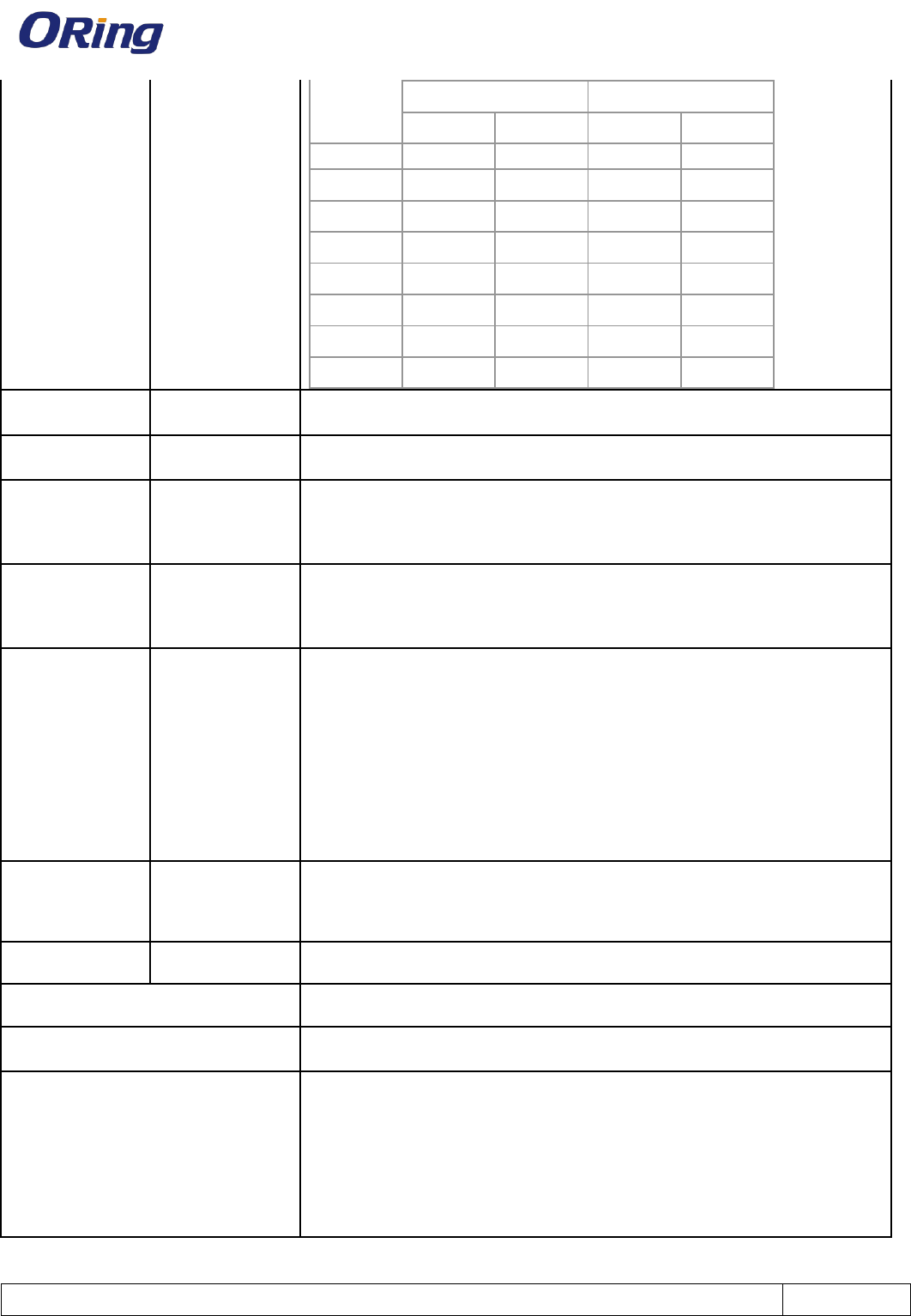
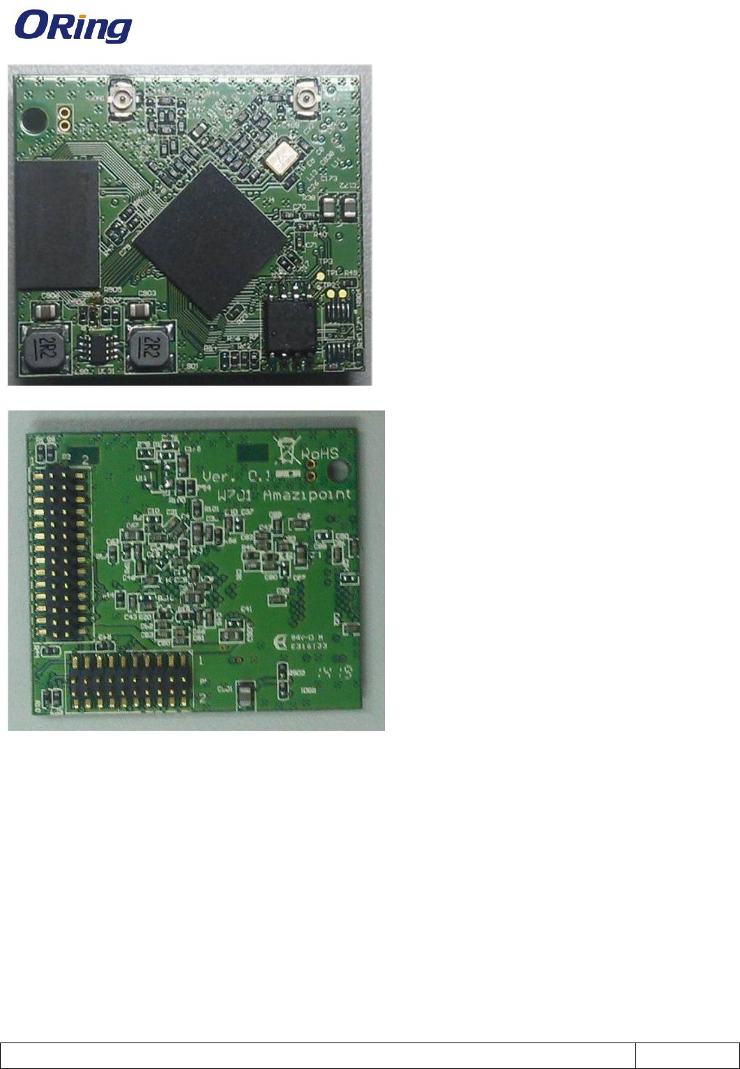
5. Module Dimension : 35*30 mm
MT7620 Module IWM-7620 Product Specification
Version:0.4
Date: 2015.8.13
Page 5 of 9
There are two 1.27mm pitch header on the bottom side of module P1 and P2.
6. Pin Assignment
P1 :
MT7620 Module IWM-7620 Product Specification
Version:0.4
Date: 2015.8.13
Page 6 of 9
Multi 1 Multi 2 GPIO Main Main GPIO Multi 2 Multi 1
GPIO50 SD_CDT 1 2 SD_CMD GPIO51
GPIO52 SD_D0 3 4 SD_D3 GPIO55
GPIO53 SD_D1 5 6 SD_D2 GPIO54
GPIO48 SD_WP 7 8 SD_CLK GPIO49
REFCLK
WDT_RST
910 POR
GPIO40 LINK0 11 12 GPIO0
GPIO41 LINK1 13 14 SPI_MISO GPIO6
REFCLK GPIO37 SPI_CS1 15 16 UART_TX GPIO15
GPIO4 SPI_CLK 17 18 UART_RX GPIO16
GPIO42 LINK2 19 20 SPI_MOSI GPIO5
P2 :
Multi 1 Multi 2 GPIO Main Main GPIO Multi 2 Multi 1
GPIO2 I2C_SCLK 1 2 I2C_SD GPIO1
TXO3_P 3 4 RXI4_P
TXO3_N 5 6 RXI4_N
RXD PCMDTX GPIO14 RIN 7 8 LINK4 GPIO44
RTS_N PCMFS GPIO11 DTR_N 910 GND
I2SSDI GPIO10 RXD 11 12 USB_P
I2SCLK GPIO7 RTS_N 13 14 USB_N
3.3VD 15 16 GND
3.3VD 17 18 TXO4_P
TXD PCMCLK GPIO12 DCD_N 19 20 TXO4_N
I2SWS GPIO8 TXD 21 22 RXI3_N
CTS_N PCMDRX GPIO13 DSR_N 23 24 RXI3_P
GPIO43 LINK3 25 26 CTS_N GPIO9 I2SSDO
GPO72 WLAN_LED 27 28 1.8VD
P1 :
Pin #
Function
Direction
Description
1
SD_CDT
In
SDXC Card Detect
2
SD_CMD
Out
SDXC Command
MT7620 Module IWM-7620 Product Specification
Version:0.4
Date: 2015.8.13
Page 7 of 9
3
SD_D0
In/Out
SDXC Data0
4
SD_D3
In/Out
SDXC Data3
5
SD_D1
In/Out
SDXC Data1
6
SD_D2
In/Out
SDXC Data2
7
SD_WP
In
SDXC Write Protect
8
SD_CLK
Out
SDXC Clock
9
WDT_RST
Out
Watchdog timeout reset, can be configured as ref clock output
10
POR
In
Power on reset input, low active
11
LINK0
Out
Link LED for port 0
12
GPIO0
Out
GPIO0 or WPS push button
13
LINK1
In/Out
Link LED for port 1
14
SPI_MISO
In
SPI MISO signal
15
SPI_CS1
Out
SPI chip select signal 1
16
UART_TX
A
Console UART TXD signal
17
SPI_CLK
Out
SPI clock output
18
UART_RX
A
Console UART RXD signal
19
LINK2
Out
Link LED for port 2
20
SPI_MOSI
Out
SPI MOSI signal
P2 :
Pin #
Function
Direction
Description
1
I2C_SCLK
In/Out
I2C Clock signal
2
I2C_SD
In/Out
I2C Data signal
3
TXO3_P
A
Tx positive for port 3
4
RXI4_P
A
Rx positive for port 4
5
TXO3_N
A
Tx negative for port 3
6
RXI4_N
A
Rx negative for port 4
7
RIN
Full UART RIN signal
8
LINK4
Out
Link LED for port 4
9
DTR_N
Full UART DTR signal
10
GND
Power ground
11
RXD
Full UART RXD signal
12
USB_P
In/Out
USB signal poistive
13
RTS_N
Full UART RTS_N signal
14
USB_N
In/Out
USB signal negative

MT7620 Module IWM-7620 Product Specification
Version:0.4
Date: 2015.8.13
Page 8 of 9
15
3.3VD
Power In
3.3V input
16
GND
Power ground
17
3.3VD
Power In
3.3V input
18
TXO4_P
A
Tx positive for port 4
19
DCD_N
Full UART DCD_N signal
20
TXO4_N
A
Tx negative for port 4
21
TXD
Out
Full UART TXD
22
RXI3_N
A
Rx negative for port 3
23
DSR_N
In/Out
Full UART DSR_N signal
24
RXI3_P
A
Rx positive for port 3
25
LINK3
Out
Link LED for port 3
26
CTS_N
Full UART CTS_N signal
27
WLAN_LED
Out
WLAN LED output, active low
28
1.8VD
Power input
1.8V input
7. Memory configuration
Depending on customer's request, the module can be shipped with following configuration :
Flash size : 2MB, 4MB, 8MB, 16MB, 32MB, 64MB
DDR2 size : 64MB, 128MB
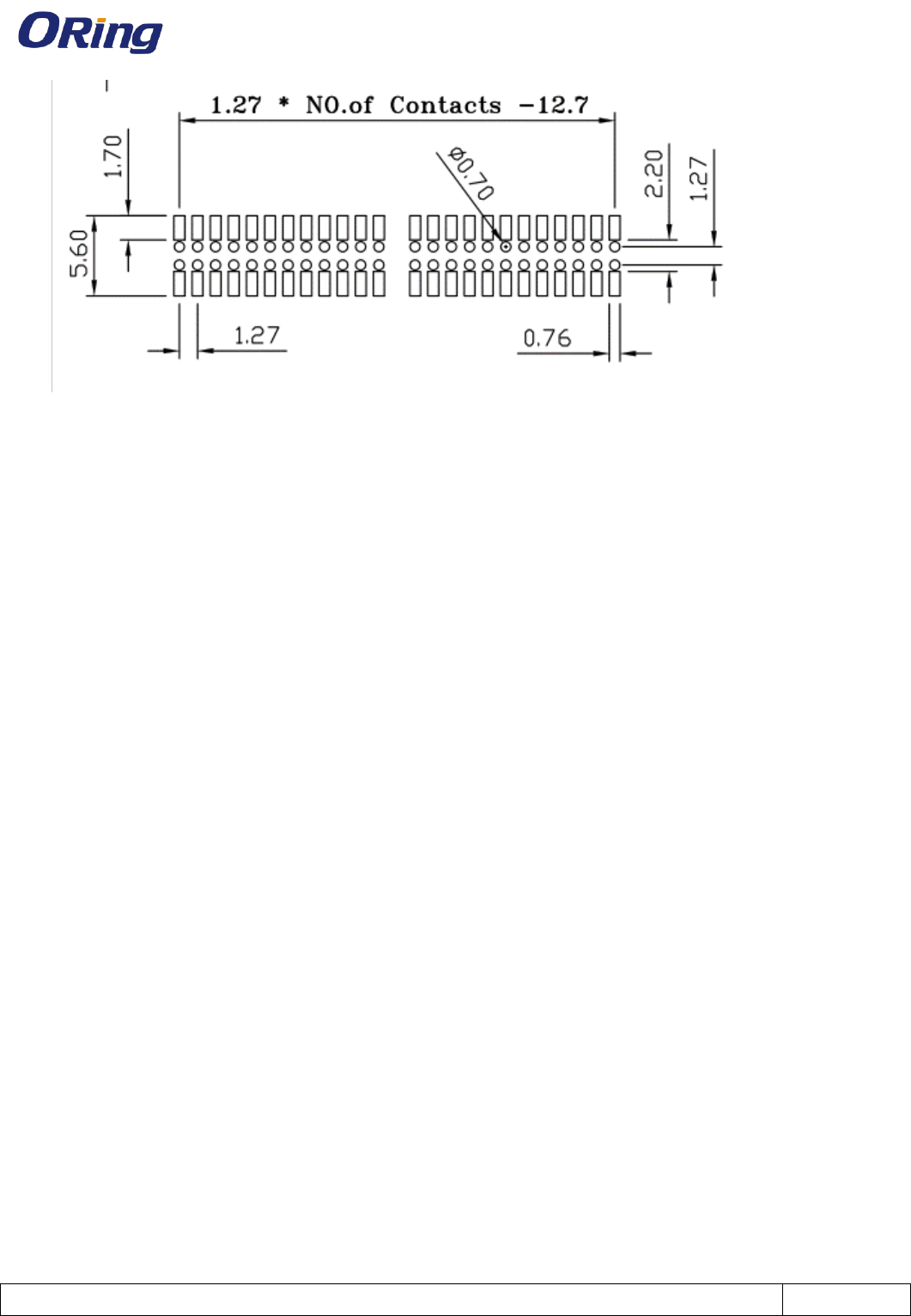
8. Mechanical Application Notes
1. CON0 and CON1 are IPEX1 connectors on top side
2. P1 is 2*10 pins 1.27mm male header on bottom side for signals
3. P2 is 2*14 pins 1.27mm male header on bottom side for signals
4. Footprint of P1, P2 is as following, the coordinate of pin1 footprint center for P1 and P2 are
(29.5, 10.975) and (9.575,1.425), Please note that this coordinate is the center of pad, not
center of header pin.
MT7620 Module IWM-7620 Product Specification
Version:0.4
Date: 2015.8.13
Page 9 of 9
5. H1, H2, H3, H4 are slot holes used for install metal shielding cover if needed
6. D1 is diameter 2.1mm hole for screw fixing
7. D2 is diameter 2.1mm half hole for screw fixing
8. P3 is a 2 pins dip type header holes with 1.27mm pitch. Since P1 and P2 are all located on
lower side, this socket can be used optionally to mount module on base PCB for balancing
the force of upper side.
9. The mechanical drawing in .dxf format is available under request.
9.Compliance
FCC Statement
This device complies with Part 15 of the FCC Rules. Operation is subject to the following two conditions:
(1) this device may not cause harmful interference and(2) this device must accept any interference received, including
interference that may cause undesired operation.