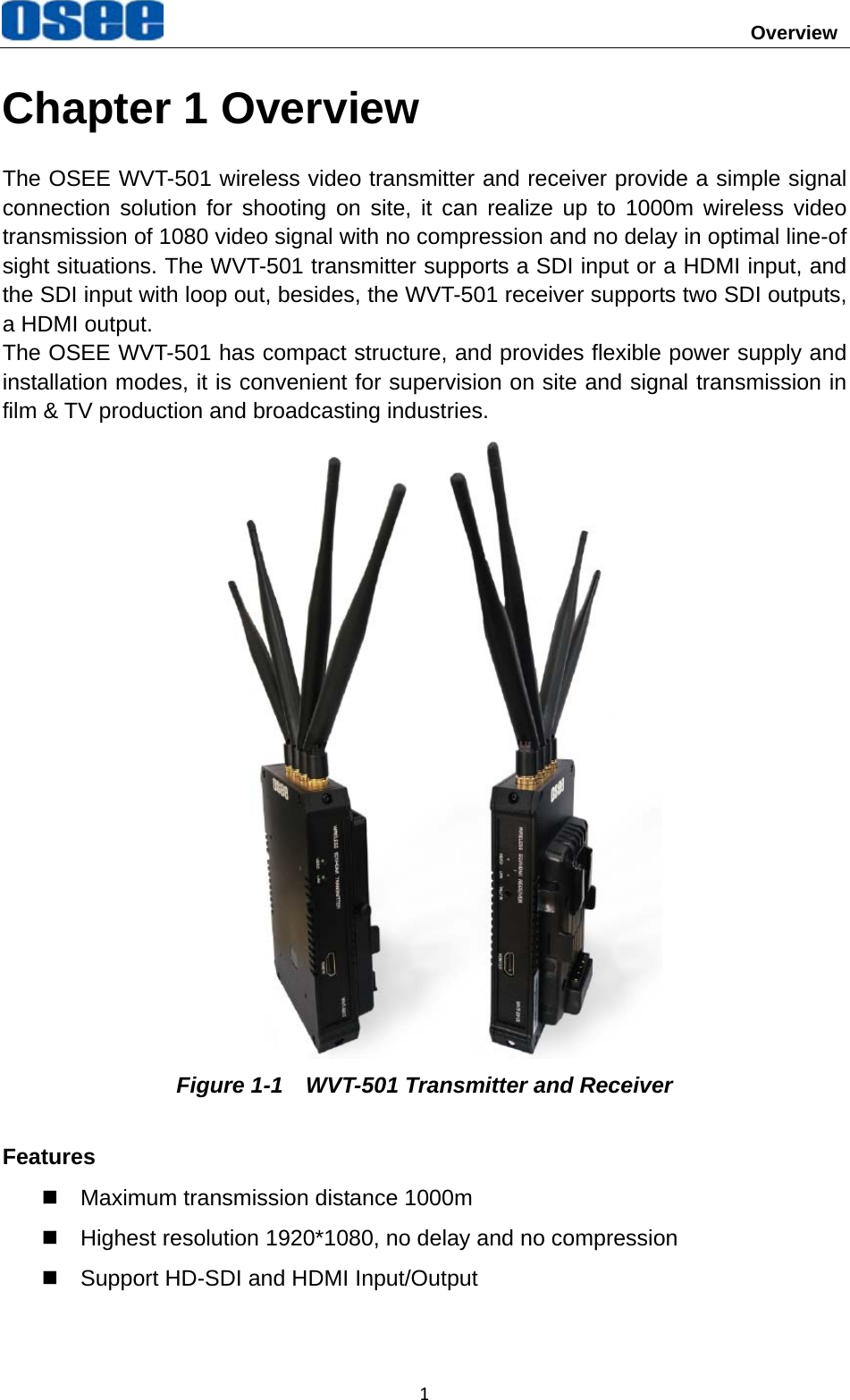
OSEE TECHNOLOGY WVT-501 Wireless Video Transmitter User Manual

OSEE TECHNOLOGY CO.,LTD. Wireless Video Transmitter Users Manual

User manual

           WVT-501 Wireless Video Transmitter and Receiver        User Manual
     Product Information Model:  WVT-501 Version:  V010000 Release Date:  September 26th, 2017     Company OSEE TECHNOLOGY CO., LTD.     Contact Information OSEE TECHNOLOGY CO., LTD. Post Code:  100094 Tel:  (+86) 010-62434168 Fax:  (+86) 010-62434169 Web:  http://www.osee-dig.com.cn/
About this manual ImportantThe following symbols are used in this manual: y  The further information or know-how for described subjects above which helps user to understand them better. y  The safety matters or operations that user must pay attention to when using this product. y  Any Changes or modifications not expressly approved by the party responsible for compliance could void the user’s authority to operate the equipment. This device complies with part 15 of the FCC Rules. Operation is subject to the following two conditions: (1) This device may not cause harmful interference, and (2) this device must accept any interference received, including interference that may cause undesired operation. FCC Radiation Exposure Statement:This equipment complies with FCC radiation exposure limits set forth for an uncontrolled environment .This transmitter must not be co‐located or operating in conjunction with any other antenna or transmitter.This equipment should be installed and operated with minimum distance 20cm between the radiator &you body.
Note: This equipment has been tested and found to comply with the limits device, pursuant to part 15 of the FCC Rules. limits are designed to provide reasonable  protection against harmfulsidential installation. This equipment generates can radiate radio frequency energy and, if not installed and used in accordancethe instructions, may cause harmful interference to radio communications. that interference will not occur in a particularcause harmful interference to radio or televisionreception, which can be determined by turning the equipment off and on, the user  try to correct the interference by one or  more of the following —Reorient or relocate the receiving antenna.      —Increase the separation between the equipment and receiver.      —Connect the equipment into an outlet on a circuit different from that to which connected.    —Consult the dealer or an experienced radio/TV technician for help.     ContentsThe user manual applies to the following device types: y WVT-501 The images and descriptions of WVT-501 are adopted as examples in the following document. Before reading the manual, please confirm the device type. for a Class B digital  These interference in a re uses andwith However, there is no guaranteeis encouraged tomeasures:   the receiver is installation. If this equipment does
                                       Overview 1Chapter 1 Overview The OSEE WVT-501 wireless video transmitter and receiver provide a simple signal connection solution for shooting on site, it can realize up to 1000m wireless video transmission of 1080 video signal with no compression and no delay in optimal line-of sight situations. The WVT-501 transmitter supports a SDI input or a HDMI input, and the SDI input with loop out, besides, the WVT-501 receiver supports two SDI outputs, a HDMI output. The OSEE WVT-501 has compact structure, and provides flexible power supply and installation modes, it is convenient for supervision on site and signal transmission in film & TV production and broadcasting industries.  Figure 1-1    WVT-501 Transmitter and Receiver Features   Maximum transmission distance 1000m   Highest resolution 1920*1080, no delay and no compression   Support HD-SDI and HDMI Input/Output
Overview  2  User configurable frequency bands   Support SDI/HDMI interleaving output   With internal battery to achieve power switch for uninterrupted work   Provide battery plate as standard configuration   CNC aluminum, laser lithography, ruggedized  Support TALLY input/output
Safety  3Warnings: Read, keep and follow all of these instructions for your safety. Heed all warnings.  Device y  Install in accordance with the manufacturer's instructions. y  Do not beat with a hard object or scratch the unit. y  Refer all servicing to qualified service personnel. Servicing is required if any of the following occurs:   The unit has been exposed to rain or moisture.   Liquid had been spilled or objects have fallen onto the unit.   The unit has been damaged in any way, such as when the power-supply cord or plug is damaged.     The unit does not operate normally, or has been dropped. y  Clean only with dry cloth. y  Do not block any ventilation openings. Leave enough space around the unit for ventilation. y  Do not use this unit near water. y  A nameplate indicating operating voltage, etc., is located on the rear panel. y  The socket-outlet shall be installed near the equipment and shall be easily accessible. y  To reduce the risk of fire or electric shock, do not expose the unit to rain or moisture. y  To avoid electrical shock, do not open the cabinet. Refer all servicing to qualified service personnel.   y  If the product needs replacement parts, make sure that the service person use replacement parts specified by the manufacture, or those with the same characteristics and performance as the original parts. Use of unauthorized parts can result in fire, electric shock and/or other damage. y  The panel used in this produce is made of glass. Therefore, it can break when it is dropped or applied with impact. Be careful not to be injured by broken glass pieces. y  Specifications are subject to change without notice.
                          Unpack and Installation 4Chapter 2 Unpack and Installation Unpack: When unpacking the WVT-501, pleased verify that none of the components listed in Table 3.1 are damaged or missing. If there are any components missing, please contact your distributors or OSEE for it. Table 2-1    Packing List2No.  Item  Quantity 1  WVT-501 Transmitter(with battery plate)  1 2  WVT-501 Receiver(with battery plate)  1 3  Antenna  8 4 User Manual  1 5  Warranty Card  1 Installation: 1. Prepare for installation Please follow the procedures below before installing WVT-501: y  Check the package and equipment for any visible damage that may have occurred during transit. y  Confirm all the items listed on the packing list have been received. y  Remove all the packing material including electrostatic-resistant packing. y  Retain these packing materials for future use. 2. Connect the antennas to the top side of the unit, each needs four antennas, as shown in Figure3-1. Put the antennas as fan arrangement to transmit or receive signals more steadily. 3. Connect required signal cables to the corresponding interfaces.  Figure 2-1  Antenna Interfaces 4. Connect the 7~17VDC power source to DC IN interface.
Unpack and Installation  55. As the final step, power on the device.  Battery Powered WVT-501 provides not only DC powered supply mode, but also battery powered supply mode. WVT-501 provides one battery slot to connect to the battery plug on the battery plate, as shown in Figure2-2. Then connect a battery to the battery plate, thus power on the unit by battery.  Figure 2-2  Battery Plate  y  Please use the power adapter supplied to avoid unnecessary trouble. y  Make sure the power cord grounding well.
 Locations and Function of Parts and Control 6Chapter 3 Locations and Function of Parts and Control 3.1 Parts and Functions The parts of WVT-501 is shown as below, there are various input and output interfaces:  WVT-501 Transmitter  Figure 3.1-1    Left View of WVT-501 Transmitter  Figure 3.1-2    Right View of WVT-501 Transmitter  WVT-501Receiver  Figure 3.1-3    Left View of WVT-501 Receiver
Locations and Function of Parts and Control   7 Figure 3.1-4    Right View of WVT-501 Receiver  WVT-501 Transmitter  WVT-501 Receiver Interface SDI IN(BNC)  SDI1 OUT(BNC) SDI OUT(BNC, loop out)  SDI2 OUT(BNC) HDMI IN(Type A)  HDMI OUT(Type A) Antenna (PR-SMA Male)  Antenna(PR-SMA Male) DC IN(2pins LEMO)  DC IN(2pins LEMO) TALLY OUT(3.5mm)  TALLY IN (3.5mm) 1. Power Input Plug the power supply to this interface to provide power to the device. The DC input voltage range is 7~17VDC. 2. Power Switch Press this part to switch on or switch off the power. Push the button to the “ON” side to switch on the power, and the OLED screen is lit up. Push the button to the “OFF” side to switch off the power, and the OLED screen is lit off.   y  It lasts about one minute for starting operation, and please don’t do any operations during starting the device. y  There are four antenna interfaces at the top of WVT-501 unit, and five 1/4” inch thread interfaces at the bottom.
                    Locations and Function of Parts and Control 83.2 OLED Screen and Buttons It provides an OLED screen and some buttons, the details are as below:  Figure 3.2-1    OLED Screen and Buttons 3.2.1 OLED Screen As shown in Figure 3.2-1, there is an OLED screen at the top right side of the unit, and it will display the signal strength, frequency point and video format.  Items  Description Signal Strength It displays the signal strength. Frequency Point It displays the frequency point. VIDEO It displays the video format if there is a video input, otherwise, it displays nothing at this position. 3.2.2 Frequency Point and Parity Buttons  Operation CH Short press for 3 seconds Press  this  button  to  switchfrequency point PAR Long press for 6 seconds Press this button to achieve WPSparity 5190
Locations and Function of Parts and Control   93.2.3 Indicator Status There are a VIDEO indicator and a LINK indicator at the bottom of WVT-501. The different combinations of these two indicators and the different status of the unit are as the table below: Operation  Indicator Status Description Switch Channel    VIDEO and LINK flash quickly  and  alternately(Green) Parity  VIDEO and LINK flash quickly at the same time(Green) Communication normally, but no video LINK constant light(Green), VIDEO flash(Green) Both communication and video displays normally VIDEO constant light (Green), LINK constant light(Green) 3.2.4 Start Up Press the power button at the side of the unit, the position of the power button is as shown in Figure 3.2-2:  Figure 3.2-2    The Position of Power On Switch Push the button to the “ON” side to switch on the power, and the OLED screen is lit up. Push the button to the “OFF” side to switch off the power, and the OLED screen is lit off.
                    Locations and Function of Parts and Control 103.3 Supported Signal Format Supports the following signal format for this device is as shown in Table 3.3-1: Table 3.3-1  Supported Signal Format  SDI  HDMI 480P60   { 576P50   { 720P50  { { 720P60  { { 1080I50  { { 1080I60  { { 1080p24  { { 1080P25   { 1080P30  { { 1080P50  { { 1080P60  { {
Specifications 11Chapter 4 Specifications 4.1 Production Details Specification  Values Model  Wireless Video Transmitter Wireless Video Receiver Interface SDI IN(BNC)  SDI1 OUT(BNC) SDI LOOP OUT(BNC)  SDI2 OUT(BNC) HDMI IN(Type A)  HDMI OUT(Type A) Antenna(PR-SMA male)  Antenna(PR-SMA male) DC IN(2pins LEMO)  DC IN(2pins LEMO) TALLY OUT(3.5mm)  TALLY IN (3.5mm) Indicators  LINK-Green; VIDEO-Green; TALLY-Red LINK-Green; VIDEO-Green Network Standard  802.11n  / Receiver Sensitivity  /  -70dBm Working Frequency  5190MHz,  5230 MHz,  , 5755 MHz 5795 MHz Transmit Power  17dBm Status Display  OLED screen, displaying signal strength and current frequency Modulation Mode  OFDM Occupied Bandwidth  40MHz Video Format  HDMI: 576P, 480P, 720p 50/60, 1080i 50/60, 1080p24/25/30/50/60 SDI: 720p 50/60,1080i 50/60,1080p24/30/50/60 Internal Battery Charging Current  500mA 8.4V External Voltage Range  7-17V DC Power Consumption <9W
Specifications   12Specification  Values Physical Characters Operating Temperature  0~40°C Dimension (L x W x H)  168x107.1x27mm(without antennas) Weight  540g *The unit about the appearance attributes in above table is mm. 4.2 Dimensions The description of the WVT-501 dimensions are as shown in the following figures (Unit: mm):  Wireless Video Transmitter Without Battery Plate  With Battery Plate    Figure 4.2-1  Front View(Unit: mm)
 Specifications 13 Figure 4.2-2  Back View(Unit: mm)                        Figure 4.2-3    Side View(Unit: mm)
Specifications   14 Figure 4.2-4    Top View (Unit: mm)  Wireless Video Receiver Without Battery Plate  With Battery Plate    Figure 4.2-5  Front View(Unit: mm)
 Specifications 15 Figure 4.2-6  Back View(Unit: mm)                        Figure 4.2-7    Side View(Unit: mm)
Specifications   16 Figure 4.2-8    Top View (Unit: mm)  y  Specifications are subject to change without notice.     ------------------No Text Below------------------
FOR MORE INFORMATION PLEASE VISIT: http://www.osee-dig.com.cn/ OSEE TECHNOLOGY CO., LTD. Tel:  (+86) 010-62434168 Fax:  (+86) 010-62434169

Navigation menu