OTC Engineering S L 210M1100 Motorcycle dahsboard with Bluetooth for communications with mobile phone User Manual
OTC Engineering S.L. Motorcycle dahsboard with Bluetooth for communications with mobile phone Users Manual
Users Manual
OWNER'S MANUAL 2017
125 Duke
Art. no. 3213561en

DEAR KTM CUSTOMER 1
*3213561en*
3213561en
02/2017
DEAR KTM CUSTOMER
Congratulations on your decision to purchase a KTM motorcycle. You are now the owner of a state-of-the-art sports motorcycle that will
give you enormous pleasure if you service and maintain it properly.
We hope you enjoy your new vehicle!
Enter the serial numbers of your vehicle below.
Chassis number ( p. 20) Dealer's stamp
Engine number ( p. 21)
Key number ( p. 21)
The Owner's Manual contained the latest information for this model series at the time of going to print. However, minor differences due to
further developments in design cannot be ruled out completely.
All specifications are non-binding. KTM Sportmotorcycle GmbH specifically reserves the right to modify or delete technical specifications,
prices, colors, forms, materials, services, designs, equipment, etc., without prior notice and without specifying reasons, to adapt these to
local conditions, as well as to stop production of a particular model without prior notice. KTM accepts no liability for delivery options, devi-
ations from illustrations and descriptions, misprints, and other errors. The models portrayed partly contain special equipment that does not
belong to the regular scope of supply.
© 2017 KTM Sportmotorcycle GmbH, Mattighofen Austria
All rights reserved

DEAR KTM CUSTOMER 2
Reproduction, even in part, as well as copying of all kinds, is permitted only with the express written permission of the copyright owner.
ISO 9001(12 100 6061)
According to the international quality management standard ISO 9001, KTM uses quality assurance processes that lead to
the maximum possible quality of the products.
Issued by: TÜV Management Service
KTM Sportmotorcycle GmbH
5230 Mattighofen, Austria
This document is valid for the following models:
125 Duke EU (F4003Q1, F4003Q2, F4003Q3, F4003Q4)
TABLE OF CONTENTS 3
TABLE OF CONTENTS
1 MEANS OF REPRESENTATION ........................................ 7
1.1 Symbols used ...................................................... 7
1.2 Formats used....................................................... 8
2 SAFETY ADVICE.............................................................. 9
2.1 Use definition...................................................... 9
2.2 Misuse................................................................ 9
2.3 Safety advice....................................................... 9
2.4 Degrees of risk and symbols ................................ 10
2.5 Tampering warning............................................. 10
2.6 Safe operation ................................................... 11
2.7 Protective clothing ............................................. 12
2.8 Work rules......................................................... 12
2.9 Environment...................................................... 12
2.10 Owner's Manual ................................................. 13
3 IMPORTANT NOTES...................................................... 14
3.1 Manufacturer and implied warranty...................... 14
3.2 Operating and auxiliary substances ...................... 14
3.3 Spare parts, accessories ..................................... 14
3.4 Service ............................................................. 15
3.5 Figures ............................................................. 15
3.6 Customer service................................................ 15
4 VIEW OF VEHICLE ........................................................ 16
4.1 View of vehicle, front left (example) ..................... 16
4.2 View of vehicle, rear right (example) .................... 18
5 SERIAL NUMBERS ....................................................... 20
5.1 Chassis number ................................................. 20
5.2 Type label ......................................................... 20
5.3 Engine number .................................................. 21
5.4 Key number....................................................... 21
6 CONTROLS................................................................... 22
6.1 Clutch lever....................................................... 22
6.2 Hand brake lever................................................ 22
6.3 Throttle grip ...................................................... 23
6.4 Switches on the left side of the handlebar ............ 23
6.4.1 Combination switch........................................ 23
6.4.2 Light switch .................................................. 24
6.4.3 Menu switch.................................................. 24
6.4.4 Turn signal switch.......................................... 25
6.4.5 Horn button .................................................. 25
6.5 Switches on the right side of the handlebar .......... 26
6.5.1 Emergency OFF switch ................................... 26
6.5.2 Electric starter button .................................... 26
6.6 Ignition/steering lock.......................................... 27
6.7 Locking the steering........................................... 27
6.8 Unlocking the steering........................................ 28
6.9 Opening the filler cap......................................... 28
6.10 Closing the filler cap .......................................... 30
6.11 Seat lock........................................................... 30
6.12 Tool set............................................................. 31
6.13 Grab handles ..................................................... 31
6.14 Passenger footrests ............................................ 32
6.15 Shift lever ......................................................... 32
6.16 Foot brake lever ................................................. 33
6.17 Side stand......................................................... 34
7 COMBINATION INSTRUMENT ....................................... 35
7.1 Combination instrument ..................................... 35
7.2 Activation and test ............................................. 35
7.3 Day-Night mode................................................. 36
TABLE OF CONTENTS 4
7.4 Warning notes.................................................... 37
7.5 Indicator lamps.................................................. 38
7.6 Display ............................................................. 40
7.7 Speed............................................................... 42
7.8 Shift warning light ............................................. 43
7.9 Speed............................................................... 44
7.10 ODO display ...................................................... 44
7.11 Coolant temperature indicator ............................. 45
7.12 Fuel level display ............................................... 45
7.13 Time................................................................. 46
7.14 Favourites display .............................................. 46
7.15 Quick Selector 1 display ..................................... 47
7.16 Quick Selector 2 display ..................................... 47
7.17 Menu................................................................ 48
7.17.1 KTM MY RIDE (optional) ................................ 48
7.17.2 Info .............................................................. 49
7.17.3 Motorcycle .................................................... 49
7.17.4 Settings ........................................................ 50
7.17.5 Preferences ................................................... 50
7.17.6 Pairing (optional) ........................................... 51
7.17.7 Audio (optional)............................................. 52
7.17.8 Telephony (optional) ...................................... 53
7.17.9 General Info .................................................. 54
7.17.10 Trip 1 ........................................................... 54
7.17.11 Trip 2 ........................................................... 55
7.17.12 Warning ........................................................ 55
7.17.13 ABS.............................................................. 56
7.17.14 Favourites ..................................................... 57
7.17.15 Quick Selector 1............................................ 57
7.17.16 Quick Selector 2............................................ 58
7.17.17 Bluetooth...................................................... 58
7.17.18 Shift Light .................................................... 59
7.17.19 Setting the time and date ............................... 60
7.17.20 DRL ............................................................. 61
7.17.21 Distance ....................................................... 62
7.17.22 Temp............................................................ 63
7.17.23 Fuel Cons...................................................... 63
7.17.24 Language ...................................................... 64
7.17.25 Service ......................................................... 64
7.17.26 Extra Functions ............................................. 65
8 PREPARING FOR USE................................................... 66
8.1 Advice on first use ............................................. 66
8.2 Running in the engine ........................................ 67
8.3 Loading the vehicle............................................ 68
9 RIDING INSTRUCTIONS................................................ 70
9.1 Checks and maintenance when preparing for
use................................................................... 70
9.2 Starting............................................................. 71
9.3 Starting off........................................................ 73
9.4 Shifting, riding .................................................. 73
9.5 Applying the brakes............................................ 76
9.6 Stopping, parking............................................... 78
9.7 Transport .......................................................... 80
9.8 Refueling .......................................................... 81
10 SERVICE SCHEDULE .................................................... 83
10.1 Additional information........................................ 83
10.2 Required work ................................................... 83
10.3 Recommended work ........................................... 85
TABLE OF CONTENTS 5
11 TUNING THE CHASSIS ................................................. 86
11.1 Adjusting the spring pretension of the shock
absorber ........................................................ 86
11.2 Adjusting the shift lever...................................... 87
12 SERVICE WORK ON THE CHASSIS................................. 88
12.1 Raising the motorcycle with the rear lifting gear.... 88
12.2 Removing the rear of the motorcycle from the
lifting gear ........................................................ 88
12.3 Lifting the motorcycle with the front lifting gear.... 89
12.4 Taking the motorcycle from the front lifting gear ... 90
12.5 Cleaning the dust boots of the fork legs................ 91
12.6 Removing the passenger seat .............................. 92
12.7 Mounting the passenger seat............................... 93
12.8 Removing the front rider's seat............................ 93
12.9 Mounting the front rider's seat............................. 94
12.10 Checking for chain dirt accumulation................... 94
12.11 Cleaning the chain ............................................. 95
12.12 Checking the chain tension ................................. 96
12.13 Adjusting the chain tension................................. 97
12.14 Checking the chain, rear sprocket, and engine
sprocket............................................................ 99
12.15 Removing the front spoiler ................................ 102
12.16 Fitting front spoiler .......................................... 103
13 BRAKE SYSTEM ......................................................... 104
13.1 Antilock braking system (ABS) .......................... 104
13.2 Checking the brake discs .................................. 105
13.3 Checking the brake fluid level of the front
brake .............................................................. 106
13.4 Adding front brake fluid ................................ 107
13.5 Checking the front brake linings ........................ 109
13.6 Checking the free travel of foot brake lever ......... 110
13.7 Adjusting the free travel of the foot brake
lever ............................................................ 111
13.8 Checking the rear brake fluid level..................... 112
13.9 Adding rear brake fluid ................................. 113
13.10 Checking the brake linings of the rear brake ....... 116
14 WHEELS, TIRES ......................................................... 117
14.1 Removing the front wheel .............................. 117
14.2 Installing the front wheel .............................. 118
14.3 Removing the rear wheel ............................... 120
14.4 Installing the rear wheel ................................ 121
14.5 Checking the rear hub rubber dampers ........... 124
14.6 Checking the tire condition ............................... 125
14.7 Checking the tire air pressure............................ 127
15 ELECTRICAL SYSTEM ................................................. 129
15.1 Daytime running light (DRL)............................... 129
15.2 Removing the battery .................................... 130
15.3 Installing the battery ..................................... 131
15.4 Recharging the battery .................................. 132
15.5 Changing the ABS fuses ................................... 135
15.6 Changing the fuses of individual power
consumers....................................................... 136
15.7 Checking the headlight setting .......................... 139
15.8 Adjusting the headlight range............................ 139
15.9 Diagnostics connector ...................................... 141
15.10 USB diagnostics plug ....................................... 141
16 COOLING SYSTEM ...................................................... 142
16.1 Cooling system ................................................ 142
16.2 Checking the antifreeze and coolant level........... 144

TABLE OF CONTENTS 6
16.3 Checking the coolant level ................................ 146
16.4 Draining the coolant ..................................... 148
16.5 Filling/bleeding the cooling system ................. 149
17 TUNING THE ENGINE................................................. 152
17.1 Checking the play in the throttle cable ............... 152
17.2 Adjusting the play in the throttle cable ........... 153
17.3 Checking the clutch lever play........................... 153
17.4 Adjusting play in the clutch lever ................... 155
18 SERVICE WORK ON THE ENGINE ................................ 156
18.1 Checking the engine oil level............................. 156
18.2 Changing the engine oil and oil filter, cleaning
the oil screen ............................................... 156
18.3 Adding engine oil............................................. 159
19 CLEANING, CARE ....................................................... 161
19.1 Cleaning the motorcycle ................................... 161
19.2 Checks and maintenance steps for winter
operation......................................................... 163
20 STORAGE................................................................... 165
20.1 Storage ........................................................... 165
20.2 Preparing for use after storage........................... 166
21 TROUBLESHOOTING .................................................. 167
22 TECHNICAL DATA....................................................... 170
22.1 Engine ............................................................ 170
22.2 Engine tightening torques ................................. 171
22.3 Capacities ....................................................... 173
22.3.1 Engine oil ................................................... 173
22.3.2 Coolant ....................................................... 173
22.3.3 Fuel ........................................................... 174
22.4 Chassis ........................................................... 174
22.5 Electrical system.............................................. 175
22.6 Tires............................................................... 176
22.7 Fork................................................................ 176
22.8 Shock absorber................................................ 176
22.9 Chassis tightening torques ................................ 177
23 DECLARATIONS OF CONFORMITY ............................... 182
23.1 EU declaration of conformity............................. 182
23.2 FCC declaration of conformity ........................... 183
24 SUBSTANCES ............................................................ 185
25 AUXILIARY SUBSTANCES ........................................... 188
26 STANDARDS .............................................................. 190
27 INDEX OF SPECIAL TERMS ......................................... 191
28 LIST OF ABBREVIATIONS............................................ 192
29 LIST OF SYMBOLS...................................................... 193
29.1 Red symbols.................................................... 193
29.2 Yellow and orange symbols................................ 193
29.3 Green and blue symbols.................................... 193
INDEX ............................................................................... 194
1 MEANS OF REPRESENTATION 7
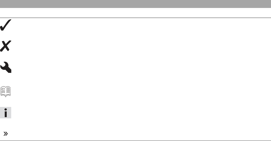
1.1 Symbols used
The meaning of specific symbols is described below.
Indicates an expected reaction (e.g. of a work step or a function).
Indicates an unexpected reaction (e.g. of a work step or a function).
All work marked with this symbol requires specialist knowledge and technical understanding. In the interest of your
own safety, have these jobs performed by an authorized KTM workshop. There, your motorcycle will be optimally
cared for by specially trained experts using the specialist tools required.
Indicates a page reference (more information is provided on the specified page).
Indicates information with more details or tips.
Indicates the result of a testing step.
1 MEANS OF REPRESENTATION 8
1.2 Formats used
The typographical formats used in this document are explained below.
Specific name Identifies a proprietary name.
Name®Identifies a protected name.
Brand™ Identifies a brand available on the open market.
Underlined terms Refer to technical details of the vehicle or indicate technical terms that are explained in the
glossary.

2 SAFETY ADVICE 9
2.1 Use definition
KTM sport motorcycles are designed and constructed to meet the normal demands of regular road operation but not for use on race
courses or offroad.
Info
The motorcycle is authorized for public road traffic in the homologous version only.
2.2 Misuse
The vehicle must only be used as intended.
Dangers can arise for people, property and the environment through use not as intended.
Any use of the vehicle beyond the intended and defined use constitutes misuse.
Misuse also includes the use of operating and auxiliary fluids which do not meet the required specification for the respective use.
2.3 Safety advice
A number of safety instructions need to be followed to operate the vehicle safely. Therefore, read this manual carefully. The safety instruc-
tions are highlighted in the text and are referred to at the relevant passages.
Info
The vehicle has various information and warning labels at prominent locations. Do not remove information/warning labels. If they
are missing, you or others may not recognize dangers and may therefore be injured.
2 SAFETY ADVICE 10
2.4 Degrees of risk and symbols
Danger
Indicates a danger that will immediately and invariably lead to fatal or serious permanent injury if the appropriate measures are not
taken.
Warning
Indicates a danger that is likely to lead to fatal or serious injury if the appropriate measures are not taken.
Caution
Indicates a danger that may lead to minor injuries if the appropriate measures are not taken.
Note
Indicates a danger that will lead to considerable machine and material damage if the appropriate measures are not taken.
Warning
Indicates a danger that will lead to environmental damage if the appropriate measures are not taken.
2.5 Tampering warning
Tampering with the noise control system is prohibited. Federal law prohibits the following acts or the causing thereof:
1 The removal or rendering inoperative by any person other than for purposes of maintenance, repair, or replacement, of any device or
element of design incorporated into any new vehicle for the purpose of noise control prior to its sale or delivery to the ultimate pur-
chaser or while it is in use, or
2 the use of the vehicle after such device or element of design has been removed or rendered inoperative by any person.
Among those acts presumed to constitute tampering are the acts listed below:
2 SAFETY ADVICE 11
1 Removal or puncturing of the main silencer, baffles, header pipes or any other components which conduct exhaust gases.
2 Removal or puncturing of parts of the intake system.
3 Lack of proper maintenance.
4 Replacing moving part of the vehicle, or parts of the exhaust or intake system, with parts other than those specified by the manufac-
turer.
2.6 Safe operation
Danger
Danger of accidents A rider who is not fit to ride poses a danger to him or herself and others.
–Do not operate the vehicle if you are not fit to ride due to alcohol, drugs or medication.
–Do not operate the vehicle if you are physically or mentally impaired.
Danger
Danger of poisoning Exhaust gases are toxic and inhaling them may result in unconsciousness and death.
–Always make sure there is sufficient ventilation when running the engine.
–Use an effective exhaust extraction system when starting or running the engine in an enclosed space.
Warning
Danger of burns Some vehicle components become very hot when the vehicle is operated.
–Do not touch any parts such as the exhaust system, radiator, engine, shock absorber, or brake system before the vehicle parts
have cooled down.
–Let the vehicle parts cool down before you perform any work on the vehicle.
Only operate the vehicle when it is in perfect technical condition, in accordance with its intended use, and in a safe and environmentally
compatible manner.
An appropriate driver's license is needed to ride the vehicle on public roads.
Have malfunctions that impair safety promptly eliminated by an authorized KTM workshop.
Adhere to the information and warning labels on the vehicle.
2 SAFETY ADVICE 12
2.7 Protective clothing
Warning
Risk of injury Missing or poor protective clothing presents an increased safety risk.
–Wear appropriate protective clothing such as helmet, boots, gloves as well as trousers and a jacket with protectors on all rides.
–Always wear protective clothing that is in good condition and meets the legal regulations.
In the interest of your own safety, KTM recommends that you only operate the vehicle while wearing protective clothing.
2.8 Work rules
Special tools are necessary for certain tasks. The tools are not contained in the vehicle but can be ordered under the number in parenthe-
ses. E.g.: bearing puller (15112017000)
During assembly, non-reusable parts (e.g. self-locking screws and nuts, seals and seal rings, O-rings, pins, lock washers) must be replaced
by new parts.
In some instances, a thread locker (e.g. Loctite®) is required. The manufacturer instructions for use must be followed.
After disassembly, clean the parts that are to be reused and check them for damage and wear. Change damaged or worn parts.
After you complete the repair or service work, check the operating safety of the vehicle.
2.9 Environment
If you use your motorcycle responsibly, you can ensure that problems and conflicts do not occur. To protect the future of the motorcycle
sport, make sure that you use your motorcycle legally, display environmental consciousness, and respect the rights of others.
When disposing of used oil, other operating and auxiliary fluids, and used components, comply with the laws and regulations of the
respective country.
Because motorcycles are not subject to the EU regulations governing the disposal of used vehicles, there are no legal regulations that per-
tain to the disposal of an end-of-life motorcycle. Your authorized KTM dealer will be glad to advise you.

2 SAFETY ADVICE 13
2.10 Owner's Manual
It is important that you read this Owner's Manual carefully and completely before making your first trip. The Owner's Manual contains use-
ful information and many tips on how to operate, handle, and maintain your motorcycle. Only then will you find out how to customize the
vehicle ideally for your own use and how you can protect yourself from injury.
Keep the Owner's Manual in an accessible place to enable you to refer to it as needed.
If you would like to know more about the vehicle or have questions on the material you read, please contact an authorized KTM dealer.
The Owner's Manual is an important component of the vehicle and must be handed over to the new owner if the vehicle is sold.
3 IMPORTANT NOTES 14
3.1 Manufacturer and implied warranty
The work specified in the service schedule may only be performed in an authorized KTM workshop and must be recorded in both the
Service & Warranty Booklet and in KTM Dealer.net, otherwise any warranty coverage will become void. Damage or secondary damage caused
by tampering with and/or conversions on the vehicle are not covered by the warranty.
Additional information on the manufacturer or implied warranty and the procedures involved can be found in the Service & Warranty Book-
let.
3.2 Operating and auxiliary substances
Warning
Environmental hazard Improper handling of fuel is a danger to the environment.
–Do not allow fuel to enter the groundwater, the soil, or the sewage system.
Use operating and auxiliary substances (such as fuel and lubricants) as specified in the Owner's Manual.
3.3 Spare parts, accessories
For your own safety, only use spare parts and accessory products that are approved and/or recommended by KTM and have them installed
by an authorized KTM workshop. KTM accepts no liability for other products and any resulting damage or loss.
Certain spare parts and accessory products are specified in parentheses in the descriptions. Your authorized KTM dealer will be glad to
advise you.
The current KTM PowerParts for your vehicle can be found on the KTM website.
International KTM Website: http://www.ktm.com

3 IMPORTANT NOTES 15
3.4 Service
A prerequisite for perfect operation and prevention of premature wear is that the service, care, and tuning work on the engine and chassis
is properly carried out as described in the Owner's Manual. Incorrect adjustment and tuning of the engine and chassis can lead to damage
and breakage of components.
Use of the vehicle under difficult conditions, such in rain, high heat or with a heavy load, can lead to considerably more rapid wear of
components such as the drive train, brake system, or suspension components. For this reason, it may be necessary to inspect or replace
parts before the next scheduled service.
It is imperative that you adhere to the stipulated run-in times and service intervals. If you observe these exactly, you will ensure a much
longer service life for your motorcycle.
3.5 Figures
The figures contained in the manual may depict special equipment.
In the interest of clarity, some components may be shown disassembled or may not be shown at all. It is not always necessary to disassem-
ble the component to perform the activity in question. Please follow the instructions in the text.
3.6 Customer service
Your authorized KTM dealer will be happy to answer any questions you may have on your vehicle and KTM.
A list of authorized KTM dealers can be found on the KTM website.
International KTM Website: http://www.ktm.com
4 VIEW OF VEHICLE 16
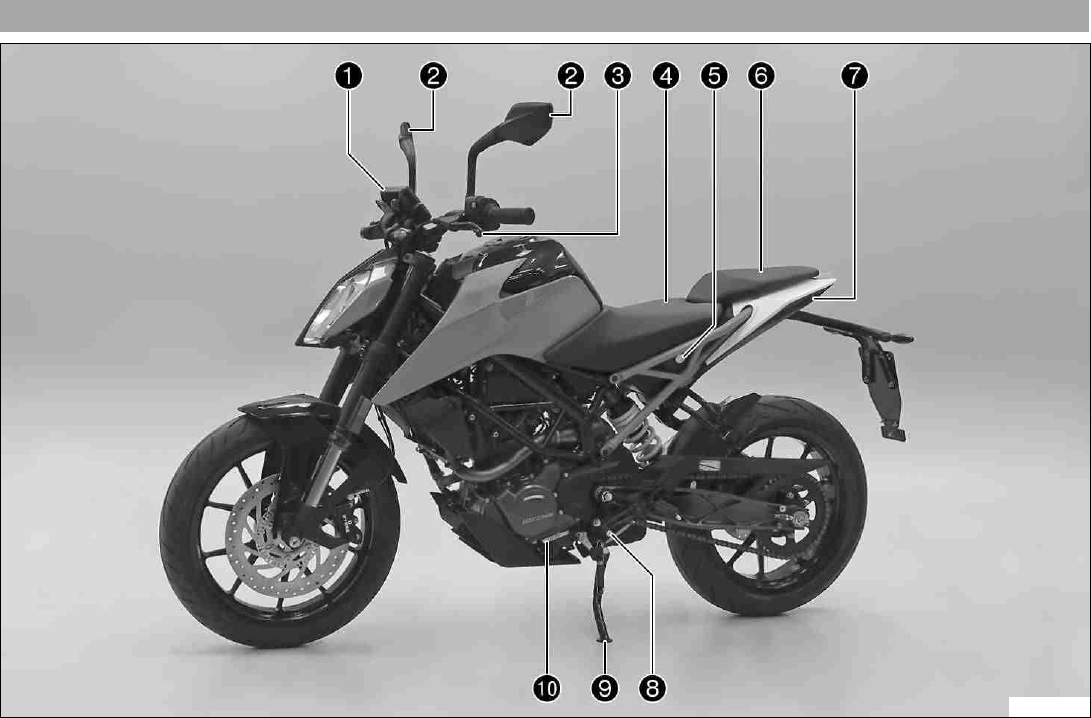
4.1 View of vehicle, front left (example)
F00781-10
4 VIEW OF VEHICLE 18
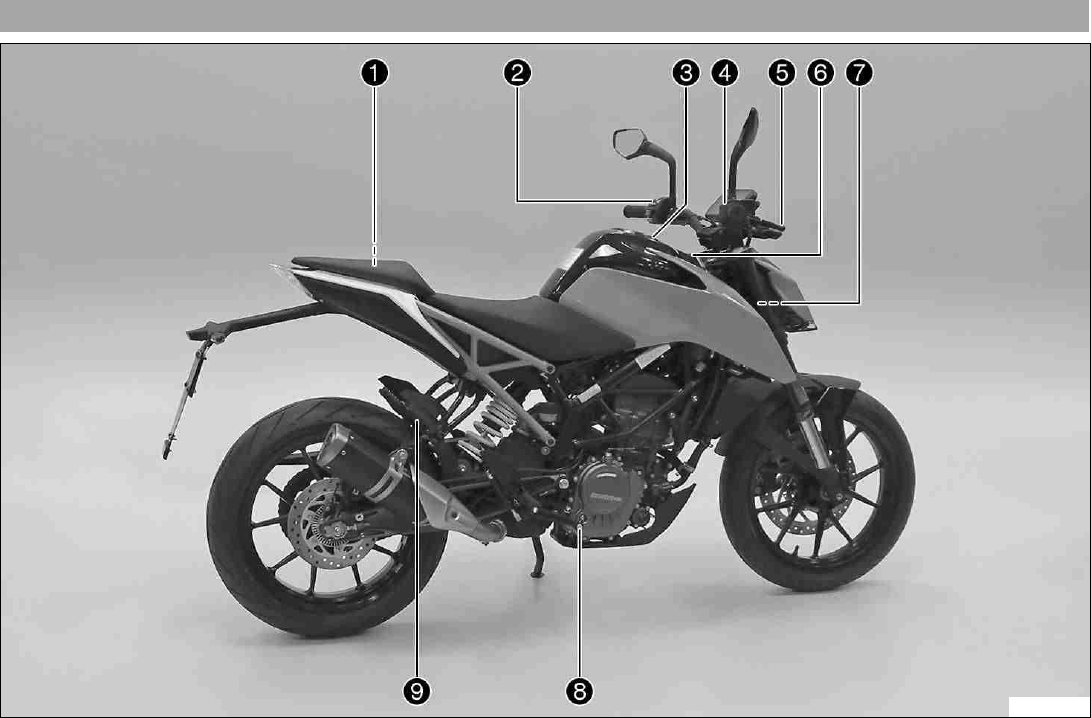
4.2 View of vehicle, rear right (example)
F00782-10
4 VIEW OF VEHICLE 19
1 Tool set ( p. 31)
2 Light switch ( p. 24)
2 Menu switch ( p. 24)
2 Turn signal switch ( p. 25)
2 Horn button ( p. 25)
3 Filler cap
4 Electric starter button ( p. 26)
4 Emergency OFF switch ( p. 26)
5 Hand brake lever ( p. 22)
6 Ignition/steering lock ( p. 27)
7 Chassis number ( p. 20)
7 Type label ( p. 20)
8 Foot brake lever ( p. 33)
9 Passenger footrests ( p. 32)
5 SERIAL NUMBERS 20
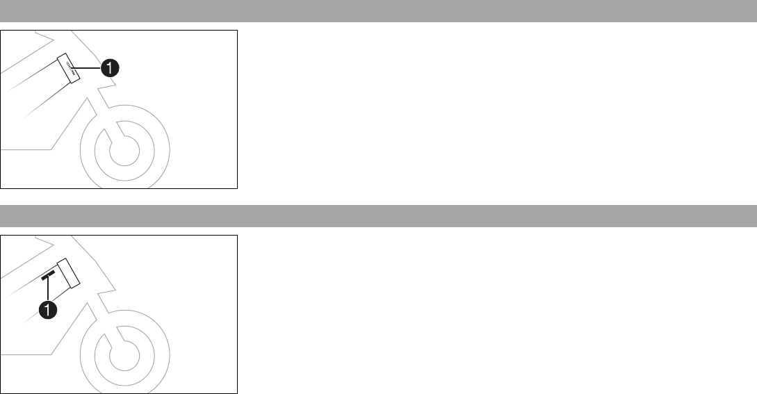
5.1 Chassis number
0
0
11
402408-10
The chassis number 1is stamped on the right side of the steering head.
5.2 Type label
0
0
11
402174-10
The type label 1is on the right of the frame behind the steering head.
5 SERIAL NUMBERS 21
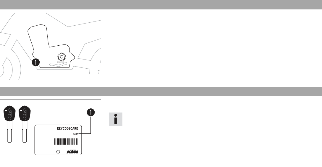
5.3 Engine number
402486-10
The engine number 1is stamped on the left side of the engine under the engine sprocket.
5.4 Key number
402245-10
The key number 1can be found on the KEYCODECARD.
Info
You need the key number to order a spare key. Keep the KEYCODECARD in a safe
place.
6 CONTROLS 22
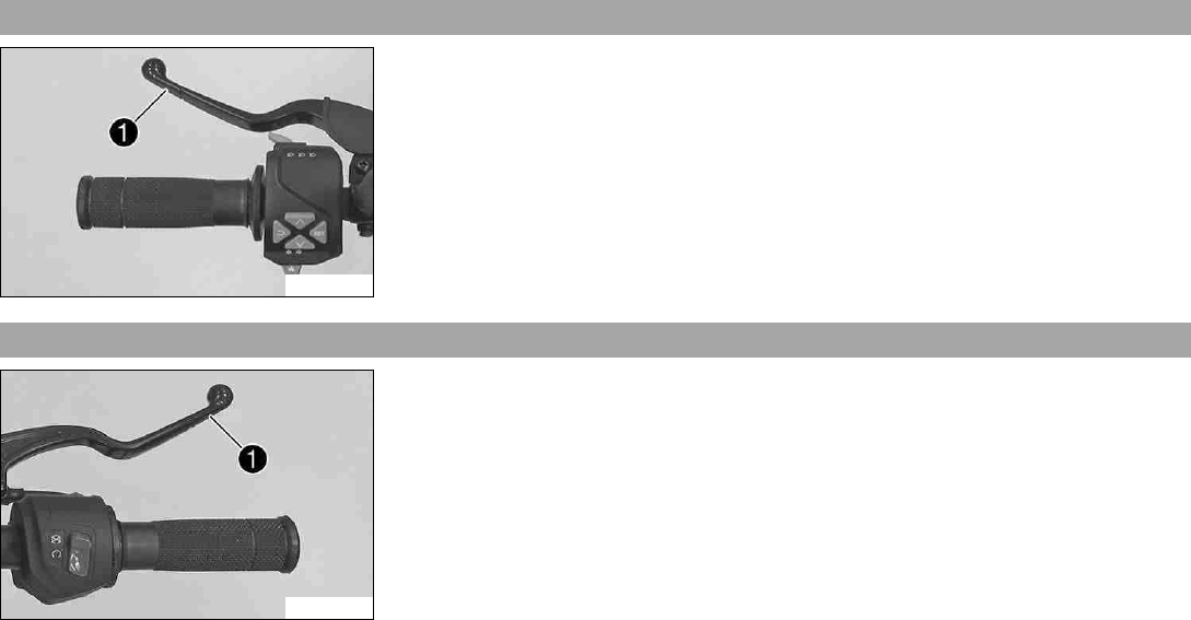
6.1 Clutch lever
F00717-10
The clutch lever 1is fitted on the left side of the handlebar.
6.2 Hand brake lever
F00718-10
The hand brake lever 1is fitted on the right side of the handlebar.
The front brake is engaged using the hand brake lever.
6 CONTROLS 23
6.3 Throttle grip
F00718-11
The throttle grip 1is fitted on the right side of the handlebar.
6.4 Switches on the left side of the handlebar
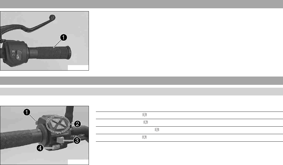
6.4.1 Combination switch
The combination switch is fitted on the left side of the handlebar.
F00720-10
Overview of the left combination switch
1 Light switch ( p. 24)
2 Menu switch ( p. 24)
3 Turn signal switch ( p. 25)
4 Horn button ( p. 25)
6 CONTROLS 24
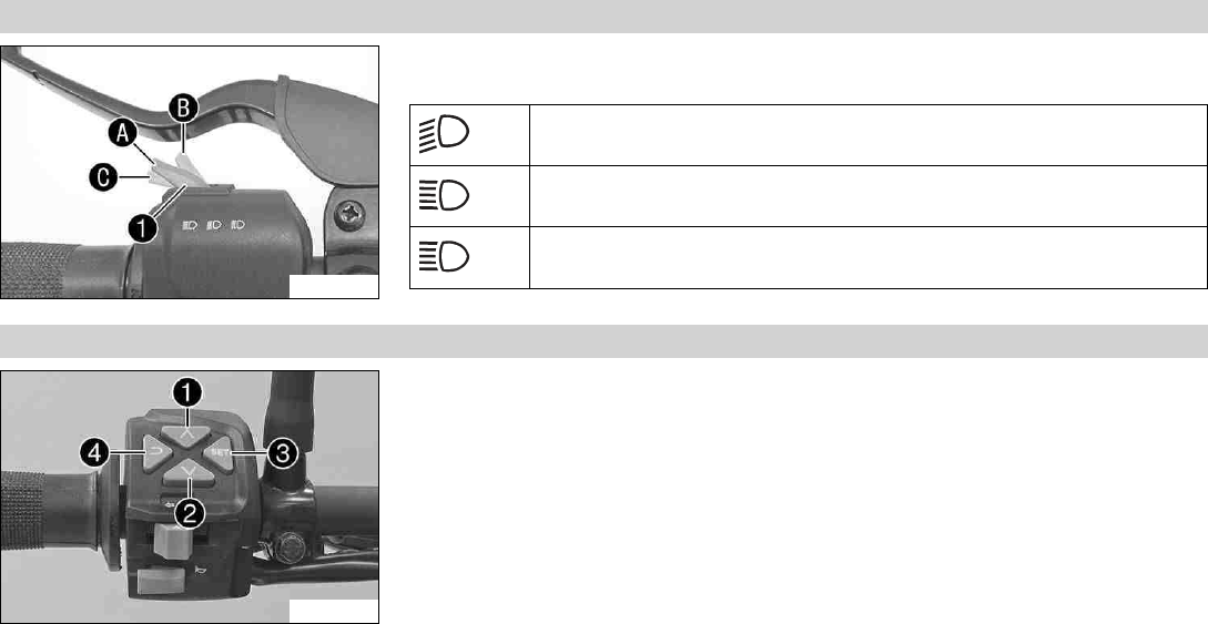
6.4.2 Light switch
F00719-10
Light switch 1is fitted on the left side of the handlebar.
Possible states
Low beam on –Light switch in position A. In this position, the low beam
and the tail light are switched on.
High beam on –Push the light switch to position B. In this position, the
high beam and the tail light are switched on.
Headlight flasher –Push the light switch into position C.
6.4.3 Menu switch
F00721-10
The menu switch is fitted in the middle of the left combination switch.
The menu buttons are used to control the display on the combination instrument.
Button 1is the UP button.
Button 2is the DOWN button.
Button 3is the SET button.
Button 4is the BACK button.
6 CONTROLS 25
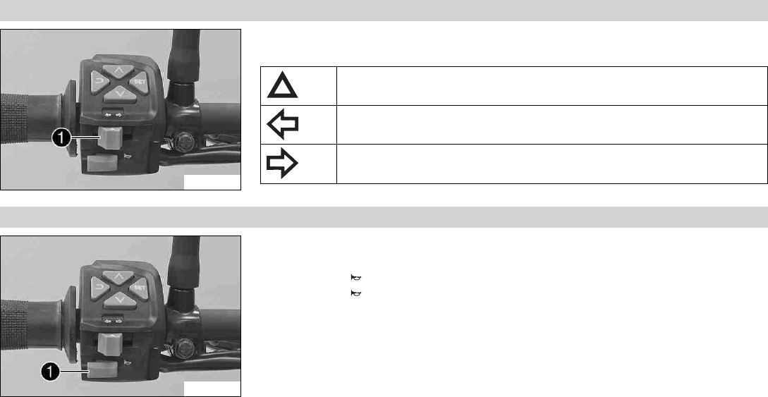
6.4.4 Turn signal switch
F00721-11
Turn signal switch 1is fitted on the left side of the handlebar.
Possible states
Turn signal off –Turn signal switch pushed toward the switch housing.
Left turn signal, on –Turn signal switch pressed to the left. The turn signal
switch returns automatically to the central position after use.
Right turn signal, on –Turn signal switch pressed to the right. The turn
signal switch returns automatically to the central position after use.
6.4.5 Horn button
F00721-12
The horn button 1is fitted on the left side of the handlebar.
Possible states
• Horn button in neutral position
• Horn button pressed –The horn is operated in this position.
6 CONTROLS 26
6.5 Switches on the right side of the handlebar
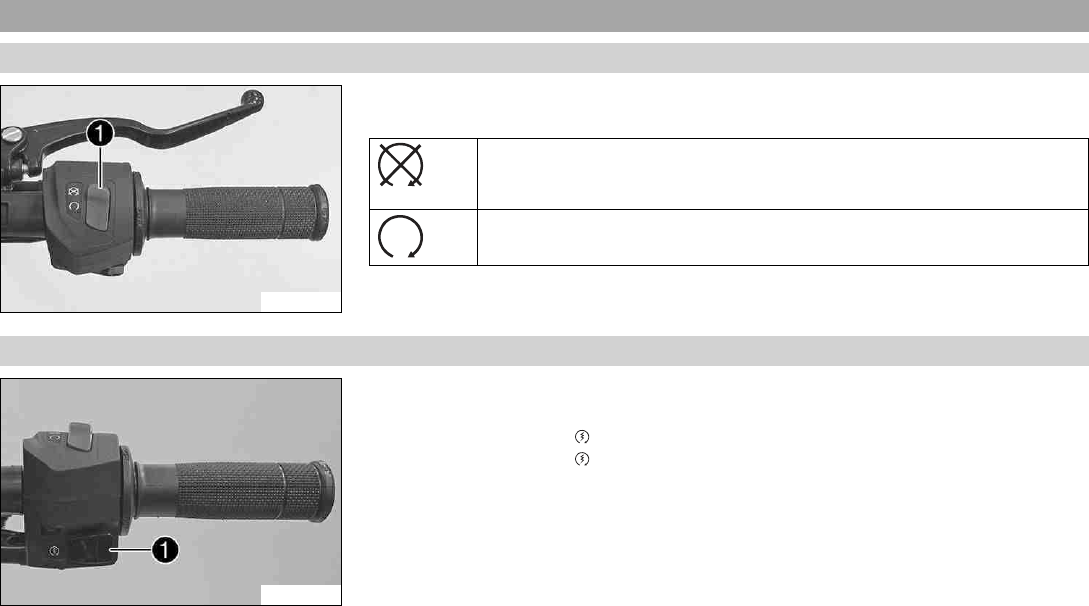
6.5.1 Emergency OFF switch
F00722-10
The emergency OFF switch 1is fitted on the right side of the handlebar.
Possible states
Emergency OFF switch off –In this position, the ignition circuit is
interrupted, a running engine stops, and a non-running engine cannot be
started.
Emergency OFF switch on –This position is required for operation; the igni-
tion circuit is closed.
6.5.2 Electric starter button
F00723-10
The electric starter button 1is fitted on the right side of the handlebar.
Possible states
• Electric starter button in basic position
• Electric starter button pressed –In this position, the electric starter is actuated.
6 CONTROLS 27
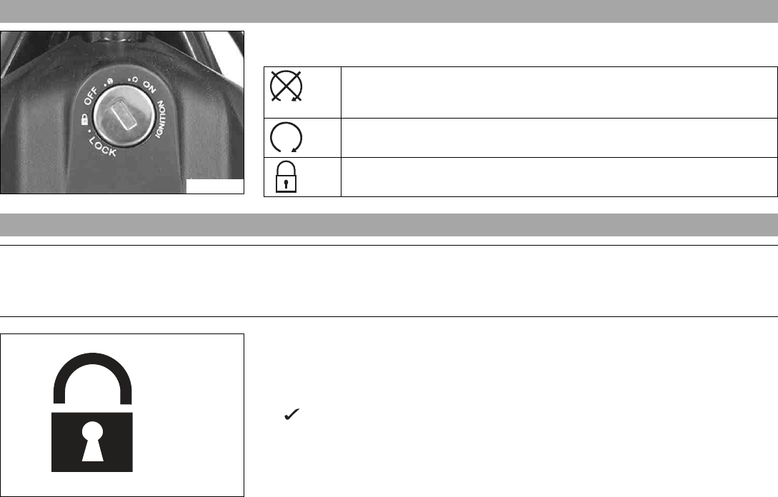
6.6 Ignition/steering lock
F00724-01
The ignition/steering lock is in front of the upper triple clamp.
Possible states
Ignition off OFF –In this position, the ignition circuit is interrupted, a run-
ning engine stops, and a non-running engine will not start. The ignition key
can be removed.
Ignition on ON –In this position, the ignition circuit is closed and the
engine can be started.
Steering locked LOCK –In this position, the ignition circuit is interrupted
and the steering locked. The ignition key can be removed.
6.7 Locking the steering
Note
Danger of damage The parked vehicle can roll away or fall over.
–Park the vehicle on a firm and level surface.
400732-01
–Park the vehicle.
–Turn the handlebar all the way to the left.
–Insert the key into the ignition/handlebar lock, press in, and turn to the left. Remove
the key.
Steering is no longer possible.
6 CONTROLS 28
6.8 Unlocking the steering
400731-01
–Insert the key into the ignition/handlebar lock, press in, and turn to the right. Remove
the key.
You can now steer the bike again.
6.9 Opening the filler cap
Danger
Fire hazard Fuel is highly flammable.
The fuel in the fuel tank expands when warm and can escape if overfilled.
–Do not refuel the vehicle in the vicinity of open flames or lit cigarettes.
–Switch off the engine for refueling.
–Make sure that no fuel is spilled; particularly not on hot parts of the vehicle.
–If any fuel is spilled, wipe it off immediately.
–Observe the specifications for refueling.
6 CONTROLS 29
Warning
Danger of poisoning Fuel is poisonous and a health hazard.
–Avoid skin, eye and clothing contact with fuel.
–Immediately consult a doctor if you swallow fuel.
–Do not inhale fuel vapors.
–In case of skin contact, rinse the affected area with plenty of water.
–Rinse the eyes thoroughly with water, and consult a doctor in case of fuel contact with the eyes.
–Change your clothing in case of fuel spills on them.
–Keep fuels correctly in a suitable canister, and out of the reach of children.
Warning
Environmental hazard Improper handling of fuel is a danger to the environment.
–Do not allow fuel to enter the groundwater, the soil, or the sewage system.
F00874-10
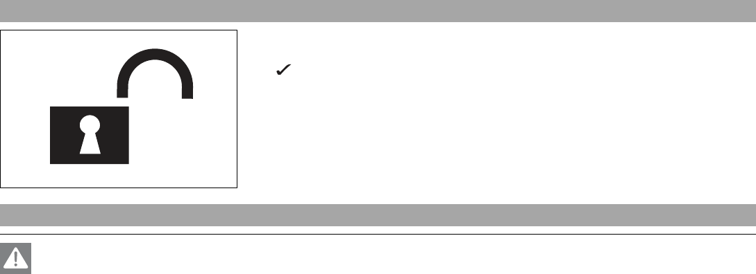
–Lift the cover 1of the filler cap and insert the ignition key in the lock.
Note
Danger of damage The ignition key may break if overloaded.
Damaged ignition keys must be replaced.
–Push down on the filler cap to take pressure off the ignition key.
–Turn the ignition key 90° clockwise.
–Open the filler cap.
–Remove the ignition key.
6 CONTROLS 30
6.10 Closing the filler cap
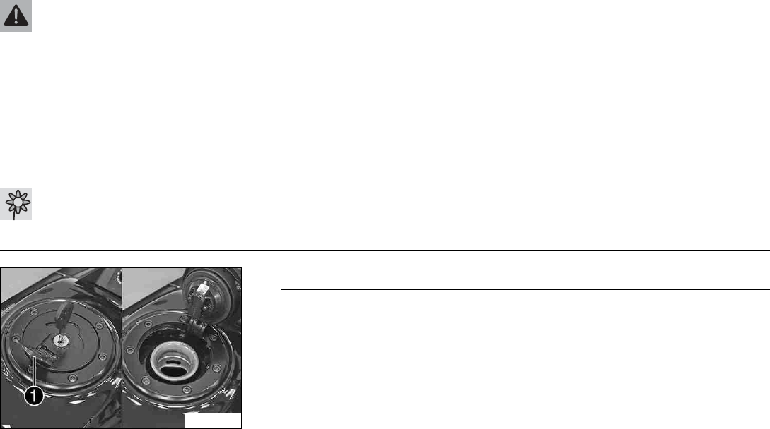
F00875-01
Warning
Fire hazard Fuel is highly flammable, toxic and a health hazard.
–Check the filler cap is locked correctly after closing.
–Change your clothing in case of fuel spills on them.
–Rinse the affected area immediately with plenty of water in the event of con-
tact with the skin.
–Close the filler cap.
–Push down the filler cap until the lock engages.
6.11 Seat lock
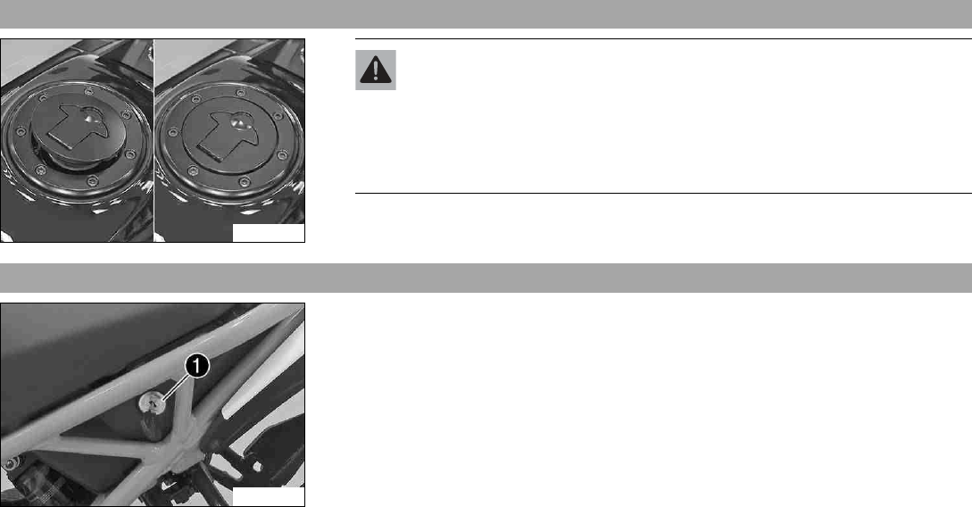
F00728-10
The seat lock 1is located to the left of the seat.
The seat lock can be unlocked using the ignition key.
6 CONTROLS 31
6.12 Tool set
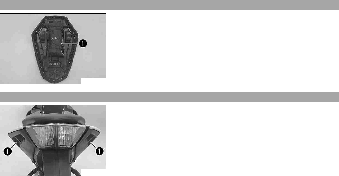
F00729-10
The tool set 1is located under the passenger seat.
6.13 Grab handles
F00741-10
The grab handles 1are used for moving the motorcycle around.
If you carry a passenger, the passenger can hold onto the grab handles during the trip.
6 CONTROLS 32
6.14 Passenger footrests
F00731-10
The passenger footrests can be folded in and out.
Possible states
• Passenger footrests folded up –For operation without a passenger.
• Passenger footrests folded down –For operation with a passenger.
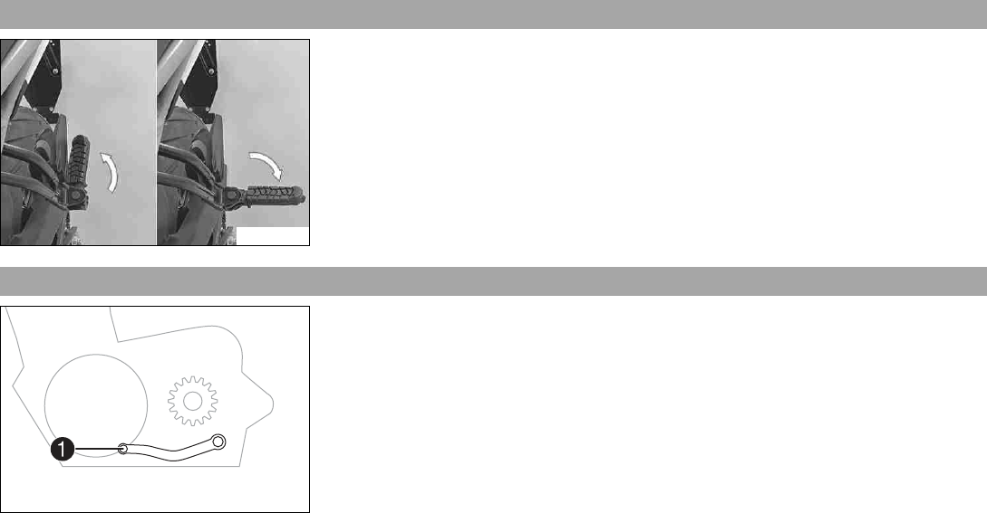
6.15 Shift lever
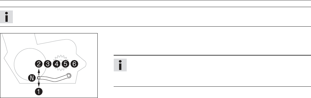
401950-10
Shift lever 1is mounted on the left side of the engine.
6 CONTROLS 33
401950-11
The gear positions can be seen in the photograph.
The neutral or idle position is between the first and second gears.
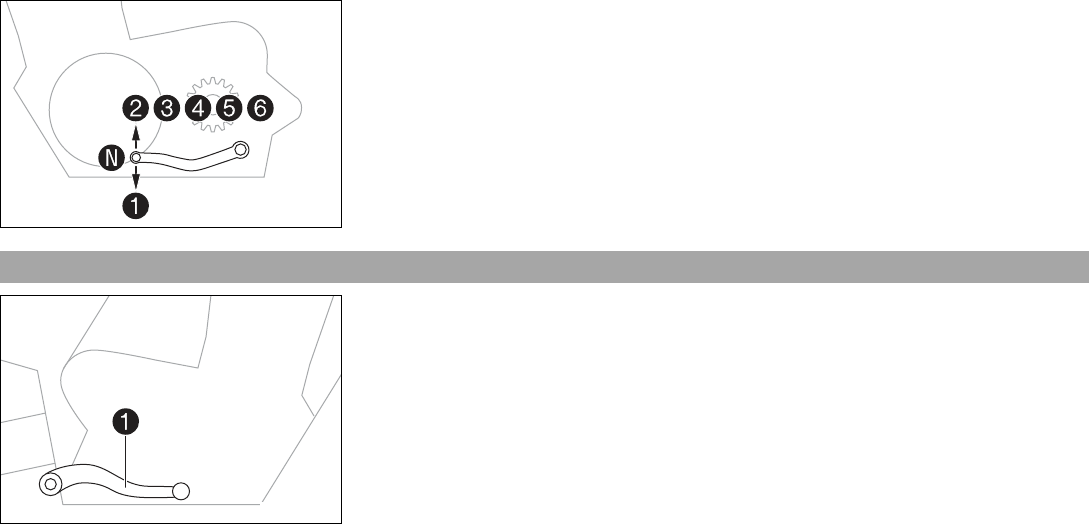
6.16 Foot brake lever
402177-10
Foot brake lever 1is located in front of the right footrest.
The foot brake lever is used to activate the rear brake.
6 CONTROLS 34
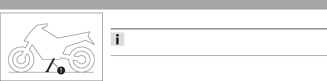
6.17 Side stand
402029-10
The side stand 1is on the left side of the vehicle.
The side stand is used to park the motorcycle.
Info
The side stand must be folded up during motorcycle use.
Side stand is coupled with the safety start system; see the riding instructions.
Possible states
• Side stand folded out –The vehicle can be leaned on the side stand. The safety start
system is active.
• Side stand folded in –This position is mandatory for all trips. The safety start system
is inactive.
7 COMBINATION INSTRUMENT 35
7.1 Combination instrument
402800-10
The combination instrument is attached in front of the handlebar.
The combination instrument is divided into two function areas.
1indicator lamps ( p. 38)
Display 2
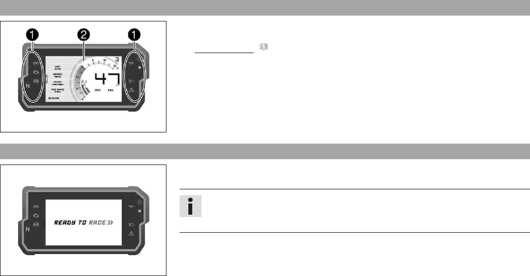
7.2 Activation and test
F00876-01
Activation
The combination instrument is activated when the ignition is switched on.
Info
The brightness of the displays is controlled by a brightness sensor in the combina-
tion instrument.
Test
The welcome text appears on the display and the indicator lamps are briefly activated for a
function test.
7 COMBINATION INSTRUMENT 36
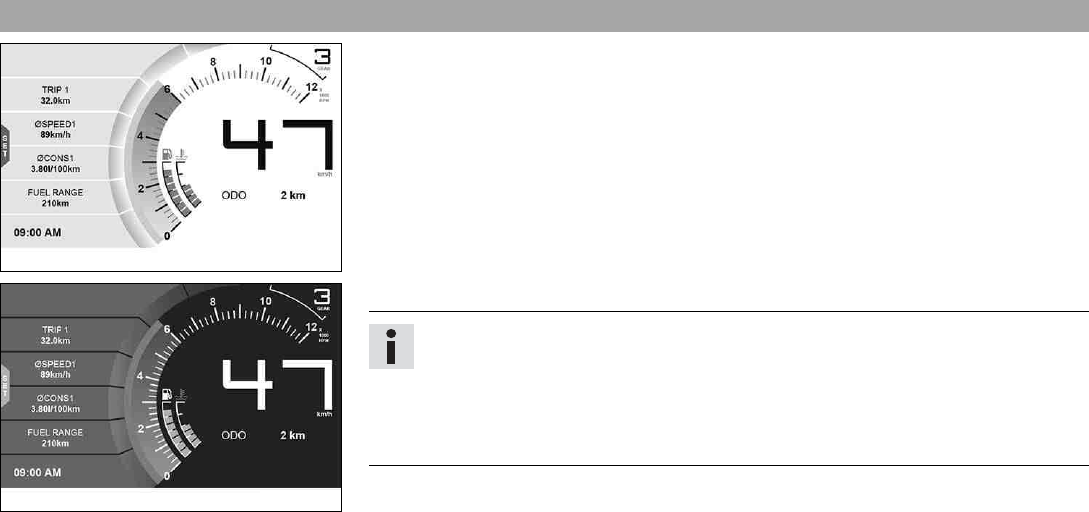
7.3 Day-Night mode
402803-01
Day mode is shown in a bright color.
402804-01
Night mode is shown in a dark color.
Info
The light sensor in the combination instrument measures the brightness of the envi-
ronment and automatically switches the display to day or night mode. The display
is brightened, darkened or switched to the other mode depending on the brightness
measured by the light sensor.
The display mode cannot be changed manually.
7 COMBINATION INSTRUMENT 37
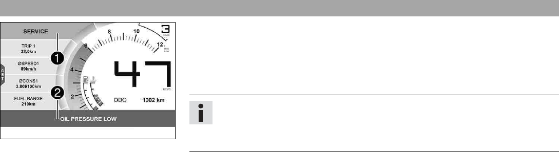
7.4 Warning notes
F00904-10
Warning notes appear on the top and/or bottom edge of the display, these are marked yel-
low or red depending on their relevance.
Yellow warning notes 1indicate errors or information which requires prompt intervention
or an adjustment to the riding style.
Red warning notes 2indicate errors or information which requires immediate interven-
tion.
Info
Warning notes are cleared by pressing any button.
All existing warning notes are displayed in the Warning menu until these are no
longer active.
7 COMBINATION INSTRUMENT 38
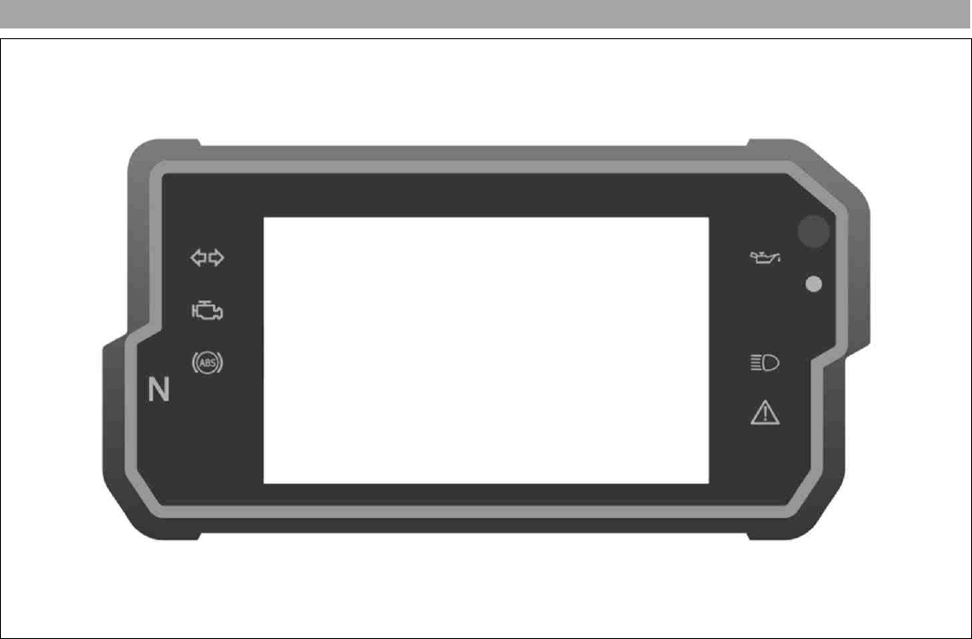
7.5 Indicator lamps
F00900-01
7 COMBINATION INSTRUMENT 39
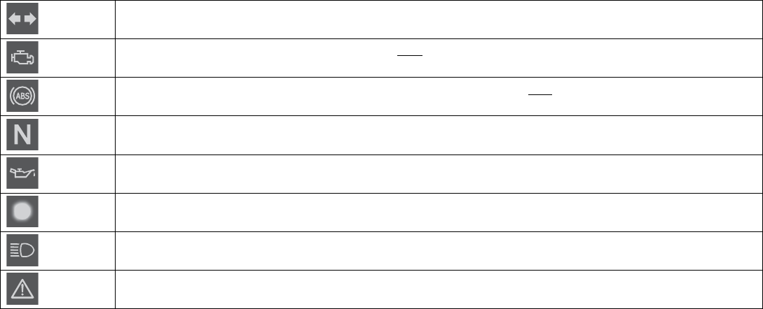
The indicator lamps offer additional information about the operating state of the motorcycle.
When the ignition is switched on, all indicator lamps light up briefly.
Possible states
The turn signal indicator lamp flashes green simultaneously with the turn signal –The turn signal is switched on.
Malfunction indicator lamp lights up yellow –The OBD has detected an emission- or safety-critical fault.
ABS indicator lamp lights up yellow –Status or error messages relating to ABS.
The idle indicator lamp lights up green –The transmission is in idle.
The oil pressure warning lamp lights up red –The oil pressure is too low.
Alarm system indicator lamp flashes red –Status message on the alarm system (optional).
The high beam indicator lamp lights up blue –The high beam is switched on.
The general warning lamp lights up yellow –An operating safety (warning) message was detected. This is also
shown on the display.
7 COMBINATION INSTRUMENT 40
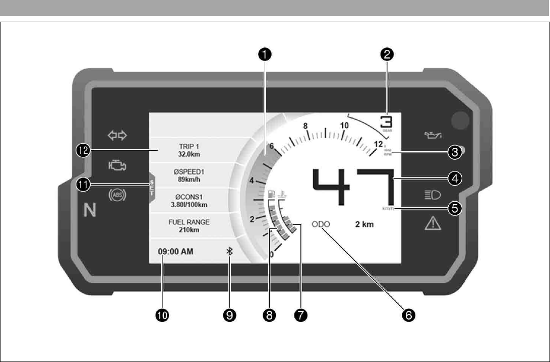
7.6 Display
F00877-10

7 COMBINATION INSTRUMENT 41
1 Speed ( p. 42)
1 Shift warning light ( p. 43)
The shift warning light is integrated in the tachometer display.
2 Gear display
3 Unit for the speed display
4 Speed ( p. 44)
5 Unit for the speedometer
6ODO display ( p. 44)
7 Coolant temperature indicator ( p. 45)
8 Fuel level display ( p. 45)
9Bluetooth®(optional)
10 Time ( p. 46)
11 SET
Only shown where the menu overview is closed.
12 Favourites display ( p. 46)
7 COMBINATION INSTRUMENT 42
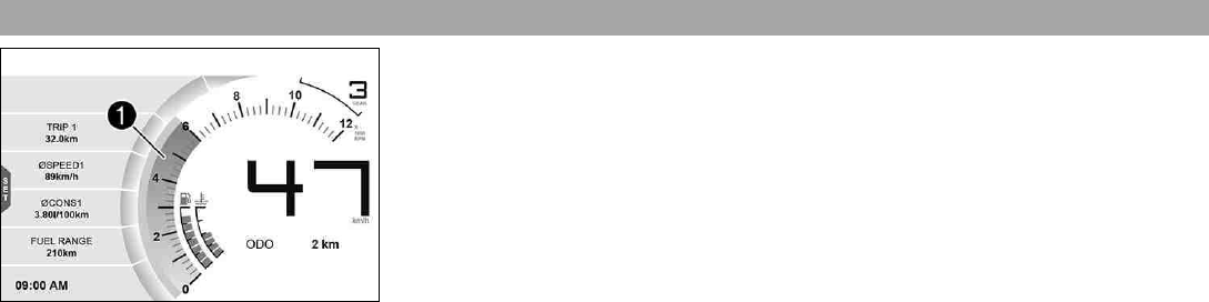
7.7 Speed
F00878-12
The speed 1is measured in revolutions per minute.
7 COMBINATION INSTRUMENT 43
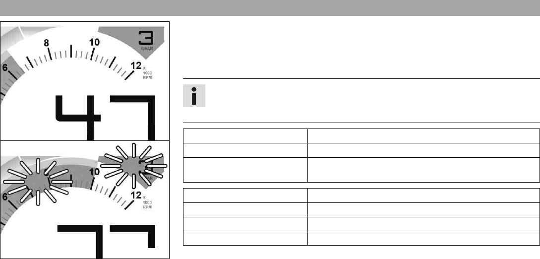
7.8 Shift warning light
402809-01
The shift warning light is integrated in the tachometer display.
In the Shift Light menu, the engine speed for the shift warning light can be set. The shift
warning light is always active during the running-in phase (up to 1,000 km / 621 mi). The
shift warning light can only be deactivated, and the values for RPM1 and RPM2 can only be
adjusted after this. The shift warning light lights up red at RPM1and flashes red at RPM2.
Info
In sixth-gear, the shift warning light is deactivated when the engine is warm after
the first service.
Coolant temperature ≤35 °C (≤95 °F)
ODO < 1,000 km (< 620 mi)
The shift warning light always
lights up at
6,500 rpm
Coolant temperature > 35 °C (> 95 °F)
ODO > 1,000 km (> 620 mi)
RPM1 shift warning light lights up
RPM2 shift warning light flashes
7 COMBINATION INSTRUMENT 44
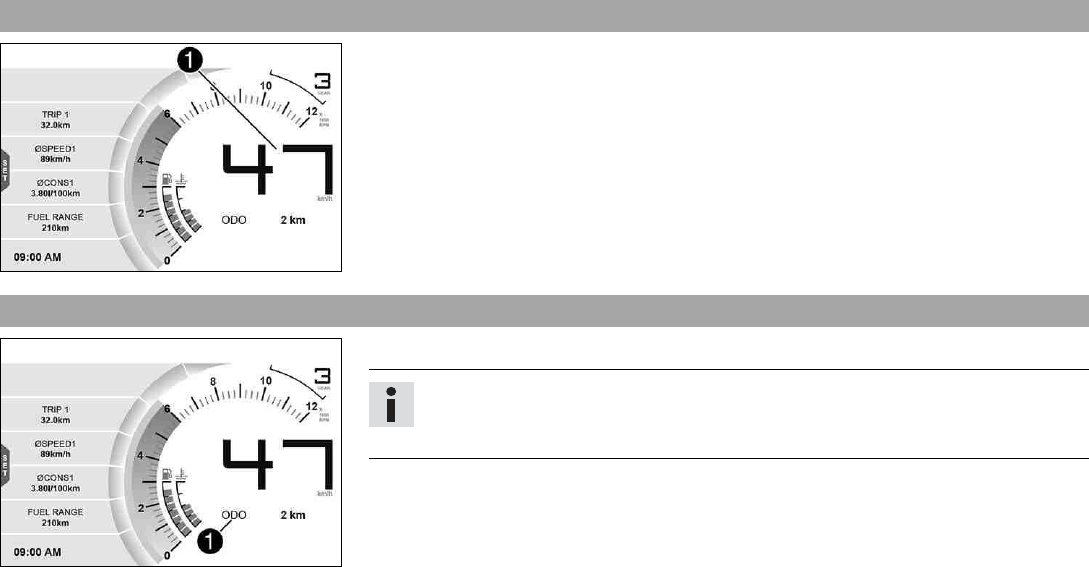
7.9 Speed
402806-10
Speed 1is shown in kilometers per hour km/h or in miles per hour mph.
7.10 ODO display
402806-12
The total distance covered ODO is shown in area 1of the display.
Info
This value is retained, even if the battery is disconnected from the vehicle or the
fuse blows.
7 COMBINATION INSTRUMENT 45
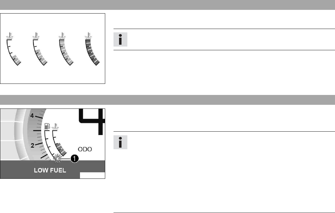
7.11 Coolant temperature indicator
402808-01
The coolant temperature indicator consists of bars. The more bars that light up, the hotter
the coolant.
Info
When all bars light up, the following warning note ENGINE TEMP HIGH appears.
Possible states
• The engine is cold –Up to three bars light up.
• Engine warm –Four to five bars light up.
• Engine hot –Six to eight bars light up.
• Engine very hot –All eight bars light up red.
7.12 Fuel level display
402807-10
The fuel tank contents are shown in area 1of the display.
The fuel level indicator consists of bars. The more bars are lit, the more fuel is in the fuel
tank.
Info
If the fuel level is getting low, the last segment flashes red and the following warn-
ing note also appears LOW FUEL.
The fuel level is displayed with a slight delay to prevent the indicator from con-
stantly moving while riding.
The fuel level display is not updated while the side stand is folded out or the emer-
gency off switch is switched off.
Once the side stand is folded up and emergency OFF switch is switched on, the fuel
level display is next updated after 2 minutes.
The fuel level display flashes if the combination instrument does not receive a signal
from the fuel level sensor.
7 COMBINATION INSTRUMENT 46
7.13 Time
402806-13
The time is shown in area 1of the display.
The time is displayed in 24 hour format in all languages except for EN-US. The time is dis-
played in 12 hour format if the language is set to EN-US.
The time can be configured in the Clock/Date menu.
Info
The time must be reset after the battery was disconnected or the fuse was removed.
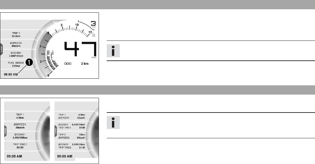
7.14 Favourites display
402811-01
Up to eight items of information are shown in the Favourites display.
The Favourites display can be freely configured in the Favourites menu.
Info
One to four items of information selected are displayed on two lines. Five to eight
items of information selected are displayed on a single line.
7 COMBINATION INSTRUMENT 47
7.15 Quick Selector 1 display
F00801-01
When the menu is closed, the Quick Selector 1 menu is opened by pressing the UP button.
Press the BACK button to close Quick Selector 1.
Info
The Quick Selector 1 can be configured in the Quick Selector 1 menu. Any informa-
tion can be selected.
7.16 Quick Selector 2 display
F00802-01
When the menu is closed, the Quick Selector 2 menu is opened by pressing the DOWN but-
ton.
Press the BACK button to close Quick Selector 2.
Info
The Quick Selector 2 can be configured in the Quick Selector 2 menu. Any informa-
tion can be selected.
7 COMBINATION INSTRUMENT 48
7.17 Menu
F00905-10
Info
Press the SET button 1in the standard display to open the menu.
Navigate through the menu using the UP button 2or the DOWN button 3.
Press the BACK button 4to close the current menu or the menu overview.
7.17.1 KTM MY RIDE (optional)
F00804-01
Condition
• The motorcycle is stationary.
• Function KTM MY RIDE activated (optional).
• Function Bluetooth®activated.
–Press the SET button when the menu is closed.
–Press the UP or DOWN button until KTM MY RIDE is marked. Press the SET button to
open the menu.
In KTM MY RIDE a suitable cellphone can be paired with the combination instrument via
Bluetooth®.
Info
Not every cellphone is suitable for pairing with the combination instrument.
The standard Bluetooth®2.1 must be supported.
7 COMBINATION INSTRUMENT 49
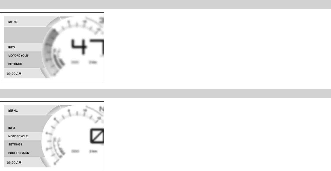
7.17.2 Info
F00804-02
–Press the SET button when the menu is closed.
–Press the UP or DOWN button until Info is marked. Press the SET button to open the
menu.
General information can be accessed in Info.
7.17.3 Motorcycle
F00804-03
Condition
• The motorcycle is stationary.
–Press the SET button when the menu is closed.
–Press the UP or DOWN button until Motorcycle is marked. Press the SET button to open
the menu.
The vehicle drive mode can be configured in Motorcycle.
7 COMBINATION INSTRUMENT 50
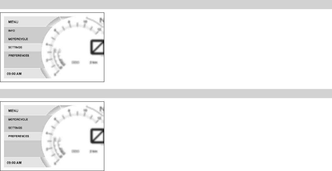
7.17.4 Settings
F00804-04
Condition
• The motorcycle is stationary.
–Press the SET button when the menu is closed.
–Press the UP or DOWN button until Settings is marked. Press the SET button to open the
menu.
Favorites and quick selection can be configured in Settings.
7.17.5 Preferences
F00804-05
Condition
• The motorcycle is stationary.
–Press the SET button when the menu is closed.
–Press the UP or DOWN button until Preferences is marked. Press the SET button to open
the menu.
The combination instrument display can be configured in Preferences. Settings can be
made for units or various values. Several functions can be enabled or disabled.
7 COMBINATION INSTRUMENT 51
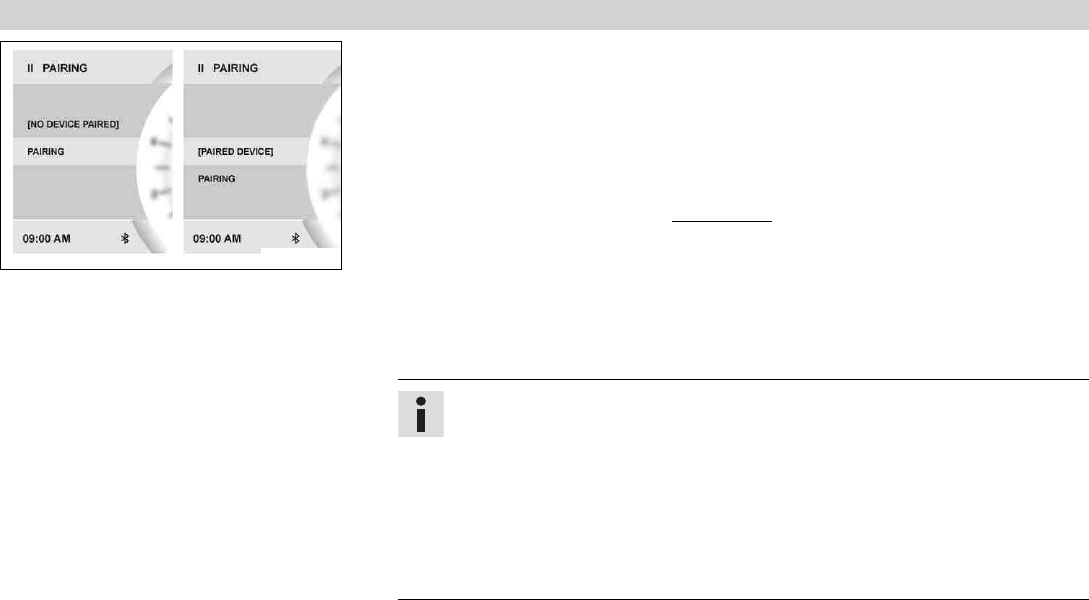
7.17.6 Pairing (optional)
F00842-01
Condition
• The motorcycle is stationary.
• Function KTM MY RIDE activated (optional).
• Function Bluetooth®activated.
• The Bluetooth®function should also be activated in the device to be paired.
–Press the SET button when the menu is closed.
–Press the UP or DOWN button until KTM MY RIDE is marked. Press the SET button to
open the menu.
–Press the UP or DOWN button until Pairing is marked. Press the SET button to open the
menu.
–Press the UP or DOWN button until Pairing is marked. Press the SET button to pair a
suitable cellphone with the combination instrument via Bluetooth®.
–Confirmation of the Passkey successfully completes the pairing.
Info
When a suitable cellphone has been successfully paired, the name of the paired
cellphone is displayed.
Press the UP or DOWN button until paired device is marked on the display. The
paired device can be deleted by pressing the SET button.
The device most recently linked is automatically paired with the combination
instrument when Bluetooth®is switched on and as soon as this device is in range
and has not been previously deleted.
Not every cellphone is suitable for pairing with the combination instrument.
7 COMBINATION INSTRUMENT 52
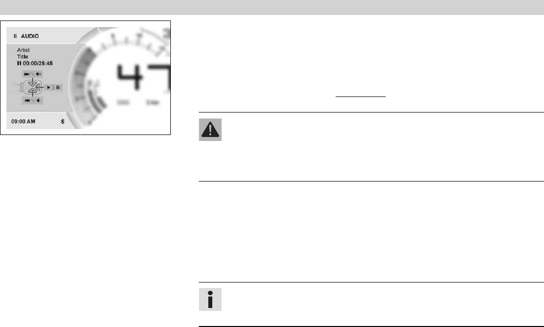
7.17.7 Audio (optional)
F00837-01
Condition
• Function KTM MY RIDE activated (optional).
• Function Bluetooth®activated.
• The Bluetooth®function should also be activated in the device to be paired.
–Press the SET button when the menu is closed.
–Press the UP or DOWN button until KTM MY RIDE is marked. Press the SET button to
open the menu.
Warning
Danger of accidents Headphone volume which is too high distracts attention
from traffic activity.
–Always select headphone volume which is low enough for you to still clearly
hear acoustic signals.
–Press the UP or DOWN button until Audio is marked. Press the SET button to open the
menu.
–Press and hold the UP button to increase the audio volume.
–Press and hold the DOWN button to reduce the audio volume.
–Press the UP button briefly to change to the next audio track.
–Press the DOWN button briefly to change to the previous audio track.
–Press the SET button to play or pause the audio track.
Info
The audio function can be added to Quick Selector 1 or Quick Selector 2 for eas-
ier operation.
7 COMBINATION INSTRUMENT 53
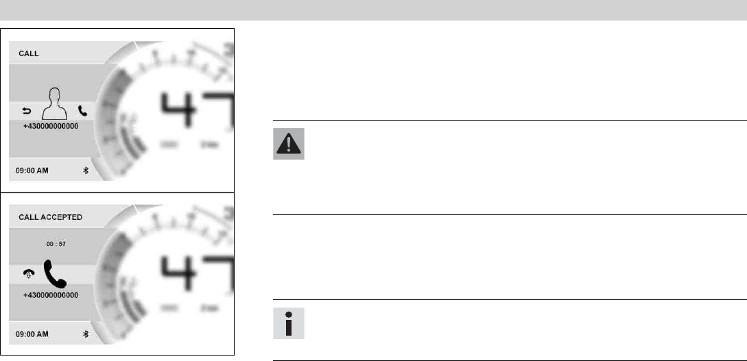
7.17.8 Telephony (optional)
F00841-01
Condition
• Function KTM MY RIDE activated (optional).
• Function Bluetooth®activated.
• The Bluetooth®function should also be activated in the device to be paired.
• Headset linked with appropriate cellphone.
Warning
Danger of accidents Headphone volume which is too high distracts attention
from traffic activity.
–Always select headphone volume which is low enough for you to still clearly
hear acoustic signals.
–Press the SET button to accept an incoming call.
–Press the BACK button to reject an incoming call.
–Press and hold the UP button to increase the audio volume.
–Press and hold the DOWN button to reduce the audio volume.
Info
The call duration and contact are displayed. Depending on the cellphone
settings, the contact is shown by name.
7 COMBINATION INSTRUMENT 54
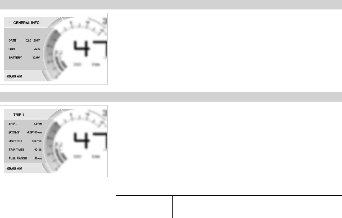
7.17.9 General Info
F00806-01
–Press the SET button when the menu is closed.
–Press the UP or DOWN button until Info is marked. Press the SET button to open the
menu.
–Press the UP or DOWN button until General Info is marked. Press the SET button to open
the menu.
Date shows the date.
ODO shows the total distance covered.
Battery indicates the battery voltage.
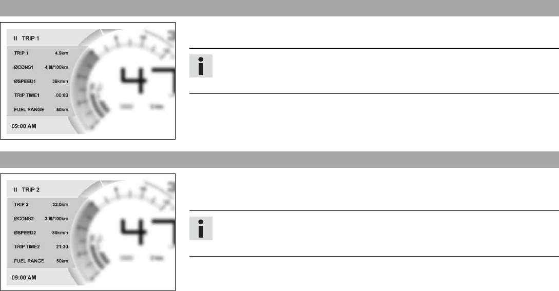
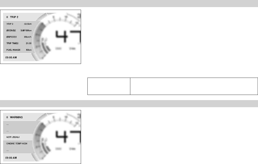
7.17.10 Trip 1
F00807-01
–Press the SET button when the menu is closed.
–Press the UP or DOWN button until Info is marked. Press the SET button to open the
menu.
–Press the UP or DOWN button until Trip 1 is marked. Press the SET button to open the
menu.
Trip 1 shows the distance since the last reset, such as between two refueling stops. Trip 1 is
running and counts up to 9999.
ØCons1 indicates the average fuel consumption based on Trip 1.
ØSpeed1 indicates the average speed based on Trip 1 and Trip Time1.
Trip Time1 shows the journey time on the basis of Trip 1 and runs as soon as a speed signal
is received.
Fuel Range indicates the possible distance you can cover with the fuel reserve.
Press and hold the
SET button for 3-5
seconds.
All entries in the Trip 1 menu are reset.
7 COMBINATION INSTRUMENT 55
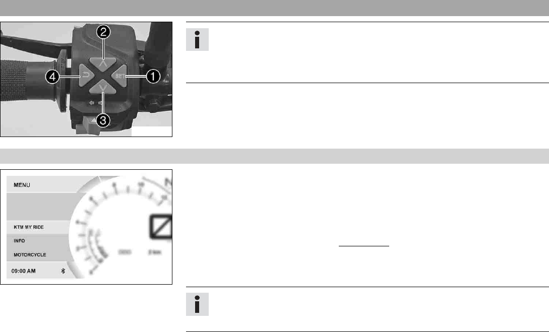
7.17.11 Trip 2
F00808-01
–Press the SET button when the menu is closed.
–Press the UP or DOWN button until Info is marked. Press the SET button to open the
menu.
–Press the UP or DOWN button until Trip 2 is marked. Press the SET button to open the
menu.
Trip 2 shows the distance since the last reset, such as between two refueling stops. Trip 2 is
running and counts up to 9999.
ØCons2 indicates the average fuel consumption based on Trip 2.
ØSpeed2 indicates the average speed based on Trip 2 and Trip Time2.
Trip Time2 shows the journey time on the basis of Trip 2 and runs as soon as a speed signal
is received.
Fuel Range indicates the possible distance you can cover with the fuel reserve.
Press and hold the
SET button for 3-5
seconds.
All entries in the Trip 2 menu are reset.
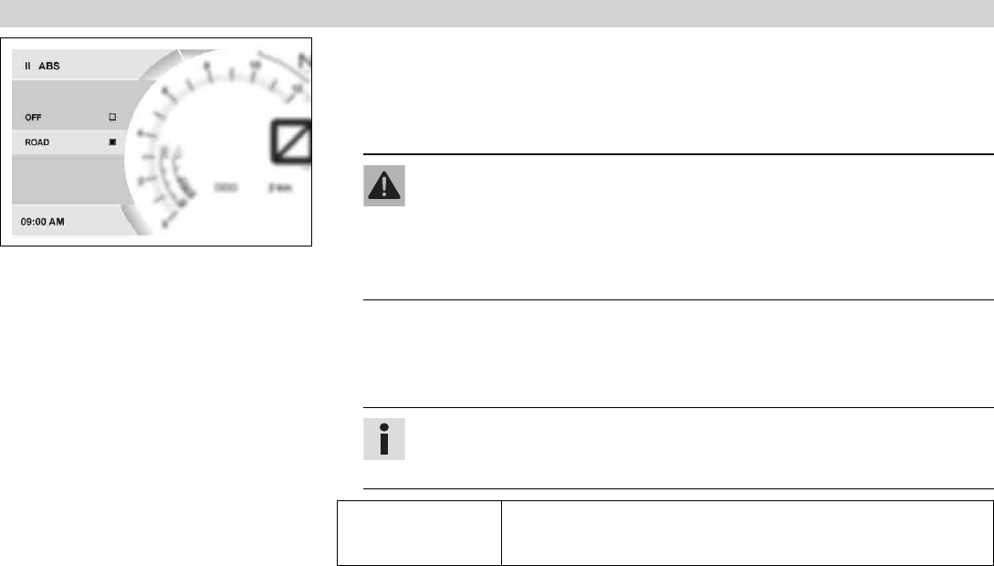
7.17.12 Warning
F00809-01
Condition
• Message or warning is present.
–Press the SET button when the menu is closed.
–Press the UP or DOWN button until Info is marked. Press the SET button to open the
menu.
–Press the UP or DOWN button until Warning is marked. Press the SET button to open the
menu.
–Use the UP or DOWN button to navigate through the warnings.
In the Warning menu, all warnings that have occurred are displayed and stored.
7 COMBINATION INSTRUMENT 56
7.17.13 ABS
F00811-02
Condition
• The motorcycle is stationary.
–Press the SET button when the menu is closed.
–Press the UP or DOWN button until Motorcycle is marked. Press the SET button to open
the menu.
Warning
Voiding of the government approval for road use and the insurance coverage If
the ABS is switched off completely, the vehicle's approval for road use is invali-
dated.
–Only operate the vehicle in closed-off areas remote from public road traffic if
the ABS is switched off completely.
–Press the UP or DOWN button until ABS is marked. Press the SET button to open the
menu.
–Activate the menu item using the UP or DOWN button.
–Switch off ABS by pressing the SET button.
Info
The ABS can only be reactivated by switching on the ignition again.
When the Road ABS mode is enabled, ABS controls both wheels.
Press and hold the
SET button for 3-5
seconds.
Switching off ABS.
7 COMBINATION INSTRUMENT 57
7.17.14 Favourites
F00814-01
Condition
• The motorcycle is stationary.
–Press the SET button when the menu is closed.
–Press the UP or DOWN button until Settings is marked. Press the SET button to open the
menu.
–Press the UP or DOWN button until Favourites is marked. Press the SET button to open
the menu.
–Press the UP or DOWN button to activate the menu item and select it with the SET but-
ton.
Up to eight items of information can be selected in the Favourites menu.
7.17.15 Quick Selector 1
F00815-01
Condition
• The motorcycle is stationary.
–Press the SET button when the menu is closed.
–Press the UP or DOWN button until Settings is marked. Press the SET button to open the
menu.
–Press the UP or DOWN button until Quick Selector 1 is marked. Press the SET button to
open the menu.
–Press the UP or DOWN button to activate the menu item and select it with the SET but-
ton.
Information can be selected in the Quick Selector 1 menu.
When the menu is closed, the Quick Selector 1 menu is opened by pressing the UP button.
7 COMBINATION INSTRUMENT 58
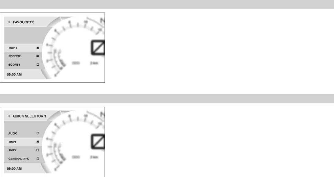
7.17.16 Quick Selector 2
F00816-01
Condition
• The motorcycle is stationary.
–Press the SET button when the menu is closed.
–Press the UP or DOWN button until Settings is marked. Press the SET button to open the
menu.
–Press the UP or DOWN button until Quick Selector 2 is marked. Press the SET button to
open the menu.
–Press the UP or DOWN button to activate the menu item and select it with the SET but-
ton.
Information can be selected in the Quick Selector 2 menu.
When the menu is closed, the Quick Selector 2 menu is opened by pressing the DOWN but-
ton.
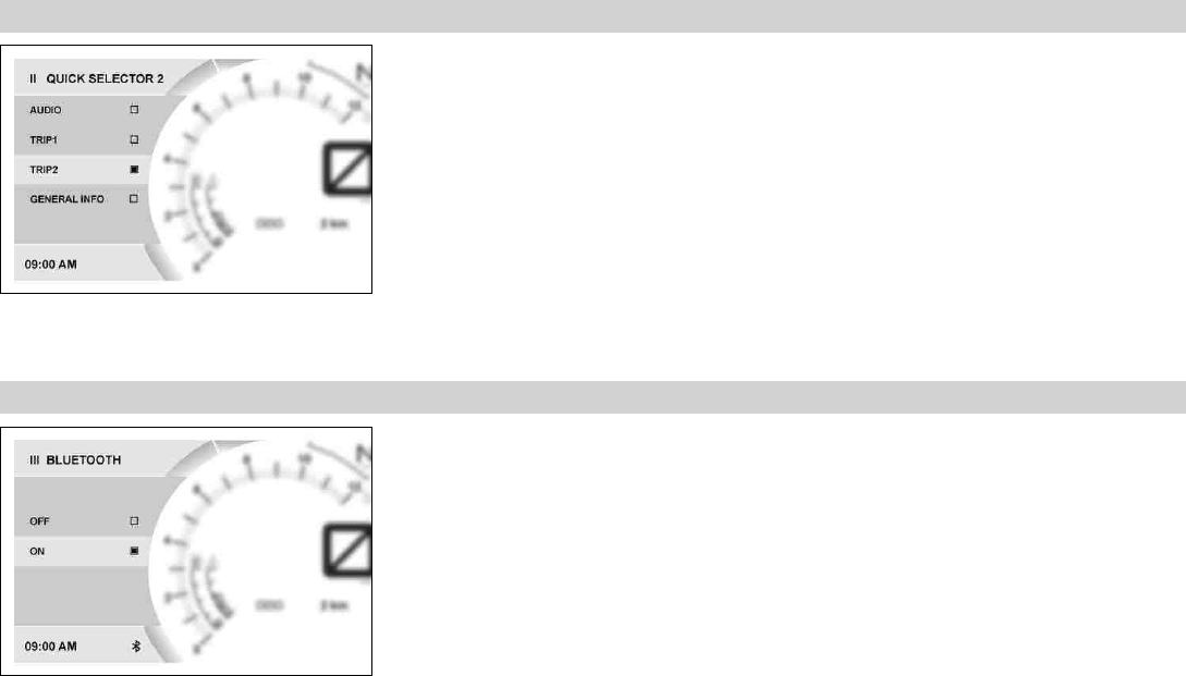
7.17.17 Bluetooth
F00818-01
Condition
• The motorcycle is stationary.
–Press the SET button when the menu is closed.
–Press the UP or DOWN button until Preferences is marked. Press the SET button to open
the menu.
–Press the UP or DOWN button until Bluetooth is marked. Press the SET button to open
the menu.
–Activate the menu item using the UP or DOWN button.
–Press the SET button to switch the Bluetooth®function on or off.
7 COMBINATION INSTRUMENT 59
Info
The Bluetooth®function can only be used in conjunction with KTM MY RIDE
(optional).
When the Bluetooth®function is switched on, the Bluetooth®symbol appears in the
display of the combination instrument.
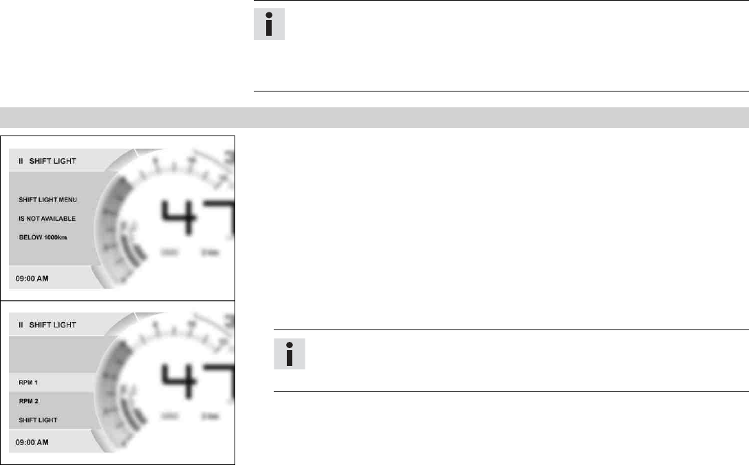
7.17.18 Shift Light
F00834-01
Condition
• The motorcycle is stationary.
•ODO > 1000 km (621 mi).
–Press the SET button when the menu is closed.
–Press the UP or DOWN button until Preferences is marked. Press the SET button to open
the menu.
–Press the UP or DOWN button until Shift Light is marked. Press the SET button to open
the menu.
–Activate the menu item using the UP or DOWN button.
–Press the SET button to switch the shift warning light on or off and to adjust the engine
speed for the gear shift recommendation.
Info
When the engine speed reaches RPM 1, the speed display lights up red.
When the engine speed reaches RPM 2, the speed display flashes red.
7 COMBINATION INSTRUMENT 60
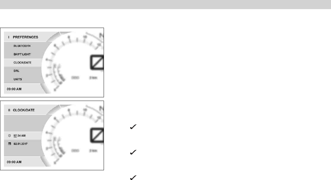
7.17.19 Setting the time and date
Condition
The motorcycle is stationary.
F00845-01
–Press the SET button when the menu is closed.
–Press the UP or DOWN button until Preferences appears. Press the SET button to open
the menu.
–Press the UP or DOWN button until Clock/Date is marked. Press the SET button to open
the menu.
F00843-01
Setting the clock
–Press the UP or DOWN button until the time is marked.
–Press the SET button.
The hour flashes and is underlined.
–Press the UP or DOWN button until the current hour is set.
–Press the SET button.
The minutes flash and are underlined.
–Press the UP or DOWN button until the current minute is set.
–Press the SET button.
The time is stored.
7 COMBINATION INSTRUMENT 61
F00844-01
Setting the date
–Press the UP or DOWN button until the date is marked.
–Press the SET button.
The day flashes and is underlined.
–Press the UP or DOWN button until the current day is set.
–Press the SET button.
The month flashes and is underlined.
–Press the UP or DOWN button until the current month is set.
–Press the SET button.
The year flashes and is underlined.
–Press the UP or DOWN button until the current year is set.
–Press the SET button.
The date is stored.
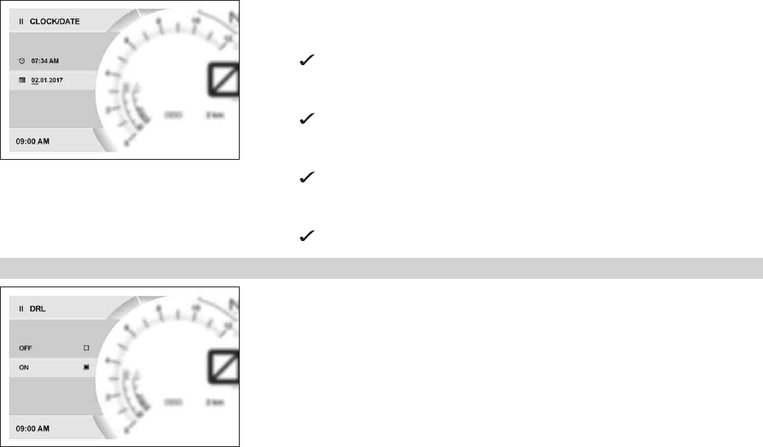
7.17.20 DRL
F00824-01
Condition
• The motorcycle is stationary.
–Press the SET button when the menu is closed.
–Press the UP or DOWN button until Preferences is marked. Press the SET button to open
the menu.
7 COMBINATION INSTRUMENT 62
Warning
Danger of accidents When visibility is poor, the daytime running light is not a
substitute for the low beam.
Automatic switching between the daytime running light and low beam may only
be partially available when visibility is significantly impaired due to fog, snow
or rain.
–Ensure that the appropriate type of lighting is always selected.
–If necessary switch off the daytime running lights using the menu before
going on a ride or when stopped so that the low beam is switched on per-
manently.
–Note the legal regulations regarding the daytime running light.
–Press the UP or DOWN button until DRL is marked. Press the SET button to open the
menu.
–Activate the menu item using the UP or DOWN button.
–Press the SET button to switch the daytime running light on or off.
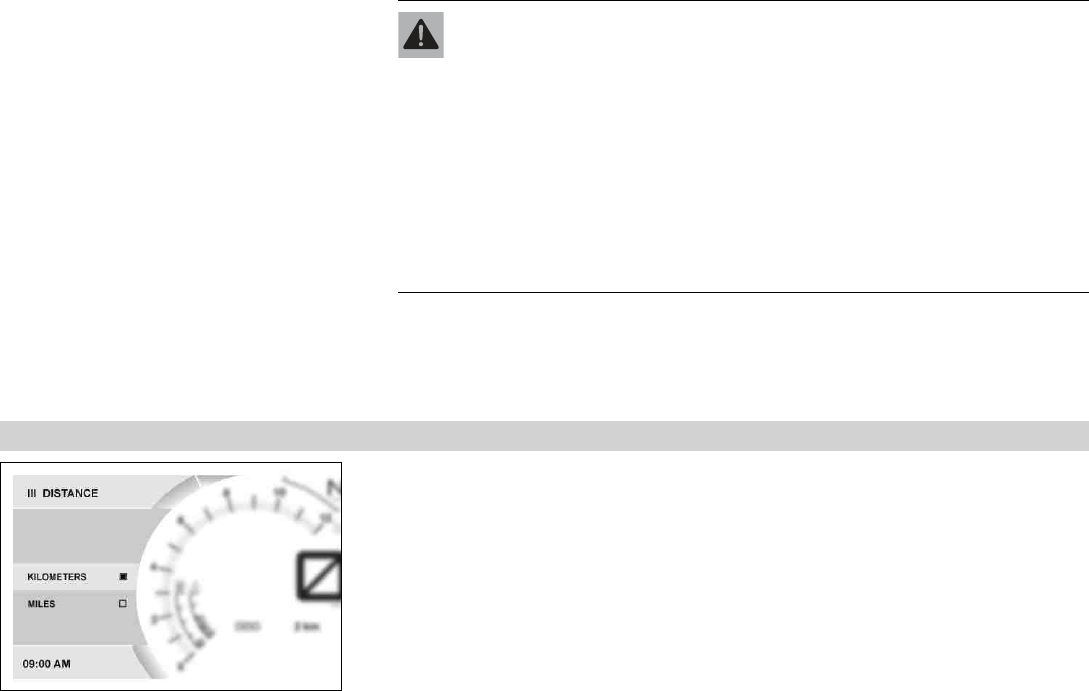
7.17.21 Distance
F00826-01
Condition
• The motorcycle is stationary.
–Press the SET button when the menu is closed.
–Press the UP or DOWN button until Preferences is marked. Press the SET button to open
the menu.
–Press the UP or DOWN button until Units is marked. Press the SET button to open the
menu.
–Press the UP or DOWN button until Distance is marked. Press the SET button to open the
menu.
7 COMBINATION INSTRUMENT 63
–Activate the menu item using the UP or DOWN button.
–Press the SET button to confirm the desired unit.
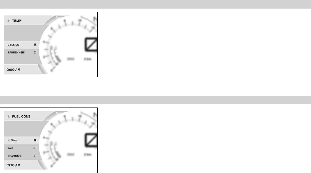
7.17.22 Temp
F00827-01
Condition
• The motorcycle is stationary.
–Press the SET button when the menu is closed.
–Press the UP or DOWN button until Preferences is marked. Press the SET button to open
the menu.
–Press the UP or DOWN button until Units is marked. Press the SET button to open the
menu.
–Press the UP or DOWN button until Temp is marked. Press the SET button to open the
menu.
–Activate the menu item using the UP or DOWN button.
–Press the SET button to confirm the desired unit.
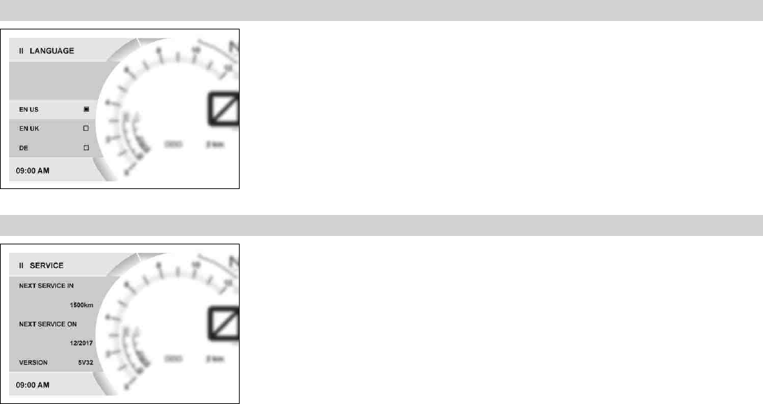
7.17.23 Fuel Cons
F00828-01
Condition
• The motorcycle is stationary.
–Press the SET button when the menu is closed.
–Press the UP or DOWN button until Preferences is marked. Press the SET button to open
the menu.
–Press the UP or DOWN button until Units is marked. Press the SET button to open the
menu.
–Press the UP or DOWN button until Fuel Cons is marked. Press the SET button to open
the menu.
–Activate the menu item using the UP or DOWN button.
7 COMBINATION INSTRUMENT 64
–Press the SET button to confirm the desired unit.
7.17.24 Language
F00829-01
Condition
• The motorcycle is stationary.
–Press the SET button when the menu is closed.
–Press the UP or DOWN button until Preferences is marked. Press the SET button to open
the menu.
–Press the UP or DOWN button until Language is marked. Press the SET button to open
the menu.
–Press the UP or DOWN button to activate the menu item and select it with the SET but-
ton.
The menu languages are US English, UK English, German, Italian, French, and Spanish.
7.17.25 Service
F00830-01
Condition
• The motorcycle is stationary.
–Press the SET button when the menu is closed.
–Press the UP or DOWN button until Preferences is marked. Press the SET button to open
the menu.
–Press the UP or DOWN button until Service is marked. Press the SET button to open the
menu.
The next service due is shown in the Service menu.
7 COMBINATION INSTRUMENT 65
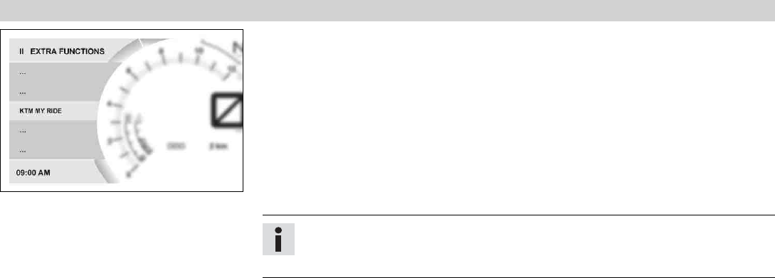
7.17.26 Extra Functions
F00831-01
Condition
• The motorcycle is stationary.
• Motorcycle with optional supplementary function.
–Press the SET button when the menu is closed.
–Press the UP or DOWN button until Preferences is marked. Press the SET button to open
the menu.
–Press the UP or DOWN button until Extra Functions is marked. Press the SET button to
open the menu.
–Use the UP or DOWN button to navigate through the extra functions.
The optional extra functions are listed in Extra Functions.
Info
The current KTM PowerParts and the available software for your vehicle can be found
on the KTM website.
8 PREPARING FOR USE 66
8.1 Advice on first use
Danger
Danger of accidents A rider who is not fit to ride poses a danger to him or herself and others.
–Do not operate the vehicle if you are not fit to ride due to alcohol, drugs or medication.
–Do not operate the vehicle if you are physically or mentally impaired.
Warning
Risk of injury Missing or poor protective clothing presents an increased safety risk.
–Wear appropriate protective clothing such as helmet, boots, gloves as well as trousers and a jacket with protectors on all rides.
–Always wear protective clothing that is in good condition and meets the legal regulations.
Warning
Danger of crashing Different tire tread patterns on the front and rear wheel impair the handling characteristic.
Different tire tread patterns can make the vehicle significantly more difficult to control.
–Make sure that only tires with a similar tire tread pattern are fitted to the front and rear wheel.
Warning
Danger of accidents Non-approved or non-recommended tires and wheels impact the handling characteristic.
–Only use tires/wheels approved by KTM with the corresponding speed index.
Warning
Danger of accidents New tires have reduced road grip.
The contact surface on new tires is not yet roughened.
–Run in new tires with moderate riding at alternating angles.
Running-in phase 200 km (124 mi)
8 PREPARING FOR USE 67
Info
When using your vehicle, remember that others may feel disturbed by excessive noise.
–Make sure that the pre-delivery inspection work has been carried out by an authorized KTM workshop.
You receive a delivery certificate and the Service and Warranty Booklet at vehicle handover.
–Before your first trip, read the entire operating instructions carefully.
–Get to know the controls.
–Get used to handling the motorcycle on a suitable piece of land before making a longer trip. Try also to ride as slowly as possible to get
a better feel for the vehicle.
–Hold the handlebar firmly with both hands and keep your feet on the footrests when riding.
–Run the engine in. ( p. 67)
8.2 Running in the engine
–During the running-in phase, do not exceed the specified engine speed.
Guideline
Maximum engine speed
During the first: 1,000 km (620 mi) 7,500 rpm
Info
During the running-in phase, the shift warning light is set to a specified value and cannot be changed.
–Avoid fully opening the throttle!
8 PREPARING FOR USE 68
8.3 Loading the vehicle
Warning
Danger of accidents Total weight and axle loads influence the handling characteristic.
The overall weight consists of: motorcycle ready for operation and with a full tank, driver and passenger with protective clothing
and helmet, and luggage.
–Do not exceed the maximum permissible overall weight or the axle loads.
Warning
Danger of accidents Improper mounting of cases or the tank rucksack impairs the handling characteristic.
–Mount and secure cases and tank rucksack according to the manufacturer's instructions.
Warning
Danger of accidents The luggage system will be damaged if it is overloaded.
–Read the manufacturer information on maximum payload when mounting cases.
Warning
Danger of accidents Luggage which has slipped impairs visibility.
If the tail light is covered, you are less visible to traffic behind you, especially when it is dark.
–Check that your luggage is fixed properly at regular intervals.
Warning
Danger of accidents A high payload alters the handling characteristic and increases the stopping distance.
–Adapt your speed to your payload.
Warning
Danger of accidents Pieces of luggage which have slipped impair the handling characteristic.
–Check that your luggage is fixed properly at regular intervals.

8 PREPARING FOR USE 69
–If you carry any baggage, make sure it is fixed firmly as close as possible to the center of the vehicle and ensure even weight distribu-
tion between the front and rear wheels.
–Do not exceed the overall maximum permitted weight and the axle loads.
Guideline
Maximum permissible overall weight 355 kg (783 lb.)
Maximum permissible front axle load 127 kg (280 lb.)
Maximum permissible rear axle load 228 kg (503 lb.)
9 RIDING INSTRUCTIONS 70
9.1 Checks and maintenance when preparing for use
Info
Before every trip, check the condition of the vehicle and ensure that it is roadworthy.
The vehicle must be in perfect technical condition when used.
–Check the engine oil level. ( p. 156)
–Check the brake fluid level of the front brake. ( p. 106)
–Check the rear brake fluid level. ( p. 112)
–Check the front brake linings. ( p. 109)
–Check the brake linings of the rear brake. ( p. 116)
–Check the brake system function.
–Check the coolant level. ( p. 146)
–Check for chain dirt accumulation. ( p. 94)
–Check the chain tension. ( p. 96)
–Check the tire condition. ( p. 125)
–Check the tire air pressure. ( p. 127)
–Check the settings of all controls and ensure that they can be operated smoothly.
–Check the functioning of the electrical equipment.
–Check that baggage is correctly secured.
–Sit on the motorcycle and check the rear mirror setting.
–Check the fuel level.
9 RIDING INSTRUCTIONS 71
9.2 Starting
Danger
Danger of poisoning Exhaust gases are toxic and inhaling them may result in unconsciousness and death.
–Always make sure there is sufficient ventilation when running the engine.
–Use an effective exhaust extraction system when starting or running the engine in an enclosed space.
Caution
Danger of accidents Electronic components and safety devices will be damaged if the battery is discharged or missing.
–Never operate the vehicle with a discharged battery or without a battery.
Note
Engine damage Unfiltered intake air has a negative effect on the service life of the engine.
Dust and dirt will enter the engine without an air filter.
–Never start to use the vehicle without an air filter.
Note
Engine damage High revving speed with a cold engine negatively impacts the lifespan of the engine.
–Always run the engine warm at a low speed.
9 RIDING INSTRUCTIONS 72
B00782-10
–Unlock the steering. ( p. 28)
–Sit on the vehicle, take the weight off of the side stand, and move up all the way.
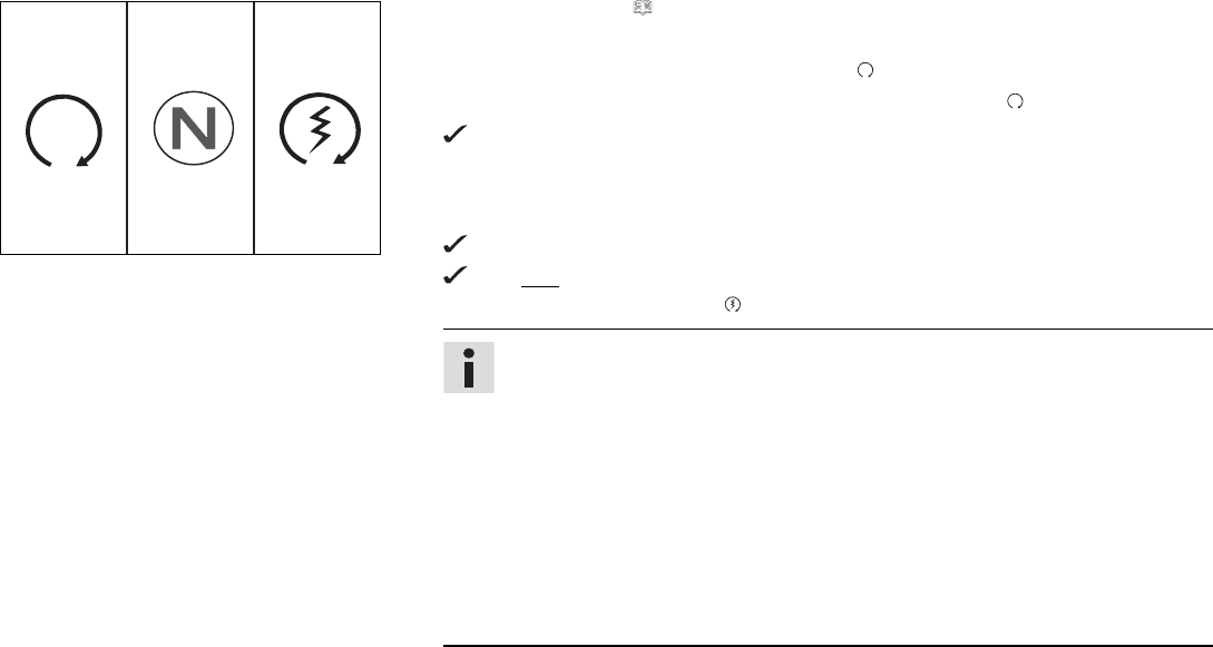
–Turn the emergency OFF switch to the position .
–Switch on the ignition by turning the ignition key to the position .
After you switch on the ignition, you can hear the fuel pump working for about two
seconds. The function check of the combination instrument is run at the same
time.
–Shift gear to neutral.
The green idle indicator lamp Nlights up.
The ABS indicator lamp lights up and goes back out after starting off.
–Press the electric starter button .
Info
Do not press the electric starter button until the combination instrument func-
tion check is finished.
When starting, DO NOT open the throttle. If you open the throttle during the start-
ing procedure, fuel is not injected by the engine management system and the
engine cannot start.
Press the starter for a maximum of 5 seconds. Wait for a least 5 seconds before
trying again.
This motorcycle is equipped with a safety starting system. You can only start
the engine if the transmission is in neutral or if the clutch lever is pulled when
a gear is engaged. If the side stand is folded out and you shift into gear and
release the clutch, the engine stops.
9 RIDING INSTRUCTIONS 73
9.3 Starting off
–Pull the clutch lever, engage 1st gear, release the clutch lever slowly, and simultaneously open the throttle carefully.
Tip
If the engine dies while starting off, only pull the clutch lever and press the electric starter button. You do not need to shift into
neutral.
9.4 Shifting, riding
Warning
Danger of accidents Abrupt load alterations can cause the vehicle to get out of control.
–Avoid abrupt load alterations and sudden braking actions.
–Adapt your speed to the road conditions.
Warning
Danger of accidents If you change down at high engine speed, the rear wheel blocks and the engine races.
–Do not change into a low gear at high engine speed.
Warning
Danger of accidents An incorrect ignition key position causes malfunctions.
–Do not change the ignition key position while driving.
Warning
Danger of accidents Adjustments to the vehicle distract attention from traffic activity.
–Make all adjustments when the vehicle is at a standstill.

9 RIDING INSTRUCTIONS 74
Warning
Risk of injury The passenger may fall from the motorcycle if they conduct themselves incorrectly.
–Ensure that the passenger sits correctly on the passenger seat, places his or her feet on the passenger foot rest and holds on to
the rider or the grab handles.
–Note the regulations governing the minimum age of passengers in your country.
Warning
Danger of accidents A risky riding style constitutes a major risk.
–Comply with traffic regulations and ride defensively and with foresight to detect sources of danger as early as possible.
Warning
Danger of accidents Cold tires have reduced road grip.
–Ride the first miles carefully on every journey at moderate speed until the tires reach operating temperature.
Warning
Danger of accidents New tires have reduced road grip.
The contact surface on new tires is not yet roughened.
–Run in new tires with moderate riding at alternating angles.
Running-in phase 200 km (124 mi)
Warning
Danger of accidents Pieces of luggage which have slipped impair the handling characteristic.
–Check that your luggage is fixed properly at regular intervals.
Warning
Danger of accidents A fall can damage the vehicle more seriously than it may first appear.
–Check the vehicle after a fall as you do when preparing for use.
9 RIDING INSTRUCTIONS 75
Note
Engine failure Overheating damages the engine.
–If the coolant temperature warning is displayed, stop immediately and take care not to endanger yourself or other traffic participants in
the process.
–Allow the engine and cooling system to cool down.
–Check and, if necessary, correct the coolant level on the cooling system while it is in a cooled state.
Info
If you hear unusual noises while riding, stop immediately, switch off the engine and contact an authorized KTM workshop.
401950-11
–Shift into a higher gear when conditions allow (incline, road situation, etc.).
–Release the throttle while simultaneously pulling the clutch lever, shift into the next
gear, release the clutch lever, and open the throttle.
Info
You can see the positions of the 6 forward gears in the figure. The idle position
is between the first and second gears. First gear is used for starting off or for
steep inclines.
–Accelerate only up to a speed suitable for the road surface and weather conditions. Par-
ticularly in bends, do not shift, and accelerate very carefully.
–Brake if necessary and close the throttle at the same time in order to shift down.
–Pull the clutch lever and shift into a lower gear, release the clutch lever slowly, and
open the throttle or shift again.
–Switch off the engine if running at idle or standing for a long time.
–If the malfunction indicator lamp lights up while riding, stop immediately taking care
not to endanger yourself or other road users in the process.
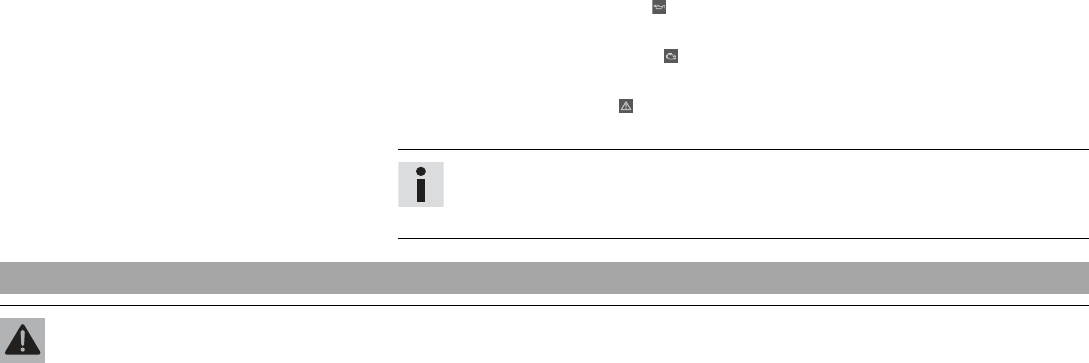
9 RIDING INSTRUCTIONS 76
–After reaching maximum speed by fully opening the throttle grip, turn the throttle back
so it is ¾ open. This will barely reduce the speed but fuel consumption will be consid-
erably lower.
–Accelerate only up to a speed suitable for the road surface and weather conditions. Par-
ticularly in bends, do not shift, and accelerate very carefully.
–Brake if necessary and close the throttle at the same time in order to shift down.
–Pull the clutch lever and shift into a lower gear, release the clutch lever slowly, and
open the throttle or shift again.
–If the engine stalls (e.g. at a crossroads), just pull the clutch lever and press the elec-
tric starter button. You do not have to shift into neutral.
–If the oil pressure warning lamp lights up during a trip, stop immediately and switch
off the engine. Contact an authorized KTM workshop.
–If the malfunction indicator lamp lights up during a trip, please contact an autho-
rized KTM workshop as soon as possible.
–If the general warning lamp lights up during a trip, an operating safety (warning)
message was detected.
Info
All warnings which have occurred are displayed and stored in the Warning menu
until these are no longer active.
9.5 Applying the brakes
Warning
Danger of accidents Moisture and dirt impair the brake system.
–Brake carefully several times to dry out and remove dirt from the brake linings and the brake discs.
9 RIDING INSTRUCTIONS 77
Warning
Danger of accidents A spongy pressure point on the front or rear brake reduces braking efficiency.
–Check the brake system and do not continue riding until the problem is eliminated. (Your authorized KTM workshop will be glad
to help.)
Warning
Danger of accidents The brake system fails in the event of overheating.
If the foot brake lever is not released, the brake linings drag continuously.
–Take your foot off the foot brake lever when you are not braking.
Warning
Danger of accidents Higher total weight increases the stopping distance.
–Take the longer stopping distance into account when carrying a passenger or luggage with you.
Warning
Danger of accidents Salt on the roads impairs the brake system.
–Brake carefully several times to remove salt from the brake linings and the brake discs.
Warning
Danger of accidents ABS may increase the stopping distance in certain situations.
–Adjust application of the brakes to the respective riding situation and riding surface conditions.
Warning
Danger of accidents Excessively forceful application of the brakes blocks the wheels.
The ABS effectiveness is only ensured if it is switched on.
–Leave the ABS switched on in order to benefit from the protective effect.
–When braking, release the throttle and apply the front and rear brakes at the same time.
9 RIDING INSTRUCTIONS 78
Info
When the ABS is enabled, you can achieve maximum braking power even on low grip surfaces such as sandy, wet, or slippery
terrain without locking of the wheels.
Warning
Danger of accidents The rear wheel can lock due to the engine braking effect.
–Pull in the clutch, if you perform emergency or full braking, or if you brake on a slippery ground.
Warning
Danger of accidents Banked or laterally sloping ground reduces the maximum possible delay.
–If possible finish braking before going into a bend.
–Always finish braking before you go into a bend. Change down to a lower gear appropriate to your road speed.
–Use the braking effect of the engine on long downhill stretches. Change down one or two gears, but do not over-rev the engine. In this
way, you have to brake far less and the brakes do not overheat.
9.6 Stopping, parking
Warning
Risk of injury People who act without authorization endanger themselves and others.
–Do not leave the vehicle unattended if the engine is running.
–Protect the vehicle against access by unauthorized persons.
–Lock the steering and remove the ignition key if you leave the vehicle unattended.
Warning
Danger of burns Some vehicle components become very hot when the vehicle is operated.
–Do not touch any parts such as the exhaust system, radiator, engine, shock absorber, or brake system before the vehicle parts
have cooled down.
–Let the vehicle parts cool down before you perform any work on the vehicle.

9 RIDING INSTRUCTIONS 79
Note
Material damage The vehicle may be damaged by incorrect procedure when parking.
Significant damage may be caused if the vehicle rolls away or falls over.
The components for parking the vehicle are designed only for the weight of the vehicle.
–Park the vehicle on a firm and level surface.
–Ensure that nobody sits on the vehicle when the vehicle is parked on a stand.
Note
Fire hazard Hot vehicle components pose a fire hazard and explosion risk.
–Do not park the vehicle near to materials which are highly flammable or explosive.
–Allow the vehicle to cool down before covering it.
–Apply the brakes on the motorcycle.
–Shift gear to neutral.
–Switch off the ignition by turning the ignition key to the position .
Info
If the engine is switched off with the emergency OFF switch and the ignition remains switched on at the ignition lock, power
continues to flow to most power consumers and the battery will discharge. You should therefore always switch off the engine
with the ignition key –the emergency OFF switch is intended for emergencies only.
–Park the motorcycle on a firm surface.
–Swing the side stand forward with your foot as far as it will go and lean the vehicle on it.
–Lock the steering. ( p. 27)
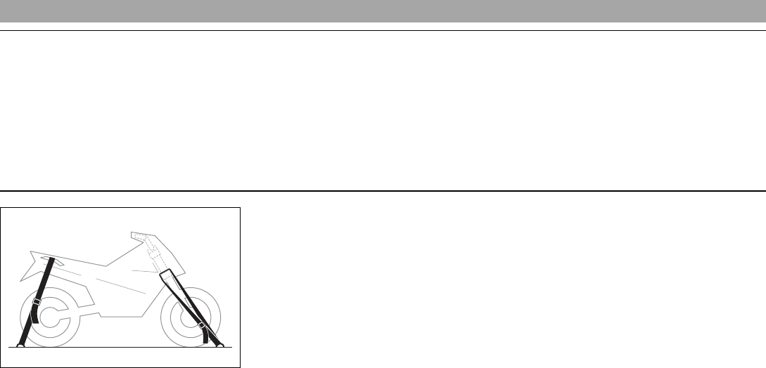
9 RIDING INSTRUCTIONS 80
9.7 Transport
Note
Danger of damage The parked vehicle can roll away or fall over.
–Park the vehicle on a firm and level surface.
Note
Fire hazard Hot vehicle components pose a fire hazard and explosion risk.
–Do not park the vehicle near to materials which are highly flammable or explosive.
–Allow the vehicle to cool down before covering it.
401448-01
–Switch off the engine and remove the ignition key.
–Use tension belts or other suitable devices to secure the motorcycle against accidents
or falling over.
9 RIDING INSTRUCTIONS 81
9.8 Refueling
Danger
Fire hazard Fuel is highly flammable.
The fuel in the fuel tank expands when warm and can escape if overfilled.
–Do not refuel the vehicle in the vicinity of open flames or lit cigarettes.
–Switch off the engine for refueling.
–Make sure that no fuel is spilled; particularly not on hot parts of the vehicle.
–If any fuel is spilled, wipe it off immediately.
–Observe the specifications for refueling.
Warning
Danger of poisoning Fuel is poisonous and a health hazard.
–Avoid skin, eye and clothing contact with fuel.
–Immediately consult a doctor if you swallow fuel.
–Do not inhale fuel vapors.
–In case of skin contact, rinse the affected area with plenty of water.
–Rinse the eyes thoroughly with water, and consult a doctor in case of fuel contact with the eyes.
–Change your clothing in case of fuel spills on them.
Note
Material damage Inadequate fuel quality causes the fuel filter to quickly become clogged.
In some countries and regions, the available fuel quality and cleanliness may not be sufficient. This will result in problems with the fuel
system.
–Refuel only with clean fuel that meets the specified standards. (Your authorized KTM workshop will be glad to help.)
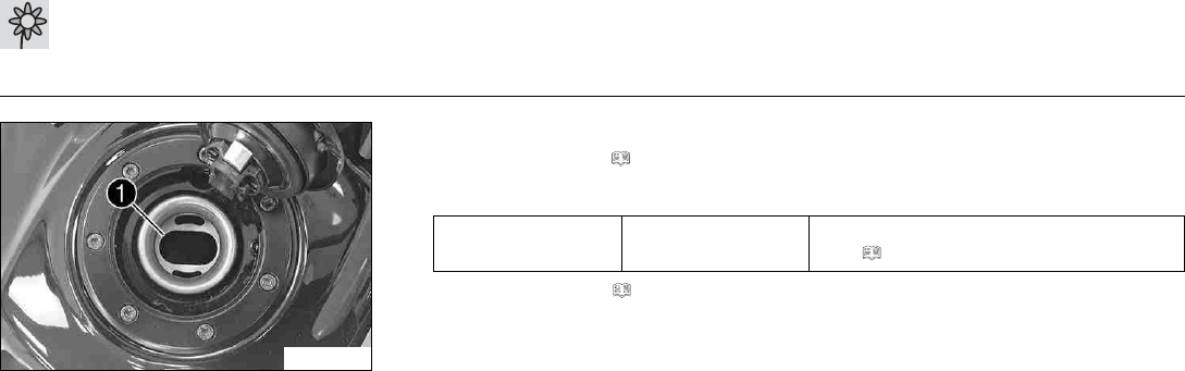
9 RIDING INSTRUCTIONS 82
Warning
Environmental hazard Improper handling of fuel is a danger to the environment.
–Do not allow fuel to enter the groundwater, the soil, or the sewage system.
F00732-10
–Switch off the engine.
–Open the filler cap. ( p. 28)
–Fill the fuel tank with fuel up to the lower edge 1of the fuel filler.
Total fuel tank
capacity, approx.
13.5 l
(3.57 US gal)
Super unleaded (ROZ 95/RON 95/PON
91) ( p. 187)
–Close the filler cap. ( p. 30)

10 SERVICE SCHEDULE 83
10.1 Additional information
Any further work that results from the required work or from the recommended work must be ordered separately and invoiced separately.
Different service intervals may apply in your country, depending on the local operating conditions.
10.2 Required work
Every two years
Every year
every 15,000 km (9,300 mi)
every 7,500 km (4,650 mi)
after 1,000 km (620 mi)
Read out the fault memory using the KTM diagnostics tool. ○ ● ● ● ●
Check that the electrical system is functioning properly. ○ ● ● ● ●
Change the engine oil and oil filter, clean the oil screen. ( p. 156) ○ ● ● ● ●
Check the brake discs. ( p. 105) ○ ● ● ● ●
Check the front brake linings. ( p. 109) ○ ● ● ● ●
Check the brake linings of the rear brake. ( p. 116) ○ ● ● ● ●
Check the brake lines for damage and leakage. ○ ● ● ● ●
Check the brake fluid level of the front brake. ( p. 106) ○ ● ● ●
Check the rear brake fluid level. ( p. 112) ○ ● ● ●
Check the tire condition. ( p. 125) ○ ● ● ● ●
Check the tire air pressure. ( p. 127) ○ ● ● ● ●
Check the shock absorber and fork for leaks. ○ ● ● ● ●
Clean the dust boots of the fork legs. ( p. 91) ● ●
Check the chain, rear sprocket, and engine sprocket. ( p. 99) ● ● ● ●
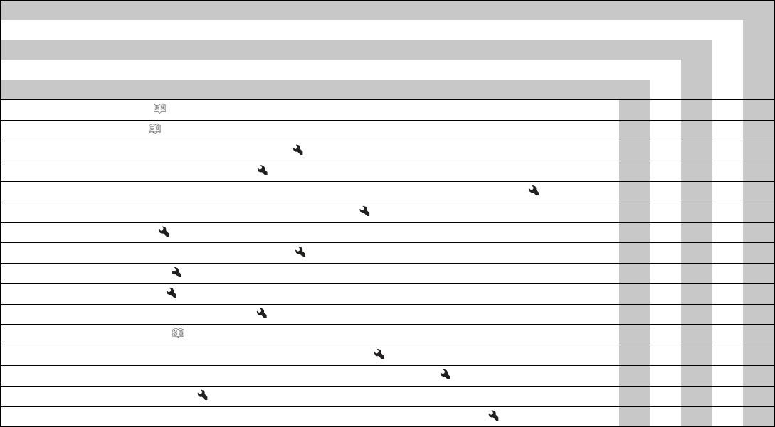
10 SERVICE SCHEDULE 84
Every two years
Every year
every 15,000 km (9,300 mi)
every 7,500 km (4,650 mi)
after 1,000 km (620 mi)
Check the chain tension. ( p. 96) ○ ● ● ● ●
Check the coolant level. ( p. 146) ○ ● ● ● ●
Check that the radiator fan is functioning properly. ○ ● ● ● ●
Change the air filter. Clean the air filter box. ● ●
Check that the throttle cables are undamaged, routed without sharp bends, and set correctly. ○ ● ● ● ●
Check the cables for damage and routing without sharp bends. ○ ● ● ● ●
Check the valve clearance. ○
Check the valve clearance, change the spark plugs. ●
Change the front brake fluid. ●
Change the rear brake fluid. ●
Check the play of the steering head bearing. ○ ● ● ● ●
Check the headlight setting. ( p. 139) ○ ● ●
Final check: Check the vehicle is roadworthy and take a test ride. ○ ● ● ● ●
Read out the error memory after the test ride using the KTM diagnostics tool. ○ ● ● ● ●
Reset the service interval display. ○ ● ● ● ●
Make the service entry in the KTM Dealer.net and in the Service and Warranty Booklet. ○ ● ● ● ●
○One-time interval
●Periodic interval
10 SERVICE SCHEDULE 85
10.3 Recommended work
Every four years
Every year
every 30,000 km (18,600 mi)
every 7,500 km (4,650 mi)
after 1,000 km (620 mi)
Check the frame. ●
Check the swingarm. ●
Check the swingarm bearing. ● ●
Check the wheel bearings. ● ●
Check the antifreeze. ○ ● ● ●
Change the coolant. ●
Empty the drainage hoses. ○ ● ● ● ●
Check all hoses (e.g. fuel, coolant, bleeder, drainage, etc.) and sleeves for cracking, leaks, and incorrect
routing.
○ ● ● ● ●
Grease all moving parts (e.g., side stand, hand lever, chain, ...) and check for smooth operation. ○ ● ● ● ●
Check the screws and nuts for tightness. ○ ● ● ● ●
○One-time interval
●Periodic interval
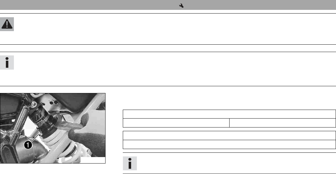
11 TUNING THE CHASSIS 86
11.1 Adjusting the spring pretension of the shock absorber
Warning
Danger of accidents Modifications to the suspension settings can seriously alter the vehicle's ride behavior.
–Following modifications, ride slowly at first to get the feel of the new ride behavior.
Info
The spring pretension defines the initial status of the spring operation on the shock absorber.
The best spring pretension setting is achieved when it is set for the weight of the rider and that of any baggage and a passenger,
thus ensuring an ideal compromise between maneuverability and stability.
F00779-10
–Adjust the spring pretension by turning adjusting ring 1.
Guideline
Spring preload
Standard 3 clicks
Hook wrench, shock absorber (90529077000)
Extension for hook wrench (90129099025)
Info
The spring pretension can be set to 10 different positions.
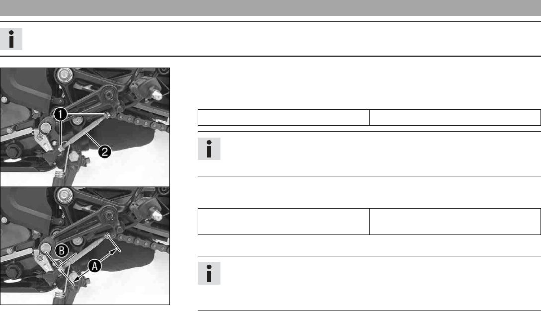
11 TUNING THE CHASSIS 87
11.2 Adjusting the shift lever
Info
The adjustment range of the shift lever is limited.
F00734-10
–Loosen nuts 1.
–Adjust the shift lever by turning shift rod 2.
Guideline
Shift rod adjustment range A90… 102 mm (3.54… 4.02 in)
Info
Make the same adjustments on both sides.
At least five screw threads must be screwed into the seating.
–Check adjusting angle B.
Guideline
Adjusting angle Bshift rod - bell crank
- shift lever
90°
–Tighten nuts 1.
Info
After the nuts have been tightened, the bearings of the shift rod must be central
and aligned identically to each other in order to ensure freedom of movement in
the bearing shells.
–Check the shift lever to ensure it is functioning properly and can move freely.
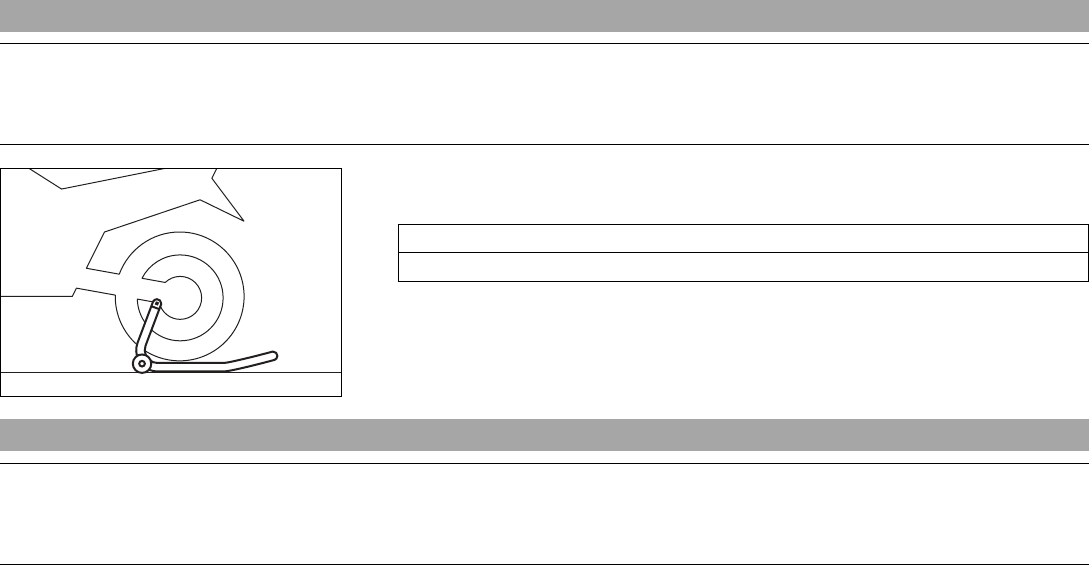
12 SERVICE WORK ON THE CHASSIS 88
12.1 Raising the motorcycle with the rear lifting gear
Note
Danger of damage The parked vehicle can roll away or fall over.
–Park the vehicle on a firm and level surface.
402346-01
–Mount the supports of the lifting gear.
–Insert the adapter in the rear lifting gear.
Retaining adapter (61029955244)
Lifting gear, rear (69329955000)
–Stand the motorcycle upright, align the lifting gear with the swingarm and the adapters,
and lift the motorcycle.
12.2 Removing the rear of the motorcycle from the lifting gear
Note
Danger of damage The parked vehicle can roll away or fall over.
–Park the vehicle on a firm and level surface.
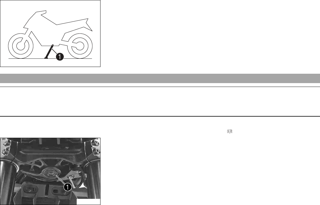
12 SERVICE WORK ON THE CHASSIS 89
402029-10
–Secure the motorcycle against falling over.
–Remove the rear lifting gear and lean the vehicle on side stand 1.
–Remove bushings kit.
12.3 Lifting the motorcycle with the front lifting gear
Note
Danger of damage The parked vehicle can roll away or fall over.
–Park the vehicle on a firm and level surface.
Preparatory work
–Raise the motorcycle with the rear lifting gear. ( p. 88)
F00735-10
Condition
–Remove protection cap 1.
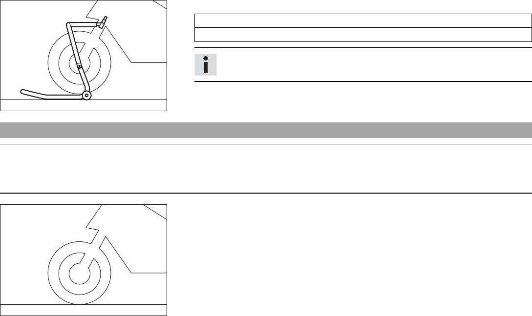
12 SERVICE WORK ON THE CHASSIS 90
402345-01
–Move the handlebar to the straight-ahead position. Position the lifting gear.
Mounting pin (69329965030)
Lifting gear, front (69329965000)
Info
Always raise the motorcycle at the rear first.
–Raise the motorcycle at the front.
12.4 Taking the motorcycle from the front lifting gear
Note
Danger of damage The parked vehicle can roll away or fall over.
–Park the vehicle on a firm and level surface.
402777-01
Main work
–Secure the motorcycle against falling over.
–Remove the front lifting gear.
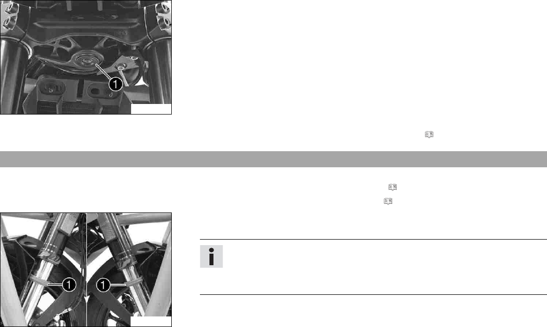
12 SERVICE WORK ON THE CHASSIS 91
F00735-10
–Mount protection cap 1.
Finishing work
–Remove the rear of the motorcycle from the lifting gear. ( p. 88)
12.5 Cleaning the dust boots of the fork legs
Preparatory work
–Raise the motorcycle with the rear lifting gear. ( p. 88)
–Lift the motorcycle with the front lifting gear. ( p. 89)
E00735-10
Main work
–Push dust boots 1of both fork legs downward.
Info
The dust boots should remove dust and coarse dirt particles from the fork
tubes. Over time, dirt can accumulate behind the dust boots. If this dirt is not
removed, the oil seals behind can start to leak.
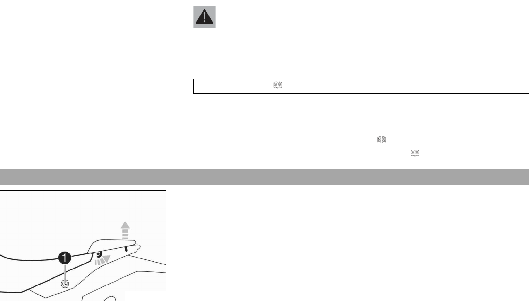
12 SERVICE WORK ON THE CHASSIS 92
Warning
Danger of accidents Oil or grease on the brake discs reduces the braking effect.
–Always keep the brake discs free of oil and grease.
–Clean the brake discs with brake cleaner when necessary.
–Clean and oil the dust boots and inner fork tubes of both fork legs.
Universal oil spray ( p. 189)
–Press the dust boots back into their installation position.
–Remove excess oil.
Finishing work
–Take the motorcycle from the front lifting gear. ( p. 90)
–Remove the rear of the motorcycle from the lifting gear. ( p. 88)
12.6 Removing the passenger seat
H01991-10
–Insert the ignition key in seat lock 1and turn it clockwise.
–Raise the rear of the seat, push it towards the rear, and remove it upwards.
–Remove the ignition key from the seat lock.
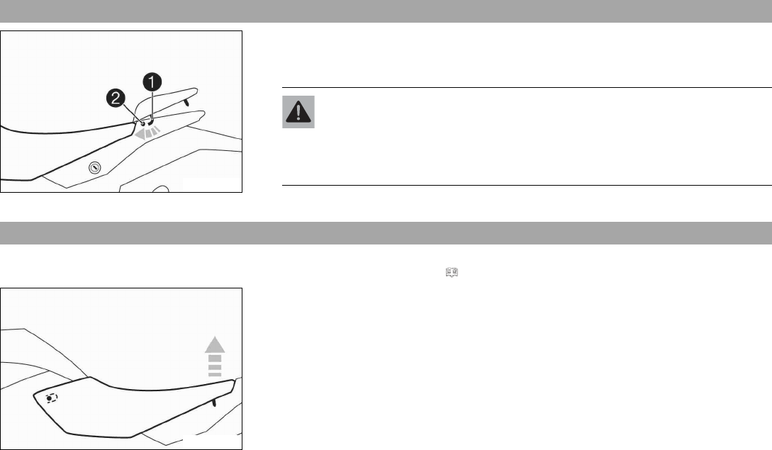
12 SERVICE WORK ON THE CHASSIS 93
12.7 Mounting the passenger seat
H01992-01
–Attach hooks 1on the passenger seat to seat mounting 2on the subframe, and
lower it at the rear while pushing forward.
–Press down the passenger seat until it clicks into place.
Warning
Danger of accidents The passenger seat can come loose from the anchoring if it
is not mounted correctly.
–After mounting the passenger seat, check that it is locked correctly by
pulling up.
–Finally, check that the passenger seat is correctly mounted.
12.8 Removing the front rider's seat
Preparatory work
–Remove the passenger seat. ( p. 92)
H01993-01
Main work
–Raise the rear of the front rider's seat, pull it towards the rear, and remove it upwards.
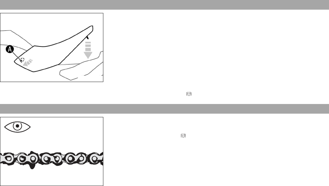
12 SERVICE WORK ON THE CHASSIS 94
12.9 Mounting the front rider's seat
H01994-01
Main work
–Attach the front rider's seat in area Aand lower at the rear.
–Finally, check that the driver's seat is correctly mounted.
Finishing work
–Mount the passenger seat. ( p. 93)
12.10 Checking for chain dirt accumulation
400678-01
–Check the chain for coarse dirt accumulation.
» If the chain is very dirty:
–Clean the chain. ( p. 95)
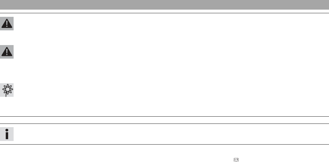
12 SERVICE WORK ON THE CHASSIS 95
12.11 Cleaning the chain
Warning
Danger of accidents Oil or grease on the tires reduces the road grip.
–Remove the lubricant from the tires using a suitable cleaning agent.
Warning
Danger of accidents Oil or grease on the brake discs reduces the braking effect.
–Always keep the brake discs free of oil and grease.
–Clean the brake discs with brake cleaner when necessary.
Warning
Environmental hazard Hazardous substances cause environmental damage.
–Dispose of oils, grease, filters, fuel, cleaning agents, brake fluid, etc., correctly and in compliance with the applicable regula-
tions.
Info
The service life of the chain depends largely on its maintenance.
Preparatory work
–Raise the motorcycle with the rear lifting gear. ( p. 88)
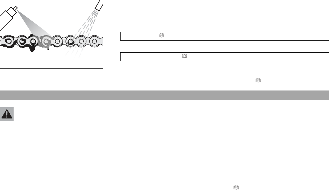
12 SERVICE WORK ON THE CHASSIS 96
400725-01
Main work
–Clean the chain regularly.
–Rinse off loose dirt with a soft jet of water.
–Remove old grease remains with chain cleaner.
Chain cleaner ( p. 188)
–After drying, apply chain spray.
Chain lube for road use ( p. 188)
Finishing work
–Remove the rear of the motorcycle from the lifting gear. ( p. 88)
12.12 Checking the chain tension
Warning
Danger of accidents Incorrect chain tension damages components and results in accidents.
If the chain is tensioned too much, the chain, engine sprocket, rear sprocket, transmission and rear wheel bearings wear more
quickly. Some components may break if overloaded.
If the chain is too loose, the chain may fall off the engine sprocket or the rear sprocket. As a result, the rear wheel locks or the
engine will be damaged.
–Check the chain tension regularly.
–Set the chain tension in accordance with the specification.
Preparatory work
–Raise the motorcycle with the rear lifting gear. ( p. 88)
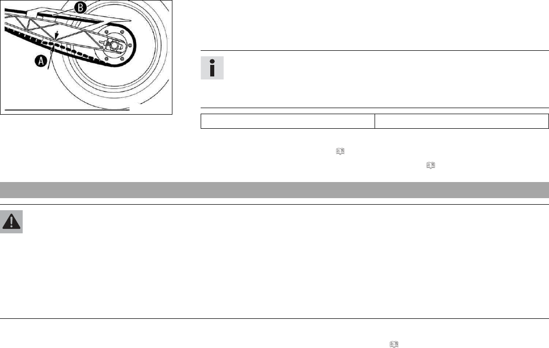
12 SERVICE WORK ON THE CHASSIS 97
M00714-10
Main work
–Shift gear to neutral.
–In the area of the chain sliding guard, press the chain upward toward the swingarm and
determine chain tension A.
Info
The upper part of chain Bmust be taut.
Chain wear is not always even, so you should repeat this measurement at differ-
ent chain positions.
Chain tension 5… 7 mm (0.2… 0.28 in)
» If the chain tension does not meet the specification:
–Adjust the chain tension. ( p. 97)
–Remove the rear of the motorcycle from the lifting gear. ( p. 88)
12.13 Adjusting the chain tension
Warning
Danger of accidents Incorrect chain tension damages components and results in accidents.
If the chain is tensioned too much, the chain, engine sprocket, rear sprocket, transmission and rear wheel bearings wear more
quickly. Some components may break if overloaded.
If the chain is too loose, the chain may fall off the engine sprocket or the rear sprocket. As a result, the rear wheel locks or the
engine will be damaged.
–Check the chain tension regularly.
–Set the chain tension in accordance with the specification.
Preparatory work
–Raise the motorcycle with the rear lifting gear. ( p. 88)
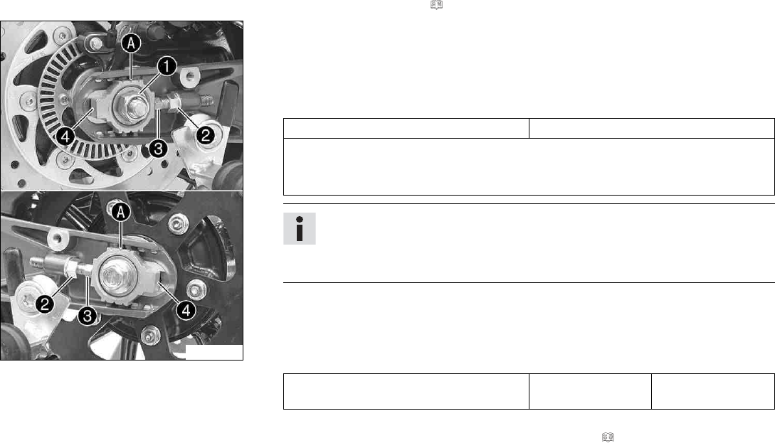
12 SERVICE WORK ON THE CHASSIS 98
–Check the chain tension. ( p. 96)
F00745-10
Main work
–Loosen nut 1.
–Loosen nuts 2.
–Adjust the chain tension by turning adjusting screws 3left and right.
Guideline
Chain tension 5… 7 mm (0.2… 0.28 in)
Turn the adjusting screws 3on the left and right so that the markings on the
left and right chain adjusters 4are in the same position relative to the reference
marks A. The rear wheel is then correctly aligned.
Info
The upper part of the chain must be taut.
Chain wear is not always even, so you should check the setting at different chain
positions.
–Tighten nuts 2.
–Make sure that chain adjusters 4are fitted correctly on adjusting screws 3.
–Tighten nut 1.
Guideline
Nut, rear wheel spindle M14x1.5 98 Nm
(72.3 lbf ft)
Finishing work
–Remove the rear of the motorcycle from the lifting gear. ( p. 88)
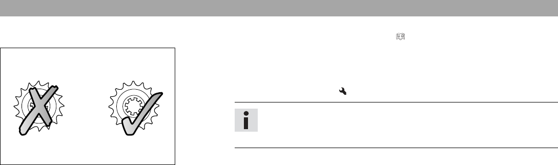
12 SERVICE WORK ON THE CHASSIS 99
12.14 Checking the chain, rear sprocket, and engine sprocket
Preparatory work
–Raise the motorcycle with the rear lifting gear. ( p. 88)
100132-10
Main work
–Check the rear sprocket and engine sprocket for wear.
» If the rear sprocket and engine sprocket are worn:
–Change the drivetrain kit.
Info
The engine sprocket, rear sprocket and chain should always be replaced
together.
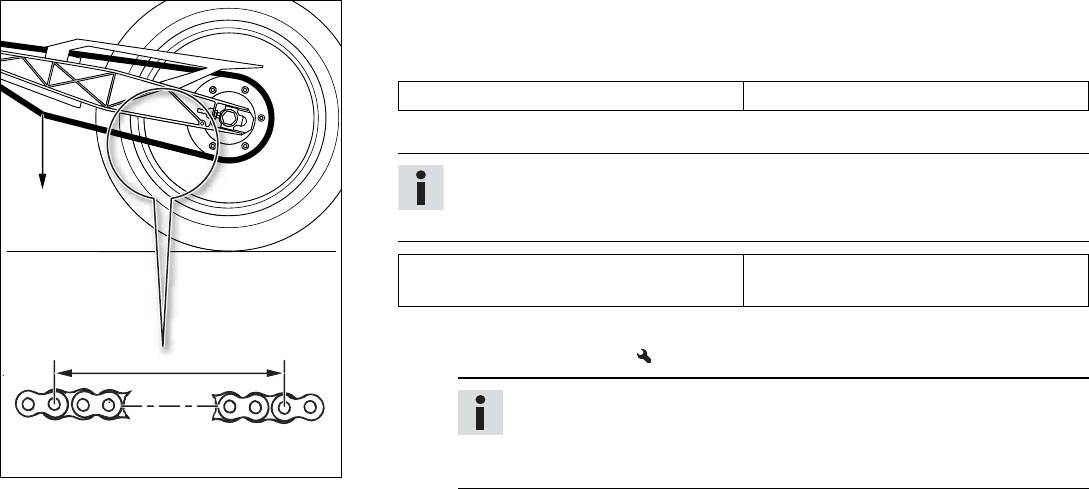
12 SERVICE WORK ON THE CHASSIS 100
1 2 3 18 19 20
00
0
BB
0
0
AA
401288-10
–Shift gear to neutral.
–Pull the lower chain section with specified weight A.
Guideline
Weight, chain wear measurement 15 kg (33 lb.)
–Measure distance Bof 20 chain rollers in the lower chain section.
Info
Chain wear is not always even, so you should repeat this measurement at differ-
ent chain positions.
Maximum distance Bat the longest
chain section
301.6 mm (11.874 in)
»If distance Bis greater than the specified measurement:
–Change the power set.
Info
When a new chain is mounted, the rear sprocket and engine sprocket
should also be changed.
New chains wear out faster on old, worn sprockets.
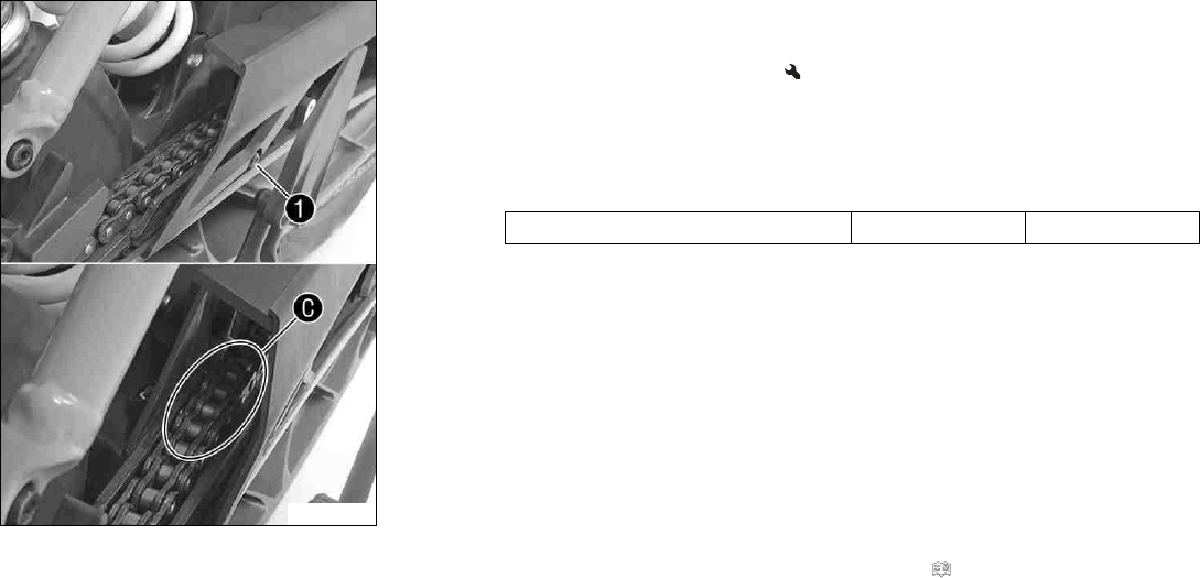
12 SERVICE WORK ON THE CHASSIS 101
F00752-10
–Check the chain sliding guard for wear.
»If in area Cby the chain sliding guard screw 1is visible from above:
–Change the chain sliding guard.
–Check that the chain sliding guard is firmly seated.
» If the chain sliding guard is loose:
–Tighten the screw of the chain sliding guard.
Guideline
Screw, chain sliding guard M6 7 Nm (5.2 lbf ft)
Finishing work
–Remove the rear of the motorcycle from the lifting gear. ( p. 88)
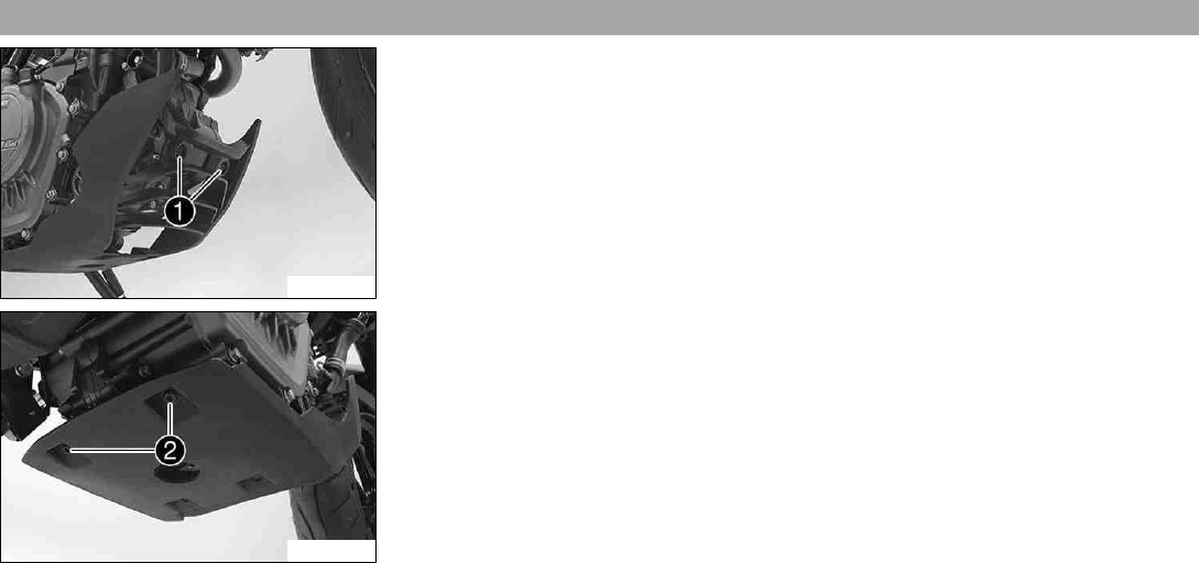
12 SERVICE WORK ON THE CHASSIS 102
12.15 Removing the front spoiler
F00740-10
–Remove screws 1.
F00739-10
–Remove screws 2.
–Take off the front spoiler.

12 SERVICE WORK ON THE CHASSIS 103
12.16 Fitting front spoiler
F00740-10
–Position the front spoiler. Mount screws 1but do not tighten yet.
F00739-10
–Mount and tighten screws 2.
Guideline
Screw, front spoiler rear M6x9 9 Nm (6.6 lbf ft)
–Tighten screws 1.
Guideline
Screw, front spoiler front M6x13 9 Nm (6.6 lbf ft)
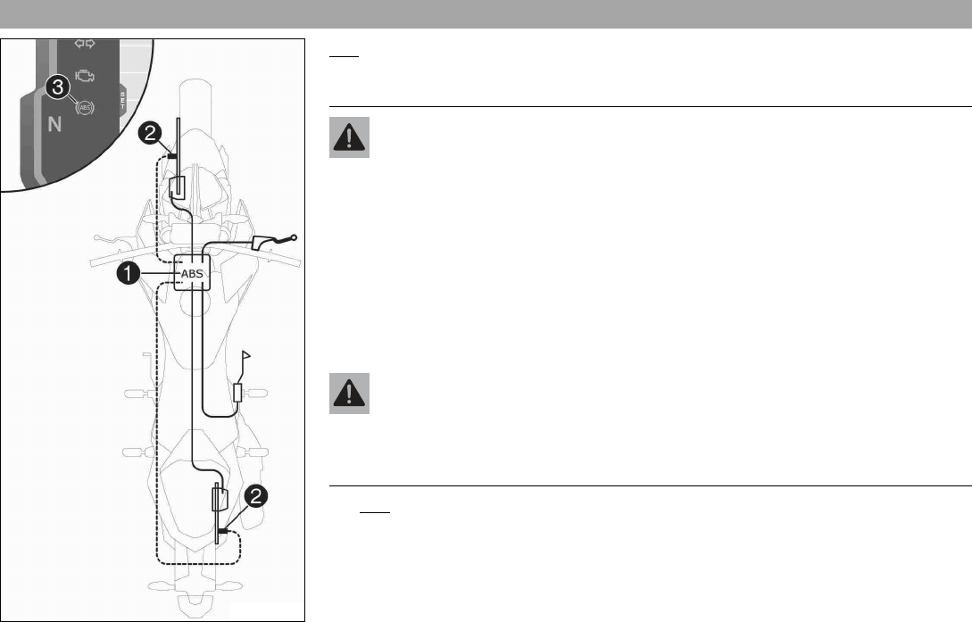
13 BRAKE SYSTEM 104
13.1 Antilock braking system (ABS)
H01908-10
ABS unit 1, which consists of a hydraulic unit, ABS control unit, and return pump, is
installed under the fuel tank. One wheel speed sensor 2is located in each case on the
front and the rear wheel.
Warning
Danger of accidents Changes to the vehicle impair the function of the ABS.
–Only allow the rear wheel to spin with the front brake applied away from public
road traffic if the ABS is switched off.
–Do not make any changes to the suspension travel.
–Only use spare parts on the brake system which have been approved and recom-
mended by KTM.
–Only use tires/wheels approved by KTM with the corresponding speed index.
–Maintain the specified tire air pressure.
–Service work and repairs must be performed professionally. (Your authorized
KTM workshop will be glad to help.)
Warning
Voiding of the government approval for road use and the insurance coverage If the
ABS is switched off completely, the vehicle's approval for road use is invalidated.
–Only operate the vehicle in closed-off areas remote from public road traffic if the
ABS is switched off completely.
The ABS is a safety system that prevents locking of the wheels when driving straight ahead
without the influence of lateral forces.
13 BRAKE SYSTEM 105
Warning
Danger of accidents Driving aids can only prevent a rollover within the physical limi-
tations.
It is not always possible to compensate for extreme riding situations, for exam-
ple with luggage loaded with a high center of gravity, varying road surfaces, steep
descents or full braking without disengaging the gear.
–Adapt your riding style to the road conditions and your driving ability.
The ABS operates with two independent brake circuits (front and rear brakes). During nor-
mal operation, the brake system operates like a conventional brake system without ABS.
When the ABS control unit detects a locking tendency in a wheel, ABS begins regulating
the brake pressure. The regulating process causes a slight pulsing of the hand and foot
brake levers.
The ABS indicator lamp 3must light up after the ignition is switched on and go out after
starting off. If it does not go out after starting off or if it lights up while riding, this indi-
cates a fault in the ABS system. In this case, the ABS is no longer enabled and the wheels
may lock during braking. The brake system itself stays functional; only ABS control is not
available.
The ABS indicator lamp may also light up if the rotating speeds of the front and rear wheels
differ greatly under extreme riding conditions, for example when making "wheelies" or if the
rear wheel spins. This causes the ABS to switch off.
To reactivate the ABS, the vehicle must be stopped and the ignition switched off. The ABS
is reactivated when the vehicle is switched on again. The ABS indicator lamp goes out
when you start off.
13.2 Checking the brake discs
Warning
Danger of accidents Worn-out brake discs reduce the braking effect.
–Make sure that worn-out brake discs are replaced immediately. (Your authorized KTM workshop will be glad to help.)
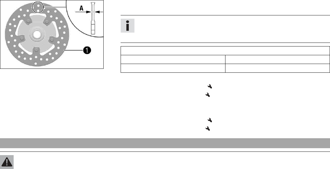
13 BRAKE SYSTEM 106
400480-10
–Check the thickness of the front and rear brake discs at multiple points on each brake
disc to ensure it is at least thickness A.
Info
Wear will reduce the thickness of the brake disc at contact surface 1of the
brake linings.
Brake discs - wear limit
Front 4.5 mm (0.177 in)
rear 3.6 mm (0.142 in)
» If the brake disc thickness is less than the specified value.
–Change the front brake disc.
–Change the rear brake disc.
–Check the front and rear brake discs for damage, cracking, and deformation.
» If the brake disc exhibits damage, cracking, or deformation:
–Change the front brake disc.
–Change the rear brake disc.
13.3 Checking the brake fluid level of the front brake
Warning
Danger of accidents An insufficient brake fluid level will cause the brake system to fail.
If the brake fluid level drops below the MIN marking, the brake system is leaking or the brake linings are worn down.
–Check the brake system and do not continue riding until the problem is eliminated. (Your authorized KTM workshop will be glad
to help.)
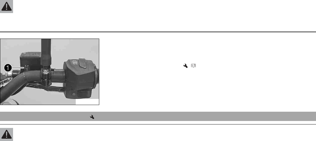
13 BRAKE SYSTEM 107
Warning
Danger of accidents Old brake fluid reduces the braking effect.
–Make sure that brake fluid for the front and rear brake is changed in accordance with the service schedule. (Your authorized
KTM workshop will be glad to help.)
F00746-10
–Move the brake fluid reservoir mounted on the handlebar to a horizontal position.
–Check the brake fluid level in viewer 1.
» If the brake fluid level is below the MINmarking:
–Add front brake fluid. ( p. 107)
13.4 Adding front brake fluid
Warning
Danger of accidents An insufficient brake fluid level will cause the brake system to fail.
If the brake fluid level drops below the MIN marking, the brake system is leaking or the brake linings are worn down.
–Check the brake system and do not continue riding until the problem is eliminated. (Your authorized KTM workshop will be glad
to help.)
13 BRAKE SYSTEM 108
Warning
Skin irritation Brake fluid causes skin irritation.
–Keep brake fluid out of the reach of children.
–Wear suitable protective clothing and safety glasses.
–Do not allow brake fluid to come into contact with the skin, the eyes or clothing.
–Consult a doctor immediately if brake fluid has been swallowed.
–Rinse the affected area with plenty of water in the event of contact with the skin.
–Rinse eyes thoroughly with water immediately and consult a doctor if brake fluid comes into contact with the eyes.
–If brake fluid spills on to your clothing, change the clothing.
Warning
Danger of accidents Old brake fluid reduces the braking effect.
–Make sure that brake fluid for the front and rear brake is changed in accordance with the service schedule. (Your authorized
KTM workshop will be glad to help.)
Warning
Environmental hazard Hazardous substances cause environmental damage.
–Dispose of oils, grease, filters, fuel, cleaning agents, brake fluid, etc., correctly and in compliance with the applicable regula-
tions.
Info
Never use DOT 5 brake fluid. It is silicone-based and purple in color. Oil seals and brake lines are not designed for DOT 5 brake
fluid.
Avoid contact between brake fluid and painted parts. Brake fluid attacks paint.
Only use clean brake fluid from a sealed container.
Preparatory work
–Check the front brake linings. ( p. 109)
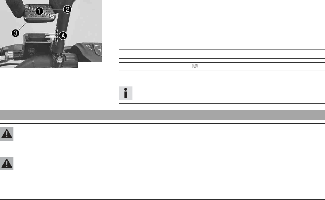
13 BRAKE SYSTEM 109
F00747-10
Main work
–Move the brake fluid reservoir mounted on the handlebar to a horizontal position.
–Remove screws 1.
–Remove cover 2with membrane 3.
–Add brake fluid to level A.
Guideline
Level A5 mm (0.2 in)
Brake fluid DOT 4 / DOT 5.1 ( p. 185)
–Position the cover with the membrane. Mount and tighten the screws.
Info
Clean up overflowed or spilled brake fluid immediately with water.
13.5 Checking the front brake linings
Warning
Danger of accidents Worn-out brake linings reduce the braking effect.
–Ensure that worn-out brake linings are replaced immediately. (Your authorized KTM workshop will be glad to help.)
Warning
Danger of accidents Damaged brake discs reduce the braking effect.
If the brake linings are not changed in time, the brake lining carriers grind against the brake disc. As a consequence, the braking
effect is greatly reduced and the brake discs are destroyed.
–Check the brake linings regularly.
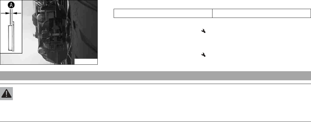
13 BRAKE SYSTEM 110
F00748-10
–Check the brake linings for minimum thickness A.
Minimum thickness A≥1 mm (≥0.04 in)
» If the minimum thickness is less than specified:
–Change the front brake linings.
–Check the brake linings for damage and cracking.
» If there is damage or cracking:
–Change the front brake linings.
13.6 Checking the free travel of foot brake lever
Warning
Danger of accidents The brake system fails in the event of overheating.
If there is no free travel on the foot brake lever, pressure builds up in the brake system on the rear brake.
–Set the free travel on the foot brake lever in accordance with the specification.
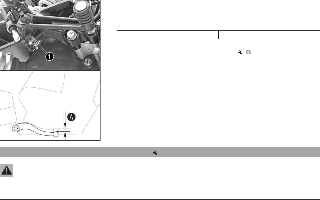
13 BRAKE SYSTEM 111
F00751-10
–Disconnect spring 1.
–Move the foot brake lever back and forth between the end stop and the contact to the
foot brake cylinder piston and check free travel A.
Guideline
Free travel at foot brake lever 3… 5 mm (0.12… 0.2 in)
» If the free travel does not meet specifications:
–Adjust the free travel of the foot brake lever. ( p. 111)
–Reconnect spring 1.
13.7 Adjusting the free travel of the foot brake lever
Warning
Danger of accidents The brake system fails in the event of overheating.
If there is no free travel on the foot brake lever, pressure builds up in the brake system on the rear brake.
–Set the free travel on the foot brake lever in accordance with the specification.
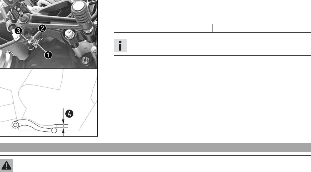
13 BRAKE SYSTEM 112
F00751-11
–Detach spring 1.
–Release nut 2and use screw 3to adjust the specified free travel A.
Guideline
Free travel at foot brake lever 3… 5 mm (0.12… 0.2 in)
Info
The range of adjustment is limited.
–Hold screw 3and tighten nut 2.
–Attach spring 1.
13.8 Checking the rear brake fluid level
Warning
Danger of accidents An insufficient brake fluid level will cause the brake system to fail.
If the brake fluid level drops below the MIN marking, the brake system is leaking or the brake linings are worn down.
–Check the brake system and do not continue riding until the problem is eliminated. (Your authorized KTM workshop will be glad
to help.)
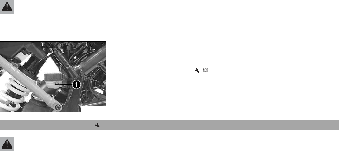
13 BRAKE SYSTEM 113
Warning
Danger of accidents Old brake fluid reduces the braking effect.
–Make sure that brake fluid for the front and rear brake is changed in accordance with the service schedule. (Your authorized
KTM workshop will be glad to help.)
F00749-10
–Stand the vehicle upright.
–Check the brake fluid level of the brake fluid reservoir.
»If the fluid level reaches the MIN marking 1:
–Add rear brake fluid. ( p. 113)
13.9 Adding rear brake fluid
Warning
Danger of accidents An insufficient brake fluid level will cause the brake system to fail.
If the brake fluid level drops below the MIN marking, the brake system is leaking or the brake linings are worn down.
–Check the brake system and do not continue riding until the problem is eliminated. (Your authorized KTM workshop will be glad
to help.)
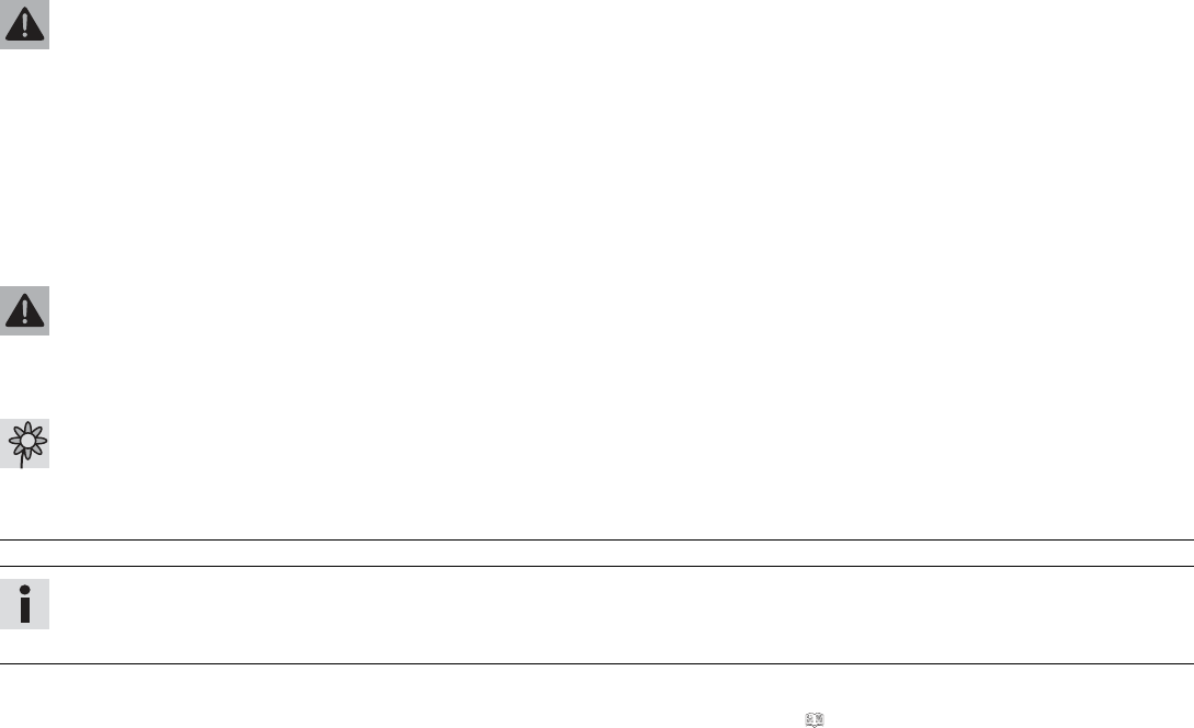
13 BRAKE SYSTEM 114
Warning
Skin irritation Brake fluid causes skin irritation.
–Keep brake fluid out of the reach of children.
–Wear suitable protective clothing and safety glasses.
–Do not allow brake fluid to come into contact with the skin, the eyes or clothing.
–Consult a doctor immediately if brake fluid has been swallowed.
–Rinse the affected area with plenty of water in the event of contact with the skin.
–Rinse eyes thoroughly with water immediately and consult a doctor if brake fluid comes into contact with the eyes.
–If brake fluid spills on to your clothing, change the clothing.
Warning
Danger of accidents Old brake fluid reduces the braking effect.
–Make sure that brake fluid for the front and rear brake is changed in accordance with the service schedule. (Your authorized
KTM workshop will be glad to help.)
Warning
Environmental hazard Hazardous substances cause environmental damage.
–Dispose of oils, grease, filters, fuel, cleaning agents, brake fluid, etc., correctly and in compliance with the applicable regula-
tions.
Info
Avoid contact between brake fluid and painted parts. Brake fluid attacks paint.
Only use clean brake fluid from a sealed container.
Preparatory work
–Check the brake linings of the rear brake. ( p. 116)
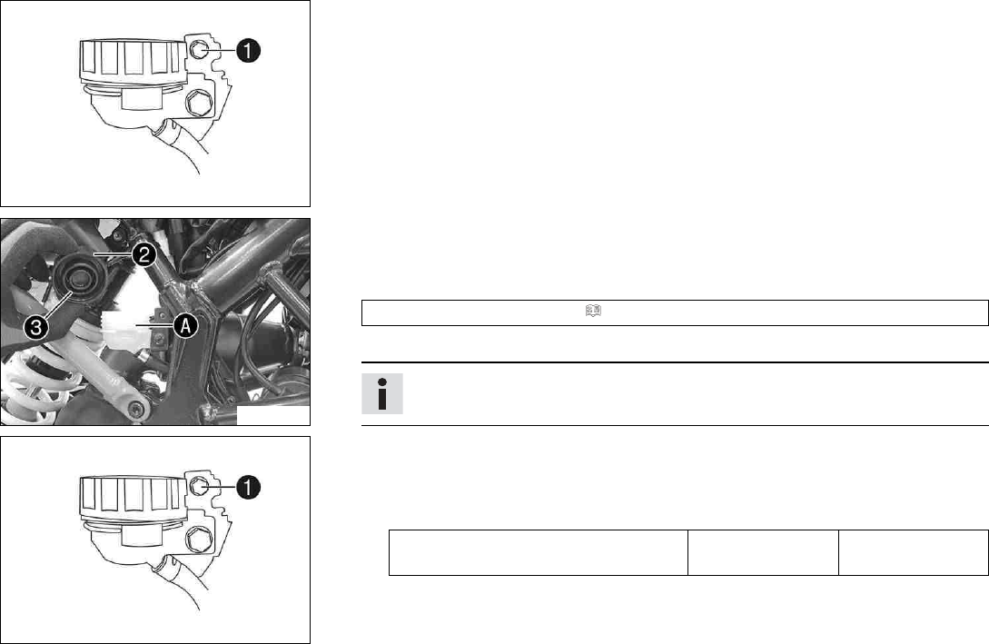
13 BRAKE SYSTEM 115
H01142-10
Condition
The screw cap is locked.
–Remove screw 1and take off the screw cap lock.
F00750-10
–Stand the vehicle upright.
–Remove screw cap 2with membrane 3.
–Add brake fluid to level A.
Brake fluid DOT 4 / DOT 5.1 ( p. 185)
–Mount screw cap with membrane.
Info
Clean up overflowed or spilled brake fluid immediately with water.
H01142-10
Condition
The screw cap is locked.
–Position the screw cap lock and mount and tighten screw 1.
Guideline
Screw, compensating tank cap lock,
rear brake
M5 9 Nm (6.6 lbf ft)
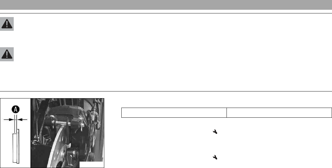
13 BRAKE SYSTEM 116
13.10 Checking the brake linings of the rear brake
Warning
Danger of accidents Worn-out brake linings reduce the braking effect.
–Ensure that worn-out brake linings are replaced immediately. (Your authorized KTM workshop will be glad to help.)
Warning
Danger of accidents Damaged brake discs reduce the braking effect.
If the brake linings are not changed in time, the brake lining carriers grind against the brake disc. As a consequence, the braking
effect is greatly reduced and the brake discs are destroyed.
–Check the brake linings regularly.
F00753-10
–Check the brake linings for minimum thickness A.
Minimum thickness A≥1 mm (≥0.04 in)
» If the minimum thickness is less than specified:
–Change the rear brake linings.
–Check the brake linings for damage and cracking.
» If there is damage or cracking:
–Change the rear brake linings.
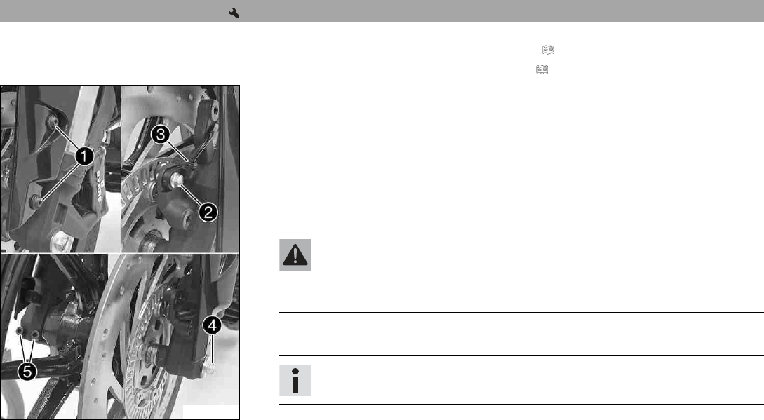
14 WHEELS, TIRES 117
14.1 Removing the front wheel
Preparatory work
–Raise the motorcycle with the rear lifting gear. ( p. 88)
–Lift the motorcycle with the front lifting gear. ( p. 89)
F00754-10
Main work
–Remove screws 1with washers and push the fender slightly to the side.
–Remove screw 2and pull wheel speed sensor 3out of the hole.
–Loosen screw 4by several rotations.
–Loosen screws 5.
–Press on screw 4to push the wheel spindle out of the axle clamp.
–Remove screw 4.
Warning
Danger of accidents Reduced braking effect caused by damaged brake discs.
–Always lay the wheel down in such a way that the brake discs are not dam-
aged.
–Holding the front wheel, withdraw the wheel spindle. Take the front wheel out of the
fork.
Info
Do not pull the hand brake lever when the front wheel is removed.
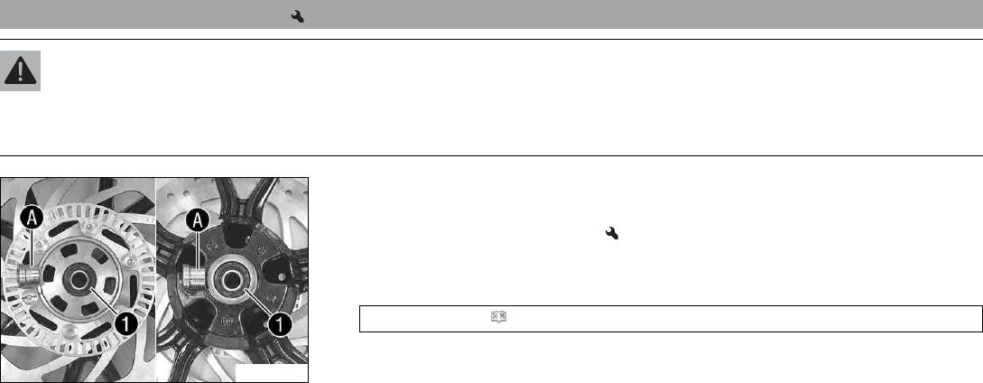
14 WHEELS, TIRES 118
14.2 Installing the front wheel
Warning
Danger of accidents Oil or grease on the brake discs reduces the braking effect.
–Always keep the brake discs free of oil and grease.
–Clean the brake discs with brake cleaner when necessary.
F00755-10
–Check the wheel bearing for damage and wear.
» If the wheel bearing is damaged or worn:
–Change the wheel bearing.
–Remove the spacers.
–Clean and grease shaft seal rings 1and contact surfaces Aof the spacers.
Long-life grease ( p. 188)
–Insert the spacers.
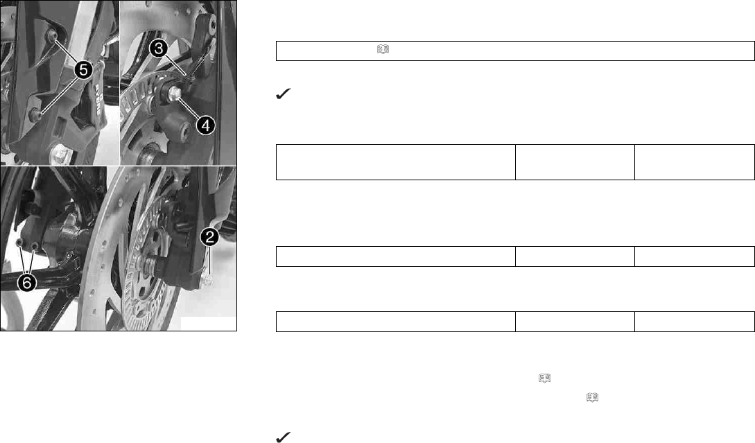
14 WHEELS, TIRES 119
F00754-11
–Clean the thread of the wheel spindle and screw 2.
–Clean and grease wheel spindle.
Long-life grease ( p. 188)
–Position the front wheel and insert the wheel spindle.
The brake linings are correctly positioned.
–Mount and tighten screw 2.
Guideline
Screw, front wheel spindle M8 25 Nm
(18.4 lbf ft)
–Position wheel speed sensor 3in the drill hole.
–Mount and tighten screw 4.
Guideline
Screw, wheel speed sensor holder M6 8 Nm (5.9 lbf ft)
–Mount and tighten screws 5with the washers.
Guideline
Screw, front fender M6 7 Nm (5.2 lbf ft)
–Operate the hand brake lever repeatedly until the brake linings are in contact with the
brake disc and there is a pressure point.
–Take the motorcycle from the front lifting gear. ( p. 90)
–Remove the rear of the motorcycle from the lifting gear. ( p. 88)
–Operate the front brake and compress the fork a few times firmly.
The fork legs straighten.
–Tighten screws 6.
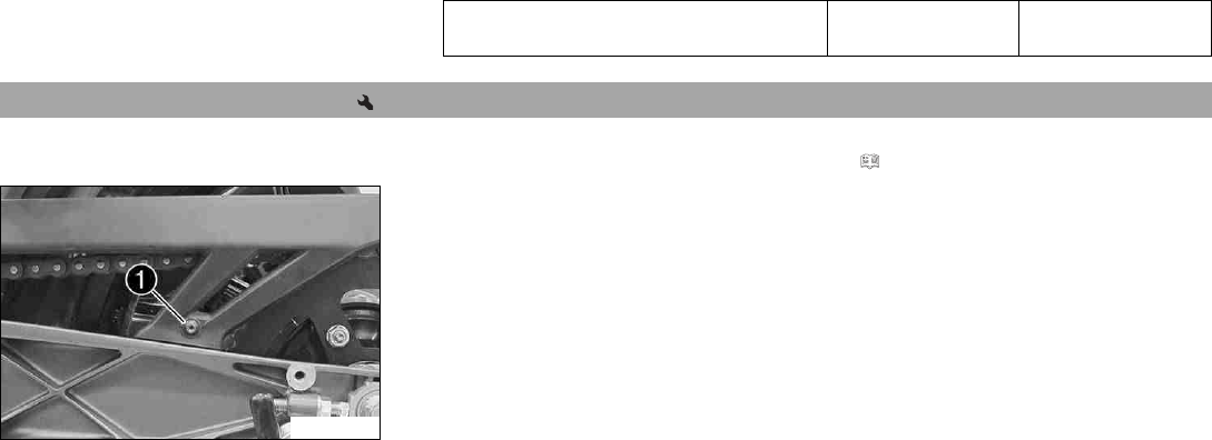
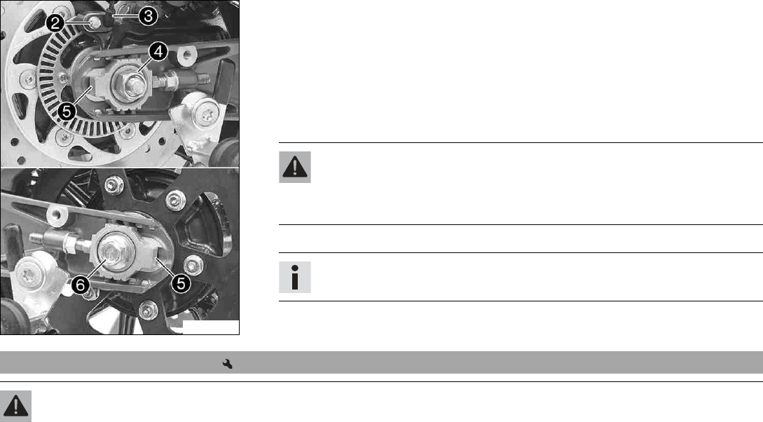
14 WHEELS, TIRES 121
F00745-11
–Remove screw 2and pull wheel speed sensor 3out of the hole.
–Remove nut 4and washer.
–Remove chain adjuster 5.
–Holding the rear wheel, withdraw wheel spindle 6with the washer and chain
adjuster 5.
–Push the rear wheel forward as far as possible and take the chain off the rear sprocket.
–Push chain guard to the side.
Warning
Danger of accidents Reduced braking effect caused by damaged brake discs.
–Always lay the wheel down in such a way that the brake discs are not dam-
aged.
–Pull the rear wheel back and take it out of the swingarm.
Info
Do not operate the foot brake lever when the rear wheel is removed.
14.4 Installing the rear wheel
Warning
Danger of accidents Oil or grease on the brake discs reduces the braking effect.
–Always keep the brake discs free of oil and grease.
–Clean the brake discs with brake cleaner when necessary.

14 WHEELS, TIRES 122
Warning
Danger of accidents There is no braking effect to start with at the rear brake after installing the rear wheel.
–Actuate the foot brake several times before going on a ride until you can feel a firm pressure point.
F00757-10
Main work
–Check the wheel bearing for damage and wear.
» If the wheel bearing is damaged or worn:
–Change the wheel bearing.
–Remove the spacers.
–Clean and grease shaft seal rings 1and contact surfaces Aof the spacers.
Long-life grease ( p. 188)
–Clean the thread of the wheel spindle and axle nut.
–Clean and grease wheel spindle.
Long-life grease ( p. 188)
–Clean the mating surfaces of the brake caliper support and swingarm.
–Install the rubber damper and rear sprocket carrier on the rear wheel.
–Insert the spacers.
–Position the rear wheel.
The brake linings are correctly positioned.
–Push the rear wheel forward as far as possible and lay the chain on the rear sprocket.
–Position the chain guard.
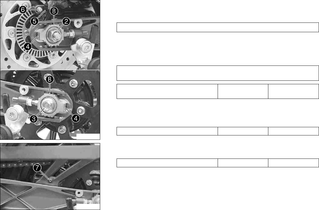
14 WHEELS, TIRES 123
F00745-12
–Pull the rear wheel back and mount wheel spindle 3with the washer and chain
adjuster 4.
Guideline
Mount left and right chain adjusters 4in the same position.
–Mount nut 2and washer.
–Push the rear wheel forward so that the chain adjusters are in contact with the screws,
and tighten nut 2.
Guideline
In order for the rear wheel to be correctly aligned, the markings on the left and right
chain adjusters must be in the same position relative to reference markings B.
Nut, rear wheel spindle M14x1.5 98 Nm
(72.3 lbf ft)
–Position wheel speed sensor 5in the drill hole.
–Mount and tighten screw 6.
Guideline
Screw, wheel speed sensor holder M6 8 Nm (5.9 lbf ft)
F00776-11
–Mount and tighten screw 7.
Guideline
Screw, chain guard EJOT PT®K60x30 7 Nm (5.2 lbf ft)
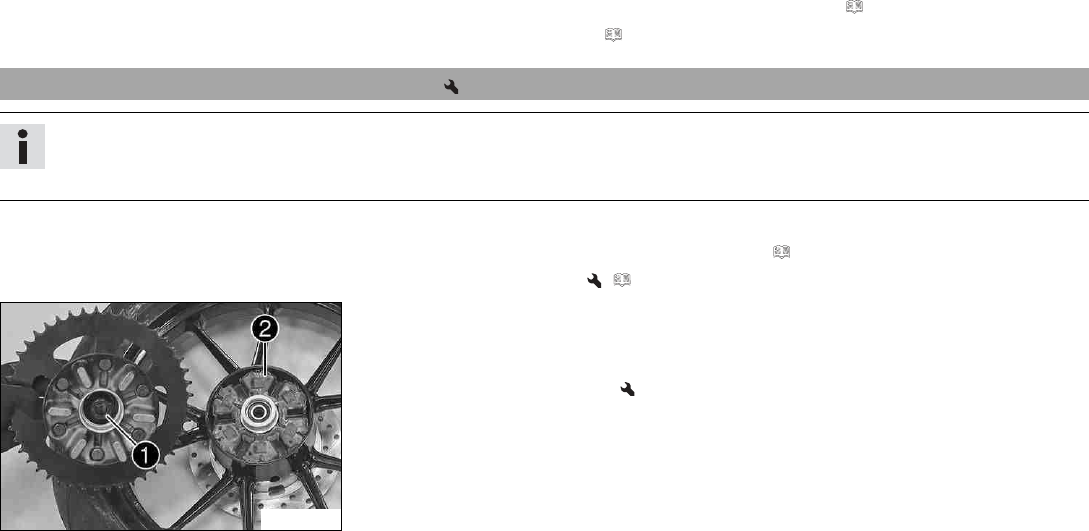
14 WHEELS, TIRES 124
Finishing work
–Remove the rear of the motorcycle from the lifting gear. ( p. 88)
–Check the chain tension. ( p. 96)
14.5 Checking the rear hub rubber dampers
Info
The engine power is transmitted from the rear sprocket to the rear wheel via 6 rubber dampers. They eventually wear out during
operation. If the rubber dampers are not changed in time, the rear sprocket carrier and the rear hub will be damaged.
Preparatory work
–Raise the motorcycle with the rear lifting gear. ( p. 88)
–Remove the rear wheel. ( p. 120)
F00756-10
Main work
–Check bearing 1.
» If the bearing is damaged or worn:
–Change the bearing.
–Check the rubber dampers 2of the rear hub for damage and wear.
» If the rubber dampers of the rear hub are damaged or worn:
–Change all rubber dampers in the rear hub.
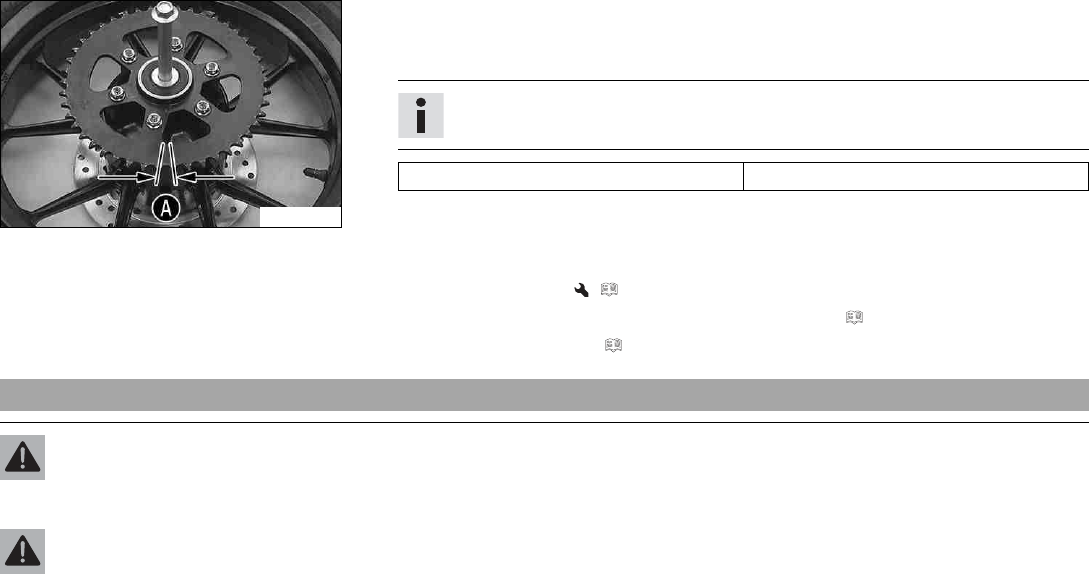
14 WHEELS, TIRES 125
S00678-10
–Lay the read wheel on a workbench with the rear sprocket facing upwards and insert the
wheel spindle in the hub.
–To check the play A, hold the rear wheel tight and try to rotate the rear sprocket.
Info
Measure the play on the outside of the rear sprocket.
Play in rubber dampers, rear wheel ≤5 mm (≤0.2 in)
»If play Ais larger than the specified value:
–Change all rubber dampers in the rear hub.
Finishing work
–Install the rear wheel. ( p. 121)
–Remove the rear of the motorcycle from the lifting gear. ( p. 88)
–Check the chain tension. ( p. 96)
14.6 Checking the tire condition
Warning
Danger of accidents If a tire bursts while riding, the vehicle becomes uncontrollable.
–Ensure that damaged or worn tires are replaced immediately. (Your authorized KTM workshop will be glad to help.)
Warning
Danger of crashing Different tire tread patterns on the front and rear wheel impair the handling characteristic.
Different tire tread patterns can make the vehicle significantly more difficult to control.
–Make sure that only tires with a similar tire tread pattern are fitted to the front and rear wheel.
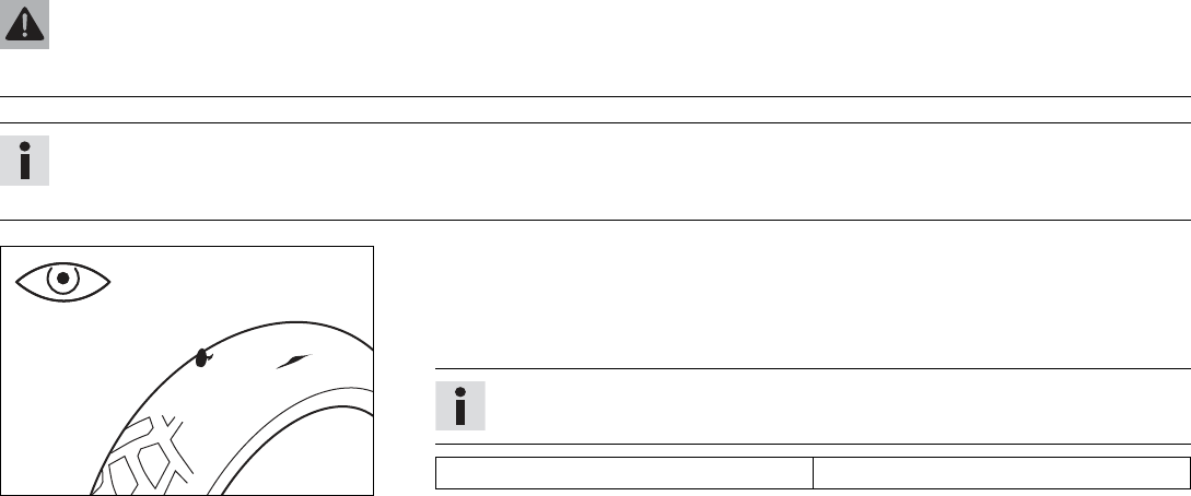
14 WHEELS, TIRES 126
Warning
Danger of accidents Non-approved or non-recommended tires and wheels impact the handling characteristic.
–Only use tires/wheels approved by KTM with the corresponding speed index.
Info
The type, condition, and air pressure of the tires all have a major impact on the handling characteristics of the motorcycle.
Worn tires have a negative effect on handling characteristics, especially on wet surfaces.
400602-10
–Check the front and rear tires for cuts, run-in objects, and other damage.
» If the tires have cuts, run-in objects, or other damage:
–Change the tires.
–Check the tread depth.
Info
Adhere to the legally required minimum tread depth.
Minimum tread depth ≥2 mm (≥0.08 in)
» If the tread depth is less than the minimum tread depth:
–Change the tires.
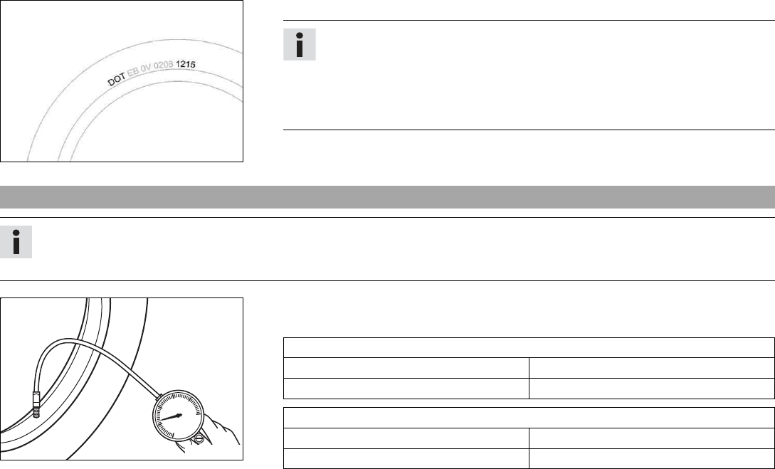
14 WHEELS, TIRES 127
H01144-10
–Check the tire age.
Info
The tire date of manufacture is usually contained in the tire label and is indi-
cated by the last four digits of the DOT number. The first two digits indicate the
week of manufacture and the last two digits the year of manufacture.
KTM recommends that the tires be changed after 5 years at the latest, regard-
less of the actual state of wear.
» If the tires are more than 5 years old:
–Change the tires.
14.7 Checking the tire air pressure
Info
Low tire air pressure leads to abnormal wear and overheating of the tire.
Correct tire air pressure ensures optimal riding comfort and maximum tire service life.
400695-01
–Remove the dust cap.
–Check tire air pressure when the tires are cold.
Tire air pressure, solo
Front 2.0 bar (29 psi)
Rear 2.0 bar (29 psi)
Tire air pressure with passenger/full payload
Front 2.0 bar (29 psi)
Rear 2.2 bar (32 psi)
» If the tire air pressure does not meet specifications:
14 WHEELS, TIRES 128
–Correct the tire air pressure.
–Mount the dust cap.
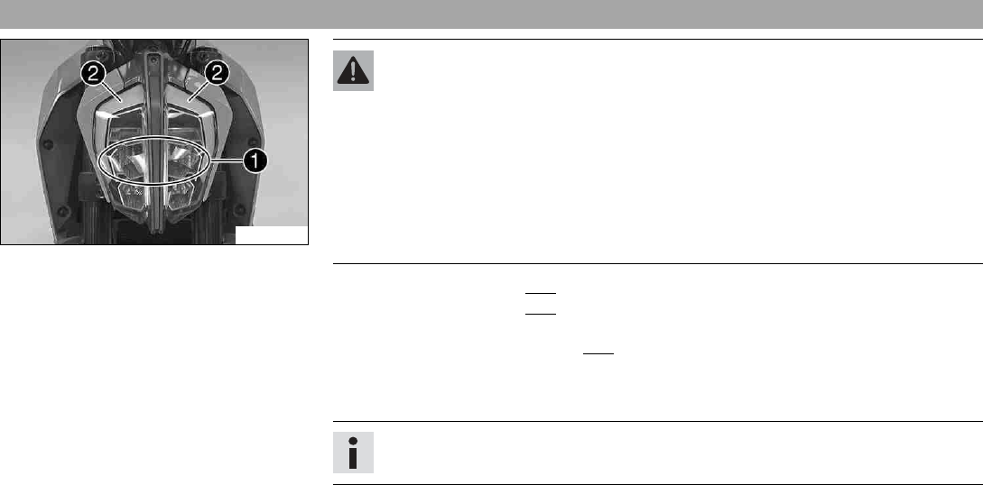
15 ELECTRICAL SYSTEM 129
15.1 Daytime running light (DRL)
F00850-11
Warning
Danger of accidents When visibility is poor, the daytime running light is not a sub-
stitute for the low beam.
Automatic switching between the daytime running light and low beam may only be
partially available when visibility is significantly impaired due to fog, snow or rain.
–Ensure that the appropriate type of lighting is always selected.
–If necessary switch off the daytime running lights using the menu before going
on a ride or when stopped so that the low beam is switched on permanently.
–Note the legal regulations regarding the daytime running light.
The daytime running light (DRL) 1is integrated in the main headlight.
The daytime running light (DRL) must only be switched on when visibility conditions are
good.
Activate the daytime running light (DRL) in the combination instrument.
Control is provided by the brightness sensor in the combination instrument. When visibility
conditions are good, the low beam is switched off and the daytime running light is switched
on.
Info
The position light 2lights up with all types of lighting.
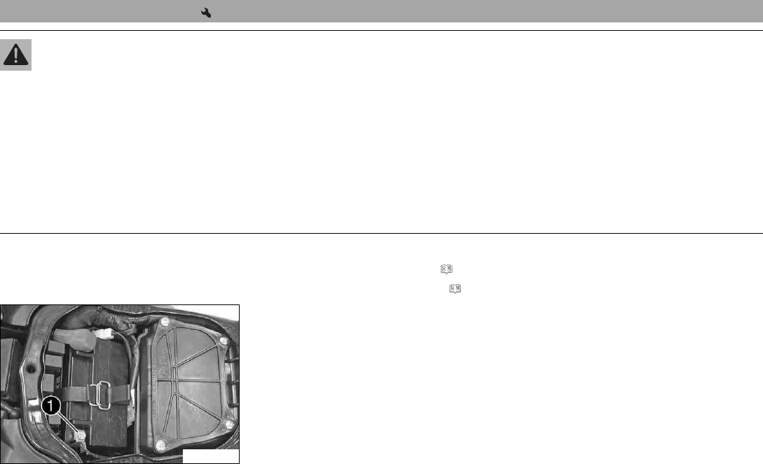
15 ELECTRICAL SYSTEM 130
15.2 Removing the battery
Warning
Risk of injury Battery acid and battery gases cause serious chemical burns.
–Keep batteries out of the reach of children.
–Wear suitable protective clothing and safety glasses.
–Avoid contact with battery acid and battery gases.
–Keep sparks or open flames away from the battery.
–Only charge batteries in well-ventilated rooms.
–Rinse the affected area immediately with plenty of water in the event of contact with the skin.
–Rinse eyes with water for at least 15 minutes and consult a doctor immediately if battery acid and battery gases get into the
eyes.
Preparatory work
–Remove the passenger seat. ( p. 92)
–Remove the front rider's seat. ( p. 93)
F00774-10
Main work
–Disconnect negative cable 1from the battery.
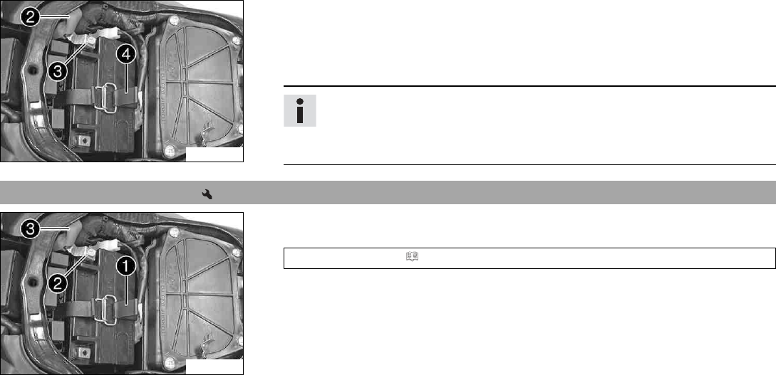
15 ELECTRICAL SYSTEM 131
F00775-10
–Pull back positive terminal cover 2.
–Disconnect positive cable 3from the battery.
–Detach rubber band 4.
–Pull the battery up and out of the battery holder.
Info
Never operate the motorcycle with a discharged battery or without a battery. In
both cases, electrical components and safety devices can be damaged. The vehi-
cle will therefore no longer be roadworthy.
15.3 Installing the battery
F00775-11
Main work
–Position the battery in the battery holder.
Battery (ETZ-9-BS) ( p. 175)
–Reconnect rubber band 1.
–Position positive cable 2and mount and tighten the screw.
–Position positive terminal cover 3.
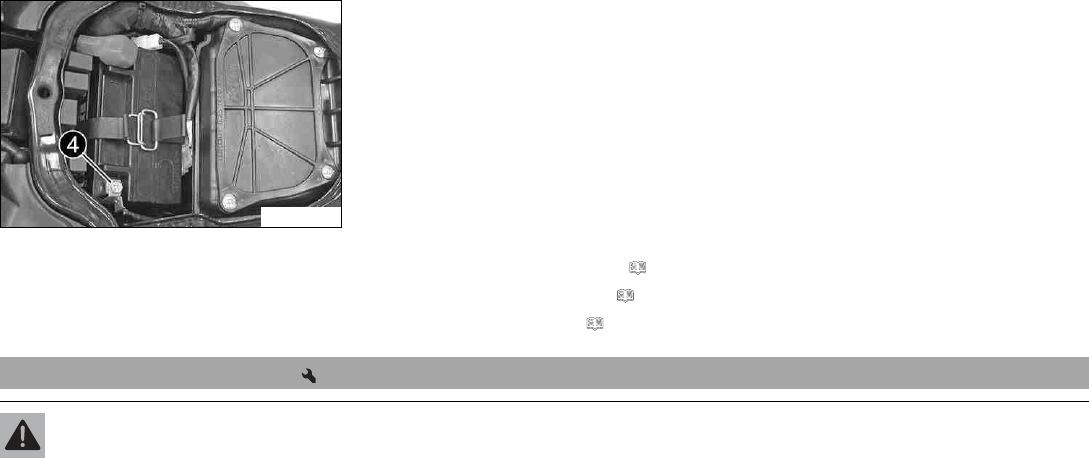
15 ELECTRICAL SYSTEM 132
F00774-11
–Position negative cable 4; mount and tighten the screw.
Finishing work
–Mount the front rider's seat. ( p. 94)
–Mount the passenger seat. ( p. 93)
–Set the time and date. ( p. 60)
15.4 Recharging the battery
Warning
Risk of injury Battery acid and battery gases cause serious chemical burns.
–Keep batteries out of the reach of children.
–Wear suitable protective clothing and safety glasses.
–Avoid contact with battery acid and battery gases.
–Keep sparks or open flames away from the battery.
–Only charge batteries in well-ventilated rooms.
–Rinse the affected area immediately with plenty of water in the event of contact with the skin.
–Rinse eyes with water for at least 15 minutes and consult a doctor immediately if battery acid and battery gases get into the
eyes.
15 ELECTRICAL SYSTEM 133
Warning
Environmental hazard Batteries contain environmentally-hazardous materials.
–Do not dispose of batteries as household waste.
–Dispose of batteries at a collection point for used batteries.
Info
Even when there is no load on the battery, it discharges steadily.
The charging level and the method of charging are very important for the service life of the battery.
Rapid recharging with a high charging current shortens the battery's service life.
If the charging current, charging voltage, or charging time is exceeded, electrolyte escapes through the safety valves. This reduces
the battery capacity.
If the battery is depleted from starting the vehicle repeatedly, the battery must be charged immediately.
If the battery is left in a discharged state for an extended period, it will become over-discharged and sulfate, destroying the battery.
The battery is maintenance-free. The acid level does not have to be checked.
Preparatory work
–Switch off all power consumers and switch off the engine.
–Remove the passenger seat. ( p. 92)
–Remove the front rider's seat. ( p. 93)
–Disconnect the negative cable of the battery to avoid damage to the onboard electron-
ics.
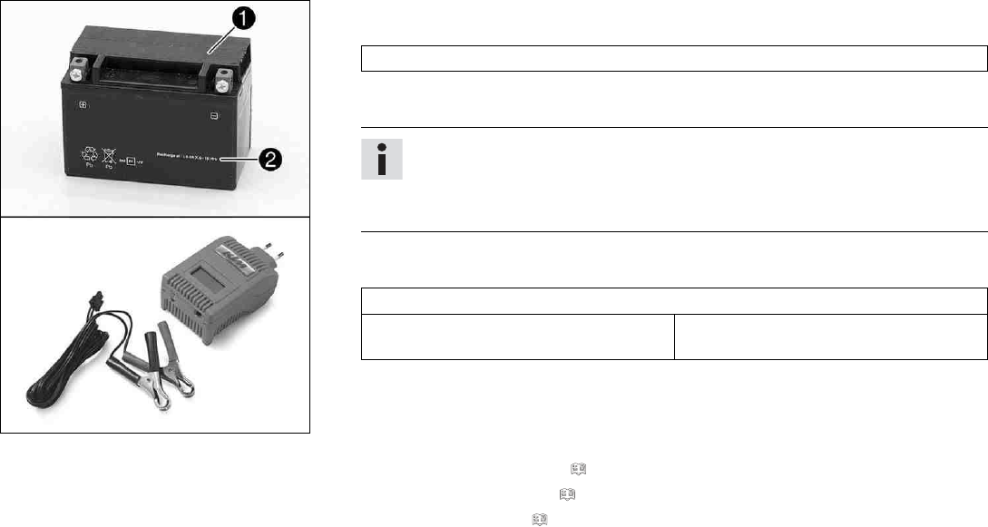
15 ELECTRICAL SYSTEM 134
M00729-10
Main work
–Connect the battery charger to the battery. Switch on the battery charger.
Battery charger (58429074000)
You can also use the battery charger to test rest potential and start potential of the bat-
tery, and to test the alternator. With this device, you cannot overcharge the battery.
Info
Never remove lid 1.
Charge the battery with a maximum of 10% of the capacity specified on battery
housing 2.
–Switch off the battery charger after charging and disconnect from the battery.
Guideline
The charge current, charge voltage and charge time must not be exceeded.
Charge the battery regularly when the
motorcycle is not in use
3 months
–Position the negative cable and mount and tighten the screw.
–Position the negative terminal cover.
Finishing work
–Mount the front rider's seat. ( p. 94)
–Mount the passenger seat. ( p. 93)
–Set the time and date. ( p. 60)
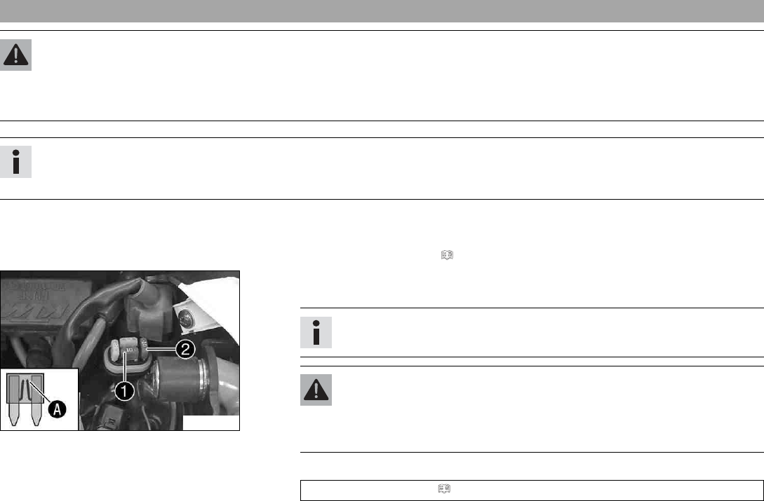
15 ELECTRICAL SYSTEM 135
15.5 Changing the ABS fuses
Warning
Fire hazard Incorrect fuses overload the electrical system.
–Only use fuses with the required ampere value.
–Do not bypass or repair fuses.
Info
Two fuses for the ABS are located under the passenger seat. These fuses protect the return pump and the hydraulic unit of the
ABS. The third fuse, which protects the ABS control unit, is located in the fuse box.
Preparatory work
–Switch off all power consumers and the engine.
–Remove the passenger seat. ( p. 92)
F00758-10
To change the fuse of the ABS hydraulic unit:
–Take off the protection cap and remove fuse 1.
Info
You can recognize a faulty fuse by a burned-out fuse wire A.
Warning
Fire hazard Incorrect fuses overload the electrical system.
–Only use fuses with the required ampere value.
–Do not bypass or repair fuses.
–Use spare fuses with the correct rating only.
Fuse (75011088010) ( p. 175)
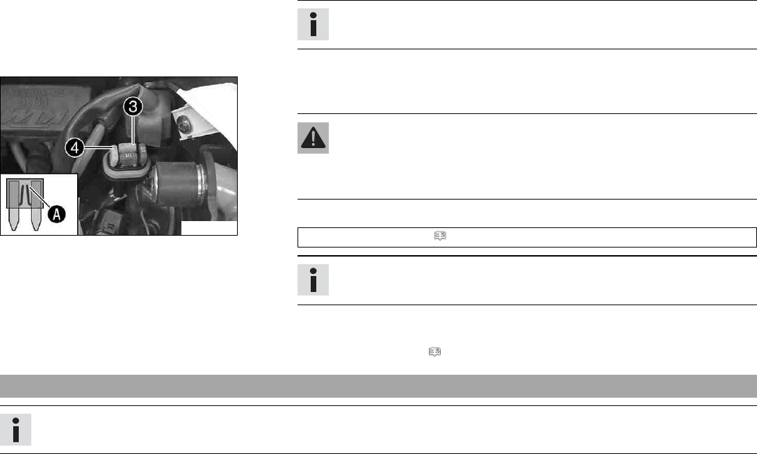
15 ELECTRICAL SYSTEM 136
Tip
Replace spare fuse 2in the fuse box so that it is available if needed.
–Mount the protection cap.
F00758-11
To change the fuse of the ABS return pump:
–Take off the protection cap and remove fuse 3.
Warning
Fire hazard Incorrect fuses overload the electrical system.
–Only use fuses with the required ampere value.
–Do not bypass or repair fuses.
–Use spare fuses with the correct rating only.
Fuse (90111088025) ( p. 175)
Tip
Replace spare fuse 4in the fuse box so that it is available if needed.
–Mount the protection cap.
Finishing work
–Mount the passenger seat. ( p. 93)
15.6 Changing the fuses of individual power consumers
Info
The fuse box with the main fuse and the fuses of the individual power consumers is located under the passenger seat.
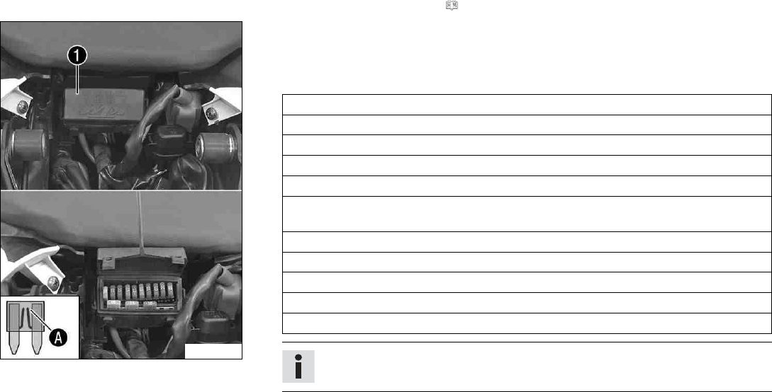
15 ELECTRICAL SYSTEM 137
Preparatory work
–Switch off all power consumers and switch off the engine.
–Remove the passenger seat. ( p. 92)
F00849-10
Main work
–Open fuse box cover 1.
–Remove the defective fuse.
Guideline
Fuse 1- 30 A - main fuse
Fuse 2- 10 A - combination instrument
Fuse 3- 10 A - power relay
Fuse 4- 15 A - ignition coil, fuel pump, start auxiliary relay, horn
Fuse 5- 10 A - radiator fan
Fuse 6- 15 A - brake light, turn signal, high beam, low beam, parking light, tail light,
license plate lamp
Fuse 7- 10 A - control unit, ABS control unit
Fuse 8- 10 A - alarm system (optional)
Fuse 9- 10 A - auxiliary equipment
Fuse 10 - 10 A - auxiliary equipment
Fuse SPARE - 10 A/15 A/30 A - spare fuses
Info
You can recognize a faulty fuse by a burned-out fuse wire A.
15 ELECTRICAL SYSTEM 138
Warning
Fire hazard Incorrect fuses overload the electrical system.
–Only use fuses with the required ampere value.
–Do not bypass or repair fuses.
–Use spare fuses with the correct rating only.
Fuse (75011088010) ( p. 175)
Fuse (75011088015) ( p. 175)
Fuse (75011088030) ( p. 175)
Tip
Replace the spare fuse in the fuse box so that it is available if needed.
–Check that the power consumer is functioning properly.
–Close the fuse box cover 1.
Finishing work
–Mount the passenger seat. ( p. 93)
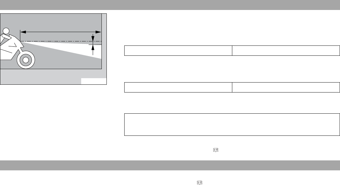
15 ELECTRICAL SYSTEM 139
15.7 Checking the headlight setting
0
0
AA
0
0
BB
400726-10
–Position the vehicle upright on a horizontal surface in front of a light wall and make a
mark at the height of the center of the low beam headlight.
–Make another mark at a distance Bunder the first mark.
Guideline
Distance B5 cm (2 in)
–Position the vehicle perpendicular to the wall at a distance Afrom the wall and switch
on the low beam.
Guideline
Distance A5 m (16 ft)
–The rider, with luggage and passenger if applicable, now mounts the motorcycle.
–Check the headlight setting.
The light-dark boundary must lie exactly on the lower mark when the motorcycle is
ready to operate with the rider mounted along with any luggage and a passenger if
applicable.
» If the boundary between light and dark does not meet specifications:
–Adjust the headlight range. ( p. 139)
15.8 Adjusting the headlight range
Preparatory work
–Check the headlight setting. ( p. 139)
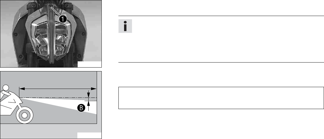
15 ELECTRICAL SYSTEM 140
F00850-10
Main work
–Turn adjusting screw 1to adjust the headlight range.
Info
Turn clockwise to increase the headlight range; turn counterclockwise to reduce
the headlight range.
If you have a payload, you may have to correct the headlight range.
Screw 1also secures the headlight. Ensure the screw is always screwed in far
enough.
400726-11
–Set the headlight to marking B.
Guideline
The light-dark boundary must lie exactly on lower mark Bwhen the motorcycle is
ready to operate with the rider mounted along with any luggage and a passenger if
applicable.
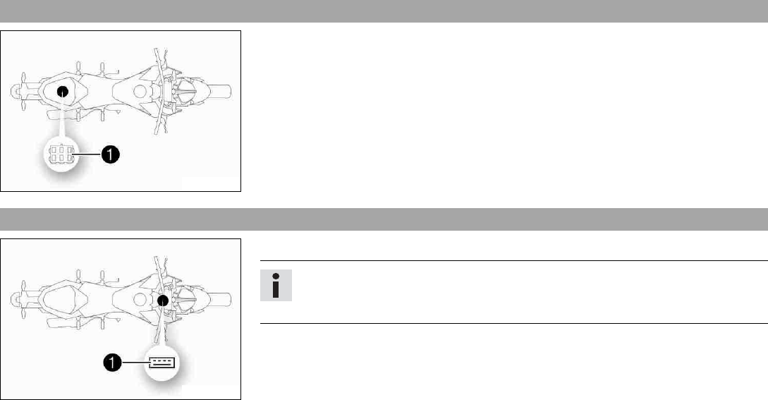
15 ELECTRICAL SYSTEM 141
15.9 Diagnostics connector
H01906-10
Diagnostics connector 1is located under the passenger seat.
15.10 USB diagnostics plug
H01907-10
The USB diagnostics plug 1is located under the combination instrument.
Info
The USB diagnostics plug is intended for diagnostics purposes only and is not suit-
able for supplying power to external devices.
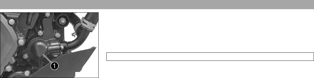
16 COOLING SYSTEM 142
16.1 Cooling system
F00762-10
Water pump 1in the engine ensures forced circulation of the coolant.
The pressure resulting from the warming of the cooling system is regulated by a valve in
radiator cap 2. Heat expansion causes excess coolant to flow into compensating tank 3.
When the temperature falls, this surplus coolant is sucked back into the cooling system.
This ensures that operating the vehicle at the specified coolant temperature will not result
in a risk of malfunctions.
110 °C (230 °F)
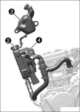
16 COOLING SYSTEM 143
H01904-10
The coolant is cooled by the air stream and a radiator fan 4, which is controlled by a ther-
moswitch.
The lower the speed, the less the cooling effect. Dirty cooling fins also reduce the cooling
effect.
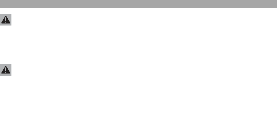
16 COOLING SYSTEM 144
16.2 Checking the antifreeze and coolant level
Warning
Danger of scalding During motorcycle operation, the coolant gets very hot and is under pressure.
–Do not open the radiator, the radiator hoses or other cooling system components if the engine or the cooling system are at oper-
ating temperature.
–Allow the cooling system and the engine to cool down before you open the radiator, the radiator hoses or other components of
the cooling system.
–In the event of scalding, rinse the area affected immediately with lukewarm water.
Warning
Danger of poisoning Coolant is toxic and a health hazard.
–Keep coolant out of the reach of children.
–Do not allow coolant to come into contact with the skin, the eyes and clothing.
–Consult a doctor immediately if coolant is swallowed.
–Rinse the affected area immediately with plenty of water in the event of contact with the skin.
–Rinse eyes thoroughly with water and consult a doctor immediately if coolant gets into the eyes.
–Change clothing if coolant spills onto your clothing.
Condition
The engine is cold.
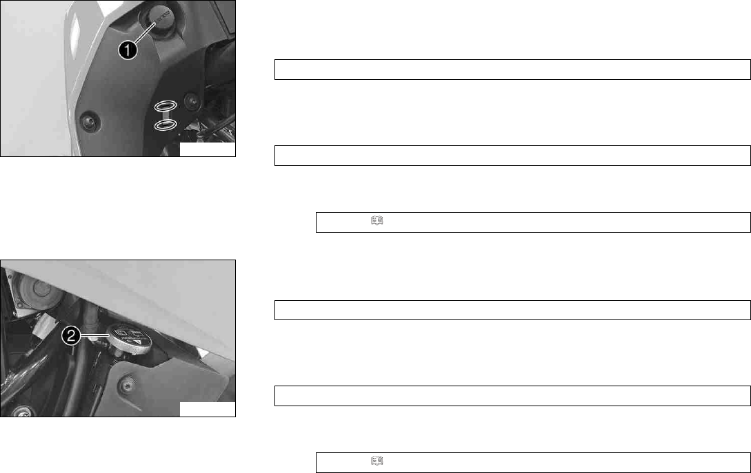
16 COOLING SYSTEM 145
F00764-10
–Stand the motorcycle upright on a horizontal surface.
–Remove cap 1of the compensating tank.
–Check the antifreeze in the coolant.
−25… −45 °C (−13… −49 °F)
» If the antifreeze in the coolant does not match the specified value:
–Correct the antifreeze in the coolant.
–Check the coolant level in the compensating tank.
The coolant level must be between the two markings.
» If the coolant level does not match the specified value:
–Correct the coolant level.
Coolant ( p. 185)
–Mount the cap of the compensating tank.
F00763-10
–Remove radiator cap 2.
–Check the antifreeze in the coolant.
−25… −45 °C (−13… −49 °F)
» If the antifreeze in the coolant does not match the specified value:
–Correct the antifreeze in the coolant.
–Check the coolant level in the radiator.
The radiator must be filled completely.
» If the coolant level does not match the specified value:
–Check the coolant level and the reason for the loss.
Coolant ( p. 185)
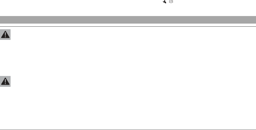
16 COOLING SYSTEM 146
» If you had to add more coolant than the specified amount:
> 0.20 l (> 0.21 qt.)
–Fill/bleed the cooling system. ( p. 149)
–Mount the radiator cap.
16.3 Checking the coolant level
Warning
Danger of scalding During motorcycle operation, the coolant gets very hot and is under pressure.
–Do not open the radiator, the radiator hoses or other cooling system components if the engine or the cooling system are at oper-
ating temperature.
–Allow the cooling system and the engine to cool down before you open the radiator, the radiator hoses or other components of
the cooling system.
–In the event of scalding, rinse the area affected immediately with lukewarm water.
Warning
Danger of poisoning Coolant is toxic and a health hazard.
–Keep coolant out of the reach of children.
–Do not allow coolant to come into contact with the skin, the eyes and clothing.
–Consult a doctor immediately if coolant is swallowed.
–Rinse the affected area immediately with plenty of water in the event of contact with the skin.
–Rinse eyes thoroughly with water and consult a doctor immediately if coolant gets into the eyes.
–Change clothing if coolant spills onto your clothing.
Condition
The engine is cold.
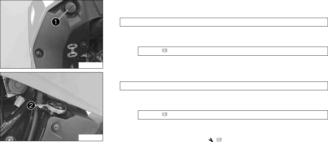
16 COOLING SYSTEM 147
F00764-10
–Stand the motorcycle upright on a horizontal surface.
–Check the coolant level in compensating tank 1.
The coolant level must be between the two markings.
» If the coolant level does not match the specified value:
–Correct the coolant level.
Coolant ( p. 185)
F00763-10
–Remove radiator cap 2and check the coolant level in the radiator.
The radiator must be filled completely.
» If the coolant level does not match the specified value:
–Check the coolant level and the reason for the loss.
Coolant ( p. 185)
» If you had to add more coolant than the specified amount:
> 0.20 l (> 0.21 qt.)
–Fill/bleed the cooling system. ( p. 149)
–Mount the radiator cap.
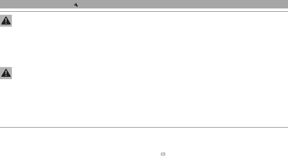
16 COOLING SYSTEM 148
16.4 Draining the coolant
Warning
Danger of scalding During motorcycle operation, the coolant gets very hot and is under pressure.
–Do not open the radiator, the radiator hoses or other cooling system components if the engine or the cooling system are at oper-
ating temperature.
–Allow the cooling system and the engine to cool down before you open the radiator, the radiator hoses or other components of
the cooling system.
–In the event of scalding, rinse the area affected immediately with lukewarm water.
Warning
Danger of poisoning Coolant is toxic and a health hazard.
–Keep coolant out of the reach of children.
–Do not allow coolant to come into contact with the skin, the eyes and clothing.
–Consult a doctor immediately if coolant is swallowed.
–Rinse the affected area immediately with plenty of water in the event of contact with the skin.
–Rinse eyes thoroughly with water and consult a doctor immediately if coolant gets into the eyes.
–Change clothing if coolant spills onto your clothing.
Condition
The engine is cold.
Preparatory work
–Remove the front spoiler. ( p. 102)
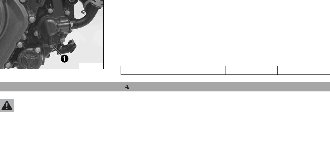
16 COOLING SYSTEM 149
F00765-10
Main work
–Position the motorcycle upright.
–Place a suitable container under the engine.
–Remove screw 1.
–Remove the radiator cap.
–Completely drain the coolant.
–Mount and tighten screw 1with a new seal ring.
Guideline
Screw plug, water pump drain hole M6 10 Nm (7.4 lbf ft)
16.5 Filling/bleeding the cooling system
Warning
Danger of poisoning Coolant is toxic and a health hazard.
–Keep coolant out of the reach of children.
–Do not allow coolant to come into contact with the skin, the eyes and clothing.
–Consult a doctor immediately if coolant is swallowed.
–Rinse the affected area immediately with plenty of water in the event of contact with the skin.
–Rinse eyes thoroughly with water and consult a doctor immediately if coolant gets into the eyes.
–Change clothing if coolant spills onto your clothing.
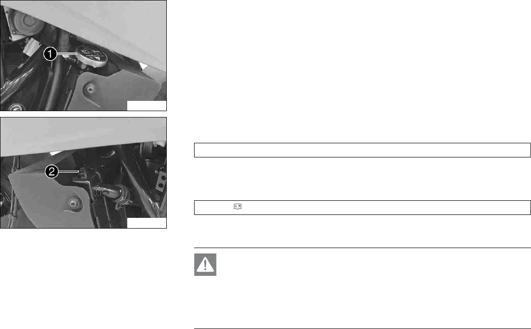
16 COOLING SYSTEM 150
F00763-11
Main work
–Remove radiator cap 1.
F00766-10
–Loosen bleeder screw 2.
Guideline
3 turns
–Tilt the vehicle slightly to the right.
–Pour in coolant until it emerges without bubbles at the bleeder screw, and then mount
and tighten the bleeder screw immediately.
Coolant ( p. 185)
–Completely fill the radiator with coolant. Mount the radiator cap.
–Rest the vehicle on the side stand.
Danger
Danger of poisoning Exhaust gases are toxic and inhaling them may result in
unconsciousness and death.
–Always make sure there is sufficient ventilation when running the engine.
–Use an effective exhaust extraction system when starting or running the
engine in an enclosed space.
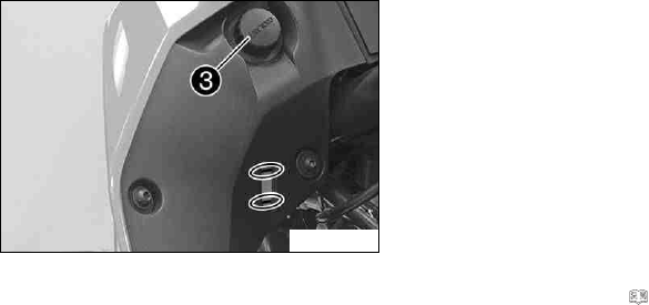
16 COOLING SYSTEM 151
–Start the engine and let it warm up.
F00764-11
–Stop the engine and allow it to cool down.
–When the engine is cool, check the coolant level in the radiator and, if necessary, add
coolant.
–Remove cap 3of the compensating tank and top up the coolant level to the upper
marking.
–Mount the cap of the compensating tank.
Finishing work
–Fit the front spoiler. ( p. 103)
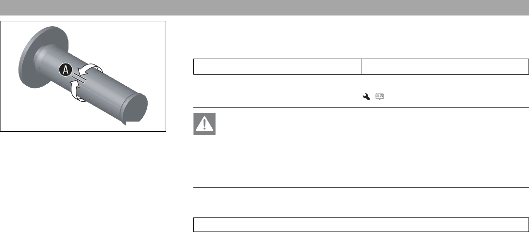
17 TUNING THE ENGINE 152
17.1 Checking the play in the throttle cable
400192-11
–Check the throttle grip for smooth operation.
–Move the handlebar to the straight-ahead position. Turn the throttle grip back and forth
slightly and determine the play in throttle cable A.
Throttle cable play A3… 5 mm (0.12… 0.2 in)
» If the throttle cable play does not meet the specified value:
–Adjust the play in the throttle cable. ( p. 153)
Danger
Danger of poisoning Exhaust gases are toxic and inhaling them may result in
unconsciousness and death.
–Always make sure there is sufficient ventilation when running the engine.
–Use an effective exhaust extraction system when starting or running the
engine in an enclosed space.
–Start the engine and let it run idle. Move the handlebar to and fro over the entire steer-
ing range.
The idle speed must not change.
» If the idle speed changes:
–Check throttle cable routing.
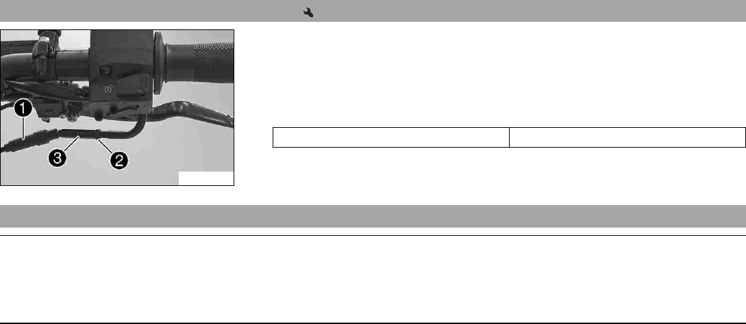
17 TUNING THE ENGINE 153
17.2 Adjusting the play in the throttle cable
F00773-10
–Move the handlebar to the straight-ahead position.
–Push back sleeve 1.
–Loosen lock nut 2.
–Adjust the play in the throttle cable by turning adjusting screw 3.
Guideline
Throttle cable play 3… 5 mm (0.12… 0.2 in)
–Tighten lock nut 2.
–Slide on sleeve 1.
17.3 Checking the clutch lever play
Note
Clutch damage If there is no play on the clutch lever, the clutch will begin to slip.
–Check the play in the clutch lever on each occasion before operating the motorcycle.
–Adjust the play in the clutch lever when necessary in accordance with the specification.
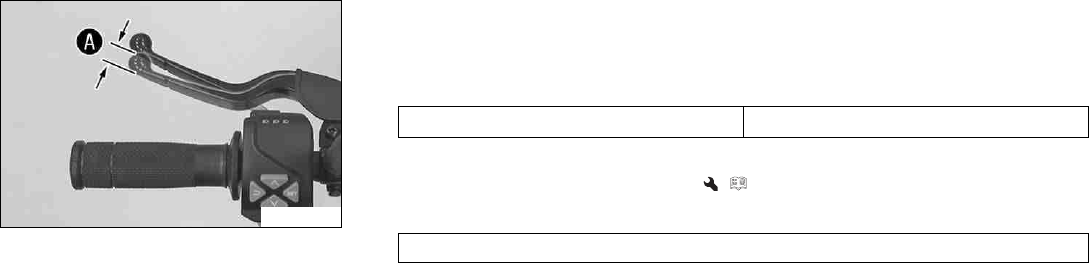
17 TUNING THE ENGINE 154
F00767-10
–Check the clutch lever for smooth operation.
–Move the handlebar to the straight-ahead position.
–Pull the clutch lever until resistance is perceptible, and determine the play in the
clutch lever A.
Clutch lever play A1… 3 mm (0.04… 0.12 in)
» If the clutch lever play does not meet the specified value:
–Adjust play in the clutch lever. ( p. 155)
–Move the handlebar to and fro over the entire steering range.
The clutch lever play must not change.
» If the clutch lever play changes:
–Check the routing of the clutch cable.
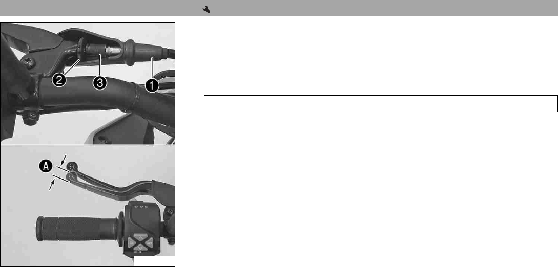
17 TUNING THE ENGINE 155
17.4 Adjusting play in the clutch lever
F00768-10
–Move the handlebar to the straight-ahead position.
–Push back sleeve 1.
–Loosen lock nut 2.
–Adjust the play in the clutch level Aby turning adjusting screw 3.
Guideline
Clutch lever play A1… 3 mm (0.04… 0.12 in)
–Tighten lock nut 2.
–Position bellows 1.
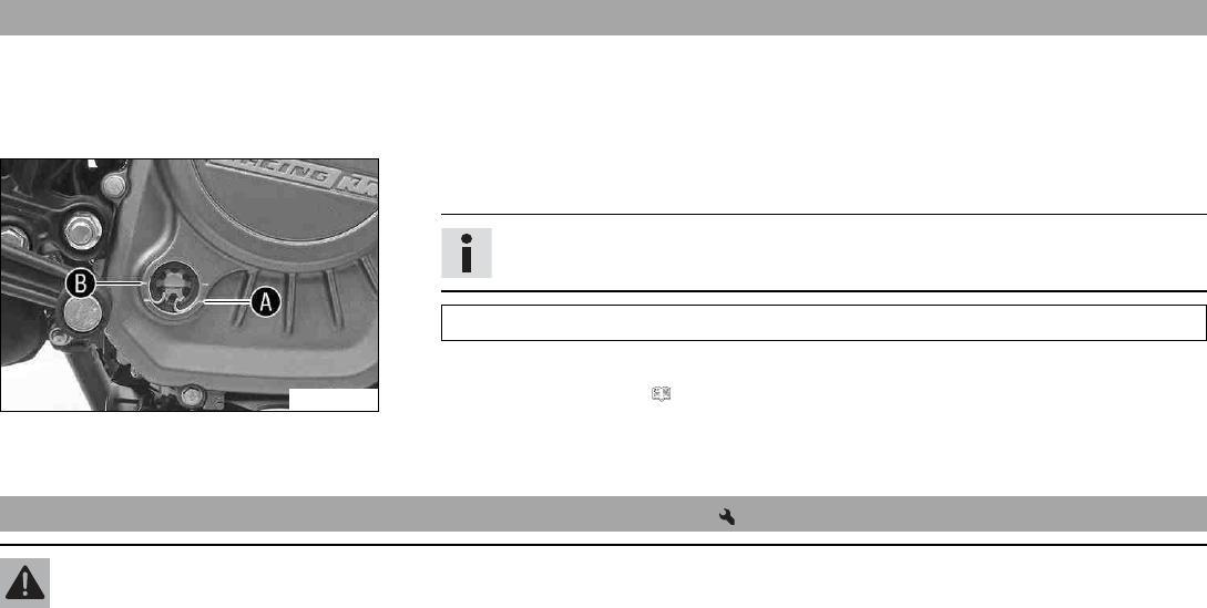
18 SERVICE WORK ON THE ENGINE 156
18.1 Checking the engine oil level
Condition
The engine is at operating temperature.
Preparatory work
–Stand the motorcycle upright on a horizontal surface.
F00772-10
Main work
–Check the engine oil level.
Info
After switching off the engine, wait one minute before checking the level.
The engine oil must be between the markings Aand B.
»If the engine oil is below the marking A:
–Add engine oil. ( p. 159)
»If the engine oil is above the marking B:
–Correct the engine oil level.
18.2 Changing the engine oil and oil filter, cleaning the oil screen
Warning
Danger of scalding Engine and gear oil get very hot when the motorcycle is ridden.
–Wear suitable protective clothing and safety gloves.
–In the event of scalding, rinse the area affected immediately with lukewarm water.
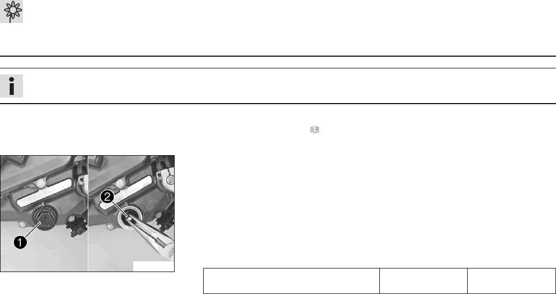
18 SERVICE WORK ON THE ENGINE 157
Warning
Environmental hazard Hazardous substances cause environmental damage.
–Dispose of oils, grease, filters, fuel, cleaning agents, brake fluid, etc., correctly and in compliance with the applicable regula-
tions.
Info
Drain the engine oil only when the engine is warm.
Preparatory work
–Remove the front spoiler. ( p. 102)
–Stand the motorcycle on its side stand on a horizontal surface.
F00769-10
Main work
–Place a suitable container under the engine.
–Remove oil drain plug 1with the O-ring.
–Remove oil screen 2with the O-ring.
–Completely drain the engine oil.
–Clean the oil drain plug and oil screen thoroughly.
–Position oil screen 2and mount and tighten oil drain plug 1with the O-ring.
Guideline
Oil drain plug M24x1.5 15 Nm
(11.1 lbf ft)
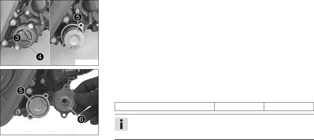
18 SERVICE WORK ON THE ENGINE 158
F00770-10
–Remove screws 3. Remove oil filter cover 4with the O-ring.
–Pull oil filter 5out of the oil filter housing.
–Completely drain the engine oil.
–Thoroughly clean the parts and sealing surface.
F00771-10
–Insert new oil filter 5.
–Lubricate the O-ring of the oil filter cover. Mount oil filter cover 6.
–Mount and tighten screws 3.
Guideline
Screw, oil filter cover M6 12 Nm (8.9 lbf ft)
Info
Too little engine oil or poor-quality engine oil results in premature wear of the
engine.
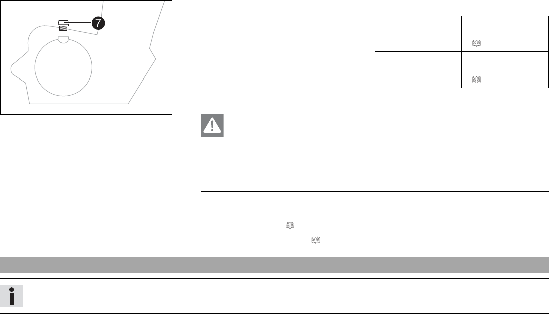
18 SERVICE WORK ON THE ENGINE 159
401955-13
–Remove filler plug 7and the O-ring from the clutch cover, and fill up with engine oil.
Engine oil 1.5 l (1.6 qt.) External temper-
ature: 0… 50 °C
(32… 122 °F)
Engine oil
(SAE 15W/50)
(p. 186)
External tempera-
ture: −10… 40 °C
(14… 104 °F)
Engine oil
(SAE 10W/40)
(p. 186)
–Install and tighten the oil filler plug with O-ring.
Danger
Danger of poisoning Exhaust gases are toxic and inhaling them may result in
unconsciousness and death.
–Always make sure there is sufficient ventilation when running the engine.
–Use an effective exhaust extraction system when starting or running the
engine in an enclosed space.
–Start the engine and check that it is oil-tight.
Finishing work
–Fit the front spoiler. ( p. 103)
–Check the engine oil level. ( p. 156)
18.3 Adding engine oil
Info
Too little engine oil or poor-quality engine oil results in premature wear of the engine.
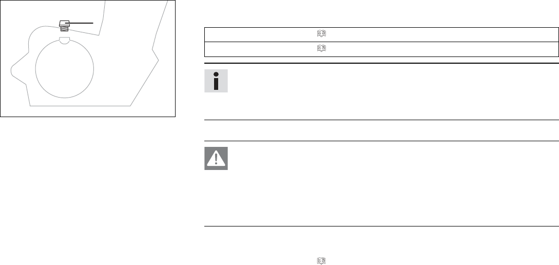
18 SERVICE WORK ON THE ENGINE 160
0
0
11
401955-10
Main work
–Remove filler plug 1and the O-ring from the clutch cover, and fill up with engine oil.
Engine oil (SAE 15W/50) ( p. 186)
Engine oil (SAE 10W/40) ( p. 186)
Info
In order to achieve optimal engine performance, it is not advisable to mix differ-
ent engine oils.
We recommended changing the engine oil when necessary.
–Install and tighten the oil filler plug with O-ring.
Danger
Danger of poisoning Exhaust gases are toxic and inhaling them may result in
unconsciousness and death.
–Always make sure there is sufficient ventilation when running the engine.
–Use an effective exhaust extraction system when starting or running the
engine in an enclosed space.
–Start the engine and check that it is oil-tight.
Finishing work
–Check the engine oil level. ( p. 156)
19 CLEANING, CARE 161
19.1 Cleaning the motorcycle
Note
Material damage Components become damaged or destroyed if a pressure cleaner is used incorrectly.
The high pressure forces water into the electrical components, connectors, throttle cables, and bearings, etc.
Pressure which is too high causes malfunctions and destroys components.
–Do not direct the water jet directly on to electrical components, connectors, throttle cables or bearings.
–Maintain a minimum distance between the nozzle of the pressure cleaner and the component.
Minimum clearance 60 cm (23.6 in)
Warning
Environmental hazard Hazardous substances cause environmental damage.
–Dispose of oils, grease, filters, fuel, cleaning agents, brake fluid, etc., correctly and in compliance with the applicable regula-
tions.
Info
If you clean the motorcycle regularly, its value and appearance will be maintained over a long period.
Avoid direct sunshine on the motorcycle during cleaning.
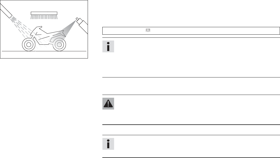
19 CLEANING, CARE 162
401061-01
–Seal the exhaust system to keep water out.
–First remove coarse dirt particles with a gentle spray of water.
–Spray very dirty areas with a normal motorcycle cleaner and then clean with a paint-
brush.
Motorcycle cleaner ( p. 188)
Info
Use warm water containing normal motorcycle cleaner and a soft sponge.
Never apply motorcycle cleaner to a dry vehicle; always rinse the vehicle with
water first.
If the vehicle was operated in road salt, clean it with cold water. Warm water
would enhance the corrosive effects of salt.
–After rinsing the motorcycle with a gentle spray of water, allow it to dry thoroughly.
–Remove the closure of the exhaust system.
Warning
Danger of accidents Moisture and dirt impair the brake system.
–Brake carefully several times to dry out and remove dirt from the brake lin-
ings and the brake discs.
–After cleaning, ride the vehicle a short distance until the engine warms up.
Info
The heat produced causes water at inaccessible locations in the engine and on
the brake system to evaporate.
–Push back the sleeves of the handlebar controls to allow any water that has penetrated
to evaporate.
–After the motorcycle has cooled off, lubricate all moving parts and bearings.
19 CLEANING, CARE 163
–Clean the chain. ( p. 95)
–Treat bare metal parts (except for brake discs and exhaust system) with anti-corrosion
materials.
Preserving materials for paints, metal and rubber ( p. 189)
–Treat all painted parts with a mild paint polish.
Perfect Finish and high gloss polish for paints ( p. 189)
Info
Do not polish parts that were matte when delivered as this would strongly impair
the material quality.
–Treat all plastic parts and powder-coated parts with a mild cleaning and care product.
Special cleaner for glossy and matte paint finishes, metal and plastic surfaces
(p. 189)
–Oil the ignition/steering lock.
Universal oil spray ( p. 189)
19.2 Checks and maintenance steps for winter operation
Info
If the motorcycle is used in the winter, salt can be expected on the roads. Precautions need to be taken against road salt corrosion.
If the vehicle was operated in road salt, clean it with cold water after riding. Warm water would enhance the corrosive effects of
salt.
19 CLEANING, CARE 164
401060-01
–Clean the motorcycle. ( p. 161)
–Clean the brakes.
Info
After EVERY trip on salted roads, thoroughly wash the brake calipers and brake
linings with cold water and dry carefully. This should be done after the parts are
cooled down and while they are installed.
After riding on salted roads, thoroughly wash the motorcycle with cold water and
dry it well.
–Treat the engine, swingarm, and all other bright and zinc-plated parts (except for the
brake discs) with a wax-based corrosion inhibitor.
Info
Corrosion inhibitor is not permitted to come in contact with the brake discs as
this would greatly reduce the braking force.
–Clean the chain. ( p. 95)
20 STORAGE 165
20.1 Storage
Info
If you want to garage the motorcycle for a longer period, take the following steps.
Before storing the motorcycle, check all parts for function and wear. If service, repairs or replacements are necessary, you should
do this during the storage period (less workshop overload). In this way, you can avoid long workshop waiting times at the start of the
new season.
401058-01
–When refueling for the last time before taking the motorcycle out of service, add fuel
additive.
Fuel additive ( p. 188)
–Refuel. ( p. 81)
–Clean the motorcycle. ( p. 161)
–Change the engine oil and oil filter, clean the oil screen. ( p. 156)
–Check the antifreeze and coolant level. ( p. 144)
–Check the tire air pressure. ( p. 127)
–Remove the battery. ( p. 130)
–Recharge the battery. ( p. 132)
Guideline
Storage temperature of battery without
direct sunlight
0… 35 °C (32… 95 °F)
–Store the vehicle in a dry location that is not subject to large fluctuations in tempera-
ture.
Info
KTM recommends jacking up the motorcycle.
–Raise the motorcycle with the rear lifting gear. ( p. 88)
20 STORAGE 166
–Lift the motorcycle with the front lifting gear. ( p. 89)
–Cover the motorcycle with a tarp or similar cover that is permeable to air.
Info
Do not use non-porous materials since they prevent humidity from escaping,
thus causing corrosion.
Avoid running the engine for a short time only. Since the engine cannot warm
up properly, the water vapor produced during combustion condenses and causes
valves and exhaust system to rust.
20.2 Preparing for use after storage
401059-01
–Take the motorcycle from the front lifting gear. ( p. 90)
–Remove the rear of the motorcycle from the lifting gear. ( p. 88)
–Install the battery. ( p. 131)
–Set the time and date. ( p. 60)
–Perform checks and maintenance steps when preparing for use. ( p. 70)
–Take a test ride.
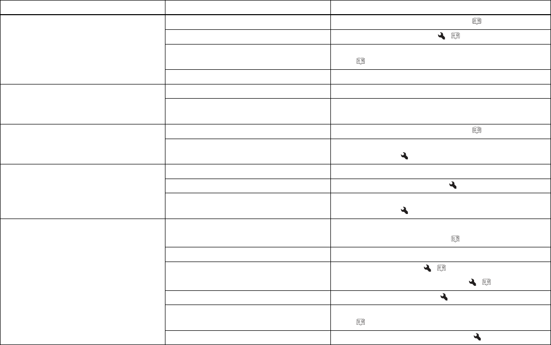
21 TROUBLESHOOTING 167
Faults Possible cause Action
Engine does not crank when the elec-
tric starter button is pressed
Operating error –Carry out the start procedure. ( p. 71)
Battery discharged –Recharge the battery. ( p. 132)
Fuse 1,3,4, or 7is blown –Change the fuses of individual power consumers.
(p. 136)
No ground connection present –Check the ground connection.
Engine turns only if the clutch lever is
drawn
The vehicle is in gear –Shift gear to neutral.
The vehicle is in gear and the side
stand is folded out
–Shift gear to neutral.
Engine turns but does not start Operating error –Carry out the start procedure. ( p. 71)
Fault in fuel injection system –Read out the fault memory using the KTM diag-
nostics tool.
Engine has too little power Air filter is very dirty –Change the air filter.
Fuel filter is very dirty –Check the fuel pressure.
Fault in fuel injection system –Read out the fault memory using the KTM diag-
nostics tool.
Engine overheats Too little coolant in cooling system –Check the cooling system for leakage.
–Check the coolant level. ( p. 146)
Radiator fins very dirty –Clean the radiator fins.
Foam formation in cooling system –Drain the coolant. ( p. 148)
–Fill/bleed the cooling system. ( p. 149)
Thermostat defective –Check the thermostat.
Fuse 5blown –Change the fuses of individual power consumers.
( p. 136)
Defect in radiator fan system –Check the radiator fan system.
21 TROUBLESHOOTING 168
Faults Possible cause Action
Malfunction indicator lamp lights up
yellow
Fault in fuel injection system –Read out the fault memory using the KTM diag-
nostics tool.
Engine dies during the trip Lack of fuel –Refuel. ( p. 81)
Fuse 1,3,4, or 7is blown –Change the fuses of individual power consumers.
(p. 136)
ABS indicator lamp lights up ABS fuse is blown –Change the ABS fuses. ( p. 135)
Large difference in wheel speeds of the
front and rear wheels
–Stop the vehicle, switch off the ignition, and
start it again.
Malfunction in ABS –Read out the ABS fault memory using the KTM
diagnostics tool.
High oil consumption Engine vent hose bent –Route the vent hose without bends or change it if
necessary.
Engine oil level too high –Check the engine oil level. ( p. 156)
Engine oil too thin (low viscosity) –Change the engine oil and oil filter, clean the oil
screen. ( p. 156)
Headlight and parking light are not
functioning
Fuse 6blown –Change the fuses of individual power consumers.
(p. 136)
Turn signal, brake light, and horn are
not functional
Fuse 4or 6blown –Change the fuses of individual power consumers.
(p. 136)
Time is not displayed or not correctly
displayed
Fuse 2is blown –Change the fuses of individual power consumers.
(p. 136)
Battery discharged Ignition was not switched off when
vehicle was parked
–Recharge the battery. ( p. 132)
Battery is not being charged by alter-
nator
–Check the charging voltage.
–Check the open-circuit current.
21 TROUBLESHOOTING 169
Faults Possible cause Action
The combination instrument shows
nothing on the display
Fuse 2is blown –Change the fuses of individual power consumers.
(p. 136)
Speedometer in combination instru-
ment not functioning
Speedometer wiring harness is dam-
aged or plug-in connector is oxidized
–Check the wiring harness and plug-in connector.

22 TECHNICAL DATA 170
22.1 Engine
Design 1-cylinder 4-stroke engine, water-cooled
Displacement 125 cm³ (7.63 cu in)
Stroke 47.2 mm (1.858 in)
Bore 58 mm (2.28 in)
Compression ratio 12.8:1
Control DOHC, 4 valves controlled via cam lever, chain drive
Valve diameter, intake 22.5 mm (0.886 in)
Valve diameter, exhaust 19 mm (0.75 in)
Valve clearance, intake, cold 0.08… 0.12 mm (0.0031… 0.0047 in)
Valve clearance, exhaust, cold 0.13… 0.17 mm (0.0051… 0.0067 in)
Crankshaft bearing Two ball bearings
Conrod bearing Sleeve bearing
Pistons Cast light alloy
Piston rings 1 compression ring, 1 tapered compression piston ring, 1 oil
scraper ring
Engine lubrication Pressure circulation lubrication with one rotary pump
Primary transmission 22:72
Clutch Clutch in oil bath/mechanically activated
Transmission 6-gear, claw shifted
Transmission ratio
1st gear 12:34
2nd gear 15:31
3rd gear 18:28

22 TECHNICAL DATA 171
4th gear 21:26
5th gear 22:23
6th gear 24:22
Mixture preparation Electronically controlled fuel injection
Ignition Contactless controlled fully electronic ignition with digital ignition
adjustment
Alternator 12 V, 230 W
Spark plug BOSCH Super R6 VR 5 NE
Spark plug electrode gap 0.8 mm (0.031 in)
Spark plug BOSCH Super R6 VR 5 NEW
Spark plug electrode gap 1 mm (0.04 in)
Cooling Water cooling, permanent circulation of coolant by water pump
Idle speed 1,450… 1,550 rpm
Starting aid Electric starter
22.2 Engine tightening torques
Oil nozzle M5 6 Nm (4.4 lbf ft) Loctite®243™
Screw, engine vent plate M5 7 Nm (5.2 lbf ft) Loctite®243™
Screw, retaining bracket M5 6 Nm (4.4 lbf ft) Loctite®243™
Screw, retaining bracket, stator cable M5 8 Nm (5.9 lbf ft) Loctite®243™
Screw, stator M5 8 Nm (5.9 lbf ft) Loctite®243™
Clutch cable retaining bracket screw M6 6 Nm (4.4 lbf ft) Loctite®243™
Cylinder head screw M6 12 Nm (8.9 lbf ft) –
Nut, water pump impeller M6 10 Nm (7.4 lbf ft) Loctite®243™

22 TECHNICAL DATA 172
Screw plug, water pump drain hole M6 10 Nm (7.4 lbf ft) –
Screw, alternator cover M6 12 Nm (8.9 lbf ft) –
Screw, bearing retainer M6 12 Nm (8.9 lbf ft) Loctite®243™
Screw, camshaft bearing support M6 10 Nm (7.4 lbf ft) –
Screw, chain securing guide M6 10 Nm (7.4 lbf ft) Loctite®243™
Screw, clutch cover M6 12 Nm (8.9 lbf ft) –
Screw, engine case M6x40 12 Nm (8.9 lbf ft) –
Screw, engine case M6x60 12 Nm (8.9 lbf ft) Loctite®243™
Screw, engine sprocket M6 12 Nm (8.9 lbf ft) –
Screw, freewheel gear retaining bracket M6 12 Nm (8.9 lbf ft) Loctite®243™
Screw, locking lever M6 12 Nm (8.9 lbf ft) Loctite®243™
Screw, oil filter cover M6 12 Nm (8.9 lbf ft) –
Screw, oil pump M6 12 Nm (8.9 lbf ft) Loctite®243™
Screw, retaining bracket, shaft seal ring,
clutch cover
M6 12 Nm (8.9 lbf ft) Loctite®243™
Screw, shift drum locating M6 12 Nm (8.9 lbf ft) Loctite®243™
Screw, starter motor M6 12 Nm (8.9 lbf ft) –
Screw, timing chain tensioner M6 12 Nm (8.9 lbf ft) –
Screw, timing chain tensioning rail M6 12 Nm (8.9 lbf ft) Loctite®243™
Screw, valve cover M6 12 Nm (8.9 lbf ft) –
Screw, water pump cover M6 12 Nm (8.9 lbf ft) –
Nut, conrod bearing M7 24 Nm (17.7 lbf ft) –
Nut, exhaust flange M8 8 Nm (5.9 lbf ft) –
Nut, manifold on cylinder head M8 8 Nm (5.9 lbf ft) –
Screw, balancer shaft gear M8 40 Nm (29.5 lbf ft) Loctite®243™
22 TECHNICAL DATA 173
Screw, camshaft drive sprocket M8 32 Nm (23.6 lbf ft) Loctite®243™
Screw, return spring, quick shifter M8 20 Nm (14.8 lbf ft) Loctite®243™
Stud, exhaust flange M8 22 Nm (16.2 lbf ft) –
Cylinder head screw M10 Step 1
25 Nm (18.4 lbf ft)
Step 2
50 Nm (36.9 lbf ft)
Thread is oiled, head flat is
greased
Oil pressure sensor M10 14 Nm (10.3 lbf ft) –
Rotor screw M10 70 Nm (51.6 lbf ft) Loctite®243™
Water temperature sensor M10 14 Nm (10.3 lbf ft) –
Screw plug, cam lever axis M10x1 10 Nm (7.4 lbf ft) –
Spark plug M12 15 Nm (11.1 lbf ft) –
Nut, inner clutch hub M14LH 60 Nm (44.3 lbf ft) Loctite®243™
Nut, primary gear/timing chain sprocket M14 55 Nm (40.6 lbf ft) Loctite®243™
Oil drain plug M24x1.5 15 Nm (11.1 lbf ft) –
22.3 Capacities
22.3.1 Engine oil
Engine oil 1.5 l (1.6 qt.) External temperature: 0…
50 °C (32… 122 °F)
Engine oil (SAE 15W/50)
(p. 186)
External temperature: −10…
40 °C (14… 104 °F)
Engine oil (SAE 10W/40)
( p. 186)
22.3.2 Coolant
Coolant 1 l (1 qt.) Coolant ( p. 185)
22 TECHNICAL DATA 174
22.3.3 Fuel
Total fuel tank capacity, approx. 13.5 l (3.57 US gal) Super unleaded (ROZ 95/RON 95/PON 91) ( p. 187)
Fuel reserve, approx. 1.5 l (1.6 qt.)
22.4 Chassis
Frame Lattice frame of steel tubes, powder-coated
Fork WP Suspension
Shock absorber WP Suspension
Brake system
Front Disc brake with four-pot brake caliper
Rear Disc brake with single-piston brake caliper, floating
Suspension travel
Front 142 mm (5.59 in)
rear 150 mm (5.91 in)
Brake discs - diameter
Front 300 mm (11.81 in)
Rear 230 mm (9.06 in)
Brake discs - wear limit
Front 4.5 mm (0.177 in)
rear 3.6 mm (0.142 in)
Tire air pressure, solo
Front 2.0 bar (29 psi)
Rear 2.0 bar (29 psi)

22 TECHNICAL DATA 175
Tire air pressure with passenger/full payload
Front 2.0 bar (29 psi)
Rear 2.2 bar (32 psi)
Secondary ratio
Chain 5/8 x 1/4” (520) X-ring
Steering head angle 65°
Wheelbase 1,357±15.5 mm (53.43±0.61 in)
Seat height, unloaded 830 mm (32.68 in)
Ground clearance, unloaded 175 mm (6.89 in)
Dry weight 139 kg (306 lb.)
Maximum permissible front axle load 127 kg (280 lb.)
Maximum permissible rear axle load 228 kg (503 lb.)
Maximum permissible overall weight 355 kg (783 lb.)
22.5 Electrical system
Battery ETZ-9-BS Battery voltage: 12 V
Nominal capacity: 8 Ah
Maintenance-free
Fuse 75011088010 10 A
Fuse 75011088015 15 A
Fuse 90111088025 25 A
Fuse 75011088030 30 A
Headlight LED
Parking light LED
Instrument lights and indicator lamps LED
22 TECHNICAL DATA 176
Turn signal LED
Brake/tail light LED
License plate lamp LED
22.6 Tires
Front tires Rear tires
110/70 R 17 M/C 54H TL
Metzeler Sportec M5 Interact
150/60 R 17 M/C 66H TL
Metzeler Sportec M5 Interact
110/70 R 17 M/C 54H TL
Michelin Pilot Street Radial
150/60 R 17 M/C 66H TL
Michelin Pilot Street Radial
The tires specified represent one of the possible series production tires. Additional information is available in the Service section under:
http://www.ktm.com
22.7 Fork
Fork article number 93001000033
Fork WP Suspension
Fork length 744 mm (29.29 in)
Fork oil 450 ml (15.21 fl. oz.) Fork oil (SAE 5) ( p. 187)
22.8 Shock absorber
Shock absorber article number 93104010044
Shock absorber WP Suspension
Spring preload
Standard 3 clicks

22 TECHNICAL DATA 177
Static sag 14 mm (0.55 in)
Riding sag 49 mm (1.93 in)
Fitted length 304 mm (11.97 in)
22.9 Chassis tightening torques
Screw, chain guard EJOT PT®K60x30 7 Nm (5.2 lbf ft) –
Remaining screws, chassis M4 4 Nm (3 lbf ft) –
Remaining nuts, chassis M5 5 Nm (3.7 lbf ft) –
Remaining screws, chassis M5 5 Nm (3.7 lbf ft) –
Screw, chain guard M5 7 Nm (5.2 lbf ft) Loctite®243™
Screw, compensating tank cap lock, rear
brake
M5 9 Nm (6.6 lbf ft) –
Screw, fuel tank cover M5 4 Nm (3 lbf ft) –
Screw, outer clutch cable guide M5 5 Nm (3.7 lbf ft) –
Screw, side stand switch M5 5 Nm (3.7 lbf ft) Loctite®243™
Screw, tail light M5 5 Nm (3.7 lbf ft) –
Nut, foot brake lever adjustment M6 9 Nm (6.6 lbf ft) –
Remaining nuts, chassis M6 10 Nm (7.4 lbf ft) –
Remaining screws, chassis M6 10 Nm (7.4 lbf ft) –
Screw, ABS hose clamp M6 7 Nm (5.2 lbf ft) –
Screw, ABS module M6 10 Nm (7.4 lbf ft) –
Screw, ABS module retaining bracket on
frame
M6 7 Nm (5.2 lbf ft) –
Screw, air filter box M6 6 Nm (4.4 lbf ft) –
Screw, brake fluid reservoir of rear brake M6 8 Nm (5.9 lbf ft) –

22 TECHNICAL DATA 178
Screw, brake hose clamp M6 7 Nm (5.2 lbf ft) –
Screw, cable holder, side stand switch M6 9 Nm (6.6 lbf ft) Loctite®243™
Screw, chain sliding guard M6 7 Nm (5.2 lbf ft) –
Screw, combination instrument M6 7 Nm (5.2 lbf ft) –
Screw, compensating tank M6 5 Nm (3.7 lbf ft) –
Screw, damper block M6 8 Nm (5.9 lbf ft) –
Screw, engine sprocket cover M6 8 Nm (5.9 lbf ft) –
Screw, foot brake cylinder M6 9 Nm (6.6 lbf ft) Loctite®243™
Screw, front fender M6 7 Nm (5.2 lbf ft) –
Screw, front seat fixing M6 6 Nm (4.4 lbf ft) –
Screw, front spoiler front M6x13 9 Nm (6.6 lbf ft) –
Screw, front spoiler rear M6x9 9 Nm (6.6 lbf ft) –
Screw, fuel pump M6 10 Nm (7.4 lbf ft) –
Screw, headlight M6 8 Nm (5.9 lbf ft) –
Screw, ignition coil M6 8 Nm (5.9 lbf ft) –
Screw, ignition lock (tamper-proof
screw)
M6 13 Nm (9.6 lbf ft) –
Screw, license plate holder M6 12 Nm (8.9 lbf ft) Loctite®243™
Screw, lower rear panel M6 7 Nm (5.2 lbf ft) –
Screw, magnetic holder on side stand M6 5 Nm (3.7 lbf ft) Loctite®243™
Screw, main silencer M6 12 Nm (8.9 lbf ft) –
Screw, main silencer retaining bracket M6 9 Nm (6.6 lbf ft) –
Screw, radiator holder M6 10 Nm (7.4 lbf ft) –
Screw, radiator shield M6 7 Nm (5.2 lbf ft) –
Screw, rear ABS sensor wheel M6 8 Nm (5.9 lbf ft) Loctite®243™

22 TECHNICAL DATA 179
Screw, rear splash protector M6 9 Nm (6.6 lbf ft) –
Screw, rollover sensor M6 8 Nm (5.9 lbf ft) –
Screw, shift lever linkage M6 11 Nm (8.1 lbf ft) Loctite®243™
Screw, wheel speed sensor holder M6 8 Nm (5.9 lbf ft) –
Nut, rear sprocket M8 27 Nm (19.9 lbf ft) Loctite®243™
Remaining nuts, chassis M8 25 Nm (18.4 lbf ft) –
Remaining screws, chassis M8 25 Nm (18.4 lbf ft) –
Screw, bottom triple clamp M8 12 Nm (8.9 lbf ft) –
Screw, engine bearer M8 22 Nm (16.2 lbf ft) –
Screw, foot brake lever M8 16 Nm (11.8 lbf ft) Loctite®243™
Screw, fork stub M8 15 Nm (11.1 lbf ft) –
Screw, front brake caliper M8 30 Nm (22.1 lbf ft) Loctite®204™
Screw, front brake disc M8 30 Nm (22.1 lbf ft) Loctite®243™
Screw, front seat fixing M8 20 Nm (14.8 lbf ft) –
Screw, front wheel spindle M8 25 Nm (18.4 lbf ft) –
Screw, fuel tank M8 20 Nm (14.8 lbf ft) –
Screw, grab handle M8 22 Nm (16.2 lbf ft) –
Screw, handlebar clamp M8 20 Nm (14.8 lbf ft) Loctite®243™
Screw, horn M8 12 Nm (8.9 lbf ft) –
Screw, lower rear panel M8 15 Nm (11.1 lbf ft) Loctite®243™
Screw, main silencer M8 23 Nm (17 lbf ft) –
Screw, passenger footrest bracket M8 22 Nm (16.2 lbf ft) Loctite®243™
Screw, rear brake disc M8 21 Nm (15.5 lbf ft) Loctite®243™
Screw, rear frame M8 25 Nm (18.4 lbf ft) Loctite®243™
Screw, rear seat fixing M8 18 Nm (13.3 lbf ft) –

22 TECHNICAL DATA 180
Screw, seat support plate M8 18 Nm (13.3 lbf ft) –
Screw, top triple clamp M8 15 Nm (11.1 lbf ft) –
Banjo bolt, brake line M10 24 Nm (17.7 lbf ft) –
Fitting side stand M10 35 Nm (25.8 lbf ft) Loctite®243™
Nut mirror image left M10 16 Nm (11.8 lbf ft) –
Remaining nuts, chassis M10 45 Nm (33.2 lbf ft) –
Remaining screws, chassis M10 45 Nm (33.2 lbf ft) –
Screw, engine bearer M10 49 Nm (36.1 lbf ft) –
Fitting, handlebar support M10x1.25 20 Nm (14.8 lbf ft) –
Fitting, shock absorber, bottom M10x1.25 51 Nm (37.6 lbf ft) Loctite®243™
Nut, mirror, right M10LHx1.25 16 Nm (11.8 lbf ft) –
Screw, combination instrument bracket M10x1.25 21 Nm (15.5 lbf ft) –
Screw, front footrest bracket M10x1.25 44 Nm (32.5 lbf ft) –
Screw, front footrest bracket / engine
bearer
M10x1.25 49 Nm (36.1 lbf ft) –
Screw, side stand bracket M10x1.25 25 Nm (18.4 lbf ft) Loctite®243™
Screw, top shock absorber M10x1.25 51 Nm (37.6 lbf ft) Loctite®243™
Stud, rear sprocket M10x1.25 50 Nm (36.9 lbf ft) –
Nut, rear wheel spindle M14x1.5 98 Nm (72.3 lbf ft) –
Nut, swingarm pivot M14x1.5 98 Nm (72.3 lbf ft) –
Screw, steering head, top M16x1.5 49 Nm (36.1 lbf ft) Loctite®243™
Lambda sensor M18x1.5 19 Nm (14 lbf ft) –
Swingarm bearing adjusting ring M22x1 Tighten and ensure that there
is no play
–

22 TECHNICAL DATA 181
Nut, steering head M30x1 1st stage
45 Nm (33.2 lbf ft)
2nd stage (loosen, counter-
clockwise)
2 turns
3rd stage
5 Nm (3.7 lbf ft)
–

23 DECLARATIONS OF CONFORMITY 182
23.1 EU declaration of conformity
Info
The functional and equipment scope is model-dependent and may not include all wireless systems referred to.
COBO SpAhereby declares that the BT‑ROUTER wireless system conforms with the relevant guidelines. The full text of the EU Declaration of
Conformity is available at the following Internet address.
Certification website: http://www.ktm.com/btrouter
JNS Instruments Ltd.hereby declares that 210M1100 wireless system conforms with the relevant guideline. The full text of the EU Declara-
tion of Conformity is available at the following Internet address.
Certification website: http://www.ktm.com/210m1100
KTM AGhereby declares that the KTM RACE ON system wireless system conforms with the relevant guidelines. The full text of the EU Decla-
ration of Conformity is available at the following Internet address.
Certification website: http://www.ktm.com/ktm-race-on-system
KTM AGhereby declares that the LC8 DASHBOARD wireless system conforms with the relevant guidelines. The full text of the EU Declaration
of Conformity is available at the following Internet address.
Certification website: http://www.ktm.com/lc8-dashboard
Schrader Electronics Ltdhereby declares that Tyre Pressure Monitoring Sensor "BC5A4" wireless system conforms with the relevant guideline.
The full text of the EU Declaration of Conformity is available at the following Internet address.
Certification website: http://www.ktm.com/tpms
Schrader Electronics Ltdhereby declares that Tyre Pressure Monitoring Sensor "RDC3" wireless system conforms with the relevant guideline.
The full text of the EU Declaration of Conformity is available at the following Internet address.
Certification website: http://www.ktm.com/tpms

23 DECLARATIONS OF CONFORMITY 183
23.2 FCC declaration of conformity
Info
The functional and equipment scope is model-dependent and may not include all wireless systems referred to.
210M1100
FCC ID: 2AKR7‑210M1100
IC: 22291‑210M1100
BT‑ROUTER
FCC ID: Z64‑2564N
IC: 451I‑2564N
KTM RACE ON system ‑Active Key
FCC ID: VFZKLGKZADI01
IC: 22239-KLGKZADI01
KTM RACE ON system ‑Main Unit
FCC ID: VFZKLGMZADI01
IC: 22239-KLGMZADI01
LC8 DASHBOARD
FCC ID: 2AKP9-LC8CLUSTER1
IC: 22273-LC8CLUSTER1
Tyre Pressure Monitoring Sensor "BC5A4"
FCC ID: MRXBC5A4
IC: 2546A-BC5A4
Tyre Pressure Monitoring Sensor "RDC3"
FCC ID: MRXRDC3
IC: 2546A-RDC3
Warning
This device complies with article 15 of the FCC regulations.
Operation is subject to the following two conditions:
23 DECLARATIONS OF CONFORMITY 184
1 This device must not cause harmful interference.
2 This device must be able to absorb any received interference, including interference that potentially causes undesirable operation.
This equipment has been tested and complies with the limits for Class B digital devices, in accordance with article 15 of the FCC regu-
lations. These limits are designed to provide satisfactory protection against harmful interference in residential areas. Devices of this type
generate and use and also transmit radio frequencies. Therefore, if they are not installed and operated in accordance with the instructions,
they may cause harmful interference to radio reception. However, there is no guarantee that interference will not occur in certain cases of
application. Should this device cause harmful interference to radio or television reception, (check this by switching the device on and off),
you can potentially eliminate this interference as follows:
–Re-align the receiving antenna.
–Increase the distance between device and radio receiver.
–Connect the device and the radio receiver to separate electric circuits.
–Consult your dealer or a radio/TV technician.
Alterations and modifications not expressly approved by the relevant authority may result in the user being prohibited from operating the
equipment.

24 SUBSTANCES 185
Brake fluid DOT 4 / DOT 5.1
Standard/classification
–DOT
Guideline
–Use only brake fluid that complies with the specified standard (see specifications on the container) and that exhibits the corresponding
properties.
Recommended supplier
Castrol
–REACT PERFORMANCE DOT 4
Motorex®
–Brake Fluid DOT 5.1
Coolant
Guideline
–Only use high-grade, silicate-free coolant with corrosion inhibitor additive for aluminum motors. Low grade and unsuitable antifreeze
causes corrosion, deposits and frothing.
–Do not use pure water as only coolant is able to meet the requirements needed in terms of corrosion protection and lubrication proper-
ties.
–Only use coolant that complies with the requirements stated (see specifications on the container) and that has the relevant properties.
Antifreeze protection to at least −25 °C (−13 °F)
The mixture ratio must be adjusted to the necessary antifreeze protection. Use distilled water if the coolant needs to be diluted.
The use of premixed coolant is recommended.
24 SUBSTANCES 186
Observe the coolant manufacturer specifications for antifreeze protection, dilution and miscibility (compatibility) with other coolants.
Recommended supplier
Motorex®
–COOLANT M3.0
Engine oil (SAE 15W/50)
Standard/classification
–JASO T903 MA ( p. 190)
–SAE ( p. 190) (SAE 15W/50)
Guideline
–Use only engine oils that comply with the specified standards (see specifications on the container) and that possess the corresponding
properties.
Partially synthetic engine oil
Recommended supplier
Motorex®
–Formula 4T
Engine oil (SAE 10W/40)
Standard/classification
–JASO T903 MA ( p. 190)
–SAE ( p. 190) (SAE 10W/40)
Guideline
–Use only engine oils that comply with the specified standards (see specifications on the container) and that possess the corresponding
properties.
Partially synthetic engine oil
24 SUBSTANCES 187
Recommended supplier
Motorex®
–Formula 4T
Fork oil (SAE 5)
Standard/classification
–SAE ( p. 190) (SAE 5)
Guideline
–Use only oils that comply with the specified standards (see specifications on the container) and that possess the corresponding proper-
ties.
Recommended supplier
Motorex®
–Racing Fork Oil
Super unleaded (ROZ 95/RON 95/PON 91)
Standard/classification
–DIN EN 228 (ROZ 95/RON 95/PON 91)
Guideline
–Only use unleaded super fuel that matches or is equivalent to the specified fuel grade.
–Fuel with an ethanol content of up to 10 % (E10 fuel) is safe to use.
Info
Do not use fuel containing methanol (e. g. M15, M85, M100) or more than 10 % ethanol (e. g. E15, E25, E85, E100).

25 AUXILIARY SUBSTANCES 188
Chain cleaner
Recommended supplier
Motorex®
–Chain Clean
Chain lube for road use
Guideline
Recommended supplier
Motorex®
–Chainlube Road
Fuel additive
Recommended supplier
Motorex®
–Fuel Stabilizer
Long-life grease
Recommended supplier
Motorex®
–Bike Grease 2000
Motorcycle cleaner
Recommended supplier
Motorex®
–Moto Clean

25 AUXILIARY SUBSTANCES 189
Perfect Finish and high gloss polish for paints
Recommended supplier
Motorex®
–Moto Polish & Shine
Preserving materials for paints, metal and rubber
Recommended supplier
Motorex®
–Moto Protect
Special cleaner for glossy and matte paint finishes, metal and plastic surfaces
Recommended supplier
Motorex®
–Quick Cleaner
Universal oil spray
Recommended supplier
Motorex®
–Joker 440 Synthetic

26 STANDARDS 190
JASO T903 MA
Different technical development directions required a separate specification for 4-stroke motorcycles –the JASO T903 MA standard.
Earlier, engine oils from the automobile industry were used for 4-stroke motorcycles because there was no separate motorcycle specifica-
tion.
Whereas long service intervals are demanded for automobile engines, the focus for motorcycle engines is on high performance at high
engine speeds.
In most motorcycle engines, the transmission and the clutch are lubricated with the same oil.
The JASO MA standard meets these special requirements.
SAE
The SAE viscosity classes were defined by the Society of Automotive Engineers and are used for classifying oils according to their viscos-
ity. The viscosity describes only one property of oil and says nothing about quality.

27 INDEX OF SPECIAL TERMS 191
ABS ABS Safety system that prevents locking of the wheels when driving
straight ahead without the influence of lateral forces
DRL Daytime Running Light Light, which enhances the visibility of the vehicle during the day
but is not focused, and in contrast to low beam does not illuminate
the road surface
KTM MY RIDE System for wireless communication with appropriate cellphones
and headsets for telephony and audio
OBD On-board diagnosis Vehicle system that monitors emission- and safety-related values

28 LIST OF ABBREVIATIONS 192
Art. no. Article number
ca. circa
cf. compare
e.g. for example
etc. et cetera
i.a. inter alia
no. number
poss. possibly
29 LIST OF SYMBOLS 193
29.1 Red symbols
Red symbols indicate an error condition that requires immediate intervention.
The oil pressure warning lamp lights up red –The oil pressure is too low.
29.2 Yellow and orange symbols
Yellow and orange symbols indicate an error condition that requires prompt intervention. Active driving aids are also represented by yellow
or orange symbols.
Malfunction indicator lamp lights up yellow –The OBD has detected an emission- or safety-critical fault.
ABS indicator lamp lights up yellow –Status or error messages relating to ABS.
The general warning lamp lights up yellow –An operating safety (warning) message was detected. This is also
shown on the display.
29.3 Green and blue symbols
Green and blue symbols reflect information.
The turn signal indicator lamp flashes green simultaneously with the turn signal –The turn signal is switched on.
The idle indicator lamp lights up green –The transmission is in idle.
The high beam indicator lamp lights up blue –The high beam is switched on.

INDEX 194
INDEX
A
ABS ........................................104
ABS fuses
changing ..................................135
Accessories ....................................14
Antifreeze
checking ..................................144
Antilock brake system ............................104
Applying the brakes ...............................76
Auxiliary substances ..............................14
B
Baggage ......................................68
Battery
installing ..................................131
recharging .................................132
removing ..................................130
Brake discs
checking ..................................105
Brake fluid
frontbrake,adding ...........................107
rearbrake,adding ...........................113
Brake fluid level
frontbrake,checking .........................106
rearbrake,checking ..........................112
Brake linings
frontbrake,checking .........................109
rearbrake,checking ..........................116
Brakes .......................................76
C
Capacity
coolant ...................................173
engine oil . . . . . . . . . . . . . . . . . . . . . . . . . . . . . 159, 173
fuel . . . . . . . . . . . . . . . . . . . . . . . . . . . . . . . . . . 82, 174
Chain
chain dirt accumulation, checking . . . . . . . . . . . . . . . . . 94
checking ...................................99
cleaning ...................................95
Chain tension
adjusting ...................................97
checking ...................................96
Chassis number .................................20
Clutch lever ....................................22
Clutch lever play
checking ..................................153
Combination instrument . . . . . . . . . . . . . . . . . . . . . . . . . 35-65
ABS ......................................56
activationandtest ............................35
Audio .....................................52
Bluetooth ...................................58
coolant temperature indicator . . . . . . . . . . . . . . . . . . . . . 45
day-nightmode ..............................36

INDEX 195
display ....................................40
Distance ...................................62
DRL .......................................61
Extra Functions ...............................65
Favourites ..................................57
Favourites display .............................46
fuelleveldisplay .............................45
Fuel Cons ...................................63
General Info .................................54
indicatorlamps ..............................38
Info .......................................49
KTM MY RIDE ................................48
Language ...................................64
menu .....................................48
Motorcycle ..................................49
ODO display .................................44
overview ...................................35
Pairing ....................................51
Preferences .................................50
Quick Selector 1 ..............................57
Quick Selector 1 display .........................47
Quick Selector 2 ..............................58
Quick Selector 2 display .........................47
Service ....................................64
Settings ....................................50
shiftwarninglight .............................43
speed ..................................42,44
telephony ..................................53
Temp .....................................63
time ......................................46
Trip 1 .....................................54
Trip 2 .....................................55
Warning ....................................55
warningnotes ...............................37
Combinationswitch.............................. 23
overview ...................................23
Coolant
draining ..................................148
Coolant level
checking . . . . . . . . . . . . . . . . . . . . . . . . . . . . . . 144, 146
Coolingsystem................................ 142
filling/bleeding . . . . . . . . . . . . . . . . . . . . . . . . . . . . . . 149
Customer service ................................15
D
Declarations of conformity . . . . . . . . . . . . . . . . . . . . . 182-184
EU ......................................182
FCC .....................................183
Diagnostics connector ............................141
E
Electric starter button .............................26
Emergency OFF switch .............................26
Engine
runningin ..................................67
Engine number ..................................21

INDEX 196
Engine oil
adding ...................................159
changing ..................................156
Engine oil level
checking ..................................156
Engine sprocket
checking ...................................99
Environment ....................................12
F
Figures .......................................15
Filler cap
closing ....................................30
opening ....................................28
Filling up
fuel ......................................81
Footbrakelever................................ 33
freetravel,adjusting ..........................111
freetravel,checking ..........................110
Fork legs
dustboots,cleaning ...........................91
Front rider's seat
mounting ..................................94
removing ...................................93
Front spoiler
installing ..................................103
removing ..................................102
Front wheel
installing ..................................118
removing ..................................117
Fuse
individual power consumers, changing . . . . . . . . . . . . . . 136
G
Grab handles ...................................31
H
Hand brake lever ................................22
Headlight
daytimerunninglight .........................129
range,adjusting .............................139
Headlight adjustment
checking ..................................139
Horn button ....................................25
I
Ignition lock ...................................27
Implied warranty .................................14
Indicator lamps .................................38
K
Key number ....................................21
L
Light switch ....................................24
Loading the vehicle ...............................68

INDEX 197
M
Misuse ........................................9
Motorcycle
cleaning ..................................161
lifting with front lifting gear . . . . . . . . . . . . . . . . . . . . . . 89
raising with the rear lifting gear . . . . . . . . . . . . . . . . . . . 88
removing the rear from the lifting gear . . . . . . . . . . . . . . . 88
taking from the front lifting gear . . . . . . . . . . . . . . . . . . . 90
O
Oil filter
changing ..................................156
Oil screen
cleaning ..................................156
Operating substances ..............................14
Owner's Manual .................................13
P
Parking ......................................78
Passenger footrests ...............................32
Passenger seat
mounting ..................................93
removing ...................................92
Play in the clutch lever
adjusting ..................................155
Play in throttle cable
adjusting ..................................153
Preparing for use
adviceonfirstuse ............................66
afterstorage ...............................166
checks and maintenance when preparing for use . . . . . . . . 70
Protective clothing ...............................12
R
Rear hub rubber dampers
checking ..................................124
Rear sprocket
checking ...................................99
Rear wheel
installing ..................................121
removing ..................................120
Riding ...................................... 73
startingoff .................................73
S
Safe operation ..................................11
Seat lock .....................................30
Service .......................................15
Service schedule ............................. 83-85
Shiftlever.................................... 32
adjusting ...................................87
Shifting ......................................73
Shock absorber
spring pretension, adjusting . . . . . . . . . . . . . . . . . . . . . . 86
Side stand .....................................34

INDEX 198
Spare parts ....................................14
Starting ......................................71
Steering
locking ....................................27
unlocking ..................................28
Steering lock ...................................27
Stopping ......................................78
Storage .....................................165
Switch
on the left side of the handlebar . . . . . . . . . . . . . . . . . . . 23
on the right side of the handlebar . . . . . . . . . . . . . . . . . . 26
T
Technical data
capacities .................................173
chassis ...................................174
chassis tightening torques . . . . . . . . . . . . . . . . . . . . . . 177
electricalsystem ............................175
engine ...................................170
engine tightening torques . . . . . . . . . . . . . . . . . . . . . . 171
fork .....................................176
shockabsorber ..............................176
tires .....................................176
Throttle cable play
checking ..................................152
Throttle grip ....................................23
Time
adjusting ...................................60
Tire air pressure
checking ..................................127
Tire condition
checking ..................................125
Tool set ......................................31
Transport .....................................80
Troubleshooting ............................ 167-169
Turn signal switch ................................25
Type label .....................................20
U
USB diagnostics plug .............................141
Use definition ...................................9
V
View of vehicle
frontleft ...................................16
rearright ...................................18
W
Warranty ......................................14
Winter operation
checks and maintenance steps . . . . . . . . . . . . . . . . . . . 163
Work rules ....................................12

*3213561en*
3213561en
02/2017
KTM Sportmotorcycle GmbH
5230 Mattighofen/Austria
http://www.ktm.com
Photo: Mitterbauer/KTM

FCC/ISED Regulatory notices
Modification statement
Changes or modifications not expressly approved by the party responsible for compliance could void the user’s
authority to operate the equipment.
Les changements ou modifications non expressément approuvés par la partie responsable de la conformité
pourraient annuler l'autorisation de l'utilisateur d'utiliser l'équipement.
Interference statement
This device complies with Part 15 of the FCC Rules and Industry Canada’s licence-exempt RSS standards.
Operation is subject to the following two conditions: (1) this device may not cause interference, and (2) this
device must accept any interference, including interference that may cause undesired operation of the device.
Le présent appareil est conforme aux CNR d'Industrie Canada applicables aux appareils radio exempts de licence.
L'exploitation est autorisée aux deux conditions suivantes : (1) l'appareil ne doit pas produire de brouillage, et (2)
l'utilisateur de l'appareil doit accepter tout brouillage radioélectrique subi, même si le brouillage est susceptible
d'en compromettre le fonctionnement.
Wireless notice
This device complies with FCC and ISED radiation exposure limits set forth for an uncontrolled environment and
meets the FCC radio frequency (RF) Exposure Guidelines. This transmitter must not be co-located or operating in
conjunction with any other antenna or transmitter.
Cet appareil est conforme aux limites d'exposition aux rayonnements de l’ISDE pour un environnement non
contrôlé. L'émetteur ne doit pas être colocalisé ni fonctionner conjointement avec à autre antenne ou autre
émetteur.
Interference statement
This device complies with Part 15 of the FCC Rules and Industry Canada’s licence-exempt RSS standards.
Operation is subject to the following two conditions: (1) this device may not cause interference, and (2) this
device must accept any interference, including interference that may cause undesired operation of the device.
Le présent appareil est conforme aux CNR d'Industrie Canada applicables aux appareils radio exempts de licence.
L'exploitation est autorisée aux deux conditions suivantes : (1) l'appareil ne doit pas produire de brouillage, et (2)
l'utilisateur de l'appareil doit accepter tout brouillage radioélectrique subi, même si le brouillage est susceptible
d'en compromettre le fonctionnement.
FCC Class B digital device notice
This equipment has been tested and found to comply with the limits for a Class B digital device, pursuant to part
15 of the FCC Rules. These limits are designed to provide reasonable protection against harmful interference in a
residential installation. This equipment generates uses and can radiate radio frequency energy and, if not installed
and used in accordance with the instructions, may cause harmful interference to radio communications. However,
there is no guarantee that interference will not occur in a particular installation. If this equipment does cause
harmful interference to radio or television reception, which can be determined by turning the equipment off and
on, the user is encouraged to try to correct the interference by one or more of the following measures:
-Reorient or relocate the receiving antenna.
- Increase the separation between the equipment and receiver.
- Connect the equipment into an outlet on a circuit different from that to which the receiver is connected.
-Consult the dealer or an experienced radio/TV technician for help.
CAN ICES-3 (B) / NMB-3 (B)
This Class B digital apparatus complies with Canadian ICES-003.
Cet appareil numérique de classe B est conforme à la norme canadienne NMB-003.
Model: 210-M1100
FCC ID: 2AKR7-210M1100
IC: 22291-210M1100