OTC Wireless 0207232XG 2.4GHz Transceiver Radio With RS232 Interface User Manual 2
OTC Wireless Inc 2.4GHz Transceiver Radio With RS232 Interface 2
UserManual.wiki
>
OTC Wireless
>
0207232XG User Manual
User Manual
Navigation menu
Upload a User Manual
Namespaces
Wiki Guide
HTML
PDF
Info
Views
User Manual
Discussion / Help
Navigation
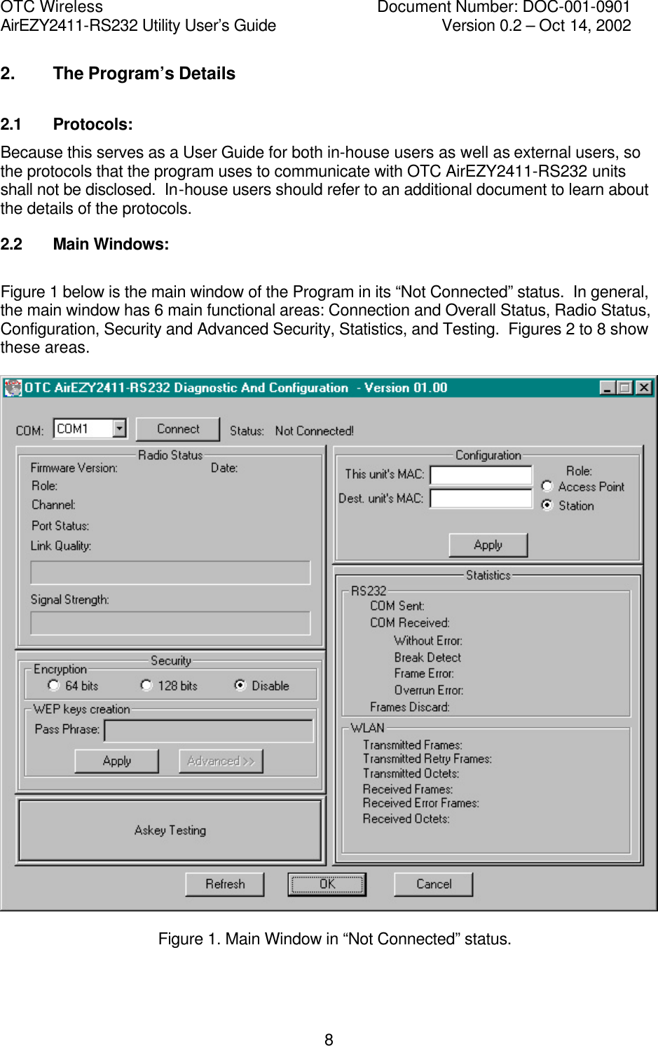
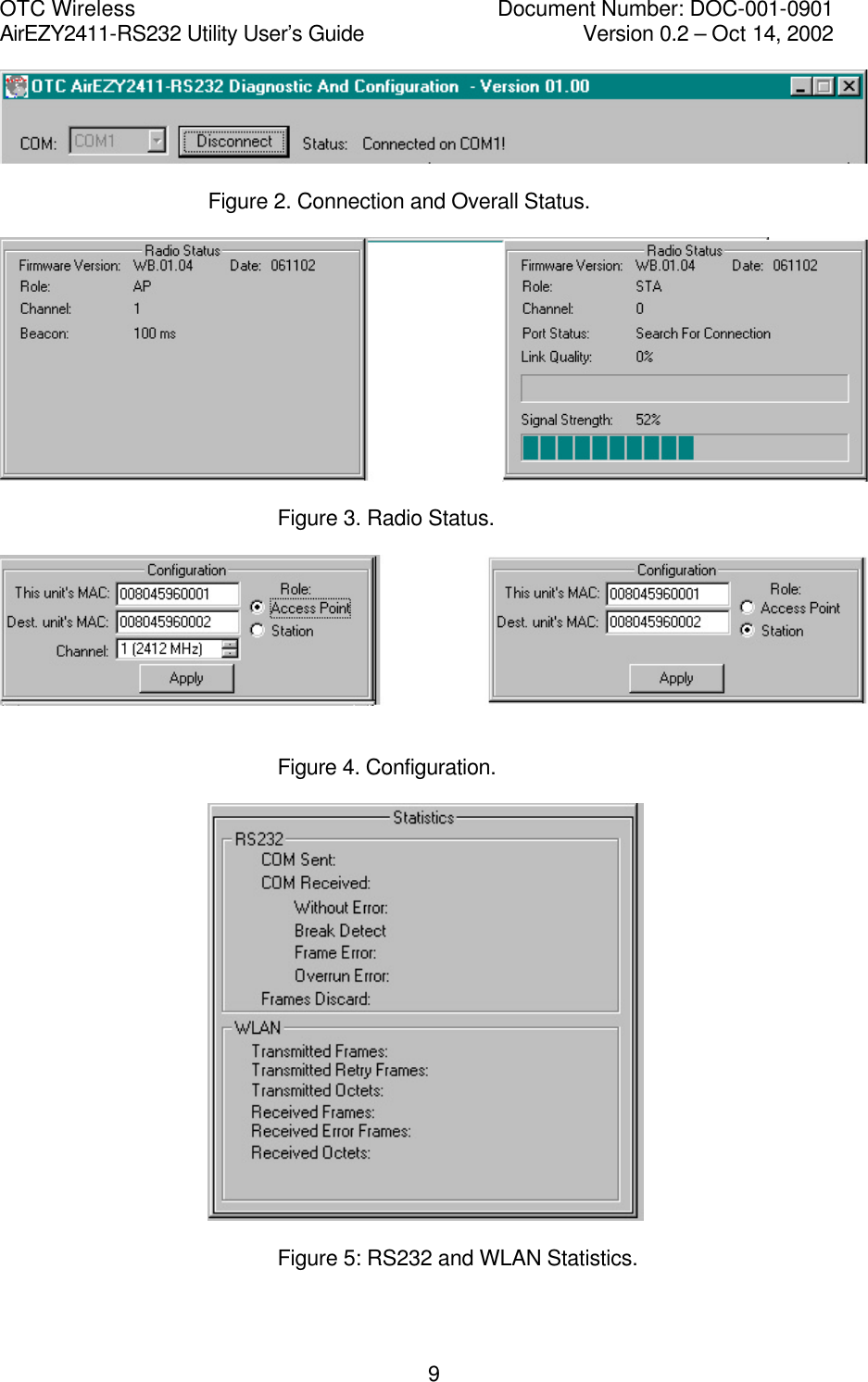
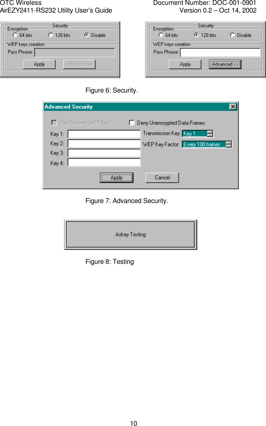

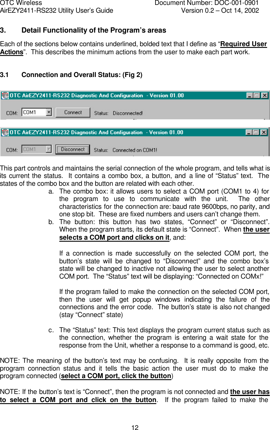
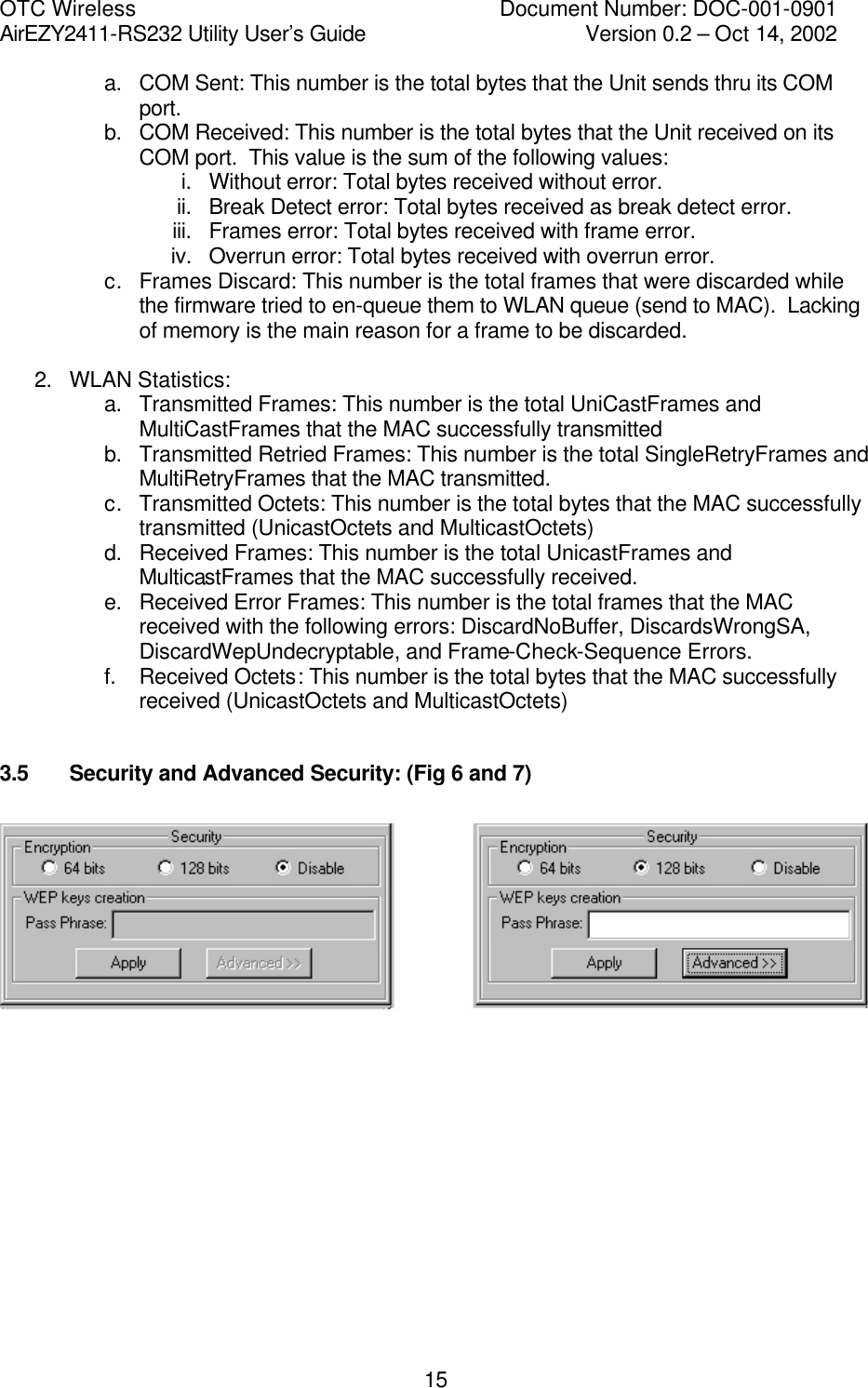
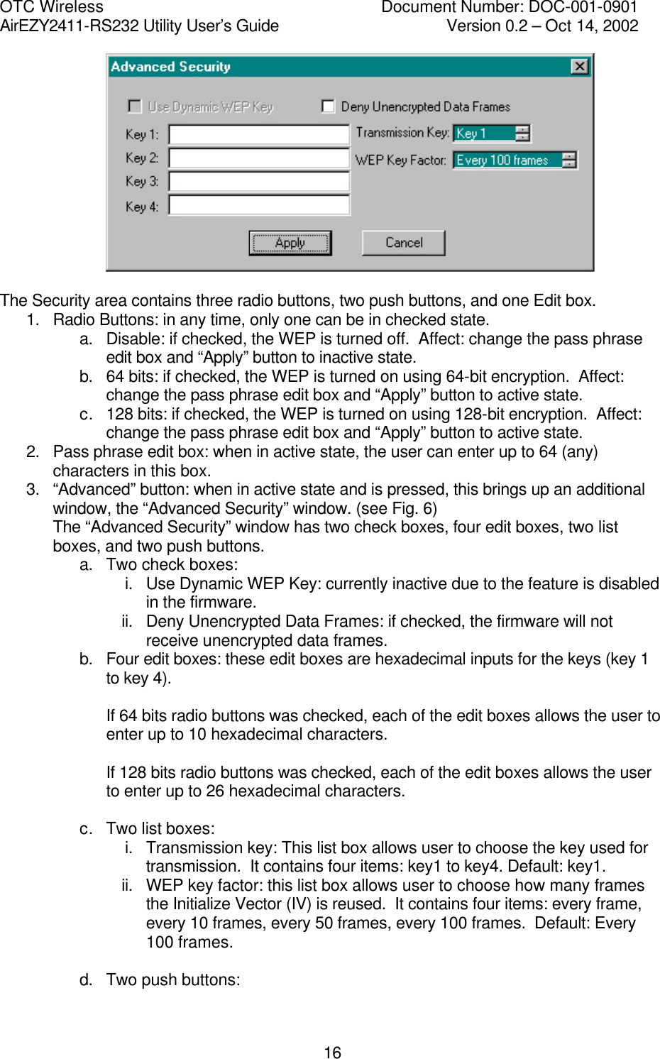
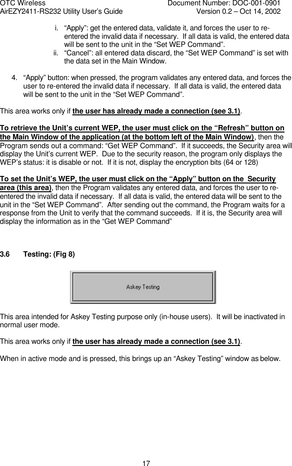
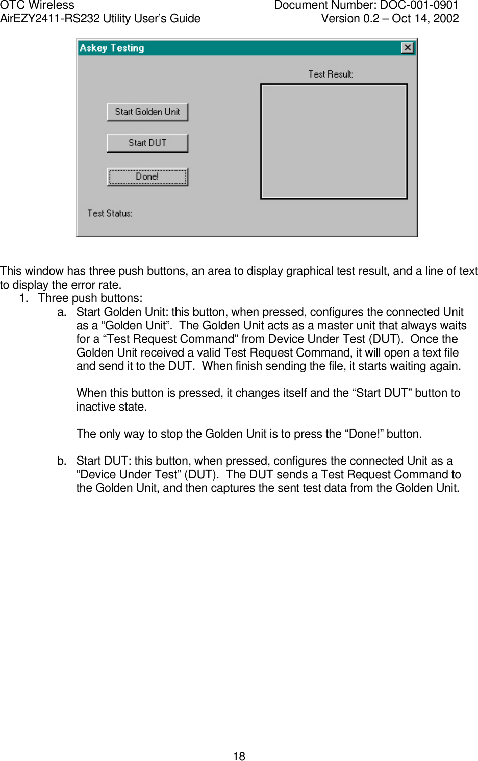
![OTC Wireless Document Number: DOC-001-0901 AirEZY2411-RS232 Utility User’s Guide Version 0.2 – Oct 14, 2002 14Program sends out a “Get Configuration Command” and if it succeeds, the Configuration area will display the Unit’s configuration: a. This unit’s MAC: b. Dest. Unit’s MAC: These are 6-byte hexadecimal numbers (must be 12 hexadecimal numbers [0-9, a-f, A-F] on each of the fields). c. This Unit’s Role: Station or Access Point. d. If the Unit is an Access Point, a list-box channel is shown and it displays the current channel of the Access Point. To set the Unit’s Configuration, the user must click on the “Apply” button on the Configuration area (this area), then the Program will capture this unit’s MAC, destination unit’s MAC, the selected role, and the channel if the role is “Access Point”. The Program then validates the values, requires the user to re-enter any invalid values, and sends out a “Set Configuration Command”. After sending out the command, the Program waits for a response from the Unit to verify the command succeeds. If it is, the Configuration area will display the information as in the “Get Configuration Command” 3.4 RS232 and WLAN Statistics: (Fig 5) First, the user has to make a connection (see 3.1) To retrieve the Unit’s Statistics, the user must click on the “Refresh” button on the Main Window of the application (at the bottom left of the Main Window), then the Program sends out two commands: “Get RS232 Statistics Command” and “Get WLAN Statistics Command”. If they succeed, the Statistics area will display the Unit’s RS232 and WLAN Statistics: 1. RS232 Statistics:](https://usermanual.wiki/OTC-Wireless/0207232XG/User-Guide-276622-Page-14.png)