Ogemray Technology GWF-5M01 Wireless Network Card User Manual 5M01 product datasheet V1 5x
Shenzhen Ogemray Technology Co.,Ltd Wireless Network Card 5M01 product datasheet V1 5x
Manual
1 / 14
All rights reserved
All information contained in this sheet may not be changed without permission
PRODUCT MODULE: GWF-5M01
VERSION: V1.5
DATE: 2015-11-18
I
IE
EE
EE
E
8
80
02
2.
.1
11
1
a
a/
/b
b/
/g
g/
/n
n/
/a
ac
c5
5.
.8
8G
G/
/2
2.
.4
4G
GH
Hz
z
4
43
33
3M
Mb
bp
ps
s/
/1
15
50
0M
Mb
bp
ps
s
P
P
PR
R
RO
O
OD
D
DU
U
UC
C
CT
T
T
D
D
DA
A
AT
T
TA
A
AS
S
SH
H
HE
E
EE
E
ET
T
T
2 / 14
※※V
VE
ER
RS
SI
IO
ON
N
H
HI
IS
ST
TO
OR
RY
Y(
(C
CO
ON
NT
TA
AI
IN
NE
ED
D
C
CH
HA
AN
NG
GE
E
L
LO
OG
GS
S)
) ※ ※
VERSION CHANGE LOGS WRITTEN BY VERIFIED BY DATE DEPARTMENT
V1.0 First version Yanglu Liujun 2015.08.28 RD
V1.5 PCB Update Yanglu Liujun 2015.11.18 RD
3 / 14
C
CO
ON
NT
TE
EN
NT
TS
S
1.Product Basic Information 4
1.1 Product Introduction 4
1.2 Product Features 5
2 Product Basic Function 6
2.1 Brief Specification 6
2.2 Hardware Information 6
2.3 Software Information 8
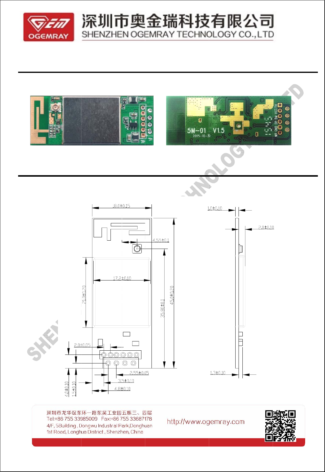
2.4 Mechanical Information 9
2.4.1 Product Appearance 9
2.4.2 Product Dimension 9
2.4.3 RF Signal Input and Output 10
3. Agency Approval 11
4.Environment Requirements 12
4.1 Suitable Temperature 12
4.2 Suitable Humidity 12
5. Available WLAN Channels in Major Countries 12
6. Disclaimer 14
4 / 14
1
1.
.P
Pr
ro
od
du
uc
ct
t
B
Ba
as
si
ic
c
I
In
nf
fo
or
rm
ma
at
ti
io
on
n
1
1.
.1
1P
Pr
ro
od
du
uc
ct
t
I
In
nt
tr
ro
od
du
uc
ct
ti
io
on
n
The GWF-5M01 is a WLAN PCB module with4/6-pin connector supporting USB2.0/1.1 interface, it uses
the latest 802.11ac technology and being compliant with IEEE 802.11a/b/g/n/ac specification, offering
feature-rich wireless connectivity and reliable throughput from an extended distance. Optimized RF
architecture and baseband algorithms provide superb performance and low power consumption.MT7610UN
integrates MAC design deploys a high efficient DMA engine and hardware data processing accelerators
which offloads the host processor.
The MT7610UN is designed to support standard based features in the areas of security, quality of
service and international regulations, giving end users the greatest performance any time and in
any circumstance.
This module operates in 2.4GHz and 5GHz ISM frequency band with low power consumption; it
applies a highly integrated MAC/BBP and RF single chip MT7610UN with 433Mbps PHY rate supporting.
The small form factor and low cost design provide excellent performance for the wireless connectivity, it is
ideal for confine space application.
It has a built-in aerial, or an I-PEX receptacle, and operates in dual-frequency, to let users have the
chance to choose the faster network environment. This module also supports several encryption patterns, to
let users to enjoy fast network speed and clean safe network environment.
GWF-5M01 belongs to the kind of broadband network module, the bandwidth can reach to 80MHz. It
prevents the traffic jam and shorten the time delay in network, and it can operates as a mate of many devices,
such as IP camera, IP STB, TV, Internet broadcasting equipment.
It is compatible with many kinds of operation system, for example, Windows Vista, XP/7/8/2000, Linux,
Mac etc to avoid the problem of OS incompatibility.
5 / 14
1
1.
.2
2
P
Pr
ro
od
du
uc
ct
t
F
Fe
ea
at
tu
ur
re
es
s
Built in antenna or external antenna
Support WPS, Wi-Fi direct
802.11a: 6,9,12,18,24,36,48,54Mbps
802.11b: 1, 2,5.5,11Mbps
802.11g: 6, 9,12,18, 24,36,48,54Mbps
802.11n: (20MHz)MCS0-7, up to 72Mbps, (40MHz)MCS0-7, up to 150Mbps
802.11ac: up to 433Mbps(80MHz)
Support safe encryption pattern, such as WFA,WPA, WPA2, Personal, WPS2.0, WAPI
Built-in power consumption management function
USB2.0/1.1 interface
Excellent anti-interference ability
Compatible with many kinds of operation system, for example, Windows Vista, XP/7/8/2000, Linux,
and Mac etc.
NOTICE: WLAN communication channel is the communication channel used for IEEE
802.11(Wi-Fi) wireless network permitted by national laws. It is divided to 2 different independent
bands (2.4 GHz and 5.8 GHz) by 802.11 working team. Though each band can be partitioned to
several communication channels, every country has its own authority to decide how to use them.
You can refer to CHAPTER 5 for detailed information.
6 / 14
2
2
P
Pr
ro
od
du
uc
ct
t
B
Ba
as
si
ic
c
F
Fu
un
nc
ct
ti
io
on
n
2
2.
.1
1
B
Br
ri
ie
ef
f
S
Sp
pe
ec
ci
if
fi
ic
ca
at
ti
io
on
n
Electronic Specification
Main Chip MT7610UN
Interface USB 2.0/1.1
Protocols and Standards IEEE802.11/b/g & 802.11n & 802.11ac (1T1R mode)
Working Bands 2.412GHz-2.462GHz, 5.15 GHz- 5.825 GHz
(usage condition is depended on different country's supervision)
Antenna Built-in antenna or an external antenna(via IPEX)
Encryption Pattern WFA, WPA, WPA2, WPS2.0, WAPI
Transmitting Power
(feed point to antenna)
802.11a: 14-16dBm@ 54Mbps (OFDM)
802.11b: 16-20dBm@ 11Mbps
802.11g: 14-16dBm@ 54Mbps
802.11n: 14-16dBm@ 150Mbps
802.11ac: 12.5-13.5dBm@433Mbps(AC80)
Receiving Sensitivity
(feed point from antenna)
802.11a: -66+/-1dBm
802.11b: -80+/-1dBm
802.11g: -73+/-1dBm
802.11n: -70+/-1dBm(HT2); -64+/-1dBm(HT40)
802.11ac: -80+/-1dBm(MCS0); -56+/-1dBm(MCS9), (AC80)
Working Voltage 5.0VDC± 5%
Power Consumption
RX & TX condition: 220mA(max)
TX condition: 220mA(max)
RX condition: 180mA(max)
Mechanical Specification
Dimension 42*19*8.8mm
Net Weight 3.4g
2
2.
.2
2
H
Ha
ar
rd
dw
wa
ar
re
e
I
In
nf
fo
or
rm
ma
at
ti
io
on
n
1. Block diagram:
7 / 14
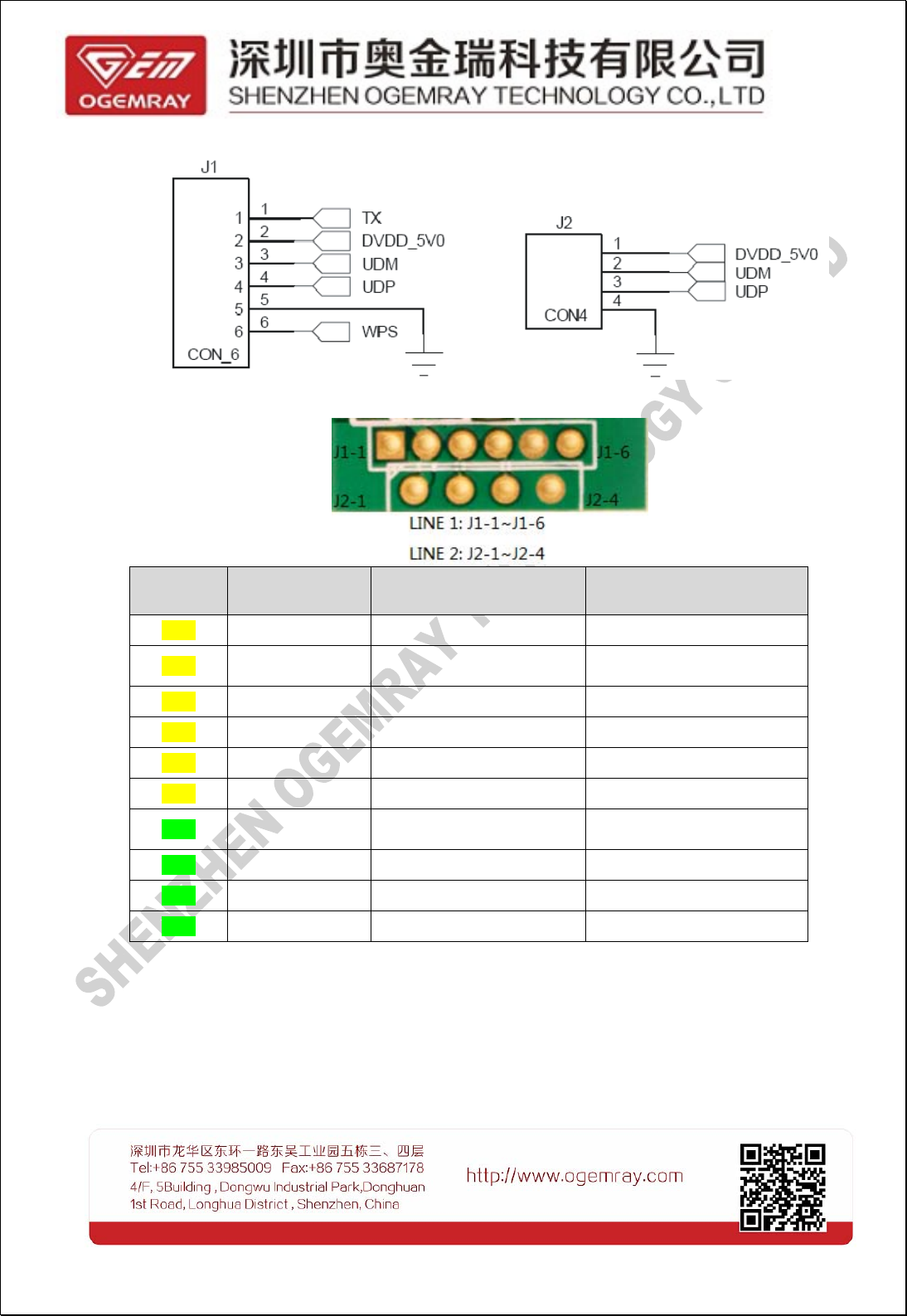
2. Pin diagram of 4/6-pin connector:
3. Pin definition and related function description:
Pin No. Definition Description Remark
J1-1 TX RF Transmitter Enable 3.3V, high level
J1-2 DVDD-5V0 USB Power Supply USB Power supply, DC 5V
+/-0.5V
J1-3 UDM Data-
J1-4 UDP Data+
J1-5 GND GND
J1-6 WPS WPS Buttoninput port 3.3V, low level
J2-1 DVDD-5V0 USB Power Supply USB Power supply, DC 5V
+/-0.5V
J2-2 UDM Data -
J2-3 UDP Data +
J2-4 GND GND
Careful consideration must be paid when selecting pull -up ( or down ) resistors.
J1-1(TX) has a embedded pull-up resistor, and it can be connected directly, 3.3V high level.
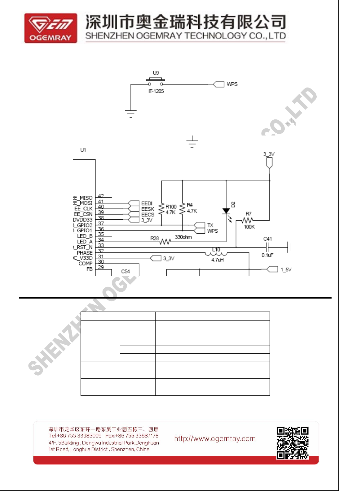
8 / 14
J1-6(WPS) can be grounded by pressing down WPS(U9) button, it is 3.3V low level as the picture
below referred:
The following diagram is our recommended circuit connection:
2
2.
.3
3
S
So
of
ft
tw
wa
ar
re
e
I
In
nf
fo
or
rm
ma
at
ti
io
on
n
The table below is for users to check the available Operation System and its version:
OS Available OS Version
Windows
YES XP
YES Win7
YES Win8
YES Win2000
YES Vista
Linux YES 2.6 or above, only support STA mode
Android YES 2.6 or above, only support STA mode
Mac YES 10.3-10.10
WinCE NO Invalid
2
2.
.4
4
M
Me
e
c
c
2
2.
.4
4.
.1
1
P
Pr
r
o
The vi
e
2
2.
.4
4.
.2
2
P
Pr
r
o
The di
m
c
c
h
ha
an
ni
ic
ca
a
l
l
o
o
d
du
uc
ct
tA
A
p
p
e
w of top a
n
o
o
d
du
uc
ct
t
D
D
i
i
mension of
l
l
I
In
nf
fo
or
rm
m
a
a
p
p
p
pe
ea
ar
ra
an
n
c
c
n
d bottom l
a
i
i
m
me
en
ns
si
io
o
n
n
GWF-5M01
a
a
t
ti
io
on
n
c
c
e
e
yer of GWF
n
n
can be ref
e
9 / 14
F
-5M01 can
e
rred by the
b
e displaye
d
following pi
d
in the foll
o
c
ture:
o
wing pictur
e
e
s:
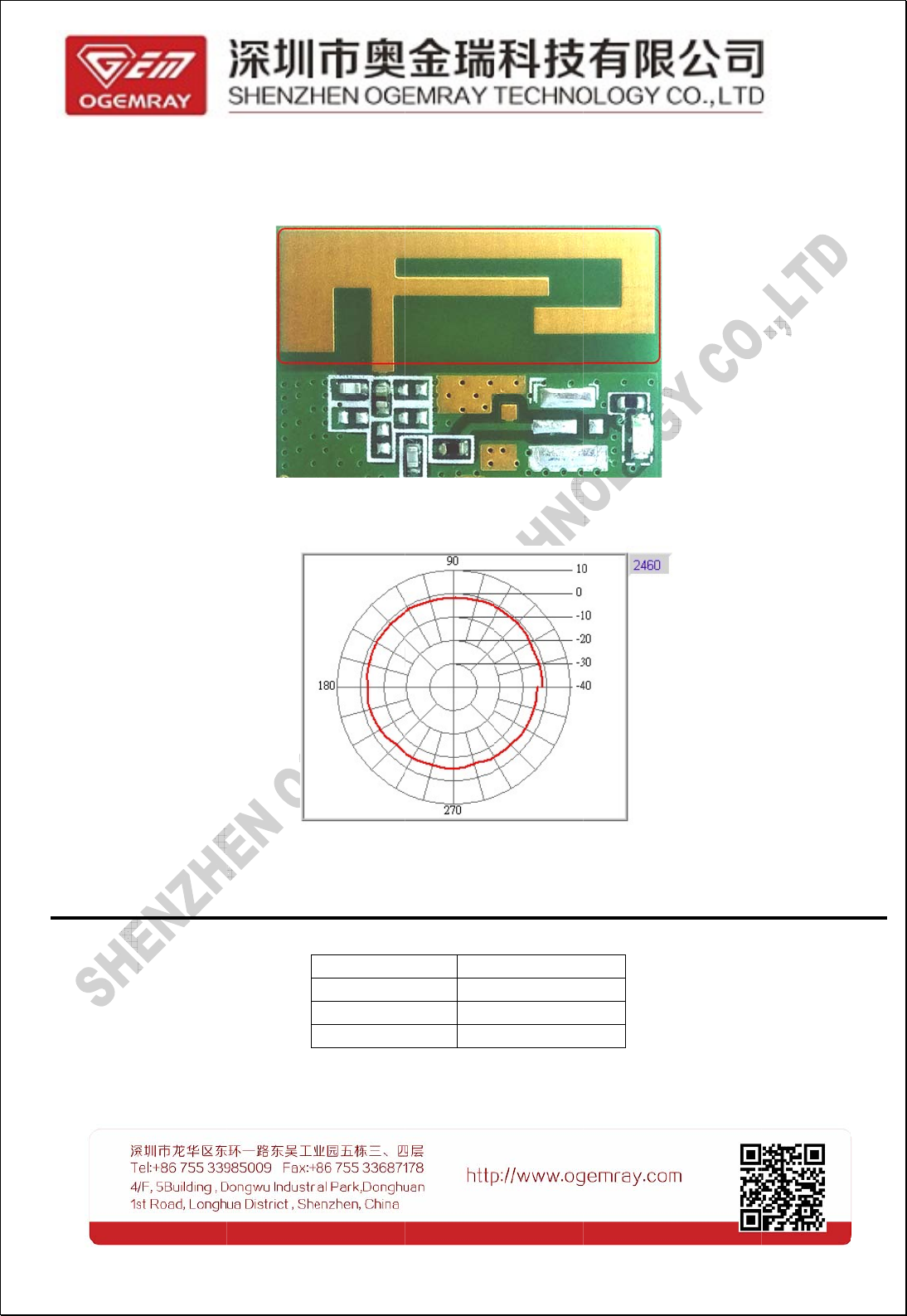
B. On
b
The o
n
antenna d
o
Peak
g
3
3.
.A
Ag
ge
e
n
Our pr
b
oard PCB
n
board ante
o
es not sati
s
g
ain value i
s
n
n
c
cy
y
A
A
p
p
r
oducts are
s
antenna
nna is desi
g
s
fy user's a
p
s
: -1dBi, an
d
p
p
p
pr
ro
ov
va
a
s
trictly confi
r
g
ned with ti
n
p
plication, pl
e
d
the averag
l
l
r
med to the
s
Agen
c
FCC
CE
RoH
S
11 / 1
4
n
y space wh
ease use o
t
e gain valu
e
s
e certificat
e
c
y
S
4
ich affects t
h
t
her externa
e
is: -3dBi.
e
s:
Approval
Undergoin
g
Undergoin
g
Undergoin
g
h
e signal p
e
l
antenna.
g
g
g
e
rformance.
If the onbo
a
a
rd
4
4.
.E
En
nv
v
i
i
4
4.
.1
1
S
Su
ui
i
t
t
Worki
Stora
g
4
4.
.2
2
S
Su
ui
i
t
t
Worki
Stora
g
Notic
e
device, pl
e
i
i
r
ro
on
nm
m
e
e
t
t
a
ab
bl
le
e
T
Te
e
ng Temper
a
g
e Tempera
t
t
t
a
ab
bl
le
e
H
H
u
u
ng Humidit
y
g
e Humidity
e
: To keep
e
ase use it
e
e
n
nt
t
R
Re
e
q
q
m
mp
pe
er
ra
at
t
u
u
a
ture: -5℃~
+
t
ure: -20℃
~
u
u
m
mi
id
di
it
ty
y
y
: 20%~85
%
: 20%~90
%
the norm
a
and store i
t
q
q
u
ui
ir
re
e
m
m
u
u
r
re
e
+
50℃
~
+85℃
%
%
l service li
t
abide by
e
12 / 1
4
m
m
e
en
nt
ts
s
fe and en
s
e
nvironme
n
4
s
ure the e
x
n
t require
m
cellent wo
r
ents strictl
y
r
king perf
o
y.
o
rmance of
our

14 / 14
6
6.
.
D
Di
is
sc
cl
la
ai
im
me
er
r
This DATA SHEET document is the guidance of the installation and tentativeusage of our products.
Before operating the product, please read this data sheet carefully.
All rights reserved. Any reproduction, translation or simplification of this data sheet inwhole or in part is
strictly prohibited without written permission from our company.
We do not provide any guarantee about this data sheet, software or other relevantinformation. We
solemnly state that there is no implied business warranty or commercialcontract assurance in the sheet,
software or other related information. The data sheet is onlyfor operation guidance and reference; it cannot
be used as basis or supplement of anyother contract or duty.

Ver1.0 June 7, 2016
Regulatory information for the OEMs and Integrators
The guidelines described within this document are provided to OEM integrators installing
5G module in notebook and tablet PC host platforms. Adherence to these requirements is
necessary to meet the conditions of compliance with FCC rules, including RF exposure.
When all antenna type and placement guidelines described herein are fulfilled the 5G
Module may be incorporated into notebook and tablet PC host platforms with no further
restrictions. If any of the guidelines described herein are not satisfied it may be necessary
for the OEM or integrator to perform additional testing and/or obtain additional approval.
The OEM or integrator is responsible to determine the required host regulatory testing
and/or obtaining the required host approvals for compliance
. 5G module are intended for OEMs and host integrators only.
. The 5G Module must be operated with an access point that has been approved for the
country of operation.
. Changes or modification to 5G Module by OEMs, integrators or other third parties is not
permitted. Any changes or modification to 5G Module by OEMs, integrators or other third
parties will void authorization to operate This module is not masked, and the end user
needs to increase the mask.
Information to Be Supplied to the End User by the OEM or Integrator
The following regulatory and safety notices must be published in documentation supplied
to the end user of the product or system incorporating the Amplified 5G Module, in
compliance with local regulations.
Host system must be labeled with "Contains FCC ID: YWTGWF-5M01 ", FCC ID displayed
on label.
The 5G Module must be installed and used in strict accordance with the manufacturer's
instructions as described in the user documentation that comes with the product. Intel
Corporation is not responsible for any radio or television interference caused by
unauthorized modification of the devices included with the wireless adapter kit or the
substitution or attachment of connecting cables and equipment other than that specified
by Intel Corporation. The correction of interference caused by such unauthorized
modification, substitution or attachment is the responsibility of the user. Intel Corporation
and authorized resellers or distributors are not liable for any damage or violation of
government regulations that may arise from the user failing to comply with these
guidelines.
This device has been evaluated and shown compliant with the FCC RF Exposure limits
under fixed exposure conditions (antennas are greater than 20cm from a person’s
body)when installed in certain specific configurations.
The host system shall have a label showing: Contains FCC ID: YWTGWF-5M01
This product only used external antenna, The gain of antenna : -1.0dBi
FCC Caution: Any changes or modifications not expressly approved by the party responsible for
compliance could void the user's authority to operate this equipment.
This device complies with Part 15 of the FCC Rules. Operation is subject to the following two conditions:
(1) This device may not cause harmful interference, and (2) this device must accept any interference
received, including interference that may cause undesired operation.
This device and its antenna(s) must not be co-located or operating in conjunction with any other antenna

Ver1.0 June 7, 2016
or transmitter.
15.105 Information to the user.
(b) For a Class B digital device or peripheral, the instructions furnished the user shall include the
following or similar statement, placed in a prominent location in the text of the manual:
Note: This equipment has been tested and found to comply
with the limits for a Class B digital device, pursuant to part 15 of the FCC Rules.
These limits are designed to provide reasonable protection against harmful interference in a residential
installation. This equipment generates, uses and can radiate radio frequency energy and, if not installed
and used in accordance with the instructions, may cause harmful interference to radio communications.
However, there is no guarantee that interference will not occur in a particular installation. If this
equipment does cause harmful
interference to radio or television reception, which can be determined by turning the equipment off and on,
the user is encouraged to try to correct the interference by one or more of the following measures:
—Reorient or relocate the receiving antenna.
—Increase the separation between the equipment and receiver.
—Connect the equipment into an outlet on a circuit different from that to which
the receiver is connected.
—Consult the dealer or an experienced radio/TV technician for help.
This equipment complies with FCC radiation exposure limits set forth for an uncontrolled environment.
This equipment should be installed and operated with minimum distance 20cm between the radiator
and your body.
Radiation Exposure Statement:
This equipment complies with FCC radiation exposure limits set forth for an uncontrolled environment.
This transmitter must not be co-located or operating in conjunction with any other antenna or transmitter.
The availability of some specific channels and/or operational frequency bands are country dependent
and are
firmware programmed at the factory to match the intended destination.
The firmware setting is not accessible by the end user.
For 5180~5240MHz, this device is only used for indoor.