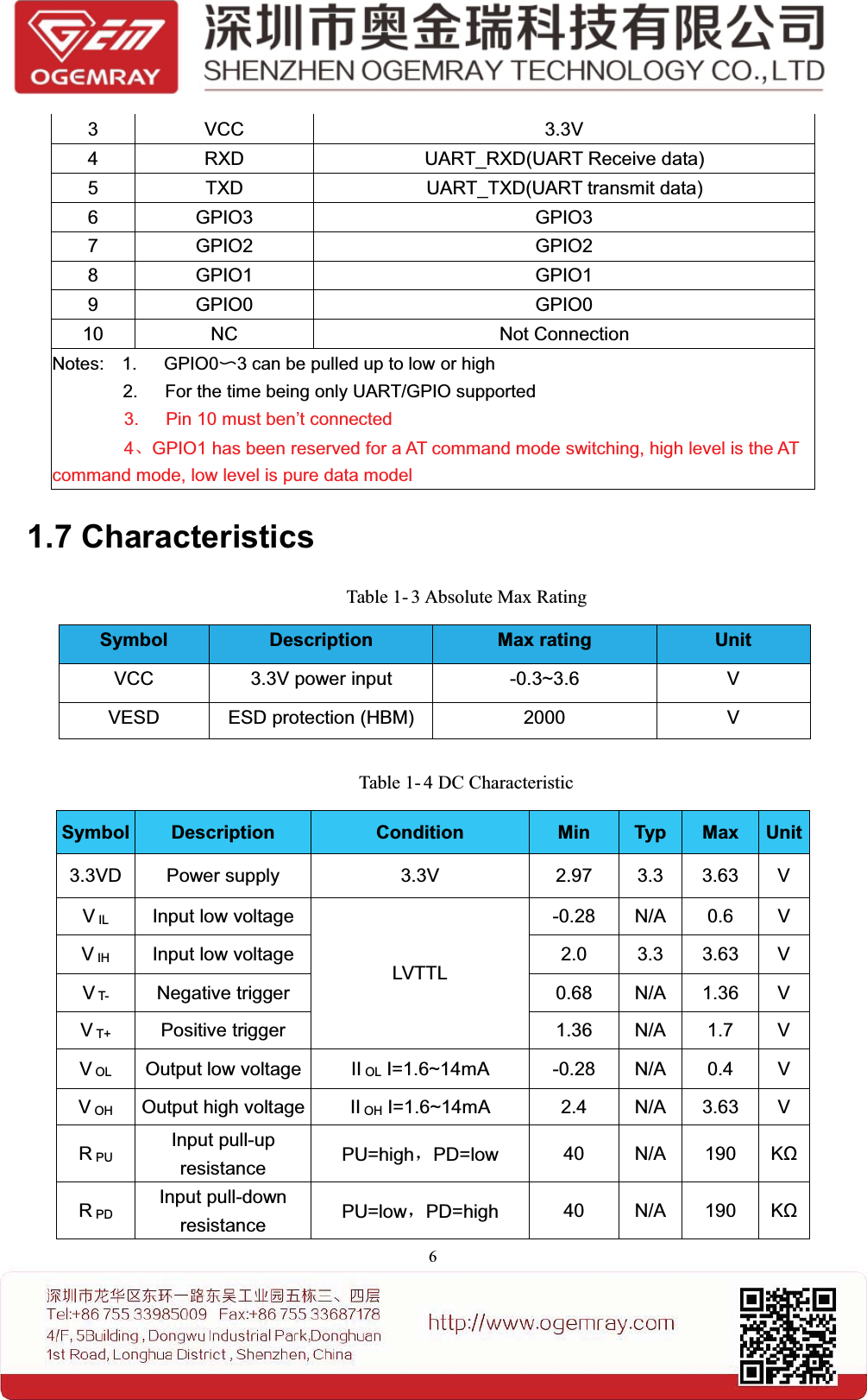
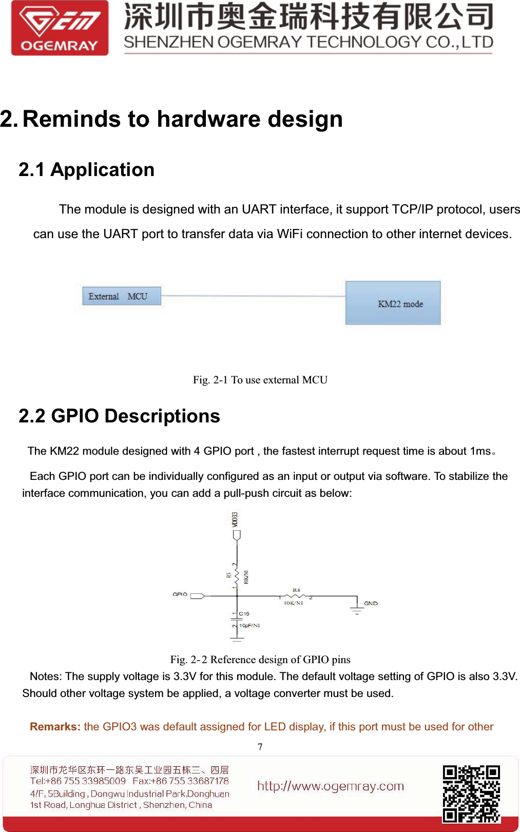
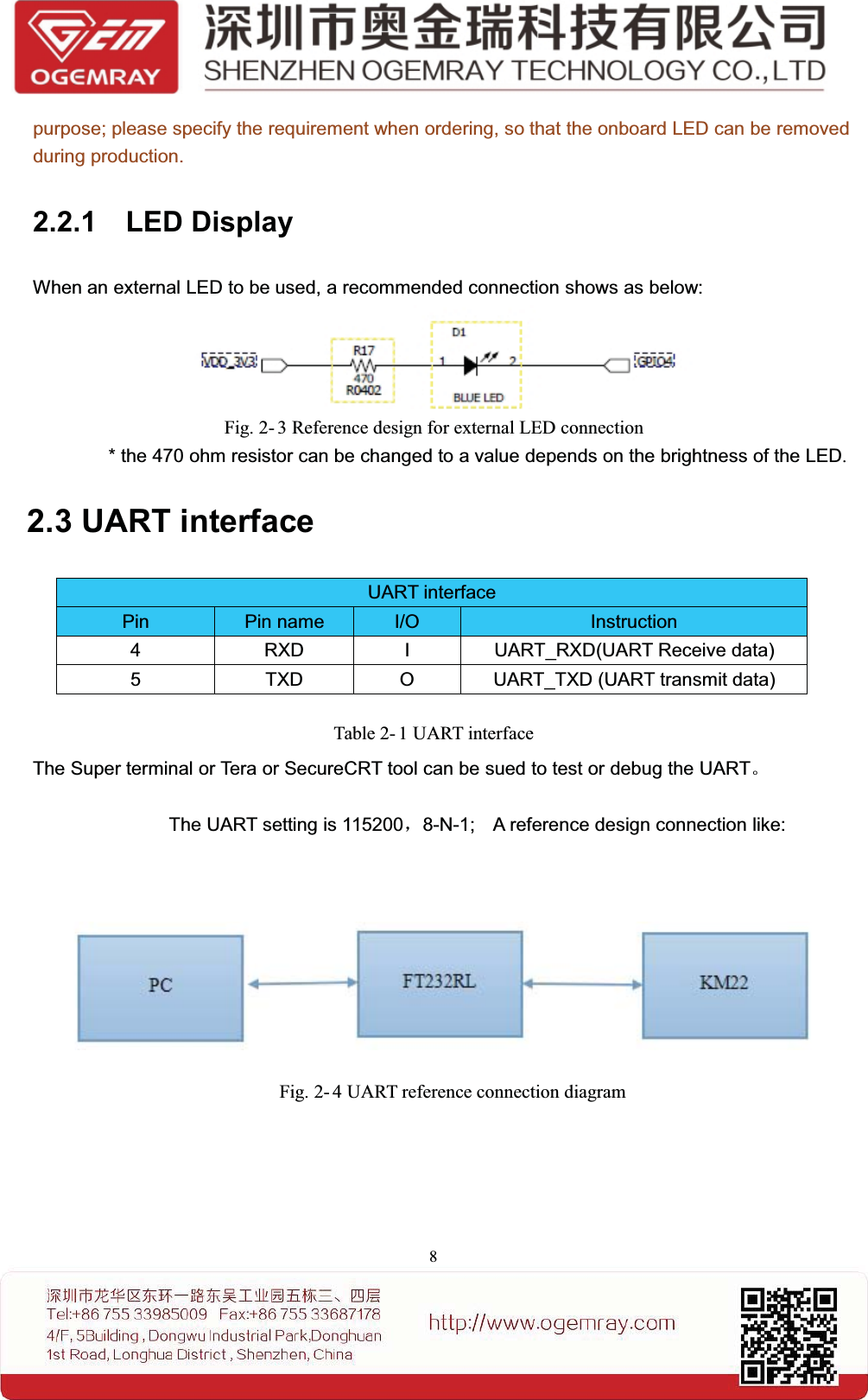
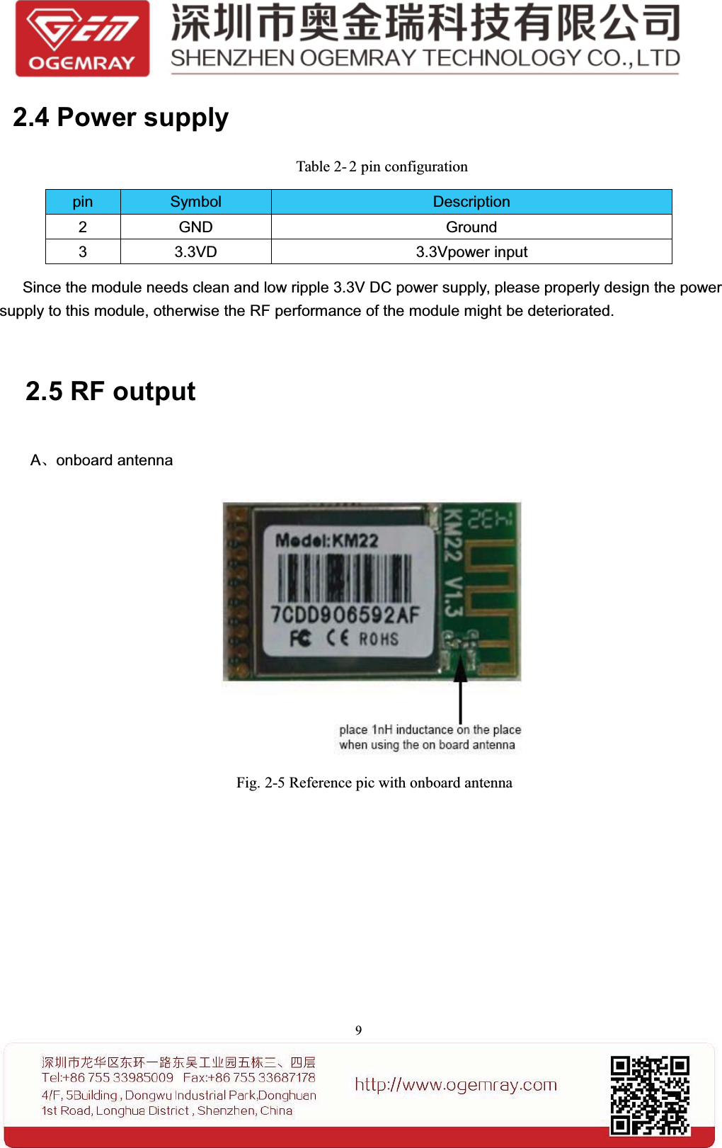
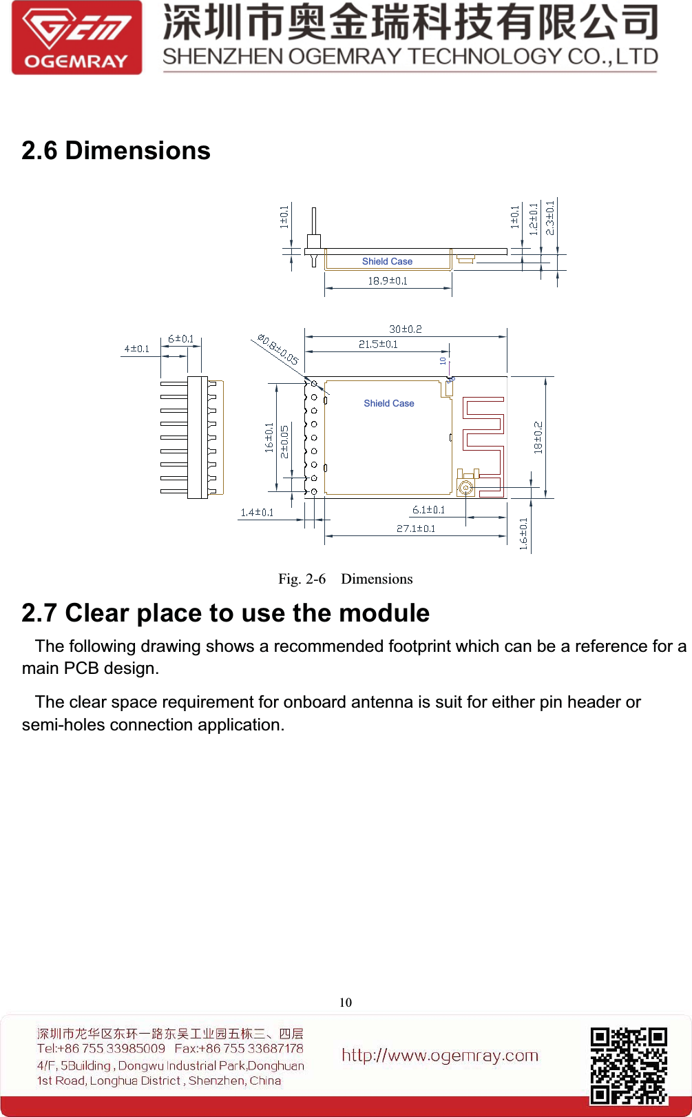
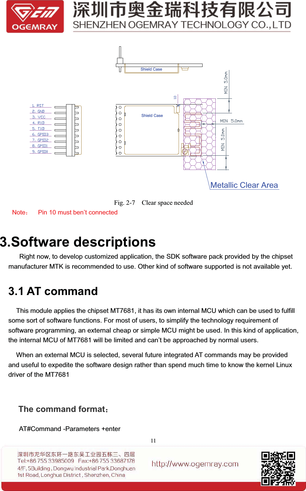
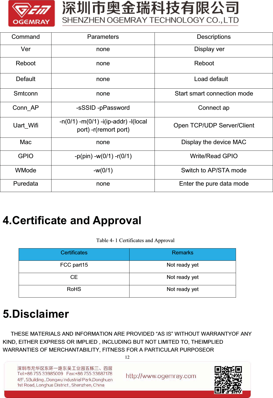
Ogemray Technology WF7681KMX UART WiFi Module User Manual x005f x0001

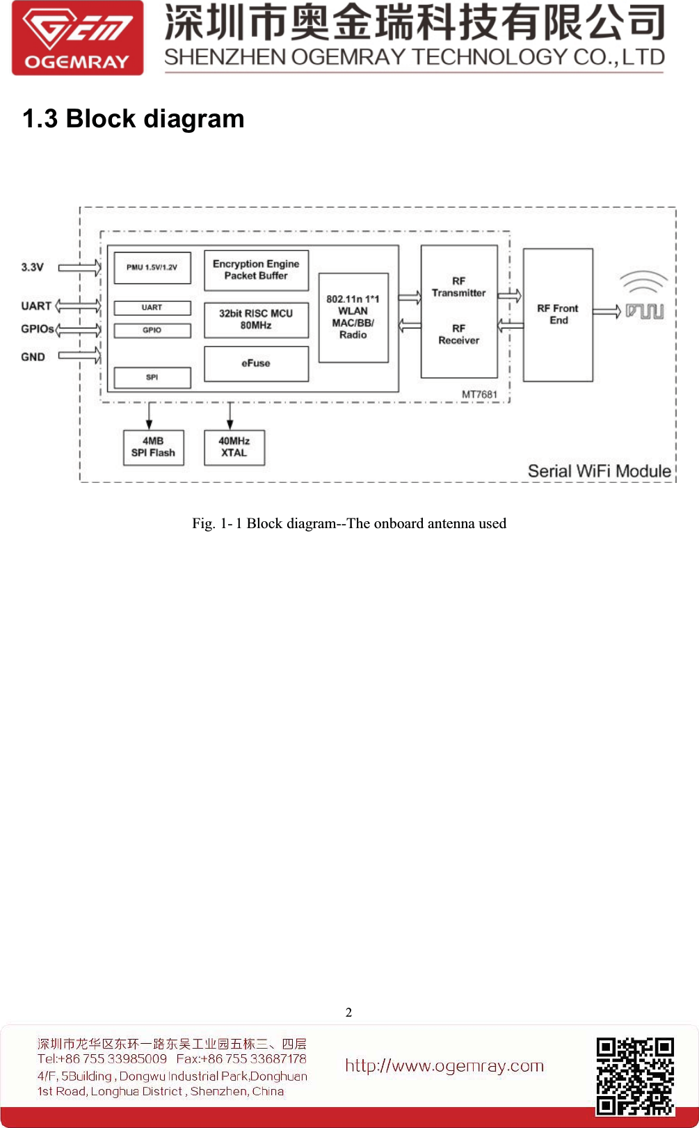
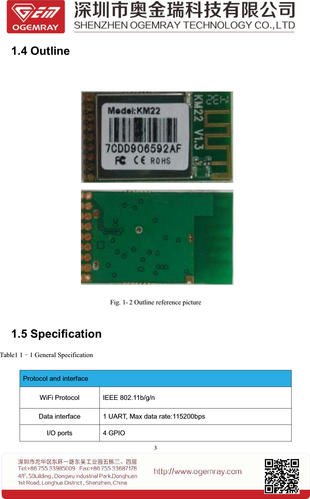
Shenzhen Ogemray Technology Co.,Ltd UART WiFi Module x005f x0001

User manual

SSpecificationUART WiFi ModuleGWF-KM22(2.4GHz 802.11 b/g/n)Ver: 1.22014-10-17
Contents1. Introduction............................................................................................................................................................... 11.1 Profile................................................................................................................................................................11.2 Features............................................................................................................................................................. 11.3 Block diagram...................................................................................................................................................21.4 Outline...............................................................................................................................................................31.5 Specification..................................................................................................................................................... 41.6 Pinout configuration......................................................................................................................................... 61.7 Characteristics...................................................................................................................................................72. Reminds to hardware design................................................................................................................................. 82.1 Application........................................................................................................................................................ 82.2 GPIO Descriptions............................................................................................................................................82.2.1 LED Display......................................................................................................................................92.3 UART interface................................................................................................................................................. 92.4 Power supply.....................................................................................................................................................92.6 Dimensions................................................................................................................................................... 132.7 Clear place to use the module.................................................................................................................. 133.Software descriptions.............................................................................................................................................143.1 AT command.................................................................................................................................................144.Certificate and Approval.........................................................................................................................................155.Disclaimer.................................................................................................................................................................15
Figures and tablesTable 1-1 General Specification.................................................................................................................................. 3Table 1-2 Pin configuration......................................................................................................................................... 5Table 1-3 Absolute Max Rating................................................................................................................................... 6Table 1-4 DC Characteristics....................................................................................................................................... 6Table 2-1 UART interface............................................................................................................................................7Table 2-2 Power input..................................................................................................................................................8Table 5-1 Certificates and Approval.......................................................................................................................... 15Fig. 1-1 Block diagram-An onboard antenna used......................................................................................................2Fig. 1-2 Outline reference picture................................................................................................................................3Fig. 1-3 Pin definition overview..................................................................................................................................5Fig. 2-1 To use external MCU ................................................................................................................................... 6Fig. 2-2 Reference design of GPIO pins......................................................................................................................7Fig. 2-3 Reference design for external LED connection.............................................................................................7Fig. 2-4 UART reference connection diagram............................................................................................................ 9Fig. 2-5 Ref pic with onboard antenna........................................................................................................................ 9Fig. 2-6 Dimensions...................................................................................................................................................10Fig. 2-7 Clear space needed..................................................................................................................................... 11
11. Introduction1.1 ProfileThe GWF-KM22 module operates in 2.4GHz ISM frequency band with low power consumption; itapplies a highly integrated MAC/BBP in the MT7681 chipset, support IEEE的802.11b/g/n standards with1T1R technology.This module supports TCP/IP,UDP protocol ,its low cost and low power consumption, easy usingcharacteristics make the wireless connection become easy and reliable.The single side components mounted module provide 1 UART interface and 4 GPIO ports. The optionalon-board or external antenna easy the downstream RF hardware technology requirement. A set of futureprovided serial AT commands can simplify software design, thus a normal, simple, cheap MCU can beused to control the WiFi module easily.The module includes a number of TCP/IP-based connectivity protocols enabling a low-cost,low-complexity system to contain full-featured internet connectivity and reliable information exchange.This module is mainly used in a multitude of smart home appliances and consumer electronics such asremote control, thermostats, power socket, WIFI audio transmission, LED control, wireless sensor, etcand other applications.1.2 FeaturesSupports 2.4GHz, 802.11b/g/n Client and AP modeInternal MCU development SDK supported.Smart WiFi configuration supported.Provide 1 UART and 4 GPIO ports.Support WEP,WPA2 encryption modeSelection Client and AP modeRF ON/OFF control, Sleep mode power management.Optional onboard antenna .
21.3 Block diagramFig. 1- 1 Block diagram--The onboard antenna used
31.4 OutlineFig. 1- 2 Outline reference picture1.5 SpecificationTable1 1–1 General SpecificationProtocol and interfaceWiFi Protocol IEEE 802.11b/g/nData interface 1 UART, Max data rate:115200bpsI/O ports 4 GPIO
4LED display Link/Activity displayMemory sizeExternal SPI Flash 4MbitWiFi FeaturesWiFi mode Client / Soft AP modeEncryption WPA2-PSK,WEP ( more will be available later)WiFi RF CharacteristicsFrequency ISM band, 2412~2462MHz.Tx power(Peak value)802.11b (CCK) 11Mbps: 19.5+/-1dBm802.11g (OFDM) 54Mbps: 21.5+/-1dBm802.11n(HT20@MCS7),20.5+/-1dBmRx sensitivity802.11b: -86+/-1dBm;802.11g: -72+/-1dBm,802.11n (HT20), -68+/-1dBm;Operation Voltage and Current (Typical)Power supply 3.3+/-0.05 VDCCurrent1.1mA Sleep mode6mA RX listen mode15mA RX power saving, DTIM=170mA RX Active、MCS7220mA 802.11g (OFDM) 54Mbps210mA 802.11n (HT20@MCS7)245mA 802.11b (CCK) 11MbpsOperation ConditionOperating temperature -10ºC to +60ºCStorage temperature -20ºC to +80ºC
5Operating humidity 20% to 80%PhysicalSize 30*18mmWeight 2.4g1.6 Pinout configurationShield CaseShield CaseLEDFig. 1- 3 Pin definition overviewTable1 1–2Pin configurationPin Name Description1 RST External reset active low2GND GND
63VCC 3.3V4 RXD UART_RXD(UART Receive data)5 TXD UART_TXD(UART transmit data)6 GPIO3 GPIO37 GPIO2 GPIO28 GPIO1 GPIO19 GPIO0 GPIO010 NC Not ConnectionNotes: 1. GPIO0〜3 can be pulled up to low or high2. For the time being only UART/GPIO supported3. Pin 10 must ben’t connected4、GPIO1 has been reserved for a AT command mode switching, high level is the ATcommand mode, low level is pure data model1.7 CharacteristicsTable 1- 3 Absolute Max RatingSymbol Description Max rating UnitVCC 3.3V power input -0.3~3.6 VVESD ESD protection (HBM) 2000 VTable 1- 4 DC CharacteristicSymbol Description Condition Min Typ Max Unit3.3VD Power supply 3.3V 2.97 3.3 3.63 VVIL Input low voltageLVTTL-0.28 N/A 0.6 VVIH Input low voltage 2.0 3.3 3.63 VVT- Negative trigger 0.68 N/A 1.36 VVT+ Positive trigger 1.36 N/A 1.7 VVOL Output low voltage II OL I=1.6~14mA -0.28 N/A 0.4 VVOH Output high voltage II OH I=1.6~14mA 2.4 N/A 3.63 VRPUInput pull-upresistance PU=high,PD=low 40 N/A 190 KΩRPDInput pull-downresistance PU=low,PD=high 40 N/A 190 KΩ
72. Reminds to hardware design2.1 ApplicationThe module is designed with an UART interface, it support TCP/IP protocol, userscan use the UART port to transfer data via WiFi connection to other internet devices.Fig. 2-1 To use external MCU2.2 GPIO DescriptionsThe KM22 module designed with 4 GPIO port , the fastest interrupt request time is about 1ms。Each GPIO port can be individually configured as an input or output via software. To stabilize theinterface communication, you can add a pull-push circuit as below:Fig. 2- 2 Reference design of GPIO pinsNotes: The supply voltage is 3.3V for this module. The default voltage setting of GPIO is also 3.3V.Should other voltage system be applied, a voltage converter must be used.Remarks: the GPIO3 was default assigned for LED display, if this port must be used for other
8purpose; please specify the requirement when ordering, so that the onboard LED can be removedduring production.2.2.1 LED DisplayWhen an external LED to be used, a recommended connection shows as below:Fig. 2- 3 Reference design for external LED connection* the 470 ohm resistor can be changed to a value depends on the brightness of the LED.2.3 UART interfaceTable 2- 1 UART interfaceThe Super terminal or Tera or SecureCRT tool can be sued to test or debug the UART。The UART setting is 115200,8-N-1; A reference design connection like:Fig. 2- 4 UART reference connection diagramUART interfacePin Pin name I/O Instruction4 RXD I UART_RXD(UART Receive data)5 TXD O UART_TXD (UART transmit data)
92.4 Power supplyTable 2- 2 pin configurationpin Symbol Description2 GND Ground3 3.3VD 3.3Vpower inputSince the module needs clean and low ripple 3.3V DC power supply, please properly design the powersupply to this module, otherwise the RF performance of the module might be deteriorated.2.5 RF outputA、onboard antennaFig. 2-5 Reference pic with onboard antenna
102.6 DimensionsShield CaseShield CaseLEDFig. 2-6 Dimensions2.7 Clear place to use the moduleThe following drawing shows a recommended footprint which can be a reference for amain PCB design.The clear space requirement for onboard antenna is suit for either pin header orsemi-holes connection application.
11Shield CaseShield CaseLEDMetallic Clear AreaFig. 2-7 Clear space neededNote:Pin 10 must ben’t connected3.Software descriptionsRight now, to develop customized application, the SDK software pack provided by the chipsetmanufacturer MTK is recommended to use. Other kind of software supported is not available yet.3.1 AT commandThis module applies the chipset MT7681, it has its own internal MCU which can be used to fulfillsome sort of software functions. For most of users, to simplify the technology requirement ofsoftware programming, an external cheap or simple MCU might be used. In this kind of application,the internal MCU of MT7681 will be limited and can’t be approached by normal users.When an external MCU is selected, several future integrated AT commands may be providedand useful to expedite the software design rather than spend much time to know the kernel Linuxdriver of the MT7681The command format:AT#Command -Parameters +enter
12Command Parameters DescriptionsVer none Display verReboot none RebootDefault none Load defaultSmtconn none Start smart connection modeConn_AP -sSSID -pPassword Connect apUart_Wifi -n(0/1) -m(0/1) -i(ip-addr) -l(localport) -r(remort port) Open TCP/UDP Server/ClientMac none Display the device MACGPIO -p(pin) -w(0/1) -r(0/1) Write/Read GPIOWMode -w(0/1) Switch to AP/STA modePuredata none Enter the pure data mode4.Certificate and ApprovalTable 4- 1 Certificates and ApprovalCertificates RemarksFCC part15 Not ready yetCE Not ready yetRoHS Not ready yet5.DisclaimerTHESE MATERIALS AND INFORMATION ARE PROVIDED “AS IS” WITHOUT WARRANTYOF ANYKIND, EITHER EXPRESS OR IMPLIED , INCLUDING BUT NOT LIMITED TO, THEIMPLIEDWARRANTIES OF MERCHANTABILITY, FITNESS FOR A PARTICULAR PURPOSEOR
13NON-INFRINGEMENT.We use reasonable efforts to include accurate and up-to-date information on this document; it does not,however, make any representations as to its accuracy or completeness of the information, text, graphics,links or other items contained within these materials. Your use of this Document is at your own risk.Ogemray, its suppliers, and other parties involved in creating and delivering this Document’s contentsshall not be liable for any special, indirect, incidental, or consequential damages, including withoutlimitation, lost revenues or lost profits.FCC StatementThis device complies with Part 15 of the FCC Rules. Operation is subject to the following two conditions:(1) this device may not cause harmful interference, and (2) this device must accept any interferencereceived, including interference that may cause undesired operation.Caution!Any changes or modifications not expressly approved by the party responsible for compliance couldvoid the user's authority to operate the equipment.FCC Radiation Exposure StatementThe modular can be installed or integrated in mobile or fix devices only. This modular cannot be installedin any portable device, for example, USB dongle like transmitters is forbidden.This modular complies with FCC RF radiation exposure limits set forth for an uncontrolled environment.This transmitter must not be co-located or operating in conjunction with any other antenna or transmitter.This modular must be installed and operated with a minimum distance of 20 cm between the radiator anduserbody.If the FCC identification number is not visible when the module is installed inside another device, then the outside of the device into which the module is installed must also display a label referring to the enclosed module. This exterior label can use wording such as the following: Contains Transmitter Module FCCID: YWTWF7681KMX or Contains FCC ID: YWTWF7681KMXwhen the module is installed inside another device, the user manual of this device must contain below warning statements;1. This device complies with Part 15 of the FCC Rules. Operation is subject to the following two conditions:(1) This device may not cause harmful interference.(2) This device must accept any interference received, including interference that may cause undesired operation.
142. Changes or modifications not expressly approved by the party responsible for compliance could void the user's authority to operate the equipment.The devices must be installed and used in strict accordance with the manufacturer's instructions as described in the user documentation that comes with the product.

Navigation menu