Ohsung Electronics URCMRF260 RF RECEIVER User Manual I
Ohsung Electronics Co., Ltd. RF RECEIVER I
UserManual.wiki
>
Ohsung Electronics
>
URCMRF260 User Manual
>
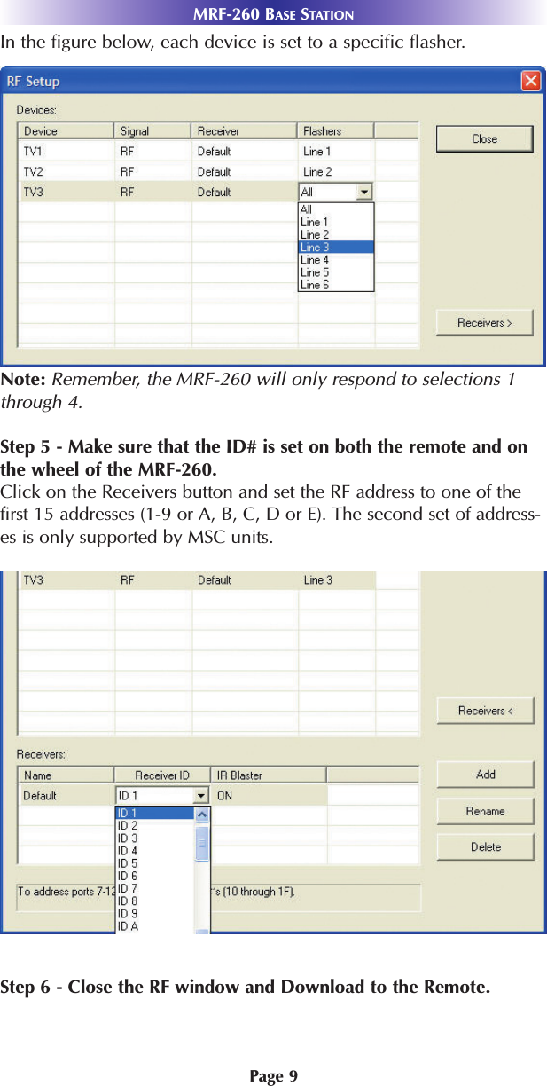
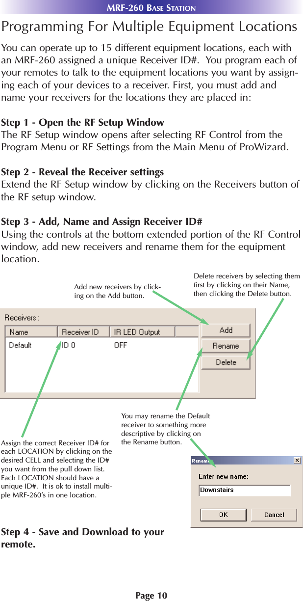
USERS MANUAL
Contents
1.
USERS MANUAL
2.
Users Manual
USERS MANUAL
Navigation menu
Upload a User Manual
Namespaces
Wiki Guide
HTML
PDF
Info
Views
User Manual
Discussion / Help
Navigation