Ohsung Electronics URCMRZ260 RF BASE STATION User Manual User s Manual H
Ohsung Electronics Co., Ltd. RF BASE STATION User s Manual H
Users Manual

Order Number : GETEC-C1-09-088 FCC Part 15 subpart C
Test Report Number : GETEC-E3-09-039 Page 1 / 1
EUT Type: RF Base Station
FCC ID.: OZ5URCMRZ260
APPENDIX H
: USER’S MANUAL
MRZ-260 Installation Manual

MRZ-260 Installation Manual ©2009 Universal Remote Control, Inc.
The information in this manual is copyright protected. No part of this manual may be
copied or reproduced in any form without prior written consent from Universal Remote
Control, Inc.
UNIVERSAL REMOTE CONTROL, INC. SHALL NOT BE LIABLE FOR OPERATIONAL,
TECHNICAL OR EDITORIAL ERRORS/OMISSIONS MADE IN THIS MANUAL.
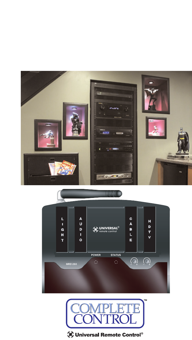
The Home Theater installation on the cover was designed and installed by Stone-
Glidden of King of Prussia and Doylestown, PA.
The information in this manual may be subject to change without prior notice.
Complete Control is a registered trademark of Universal Remote Control, Inc.
All other brand or product names are trademarks or registered trademarks of their respec-
tive companies or organizations.
500 Mamaroneck Avenue, Harrison, NY 10528
Phone: (914) 835-4484 Fax: (914) 835-4532

TABLE OFCONTENTS
Introduction 1
Features and Benefits 2
Parts Guide 2
Installation 3
Testing 5
Front Blaster Overload 7
Disabling the Front Blaster - Step by Step via PC 7
Controlling Four Identical Components/Zones 8
Identical Components/Zones - Step by Step via PC 8
Programming For Multiple Equipment Locations 10
USA Limited Warranty Statement 11
Frequently Asked Questions 12
Specifications 12
Federal Communication Commission Interference Statement
13
Page 1
MRZ-260 BASE STATION
Introduction
The MRZ-260 base station has incorporated a new wireless technolo-
gy referred to as Zigbee. This technology improves the range and reli-
ability throughout a house and gives you the ability to control as
many identical components as needed. In order to control a Zigbee
base station an Zigbee remote is needed such as the MX-880Z.
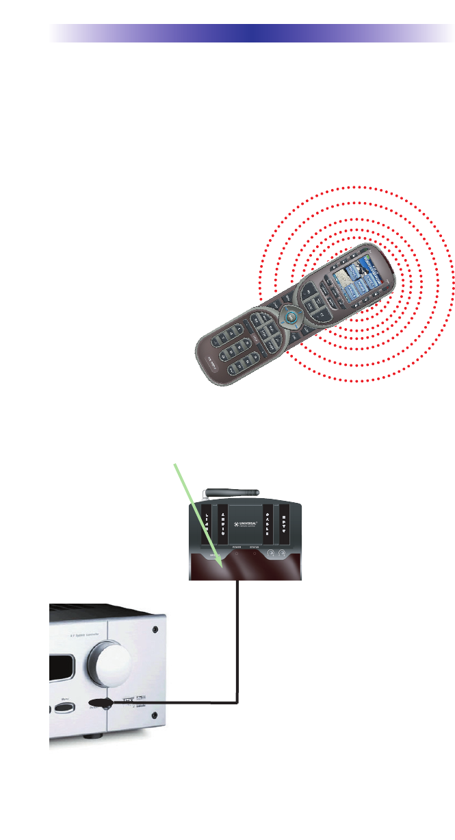
3. Self-adhesive “Flashers” affix to
the Infrared sensors on the front pan-
els of your components. The
Flashers relay commands to compo-
nents out of sight of the MRZ-260
Front Blaster. The flashers plug in to
the MRZ-260 rear flasher line out-
puts via their 10 foot cables.
Uniquely, the MRZ-260 can also
connect to components with rear
panel IR Inputs via its adjustable IR
Line Outputs.
2. The MRZ-260 built-in Front Blaster sends commands to com-
ponents in the same cabinet space or you can use flashers.
1. The MX-880Z sends radio
waves in every direction, so you
don’t have to point the remote
anymore!

Page 2
MRZ-260 BASE STATION
Features and Benefits
Interference Rejection and Extended Range via Zigbee
The MRZ-260 receives Zigbee signals via its integrated receiver and anten-
na and is the only wireless standards-based technology:
* allows omni-directional control
* enables broad-based deployment of wireless networks with low cost,
low power solutions.
* provides the ability to run for years on inexpensive primary batteries for
a typical home theatre application.
Two Fixed IR Outputs with RFTX URC Lighting Control
The MRZ-260 is equipped with two fixed IR line outputs with standard 3.5
mm jacks for standard and sleeved IR emitter/flashers. One Fixed IR Output
has a dual role for URC Ligting Control via the RFTX transmitter
Two Variable IR Outputs Match Rear Panel IR Inputs
The MRZ-260 is equipped with two adjustable IR line outputs. Each output
can be individually matched to rear panel IR inputs on any component that
is designed to be operated by a standard IR repeater. The outputs utilize a
3.5mm jack and are compatible with standard IR emitter/flashers as well.
No Limit Equipment Locations With Identical Components
Each MX remote is “addressable.” They can be programmed to specifically
control components in a particular room by installing an MRZ-260 base sta-
tion at each location. In operation it’s simple: when you select a device
located in the Den, the MX remote only sends commands to the Den.
When you select a device located in the Family Room, the MX remote only
sends commands to it.
A Single MRZ-260 Can Control an Array of Identical Components or
Identical Zones of a Multi Zone Preamp/Matrix Switcher
Each MRZ-260 has four “addressable” IR Line Outputs. For example, you
can control up to four identical TV’s with one MRZ-260 or route volume
commands for a specific zone to a particular zone IR input on a multi-zone
preamp. If you have more than four identical components or zones, there
is no limit on how many MRZ-260s can be installed to control them (thus
allowing an unlimited amount of identical components or zones in one
house).
Parts Guide
The MRZ-260 RF Base Station includes:
1 - MRZ-260 Base Station
1 - Mounting Plate for wall mounting
the MRZ-260
4 - Screws for wall mounting
1 - 9V-300mA Power Supply
12 - Labels for IR Line Outputs
4 - Visible Flashers with 10 foot plug in
cables including 1 pink sleeved
emitter for the RFTX-1 port
4 - Extra self adhesive pads for Emitters
1 - Screwdriver for Variable Outputs
Page 3
Installation and MAC Address Discovery
1. Unplug the MRZ-260. Test all IR commands and macros line of sight.
2. Power on all AV components including the TV. Turn on all of the
lights and lower all dimmers to 50%. Power on anything that may cre-
ate Interference (particularly devices with high speed microprocessors
or hard drives).
3. Once all commands and macros work in direct line of sight,
connect the MRZ-260 to its DC wall adapter and plug the wall
adapter into a live AC outlet.
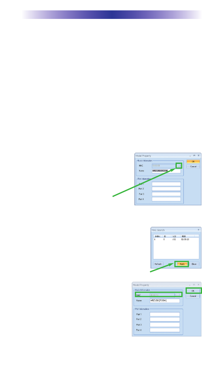
4. The next steps are necessary to “Discover the MRZ-260 base”. Open
CCP editor.
5. Select Program then Configure Home.
6. Add a MRZ-260 base station and the
properties window opens.
7. Plug in a Zigbee remote control such as
the MX-880Z remote via USB to the PC.
8. Click on the Browse button to automati-
cally discover the MAC address of the
MRZ-260 base or type in the 8 characters found on the MAC ID sticker
located in the rear of the base.
Note: If you receive a Not Connected message
simply unplug then replug the USB cable and try
again.
9. Once the MRZ-260 is found, highlight the match-
ing MAC address and select Apply.
10. Now the MAC address will populate the
MAC field.
11. Press OK to close the window and now
the MRZ-260 has been discovered.
12. Place the MRZ-260 in a location at least
3 feet away from satellite receivers,
cable boxes, HDTV tuners, DVRs, PCs or any other device with a
high speed microprocessor (these generate broad band Radio
MRZ-260 BASE STATION
Page 4
Frequency Interference -RFI). Of course, you should keep in mind
that the emitter cables are 10’ long.
13. Observe the Status LED of the MRZ-260.
14. Once you have found a location, test to see if the range is adequate
and that macro reliability is perfect. Start with the antenna angle set to
45 degrees and positioned so that the long side of
the antenna is facing the customer’s favorite seating
position.
15. Now that the location is fixed, connect each of the
emitters to the appropriate IR output and run the cable to the appro-
priate component. Do not attach the emitters to the front panel yet!
Utilize the included preprinted labels to identify which emitter goes
to which component. If you’d like to make your own, the slots for the
labels have been sized at 12mm to enable a Brother P-Touch 12mm
label to fit perfectly.
NOTE: TiVo, Replay TV, other DVRs, Satellite Receivers and Cable Boxes
are all extremely sensitive to IR overload or saturation. For this reason, it
is recommended that you always connect the IR flashers for these types of
component to the Variable IR Outputs of the MRZ-260.
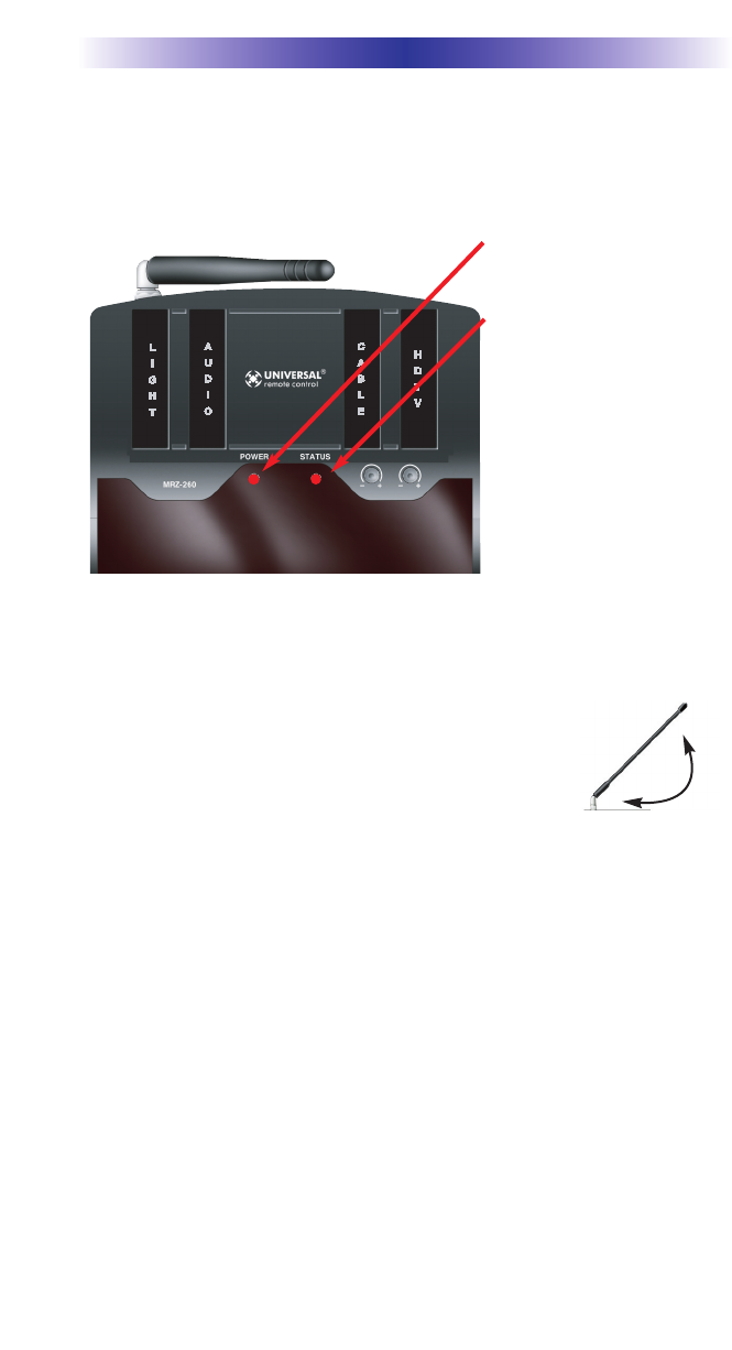
MRZ-260 BASE STATION
The red POWER LED indi-
cates that the MRZ-260 is
powered on.
The red STATUS LED flash-
es when a command is
pressed from the remote.
45°

MRZ-260 BASE STATION
Page 5
Testing
Test a few commands for each device before fixing the flasher in place on
the front panel of a device.
Since TiVo, Replay TV, Satellite Receivers and Cable Boxes are all extremely
sensitive to IR overload or saturation, you should test them thoroughly. Put
up the on screen guide and test the navigation arrows. Compare operation
via RF to the original remote control. Operation should be identical. Zigbee
is not slower.If operation is inconsistent or sluggish, lower the IR line output
and/or reposition the flasher.
If you still have sluggish operation, check that the remote control is set to a
particular LINE OUT, rather than ALL. When IR commands are sent to all
the flashers in a cabinet, you can have difficulty adjusting the IR Output.
Reprogram the remote control to send IR commands only via a specific (1-
4) Line Output, then readjust the IR Line Output level.
Note: Remember, the MRZ-260 will NOT respond if you select IR line out-
puts 5 or 6. The MRZ-260 has only four IR Line Outputs.
1. Connect an IR emitter to each IR output and run the emitter wire to the
front panel of each component. DO NOT STICK the emitter in place.
ADJUST the level first.
2. Adjust each of the IR Output levels for best operation. If the component
operates best at minimum level, but is still operating sluggishly or inter-
mittently, move the emitter farther away from the components IR sensor.
MRZ-260 BASE STATION
Page 6
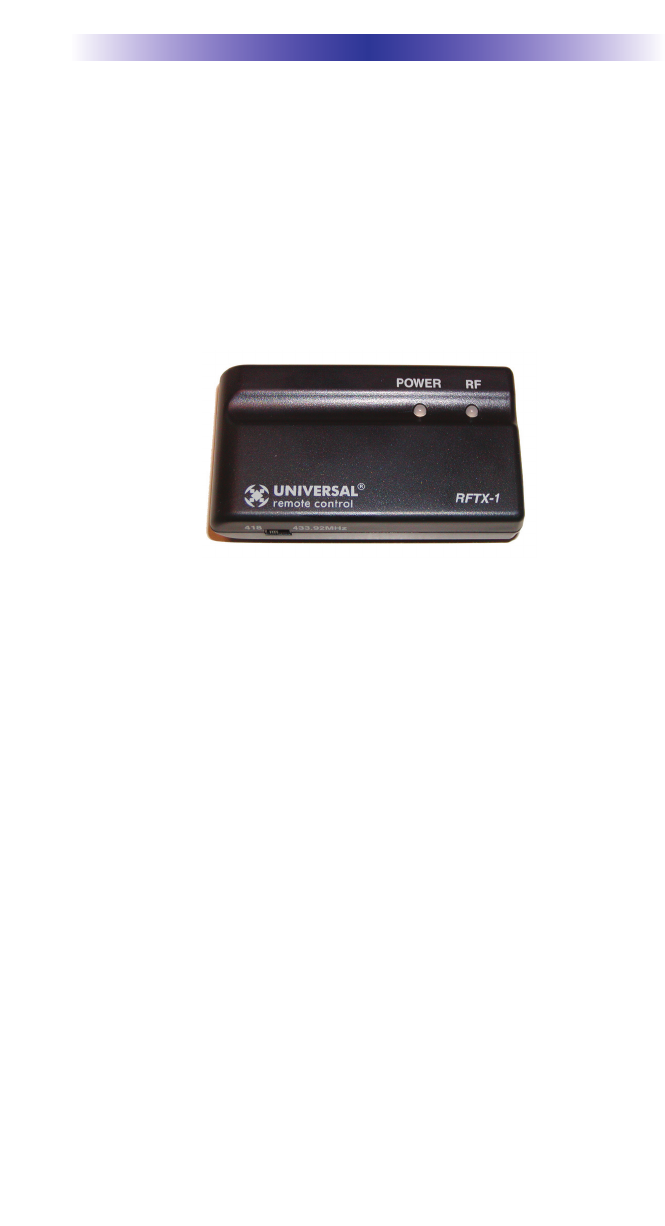
Integrating RFTX-1 to control URC Lighting
Not only will you have greater control of your home theatre equipment with
Zigbee, now you also have control of your URC Lighting. What better way
to watch a movie and control your universe!
Step 1: Simply use a sleeved emitter and plug into the rear of the RFTX-1
pink fixed port.
Step 2: Then choose the frequency of the URC lighting.
MRZ-260 BASE STATION
Page 7
Front Blaster Overload
A few models of audio/video components can be overloaded by the
Front Blaster. If you are having intermittent or inconsistent results with a
particular component, try repositioning the MRZ-260 and facing the Front
Blaster in a different direction. If this improves the situation but is imprac-
tical, it may be necessary to utilize the self-adhesive flashers only and fol-
low the steps below to Disable the Front Blaster. This will limit the num-
ber of components your MRZ-260 can control to four. If you have more
than four components you can purchase an additional MRZ-260 or
upgrade to an MRF-350.
Enabling/Disabling the Front Blaster - Step by Step
via PC
Note: If you are programming a URC MX “addressable” remote control
that sets up without a PC, refer to the owners manual to disable the Front
Blaster.
Open the PC software, then plug the MX PC programmable remote con-
trol into the PC. Open your saved configuration and follow these steps to
turn off the front blaster:
Step 1 - Open the RF Control Window
The RF Control window opens after selecting RF Control or Settings from
the Program Menu of most MX/TX editors or from the Main Menu of the
ProWizard.
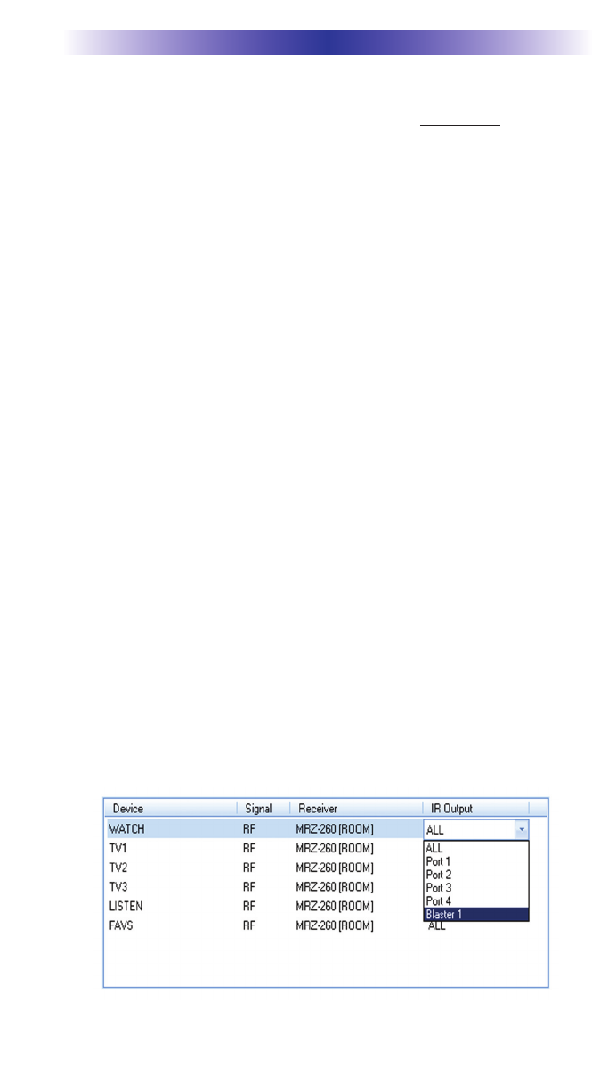
Step 2 - Turn on/off the Front Blaster
Click on the cell in the IR LED OUTPUT/IR BLASTER column. A list box
will appear. Select a PORT for your device or chooose Blaster 1 to turn it
on.
Step 3- Next, click on Save to apply your change.
MRZ-260 BASE STATION
Page 8
Controlling Four Identical Components/Zones
There are several considerations to take into account when you are
installing an MRZ-260 to control an array of identical components:
1. Each identical component must receive IR commands ONLY from a ded-
icated Flasher affixed to its front panel or a rear panel direct IR input.
The SIGNAL of the remote should be set to RF ONLY for each identical
component. IR can still be utilized for other devices in your system!
2. You must note the NUMBER of the Flasher Output you have utilized for
EACH of the identical components.
Identical Components/Zones - Step by Step via PC
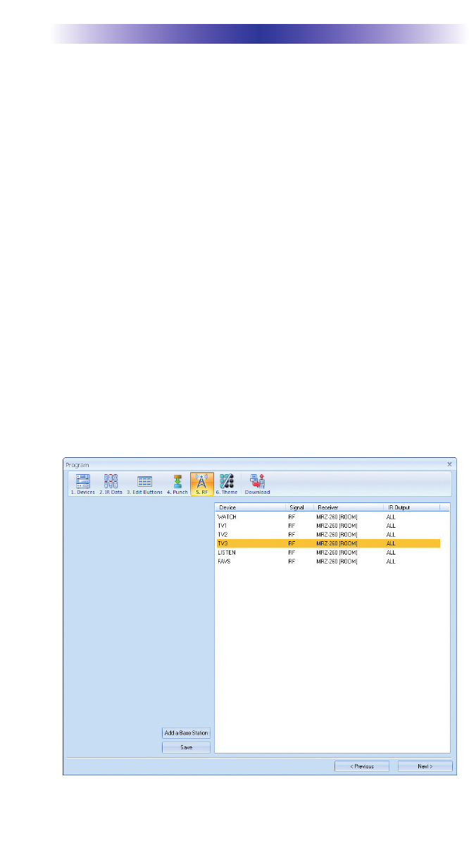
Step 1 - Create and Program a Device for Each Component/Zone
Try to name each device with a descriptive title. At a minimum, label them
TV1, TV2, TV3 and so on.
Step 2 - Open the RF Setup Window
The RF Setup window opens after selecting RF Control from the Program
Menu. The RF Setup window is composed of a “spread sheet” of options for
EACH of your devices.
MRZ-260 BASE STATION
Page 9
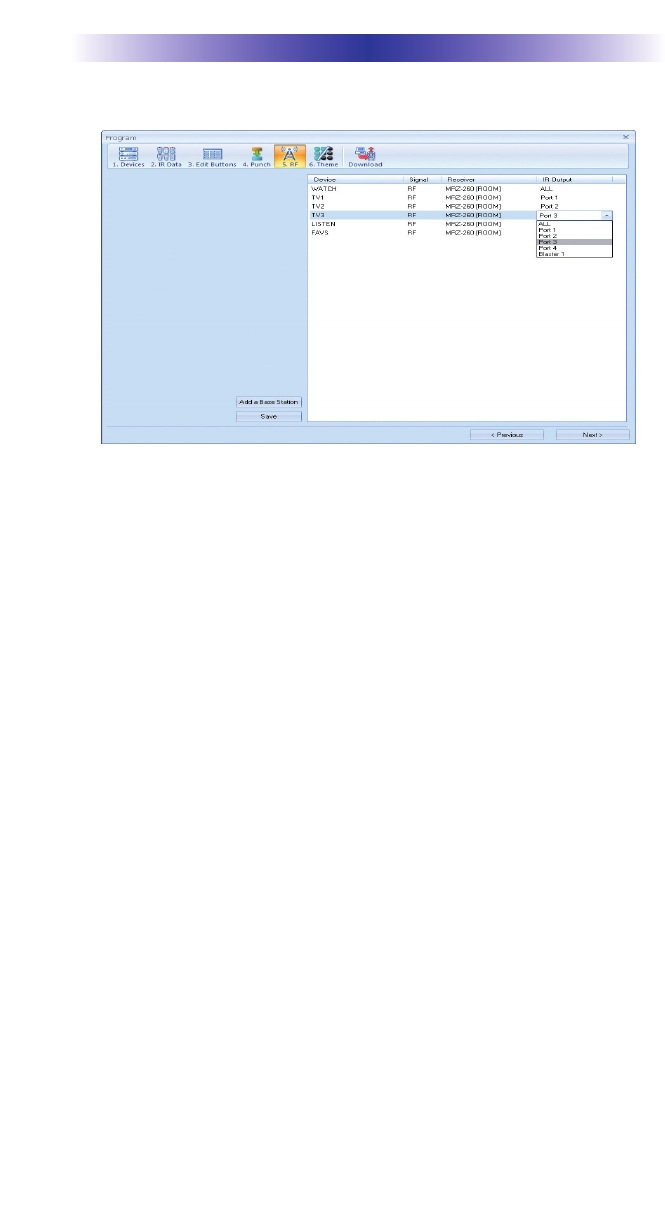
By looking at the Signal column, you can see that the factory default pro-
gramming sets all of the devices to send both IR and RF commands. If you
look at the column for Flashers, you can see that the default sends IR com-
mands for all devices to ALL of the flashers. Both options must be changed
for identical components. Additionally, you must disable the Front Blaster
(see page 6 for directions).
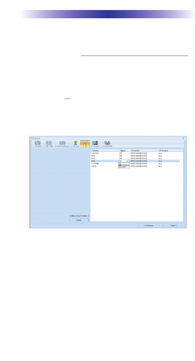
Step 3 - Adjust the Signal For Each of the Identical Devices
The RF Setup window enables you to adjust the Signal output for each
device individually, by clicking on the intersection of a row and a column
and then selecting RF from the three options shown in the pull down list
box.
Select RF from the three options shown for EACH of the identical TVs. You
may leave the other components of the system set to IR & RF.
Step 4 - Adjust the Flashers For Each of the Identical Devices
The RF Setup window enables you to adjust which Flashers output by the
remote control for each device individually, by clicking on the intersection
of a row and a column and then selecting 1-4 from the seven options
shown in the pull down list box.
Select the correct Flasher (refer to your connection notes) for EACH of the
identical TVs. You may leave the other components of the system set to
ALL.
See figure on the next page.
Page 10
MRZ-260 BASE STATION
In the figure below, each device is set to a specific flasher.
Note: Remember, the MRZ-260 will only respond to selections 1 through 4.
Step 5 - Close the RF window and Download to the Remote.
Programming For Multiple Equipment Locations
You can operate an unlimited amount of different equipment locations, each
with an MRZ-260 assigned with a unique MAC Address. You program each
of your remotes to talk to the equipment locations you want by assigning
each of your devices to a receiver. First, you must add and name your
receivers for the locations they are placed in:
Step 1 - Open CCP Editor
This editor will allow you to program multiple base stations.
Step 2 - Click on Program and Configure Home
Step 3 - Add as many MRZ-260 base stations as needed
Follow steps 4 - 11 on page 3 ‘Installation and Discovery’ to automatically
discovery multiple base stations for an unlimited amount of equipment loca-
tions.
Step 4 - Save and Download to your remote.

USA Limited Warranty Statement
Your Universal Remote Control, when delivered to you in new
condition, is warranted against defects in materials or work-
manship as follows: UNIVERSAL REMOTE CONTROL, INC.
warrants this product against defects in material or workman-
ship for a period of one (1) year and as set forth below.
Universal Remote Control will, at its sole option, repair the
product using new or comparable rebuilt parts, or exchange the
product for a comparable new or rebuilt product. In the event
of a defect, these are your exclusive remedies.
This Limited Warranty covers only the hardware components
packaged with the Product. It does not cover technical assis-
tance for hardware or software usage and it does not cover any
software products whether or not contained in the Product; any
such software is provided "AS IS" unless expressly provided for
in any enclosed software Limited Warranty.
To obtain warranty service, you must deliver the product,
freight prepaid, in its original packaging or packaging affording
adequate protection to Universal Remote Control at the address
provided in the Owner's Manual. It is your responsibility to
backup any macro programming, artwork, software or other
materials that may have been programmed into your unit. It is
likely that such data, software, or other materials will be lost
during service and Universal Remote Control will not be
responsible for any such damage or loss. A dated purchase
receipt, Bill of Sale, Installation Contract or other verifiable
Proof of Purchase is required. For product support and other
important information visit Universal Remote Control's website:
http://www.UniversalRemoteControl.com or call the Universal
Remote Control Customer Service Center (914) 835-4484.
This Limited Warranty only covers product issues caused by
defects in material or workmanship during ordinary consumer
use. It does not cover product issues caused by any other rea-
son, including but not limited to product issues due to commer-
cial use, acts of God, third-party installation, misuse, limita-
tions of technology, or modification of or to any part of the
Universal Remote Control product. This Limited Warranty does
not cover Universal Remote Control products sold as USED, AS
IS, REFURBISHED, so-called "B STOCK" or consumables (such
as batteries). This Limited Warranty is invalid if the factory-
applied serial number has been altered or removed from the
product. This Limited Warranty is valid only in the United
States of America. This Limited Warranty specifically excludes
products sold by unauthorized resellers.
MRZ-260 BASE STATION
Page 11

MRZ-260 BASE STATION
Page 12
Frequently Asked Questions
Can I use flasher/emitters that I have already installed in the sys-
tem to connect to the MRZ-260?
Yes, the flashers are compatible if they use 3.5mm mono mini plugs with
the same polarity (Tip is data, sleeve is ground).
I’m getting inconsistent operation regardless of flasher level or
position.
Some components are easily overloaded with IR from nearby flashers.
Prevent IR from affecting the problem component from other flashers or the
front panel blaster by setting the device to a specific IR Line Output instead
of ALL, then adjust the Line Output.
Specifications
Power Supply: 9V 300mA
IR Flasher Line Outputs: 3.5mm Mono Mini Jack
RF Frequency: 2.4GHz

Federal Communication Commission
Interference Statement
This equipment has been tested and found to comply with the limits for a
Class B digital device, pursuant to part 15 of the FCC Rules. These limits are
designed to provide reasonable protection against harmful interference in a
residential installation. This equipment generates, uses and can radiate radio
frequency energy and, if not installed and used in accordance with the instruc-
tions, may cause harmful interference to radio communications. However,
there is no guarantee that interference will not occur in a particular installa-
tion. If this equipment does cause harmful interference to radio or television
reception, which can be determined by turning the equipment off and on, the
user is encouraged to try to correct the interference by one more of the follow-
ing measures:
Reorient or relocate the receiving antenna.
Increase the separation between the equipment and receiver.
Connect the equipment into an outlet on a circuit different from
that to which the receiver is connected.
Consult the dealer or an experienced radio/TV technician for
help.
Warning!
Changes or modifications not expressly approved by the manufacturer could
void the user's authority to operate the equipment.
Note : The manufacturer is not responsible for any Radio or TV interference
caused by unauthorized modifications to this equipment. Such modifications
could void the user's authority to operate the equipment.
FCC Caution
This device complies with Part 15 of the FCC Rules. Operation is subject to the
following two conditions: (1) this device may not cause harmful interference,
and (2) this device must accept any interference received, including interference
that may cause undesired operation.
Any changes or modifications not expressly approved by the party responsible
for compliance could void the authority to operate equipment.
The antenna(s) used for this transmitter must not be co-located or operating in
conjunction with any other antenna or transmitter.
MRZ-260 BASE STATION
Page 13
500 Mamaroneck Avenue, Harrison, NY 10528
Phone: (914) 835-4484 Fax: (914) 835-4532
www.universalremote.com
OCE-0056E Rev.01