Ohsung Electronics URCMSC400 MASTER SYSTEM CONTROLLER User Manual EMISSION TEST REPORT
Ohsung Electronics Co., Ltd. MASTER SYSTEM CONTROLLER EMISSION TEST REPORT
UserManual.wiki
>
Ohsung Electronics
>
URCMSC400 User Manual
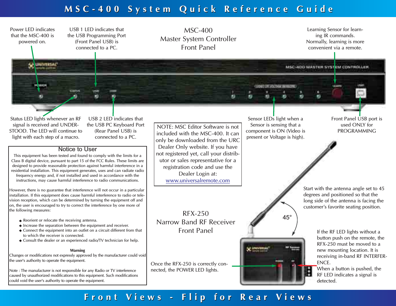
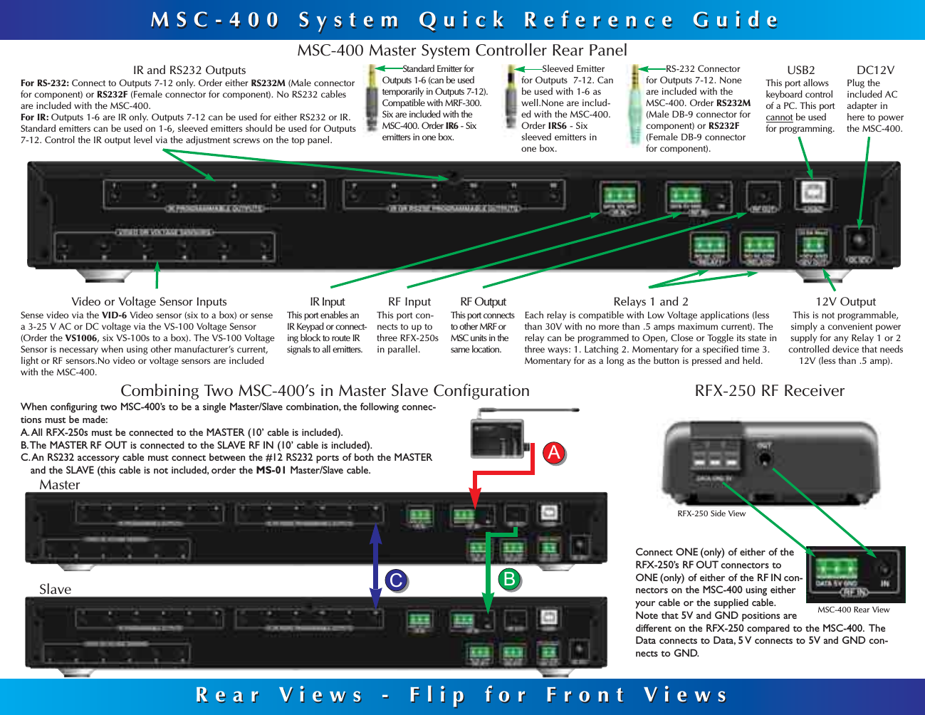
USERS MANUAL
Navigation menu
Upload a User Manual
Namespaces
Wiki Guide
HTML
PDF
Info
Views
User Manual
Discussion / Help
Navigation