Oki Electric Industry 4336821A RFID Module User Manual Module Installation Manual
Oki Data Corporation RFID Module Module Installation Manual
Contents
- 1. Users Manual
- 2. Module Installation Manual
Module Installation Manual
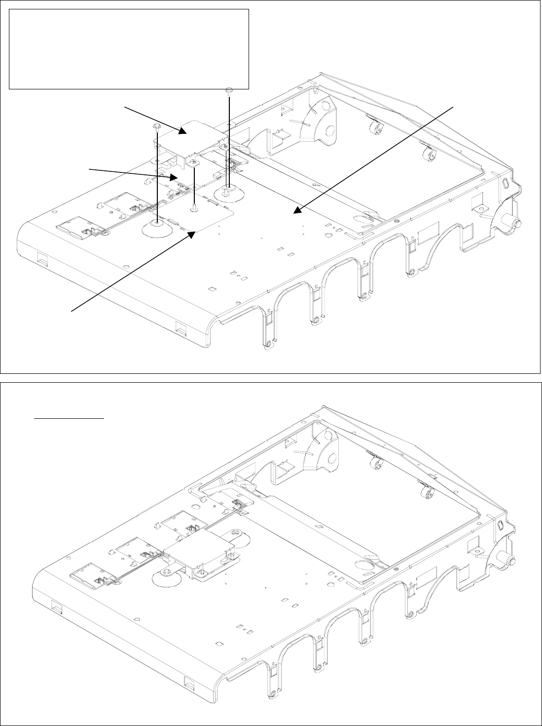
RFID (4336821A) installation procedure.
Plate-Inner
Plate-Shield-RFID
1. To assemble Board-RFID to Plate-Shield-RFID
with two screws.
※RFID Assy – PCB
2. To assemble RFID Assy-PCB to Plate-Inner with
two screws.
Film
Board-RFID
after assembly
※Plate Assy – Inner (4336821A)
A toner cartridge is equipped with RF-ID TAG.
If toner cartridges are set to a printer, communication of RF-ID TAG and a RFID read writer module will be attained.
The function of this system is the following: Management of the existence detection and toner residual quantity of a toner cartridge.
4336821A are attached printer base unit according to the following figure.
RFID (4336821A) installation procedure
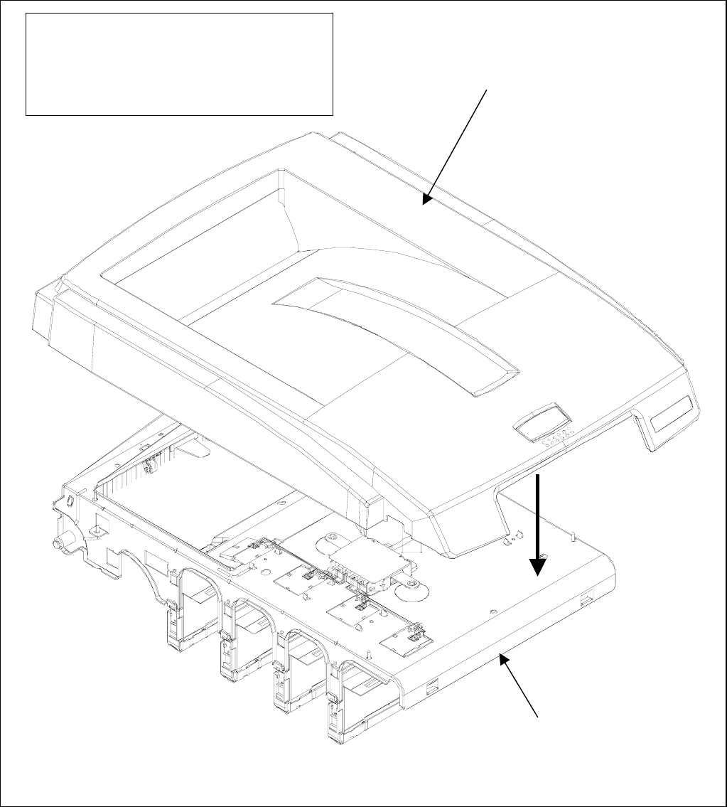
Plate Assy-Inner
(4336821A)
Cover-Top(Sub)
To assemble Head-Cable, Holder-Head,
Cover–Top(Sub) and etc to Plate Assy
–
Inner (4336821A) with 8 screws.
※Cover Assy - Top
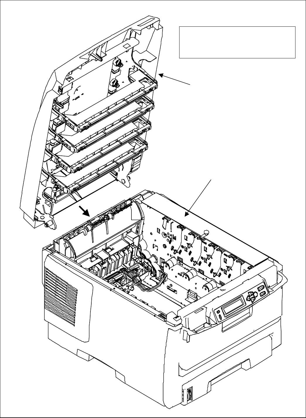
Printer-Unit
Cover Assy - Top
To assemble Cover Assy –Top to
Printer-Unit.
FCC WARNING
Changes or modifications not expressly approved by the party responsible for
compliance could void the user’s authority to operate the equipment.
NOTICE
This equipment has been tested and found to comply with the limits for a Class B digital
device, pursuant to part 15 of the FCC Rules. These limits are designed to provide
reasonable protection against harmful interference in a residential installation.
This equipment generates, uses and can radiate radio frequency energy and, if not
installed and used in accordance with the instructions, may cause harmful interference
to radio communications. However, there is no guarantee that interference will not
occur in a particular installation. If this equipment does cause harmful interference to
radio or television reception, which can be determined by turning the equipment off and
on, the user is encouraged to try to correct the interference by one or more of the
following measures:
-Reorient or relocate the receiving antenna
-Increase the separation between the equipment and receiver.
-Connect the equipment into an outlet on a circuit different from that to which the
receiver is connected.
-Consult the dealer or an experienced radio/TV technician for help.