Olevia 232 S13 User Manual TV LCD Manuals And Guides L0809425
OLEVIA LCD Television Manual L0809425 OLEVIA LCD Television Owner's Manual, OLEVIA LCD Television installation guides
User Manual: Olevia 232-S13 232-S13 OLEVIA TV LCD - Manuals and Guides View the owners manual for your OLEVIA TV LCD #232S13. Home:Electronics Parts:Olevia Parts:Olevia TV LCD Manual
Open the PDF directly: View PDF ![]() .
.
Page Count: 72
TV
TV
2-Series
of Contents
important information t
important Safety Precautions 2
Introducing the OLEVIATV 5
Accessories 7
TV Installation And Connection Guide
identifying Front Controls and Rear Panels 8
- Descriptions of Connector Types i0
= Turn the power on the TV 11
Installation ]2
= Connecting to an Antenna or Video Equipment with Antenna Outlet 13
- Connecting to a Set-Top-Box with HDMI Cables 14
= Connecting to a Satellite Receiver or Cable Box with Component Connectors 15
= Connecting to a DVD Player with A/V or S Video Cables 16
= Connecting to a DVD Player with Component Cables 17
= Connecting to a DVD Player with HDMI Cables lg
= Connecting to a Satellite Receiver or Cable Box with A/V Cables 119
= Connecting to a VCR, PVR, or DV with A/V Cables 20
= Connecting to a Blue=Ray DVD Player or HD=Receiver with HDMI Cables and a
PC with VGACables 2]
- Connecting to a D-VHS with HDMI Cables 22
= Connecting to a D=VHS with Component Cables 23
- Connecting to an Audio Receiver/Home Theater System 24
= OtherAudio Connections 25
- Instruction for Uploading New Firmware 26
Remote Control Guide
= Regular Buttons 27
= Battery Installation 28
On Screen Display (OSD) 29
introduction 29
Operating in the OSD 29
initial Screen 30
PICTURE OSD Adjusting TV Picture Settings 31
= Description of Settings 31
= Selecting the Picture Mode 32
-Adjusting the Picture Quality 33
AUDIO OSD Adjusting Sound Quality 34
= Description of Settings 34
=Adjusting the Audio Settings 34
= MTS System for Stereo TV 35
SCREEN OSD Adjusting Screen Modes 36
= Description of Settings 36
= Changing the Screen Mode 36
-Selecting the Picture/Video Source 3g
SETUP OSD Adjusting Personal TV Settings 39
= Description of Settings 39
= Searching the TV Channels 40
= Editing Channels 4J
-Closed Caption Options 45
= Setting up Parental Control Password 46
=Activating the Parental Control Feature 46
= Resetting the Password 52
=Setting the Date and Time 53
-Setting the TV Timer 54
= Timeout Settings for OSD Menu 54
=TV OSD Languages 55
-Setting DPMS 55
= Setting LED Light 55
= Factory Default Option 55
= Displaying the Firmware Version 55
Specifications 56
Timing Mode for VGA and NDMI(PC) 58
Pixels Policy 59
Glossary 60
Panel Display Mount 65
ortant Information
I 1 "
Risk of electronic shock
Do not open
Toreduce the risk of electronic shock, do not remove cover (or back).
No user-serviceable parts inside.
Refer service to qualified Repair Technician or Repair Center.
Read the following context indicated by the following symbol to the left.
It indicates important literature in operating the product.
Read the following context indicated by the following symbol to the left.
It indicates a potential high voltage hazard that may compromise your safety.
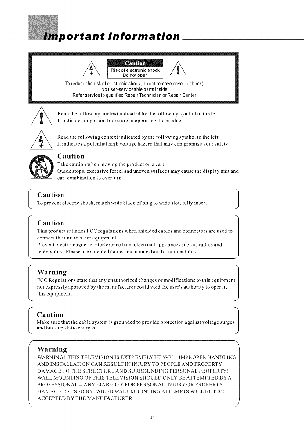
Caution
Take caution when moving the product on a cart.
Quick stops, excessive force, and uneven surfaces may cause the display unit and
cart combination to overturn.
I
Caution
To prevent electric shock, match wide blade of plug to wide slot, fully insert.
Caution 1
This product satisfies FCC regulations when shielded cables and connectors are used to
connect the unit to other equipment.
Prevent electromagnetic interference from electrical appliances such as radios and
televisions. Please use shielded cables and connectors for connections.
Warning
FCC Regulations state that any unauthorized changes or modifications to this equipment[
not expressly approved by the manufacturer could void the user's authority to operate [
this equipment. J
Caution
Make sure that the cable system is grounded to provide protection against voltage surges
and built up static charges.
Warning
WARNING! THIS TELEVISION IS EXTREMELY HEAVY -- IMPROPER HANDLING
AND INSTALLATION CAN RESULT IN INJURY TO PEOPLE AND PROPERTY
DAMAGE TO THE STRUCTURE AND SURROUNDING PERSONAL PROPERTY!
WALL MOUNTING OF THIS TELEVISION SHOULD ONLY BE ATTEMPTED BY A
PROFESSIONAL -- ANY LIABILITY FOR PERSONAL INJURY OR PROPERTY
DAMAGE CAUSED BY FAILED WALL MOUNTING ATTEMPTS WILL NOT BE
ACCEPTED BY THE MANUFACTURER!
J
01
portant Safety Precautions
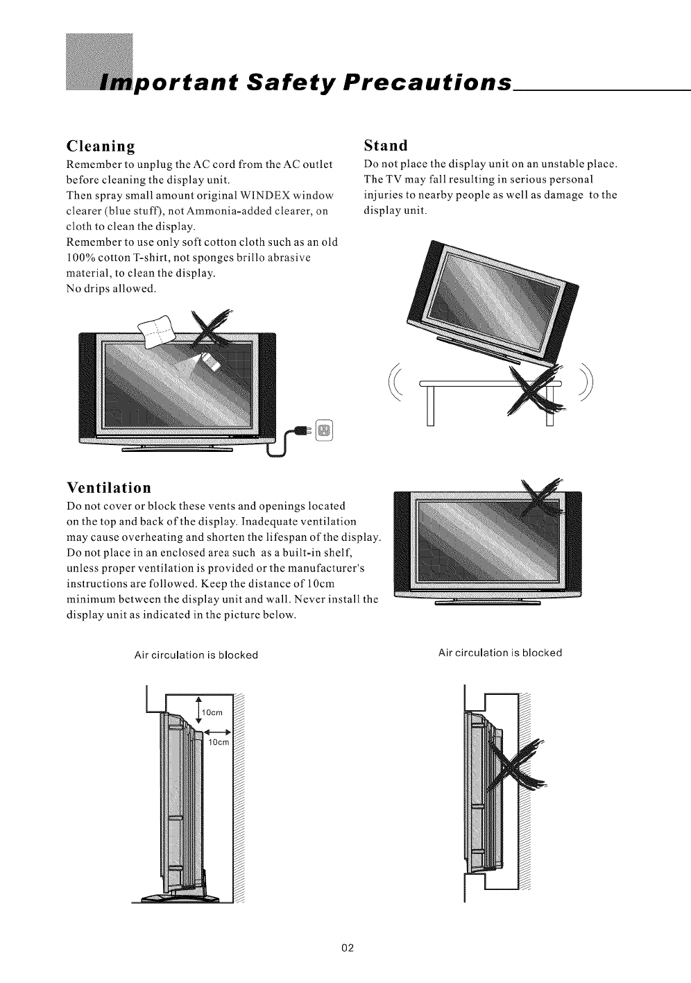
Cleaning
Remember to unplug the AC cord from the AC outlet
before cleaning the display unit.
Then spray small amount original WINDEX window
clearer (blue stuff), not Ammonia-added clearer, on
cloth to clean the display.
Remember to use only soft cotton cloth such as an old
100% cotton T-shirt, not sponges brillo abrasive
material, to clean the display.
No drips allowed.
Stand
Do not place the display unit on an unstable place.
The TV may fall resulting in serious personal
injuries to nearby people as well as damage to the
display unit.
Ventilation
Do not cover or block these vents and openings located
on the top and back of the display. Inadequate ventilation
may cause overheating and shorten the lifespan of the display.
Do not place in an enclosed area such as a built-in shelf,
unless proper ventilation is provided or the manufacturer's
instructions are followed. Keep the distance of 10cm
minimum between the display unit and wall. Never install the
display unit as indicated in the picture below.
Air circulation is blocked Air circulation is blocked
02
ImportantSafetyPrecautions
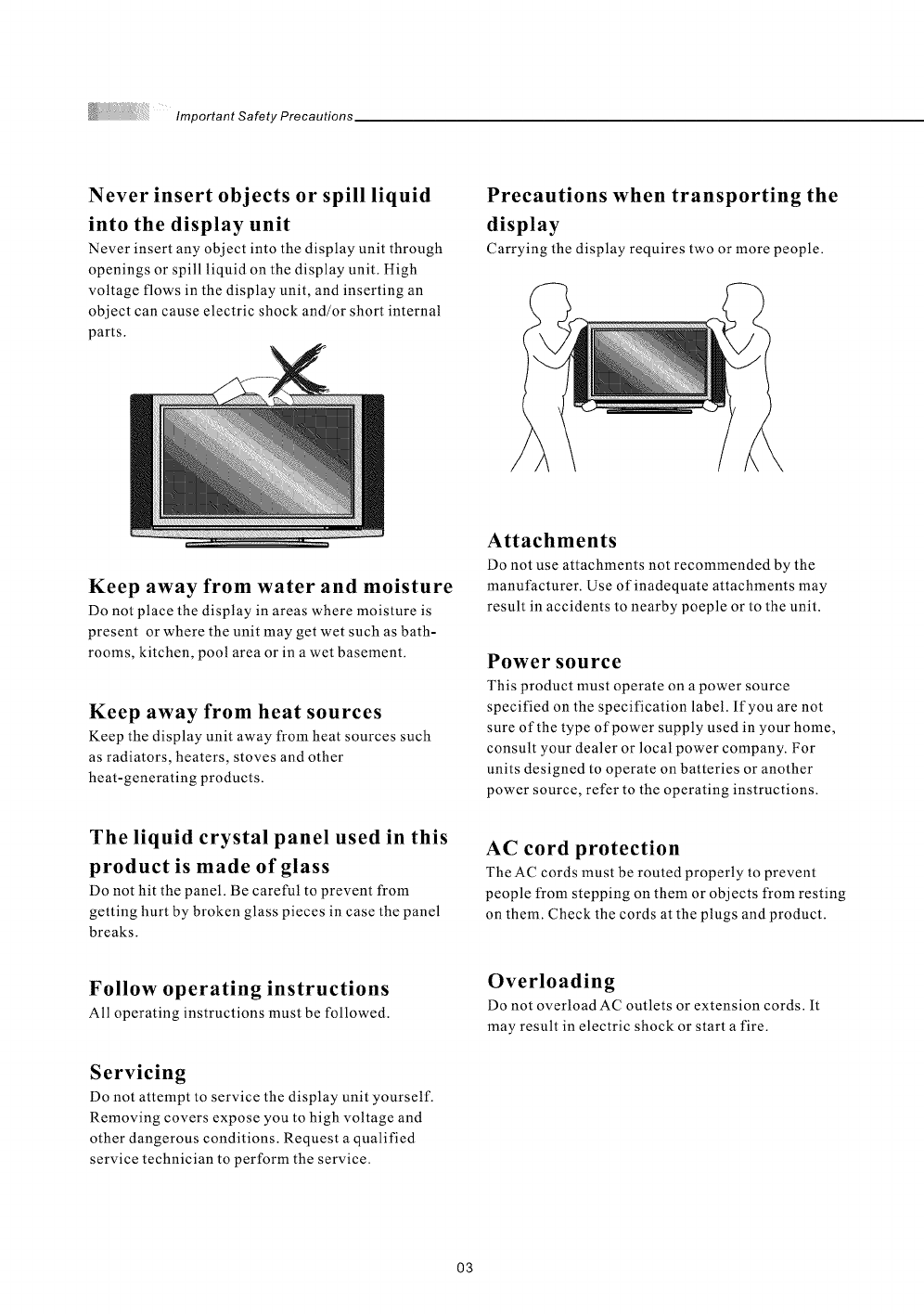
Never insert objects or spill liquid
into the display unit
Never insert any object into the display unit through
openings or spill liquid on the display unit. High
voltage flows in the display unit, and inserting an
object can cause electric shock and/or short internal
parts.
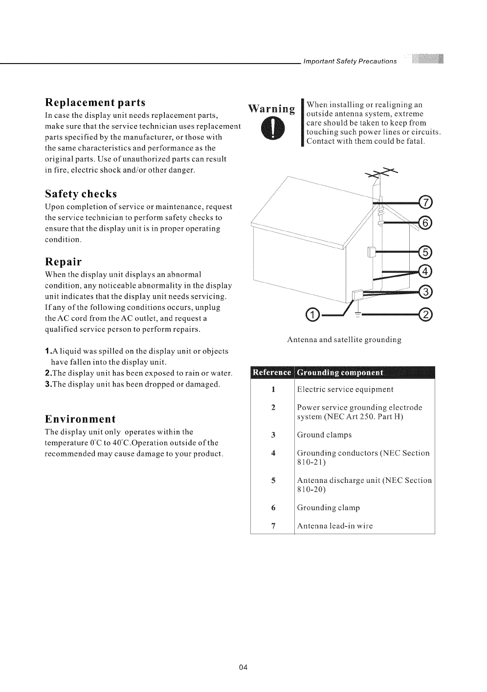
Precautions when transporting the
display
Carrying the display requires two or more people.
Keep away from water and moisture
Do not place the display in areas where moisture is
present or where the unit may get wet such as bath-
rooms, kitchen, pool area or in a wet basement.
Keep away from heat sources
Keep the display unit away from heat sources such
as radiators, heaters, stoves and other
heat-generating products.
The liquid crystal panel used in this
product is made of glass
Do not hit the panel. Be careful to prevent from
getting hurt by broken glass pieces in case the panel
breaks.
Attachments
Do not use attachments not recommended by the
manufacturer. Use of inadequate attachments may
result in accidents to nearby poeple or to the unit.
Power source
This product must operate on a power source
specified on the specification label. If you are not
sure of the type of power supply used in your home,
consult your dealer or local power company. For
units designed to operate on batteries or another
power source, refer to the operating instructions.
AC cord protection
The AC cords must be routed properly to prevent
people from stepping on them or objects from resting
on them. Check the cords at the plugs and product.
Follow operating instructions
All operating instructions must be followed.
Servicing
Do not attempt to service the display unit yourself.
Removing covers expose you to high voltage and
other dangerous conditions. Request a qualified
service technician to perform the service.
Overloading
Do not overload AC outlets or extension cords. It
may result in electric shock or start afire.
O3
Important Safety Precautions
Replacement parts
In case the display unit needs replacement parts,
make sure that the service technician uses replacement
parts specified by the manufacturer, or those with
the same characteristics and performance as the
original parts. Use of unauthorized parts can result
in fire, electric shock and/or other danger.
Safety checks
Upon completion of service or maintenance, request
the service technician to perform safety checks to
ensure that the display unit is in proper operating
condition.
Repair
When the display unit displays an abnormal
condition, any noticeable abnormality in the display
unit indicates that the display unit needs servicing.
If any of the following conditions occurs, unplug
the AC cord from the AC outlet, and request a
qualified service person to perform repairs.
1.A liquid was spilled on the display unit or objects
have fallen into the display unit.
2.The display unit has been exposed to rain or water.
3.The display unit has been dropped or damaged.
Environment
The display unit only operates within the
temperature 0C to 40"C.Operation outside of the
recommended may cause damage to your product.
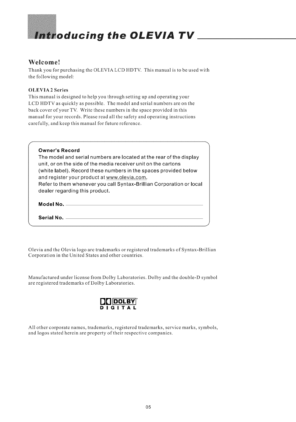
Warning When installing or realigning an
outside antenna system, extreme
care should be taken to keep from
touching such power lines or circuits.
Contact with them could be fatal.
/
/
/
/
©
Antenna and satellite grounding
©
1
2
3
4
6
7
I II I t. I _ 01
Electric service equipment
Power service grounding electrode
system (NEC Art 250. Part H)
Ground clamps
Grounding conductors (NEC Section
810-2t)
Antenna discharge unit (NEC Section
810-20)
Grounding clamp
Antenna lead-in wire
O4
oducing the OLEVIA TV
Welcome!
Thank you for purchasing the OLEVIA LCD HDTV. This manual is to be used with
the following model:
OLEVIA 2 Series
This manual is designed to help you through setting up and operating your
LCD HDTV as quickly as possible. The model and serial numbers are on the
back cover of your TV. Write these numbers in the space provided in this
manual for your records. Please read all the safety and operating instructions
carefully, and keep this manual for future reference.
Owner's Record
The model and serial numbers are located atthe rear of the display
unit, or on the side of the media receiver unit on the cartons
(white label). Record these numbers in the spaces provided below
and register your product at www.olevia.com.
Refer to them whenever you call Syntax-Brillian Corporation or local
dealer regarding this product.
Model No.
Serial No.
Olevia and the Olevia logo are trademarks or registered trademarks of Syntax-Brillian
Corporation in the United States and other countries.
Manufactured under license from Dolby Laboratories. Dolby and the double-D symbol
are registered trademarks of Dolby Laboratories.
I"]["] IDOLBY[°
DIGITAL
All other corporate names, trademarks, registered trademarks, service marks, symbols,
and logos stated herein are property of their respective companies.
O5
Introducing the Syntax-Brillian Olevia TV
OLEVIA LCD HDTV includes many features, you will enjoy throughout
the usage of your TV. These highlighted features include:
Fully Integrated HDTV (High Definition TV):
HDTV delivers a stunning picture far beyond the quality of standard
televisions. These programs offer crystal clear video with amazing
detail played with enhanced audio quality of digital television programs.
You can enjoy better sound and picture in movies, prime time TV shows,
and other HD broadcasts in dynamic television settings through cable,
satellite or even free broadcasts over the air.
HDMI (High Definition Multimedia Interface):
The next generation of DVI, HDMI provides the best interface between
a DVD player and compatible products such as digital set top box for
uncompressed digital audio/video connections. When matched with a
OLEVIA TV, multi-channel digital audio signals, uncompressed DVI digital
video and intercommunication between high multimedia interfaces are
combined through a single interconnecting cable.
HDMI and the HDMI logo are trademarks or registered trademarks of
HDMI Licensing, LLC.
H||| TM
H{GH DEFINITION MULTIMEDIA INTERFACE
ATI:
For a true high definition cinematic experience, your TV uses the Xilleon image
processing chip from ATI. The Xilleon chip offers many advanced features.
The Xilleon chip allows your new TV to display a spectrum of over 16 million
colors, so you can enjoy a true color viewing experience with vivid tones and
natural hues.
Xilleon uses advanced digital image processing technologies to convert
standard definition signals (such as those usually found in analog TV broadcasts,
DVDs, and cable set-top boxes) to the brilliant 1366 x 768 format used by your TV.
With analog video still being broadcast, Xilleon integrates a 3D comb to virtually
eliminate problems like dot crawl and keep your display looking its finest.
Xilleon uses advanced deinterlacing technology to reduce artifacts such as
jagged lines in moving pictures. Contrast, sharpness, saturation and many other
parameters are also automatically optimized 60 times per second.
Enjoy your new TV powered byATI Xilleon.
O6
,cessories
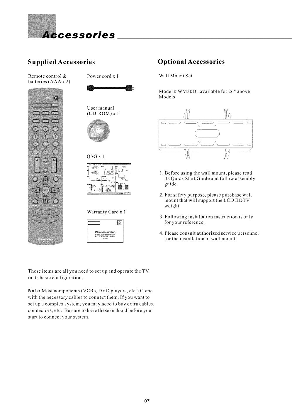
Supplied Accessories
Remote control & Power cord x 1
batteries (AAA x 2) c l
User manual
(CD-ROM) x 1
QSG x 1
Warranty Card x 1
I_l syn_xBrillian _l
........g_r........
Optional Accessories
Wall Mount Set
Model #WM30D : available for 26" above
Models
() c: -_ :> c: .c > c ._ () i
o o
i/° >,
\!J
C:=2? c .............................> c::=:i::_;2_ < ................_ c_<::::::::::::_ c:::_ i
1. Before using the wall mount, please read
its Quick Start Guide and follow assembly
guide.
2. For safety purpose, please purchase wall
mount that will support the LCD HDTV
weight.
3. Following installation instruction is only
for your reference.
4. Please consult authorized service personnel
for the installation of wall mount.
These items are all you need to set up and operate the TV
in its basic configuration.
Note: Most components (VCRs, DVD players, etc.) Come
with the necessary cables to connect them. If you want to
set up a complex system, you may need to buy extra cables,
connectors, etc. Be sure to have these on hand before you
start to connect your system.
07
Installation and Connection Guide
Identifying Front and Rear Panels
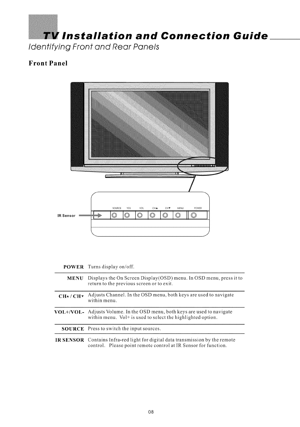
Front Panel
POWER
MENU
CHA /CHv
VOL+/VOL-
SOURCE
IR SENSOR
Turns display on/off.
Displays the On Screen Display(OSD) menu. in OSD menu, press it to
return to the previous screen or to exit.
Adjusts Channel. In the OSD menu, both keys are used to navigate
within menu.
Adjusts Volume. in the OSD menu, both keys are used to navigate
within menu. Vol _ is used to select the highlighted option.
Press to switch the input sources.
Contains Infra-red light for digital data transmission by the remote
control. Please point remote control at IR Sensor for function.
O8
Identifying Front and Rear Panels
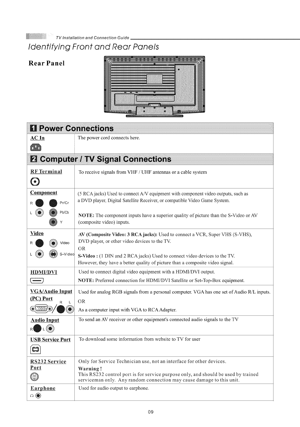
Rear Panel
AC In The power cord connects here.
RF Terminal
®
Component
R 0 OPr/Cr
L (_ @ Pb/Cb
Video
R 0 (_ Video
L (_ @ S-Video
HDMI/DVI
VGA/Audio Input
(PC) Port R L
Audio Input
R®L®
USB Service Port
RS232 Service
Port
Earphone
To receive signals from VHF /UHF antennas or a cable system
(5 RCAjacks) Used to connect A/V equipment with component video outputs, such as
a DVD player, Digital Satellite Receiver, or compatible Video Game System.
NOTE: The component inputs have a superior quality of picture than the S-Video or AV
(composite video) inputs.
AV (Composite Video: 3 RCA jacks): Used to connect a VCR, Super VHS (S-VHS),
DVD player, or other video devices to the TV.
OR
S-Video : (1 DIN and 2 RCA jacks) Used to connect video devices to the TV.
However, they have a better quality of picture than a composite video signal.
Used to connect digital video equipment with a HDMI/DVI output.
NOTE: Preferred connection for HDMI/DVI Satellite or Set-Top-Box equipment.
Used for analog RGB signals from a personal computer. VGA has one set of Audio R/L inputs.
OR
As a computer input with VGA to RCA Adapter.
To send an AV receiver or other equipment's connected audio signals to the TV
To download some information from website to TV for user
Only for Service Technician use, not an interface for other devices.
Warning !
This RS232 control port is for service purpose only, and should be used by trained
serviceman only. Any random connection may cause damage to this unit.
Used for audio output to earphone.
O9
TV Installation and Connection Guide
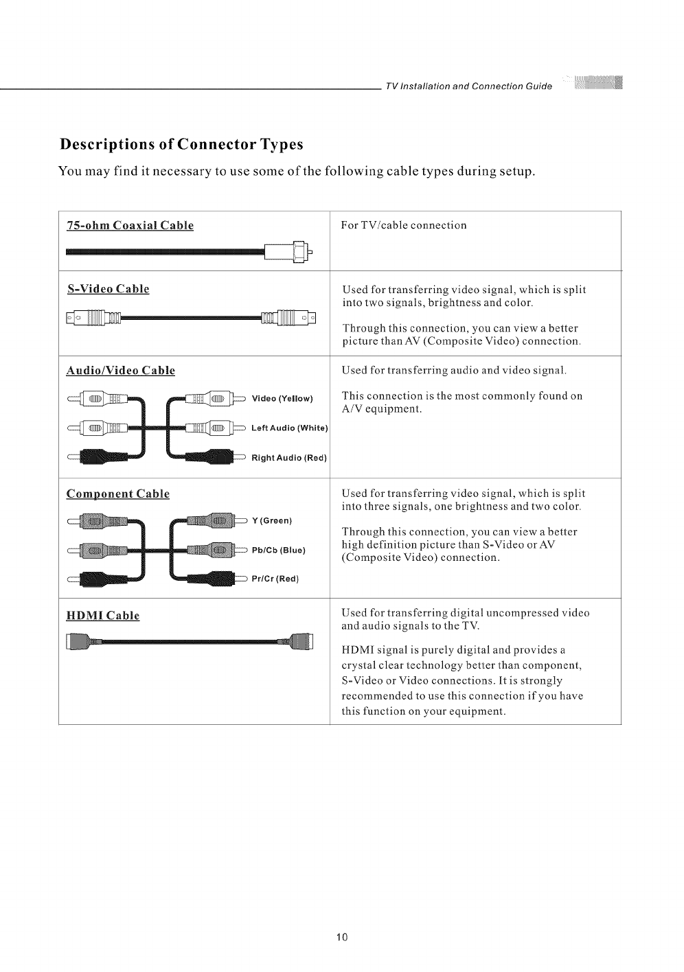
Descriptions of Connector Types
You may find it necessary to use some of the following cable types during setup.
75-ohm Coaxial Cable
S-Video Cable
Audio/Video Cable
Video (Yellow)
Left Audio (White)
Right Audio (Red}
Component Cable
Y(Green)
Pb/Cb (Blue)
Pr/Cr (Red)
HDMI Cable
For TV/cable connection
Used for transferring video signal, which is split
into two signals, brightness and color.
Through this connection, you can view a better
picture than AV (Composite Video) connection.
Used for transferring audio and video signal.
This connection is the most commonly found on
A/V equipment.
Used for transferring video signal, which is split
into three signals, one brightness and two color.
Through this connection, you can view a better
high definition picture than S-Video orAV
(Composite Video) connection.
Used for transferring digital uncompressed video
and audio signals to the TV.
HDMI signal is purely digital and provides a
crystal clear technology better than component,
S=Video or Video connections, it is strongly
recommended to use this connection if you have
this function on your equipment.
10
TVInstallationandConnectionGuide
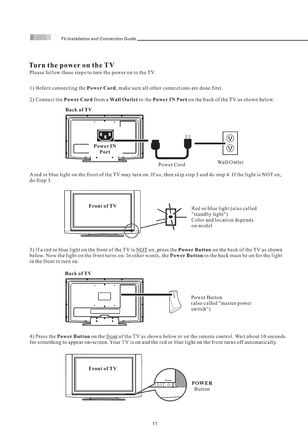
Turn the power on theTV
Please follow these steps to turn the power on to the TV.
1) Before connecting the Power Cord, make sure all other connections are done first.
2) Connect the Power Cord from a Wall Outlet to the Power iN Port on the back of the TV as shown below.
Back of TV
Power IN ]
Port
Power Cord Wall Outlet
A red or blue light on the front of the TV may turn on. lfso, then skip step 3 and do step 4. If the light is NOT on,
do Step 3.
Red or blue light (also called
"standby light").
Color and location depends
on model
3) lfa red or blue light on the front of the TV is NOT on, press the Power Button on the back of the TV as shown
below. Now the light on the front turns on. In other words, the Power Button in the back must be on for the light
in the front to turn on.
Back of TV
Power Button
(also called "master power
switch")
4) Press the Power Button on the front of the TV as shown below or on the remote control. Wait about 10 seconds
for something to appear on-screen. Your TV is on and the red or blue light on the front turns offautomatically.
Front of TV
POWER
Button
11
Installation
TV Installation and Connection Guide
In the following pages, you will find directions on how to install your tv and choice of video equipment.
_ Connecting to an Antenna or Video Equipment with Antenna outlet
_ Connecting to a Set-Top-Box with HDMI Cables (Preferred TV connection)
_ Connecting to a Satellite Receiver or Cable Box with Component Connectors
(Secondary Preferred after HDMI)
_ Connecting to a DVD Player with A/V or S Video Cables
_ Connecting to a DVD Player with Component Cables
_ Connecting to aDVD Player with HDMI Cables
_ Connecting to a Satellite Receiver or Cable Box with A/V Cables
_ Connecting to a VCR, PVR, or DV with A/V Cables
_ Connecting to a Blue-Ray DVD Player or HD-Receiver with HDMI Cables
and a PC with VGA Cables
_Connecting to a D-VHS with HDMI Cables
_ Connecting to a D-VHS with Component Cables
_ Connecting to an Audio Receiver/Home Theater System
_ Other Audio Connections
_ Instruction for Uploading New Firmware
12
TV Installation and Connection Guide
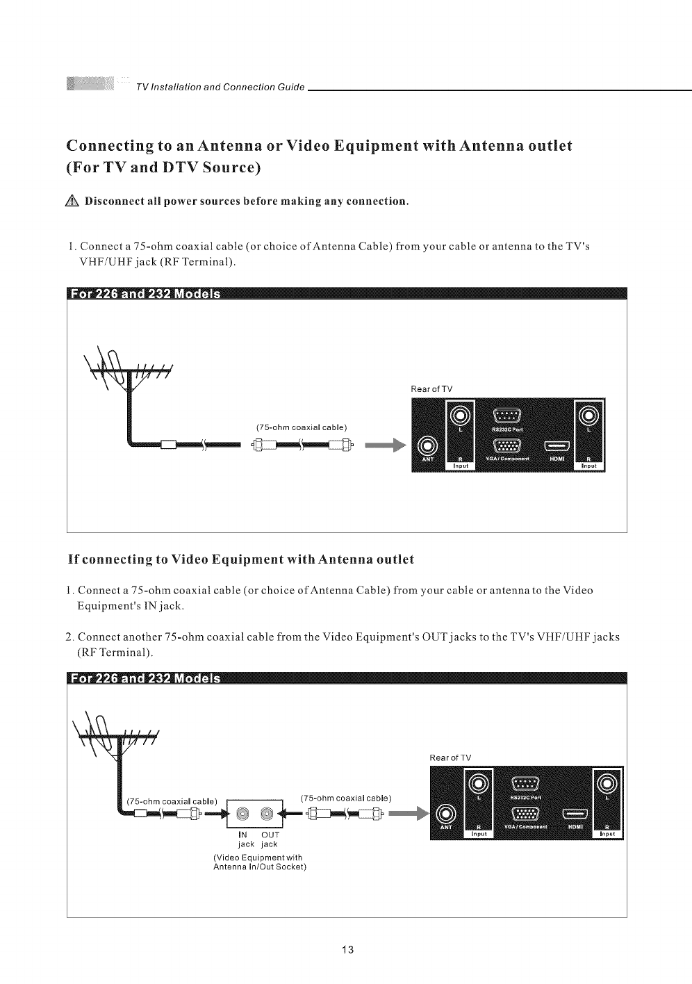
Connecting to an Antenna or Video Equipment with Antenna outlet
(For TV and DTV Source)
Disconnect all power sources before making any connection.
1. Connect a 75-ohm coaxial cable (or choice of Antenna Cable) from your cable or antenna to the TV's
VHF/UHFjack (RF Terminal).
iiiiill....
(75-ohm coaxial cable)
Rear of TV
If connecting to Video Equipment with Antenna outlet
t. Connect a 75-ohm coaxial cable (or choice of Antenna Cable) from your cable or antenna to the Video
Equipment's lNjack.
2. Connect another 75-ohm coaxial cable from the Video Equipment's OUT jacks to the TV's VHF/UttF jacks
(RF Terminal).
y//
(75 ohm coaxial cable)
(75-ohm coaxiamcaMe) Im ' ""
IN OUT
jack jack
(Video Equipment with
Antenna In/Out Socket)
Rear of TV
13
TV Installation and Connection Guide
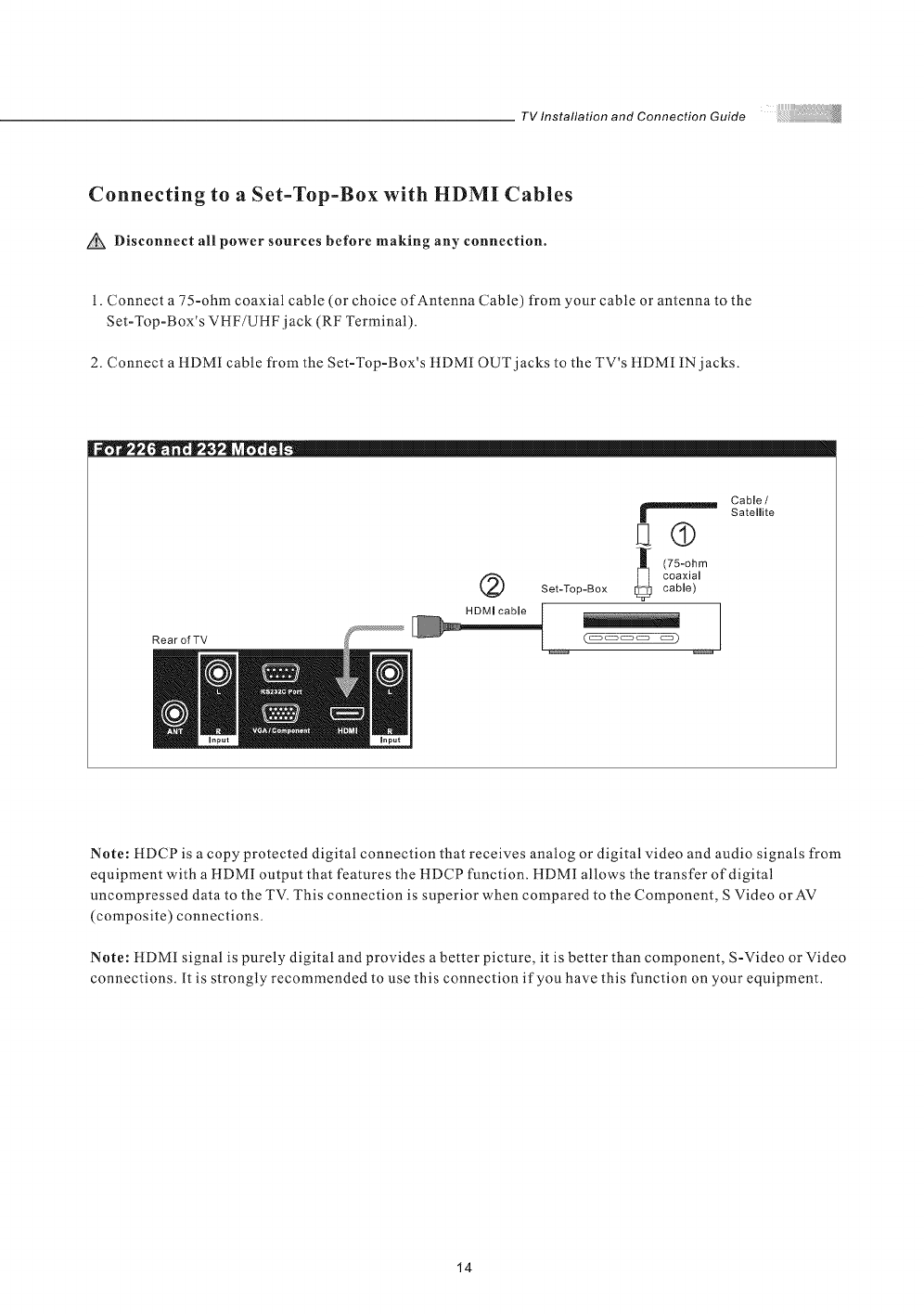
Connecting to a Set-Top-Box with HDMI Cables
Disconnect all power sources before making any connection.
1. Connect a 75-ohm coaxial cable (or choice of Antenna Cable) from your cable or antenna to the
Set-Top-Box's VHF/UHF jack (RF Terminal).
2. Connect a tlDMI cable from the Set-Top-Box's tIDMI OUT jacks to the TV's HDMI IN jacks.
RearofTV
@
Cable /
Satelmite
El®
(75-ohm
coaxial
Set-Top-Box cable)
Note: HDCP is a copy protected digital connection that receives analog or digital video and audio signals from
equipment with a HDMI output that features the HDCP function. HDMI allows the transfer of digital
uncompressed data to the TV. This connection is superior when compared to the Component, S Video orAV
(composite) connections.
Note: tlDMI signal is purely digital and provides a better picture, it is better than component, S-Video or Video
connections. It is strongly recommended to use this connection if you have this function on your equipment.
14
TV Installation and Connection Guide
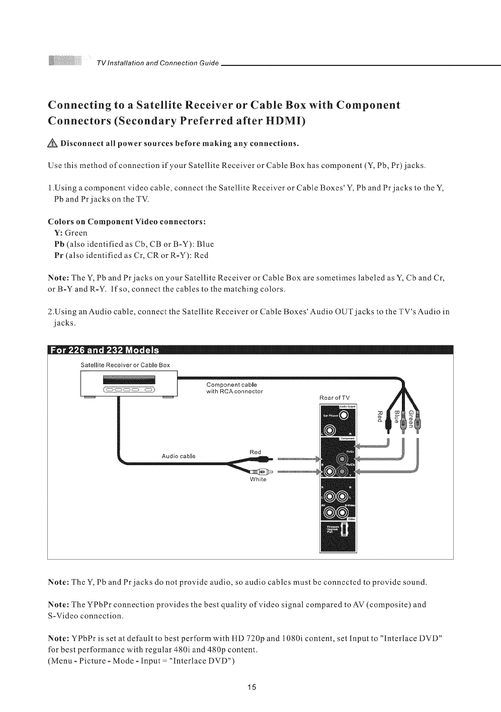
Connecting to a Satellite Receiver or Cable Box with Component
Connectors (Secondary Preferred after HDMI)
Disconnect all power sources before making any connections.
Use this method of connection if your Satellite Receiver or Cable Box has component (Y, Pb, Pr)jacks.
1.Using a component video cable, connect the Satellite Receiver or Cable Boxes' Y, Pb and Pr jacks to the Y,
Pb and Pr jacks on the TV.
CoLors on Component Video connectors:
Y: Green
Pb (also identified as Cb, CB or B-Y): Blue
Pr (also identified as Cr, CR or R-Y): Red
Note: The Y, Pb and Pr jacks on your Satellite Receiver or Cable Box are sometimes labeled as Y, Cb and Cr,
or B-Y and R-Y. lfso, connect the cables to the matching colors.
2.Using an Audio cable, connect the Satellite Receiver or Cable Boxes' Audio OUT jacks to the TV's Audio in
jacks.
[
Satellite Receiver or Cable Box
_ _ I witllRCAconnector RearofTV _
Red
Audio cable
White
Note: The Y, Pb and Pr jacks do not provide audio, so audio cables must be connected to provide sound.
Note: The YPbPr connection provides the best quality of video signal compared to AV (composite) and
S-Video connection.
Note: YPbPr is set at default to best perform with iLD 720p and 1080i content, set input to "Interlace DVD"
for best performance with regular 480i and 480p content.
(Menu -Picture -Mode -Input = "interlace DVD")
15
TV Installation and Connection Guide
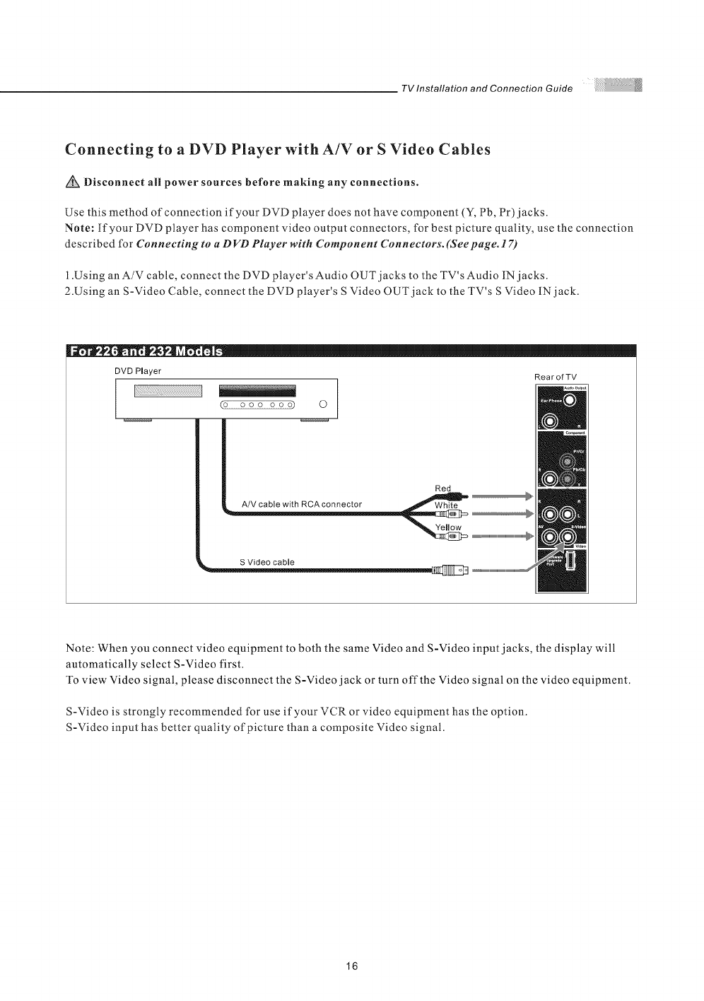
Connecting to a DVD Player with A/V or S Video Cables
Disconnect all power sources before making any connections.
Use this method of connection if your DVD player does not have component (Y, Pb, Pr) jacks.
Note: If your DVD player has component video output connectors, for best picture quality, use the connection
described for Cnnnecting to a D VD Player with Component Connectors. (Seepage. 17)
l .Using an A/V cable, connect the DVD player's Audio OUT jacks to the TV's Audio IN jacks.
2.Using an S-Video Cable, connect the DVD player's S Video OUT jack to the TV's S Video IN jack.
I
DVD Player
£9 ooo oooD 0
RearofTV
Red
i_ A/V cable with RCAcoeeector _ '_"
Note: When you connect video equipment to both the same Video and S-Video input jacks, the display will
automatically select S-Video first.
To view Video signal, please disconnect the S-Video jack or turn off the Video signal on the video equipment.
S-Video is strongly recommended for use if your VCR or video equipment has the option.
S-Video input has better quality of picture than a composite Video signal.
16
TVlnstallationandConnectionGuide
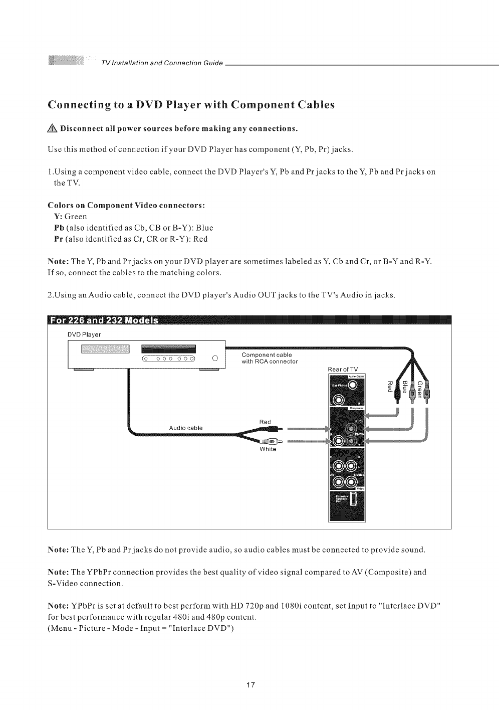
Connecting to a DVD Player with Component Cables
Disconnect all power sources before making any connections.
Use this method of connection if your DVD Player has component (Y, Pb, Pr)jacks.
1.Using a component video cable, connect the DVD Player's Y, Pb and Pr jacks to the Y, Pb and Pr jacks on
the TV.
Colors on Component Video connectors:
V: Green
Pb (also identified as Cb, CB or B-Y): Blue
Pr (a/so identified as Cr, CR or R-Y): Red
Note: The Y, Pb and Pr jacks on your DVD player are sometimes labeled as Y, Cb and Cr, or B-Y and R-Y.
If so, connect the cables to the matching colors.
2.Using an Audio cable, connect the DVD player's Audio OUT jacks to the TV's Audio in jacks.
DVD Player
I
(o ooo ooo)
R0arofTV
Red
White
Note: The Y, Pb and Pr jacks do not provide audio, so audio cables must be connected to provide sound.
Note: The YPbPr connection provides the best quality of video signal compared to AV (Composite) and
S-Video connection.
Note: YPbPr is set at default to best perform with HD 720p and 1080i content, set Input to "interlace DVD"
for best performance with regular 480i and 480p content.
(Menu - Picture - Mode - Input = "Interlace DVD")
17
TV Installation and Connection Guide
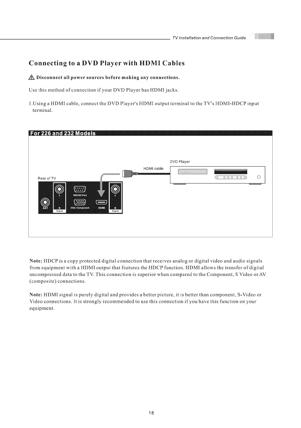
Connecting to a DVD Player with HDMI Cables
Disconnect all power sources before making any connections.
Use this method of connection if your DVD Player has HDMI jacks.
1.Using aHDMI cable, connect the DVD Player's HDMI output terminal to the TV's HDMI-HDCP input
terminal.
RearofTV
DVD Player
(o ooo ooo) 0
Note: HDCP is a copy protected digital connection that receives analog or digital video and audio signals
from equipment with a HDMI output that features the HDCP function. HDMI allows the transfer of digitat
uncompressed data to the TV. This connection is superior when compared to the Component, S Video orAV
(composite) connections.
Note: HDMI signal is purely digital and provides a better picture, it is better than component, S-Video or
Video connections. It is strongly recommended to use this connection if you have this function on your
equipment.
18
TV Installation and Connection Guide
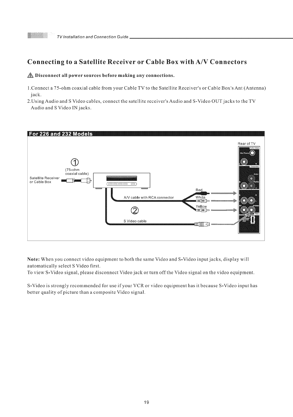
Connecting to aSatellite Receiver or Cable Box with A/V Connectors
Disconnect all power sources before making any connections.
1.Connect a 75-ohm coaxial cable from your Cable TV to the Satellite Receiver's or Cable Box's Ant (Antenna)
jack.
2.Using Audio and S Video cables, connect the satellite receiver's Audio and S-Video OUT jacks to the TV
Audio and S Video IN jacks.
RearofTV
(9
(75-ohm
Satellite Receiver coaxial cable) |
or Cable Box Im_t_l_ /
C coooecto
._ _ _ ...........................................................
|
S Video cable lr I I _"°
Note: When you connect video equipment to both the same Video and S-Video input jacks, display will
automatically select S Video first.
To view S-Video signal, please disconnect Video jack or turn off the Video signal on the video equipment.
S-Video is strongly recommended for use if your VCR or video equipment has it because S-Video input has
better quality of picture than a composite Video signal.
19
TV Installation and Connection Guide
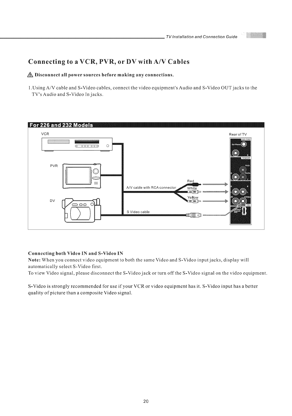
Connecting to a VCR, PVR, or DV with A/V Cables
Disconnect all power sources before making any connections.
i .Using A/V cable and S-Video cables, connect the video equipment's Audio and S-Video OUT jacks to the
TV's Audio and S-Video In jacks.
VCR Rea r of TV
(o ooo ooo) O
PVR
DV
iiii iiiiQI Red
A/V cable with RCAconnector _
Connecting both Video IN and S-Video IN
Note: When you connect video equipment to both the same Video and S-Video input jacks, display will
automatically select S-Video first.
To view Video signal, please disconnect the S-Video jack or turn off the S-Video signal on the video equipment.
S-Video is strongly recommended for use if your VCR or video equipment has it. S-Video input has a better
quality of picture than a composite Video signal.
2O
TV Installation and Connection Guide
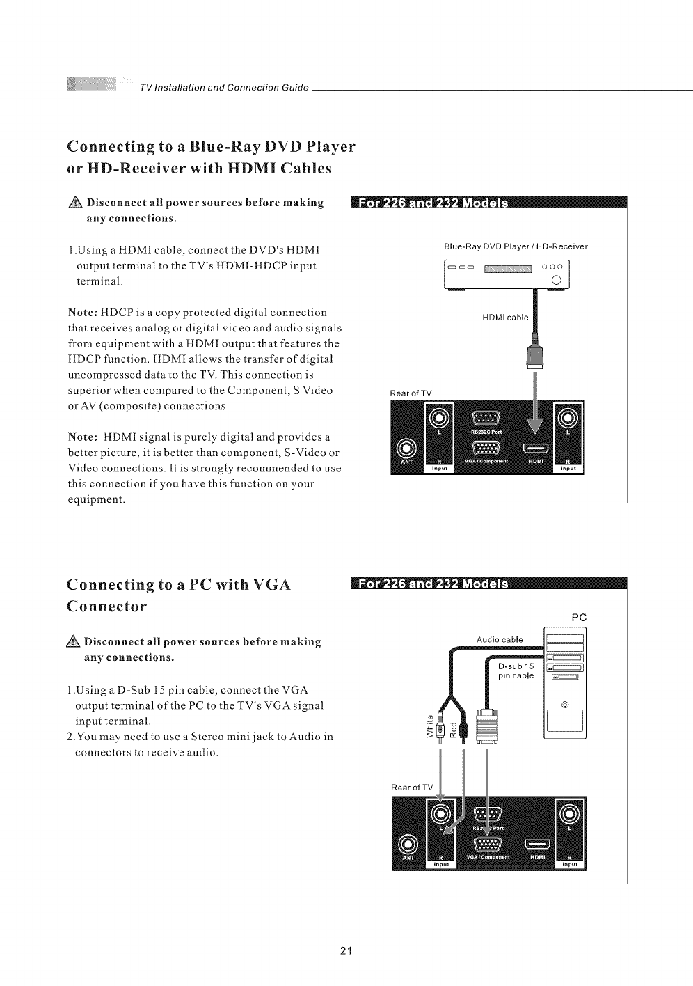
Connecting to a Blue-Ray DVD Player
or HD-Receiver with HDMI Cables
Disconnect all power sources before making
any connections.
1 .Using a HDMI cable, connect the DVD's HDMI
output terminal to the TV's HDMI-HDCP input
terminal.
Note: HDCP is a copy protected digital connection
that receives analog or digital video and audio signals
from equipment with a !tDMI output that features the
HDCP function. HDMI allows the transfer of digital
uncompressed data to the TV. This connection is
superior when compared to the Component, S Video
or AV (composite) connections.
Note: HDMI signal is purely digital and provides a
better picture, it is better than component, S-Video or
Video connections. It is strongly recommended to use
this connection if you have this function on your
equipment.
Blue-Ray DVD Player /HD-Receiver
!2
HDMI cable !
RearofTV
Connecting to a PC with VGA
Connector
Disconnect all power sources before making
any connections.
1 .Using a D-Sub 15 pin cable, connect the VGA
output terminal of the PC to the TV's VGA signal
input terminal.
2.You may need to use a Stereo mini j ack to Audio in
connectors to receive audio.
®,o|* -t_ ll**" !
PC
Audio cable
©
RearofTV
21
TV Installation and Connection Guide
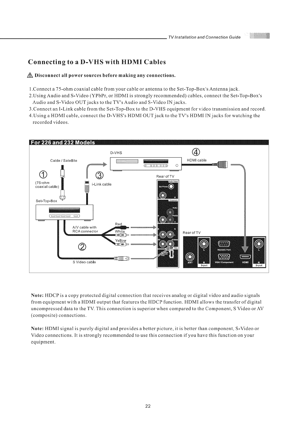
Connecting to a D-VHS with HDMI Cables
Disconnect all power sources before making any connections.
1.Connect a 75-ohm coaxial cable from your cable or antenna to the Set-Top-Box's Antenna jack.
2.Using Audio and S-Video (YPbPr, or tlDMI is strongly recommended) cables, connect the Set-Top-Box's
Audio and S-Video OUT jacks to the TV's Audio and S-Video IN jacks.
3.Connect an I-Link cable from the Set-Top-Box to the D-VHS equipment for video transmission and record.
4.Using a HDM[ cable, connect the D-VHS's HDMI OUT jack to the TV's HDMI IN jacks for watching the
recorded videos.
Cable /Satellite
(75-ohm /
coaxial cable)
Set-Top-Box
| | Red
| _ A/V cable with
S Video cable
D-VHS @
I [ Bo lcable
I
@ R.... fZV
i-Link cable
Rear of TV
Note: HDCP is a copy protected digital connection that receives analog or digital video and audio signals
from equipment with a HDMI output that features the HDCP function. HDMI allows the transfer of digital
uncompressed data to the TV. This connection is superior when compared to the Component, S Video orAV
(composite) connections.
Note: HDMI signal is purely digital and provides a better picture, it is better than component, S-Video or
Video connections. It is strongly recommended to use this connection if you have this function on your
equipment.
22
TV Installation and Connection Guide
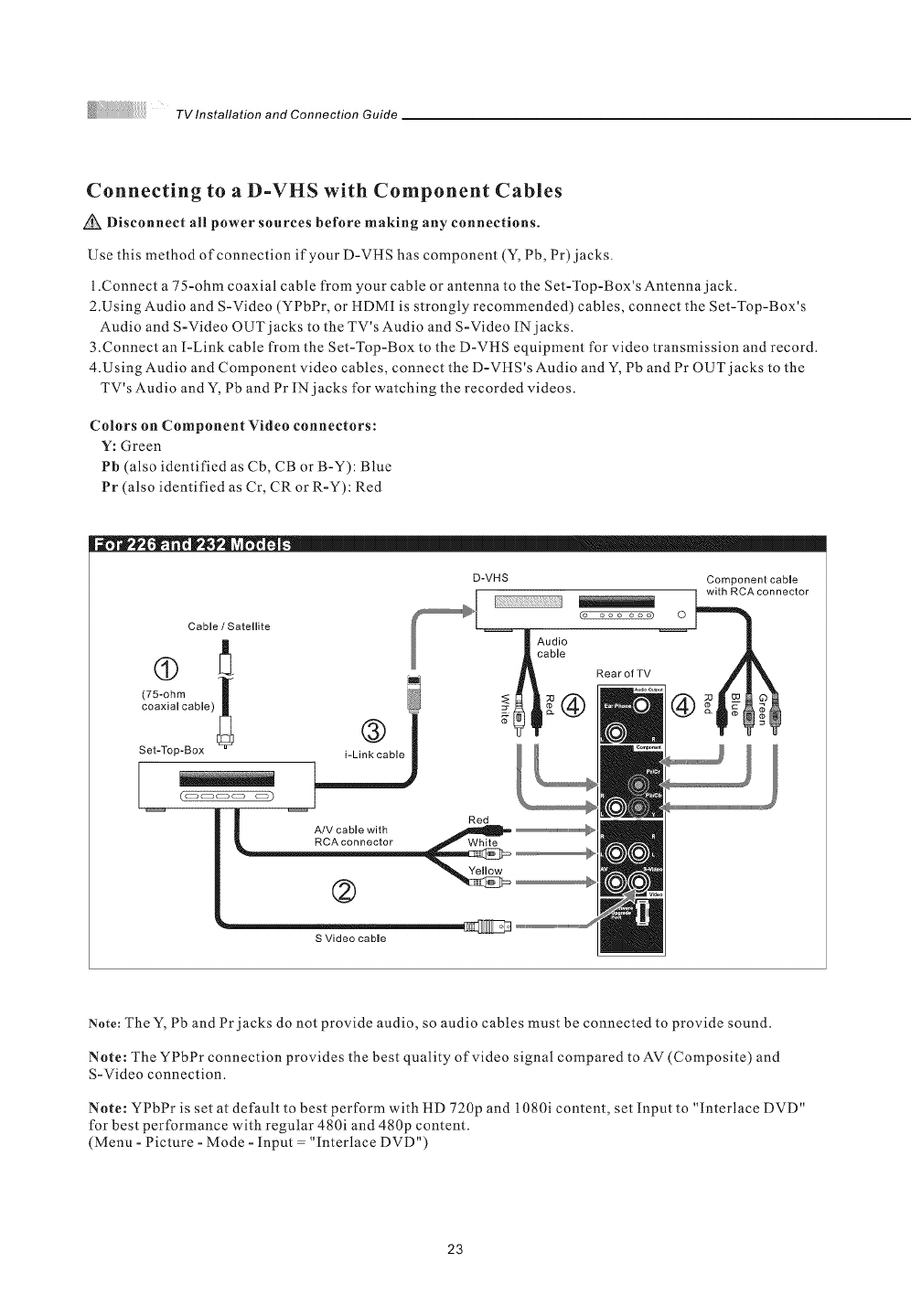
Connecting to a D-VHS with Component Cables
Disconnect all power sources before making any connections.
Use this method of connection if your D-VHS has component (Y, Pb, Pr) jacks.
1 .Connect a 75-ohm coaxial cable from your cable or antenna to the Set-Top-Box's Antenna jack.
2.Using Audio and S-Video (YPbPr, or HDMI is strongly recommended) cables, connect the Set-Top-Box's
Audio and S-Video OUT jacks to the TV's Audio and S-Video IN jacks.
3.Connect an I-Link cable from the Set-Top-Box to the D-VHS equipment for video transmission and record.
4.Using Audio and Component video cables, connect the D-VHS's Audio and Y, Pb and Pr OUT jacks to the
TV's Audio and Y, Pb and Pr IN jacks for watching the recorded videos.
Colors on Component Video connectors:
Y: Green
Pb (also identified as Cb, CB or B-Y): Blue
Pr (also identified as Cr, CR or R-Y): Red
[[iill....
Note: The Y, Pb and Pr jacks do not provide audio, so audio cables must be connected to provide sound.
Note: The YPbPr connection provides the best quality of video signal compared to AV (Composite) and
S-Video connection.
Note: YPbPr is set at default to best perform with HD 720p and 1080i content, set Input to "Interlace DVD"
for best performance with regular 480i and 480p content.
(Menu - Picture - Mode - Input = "Interlace DVD")
23
TV Installation and Connection Guide
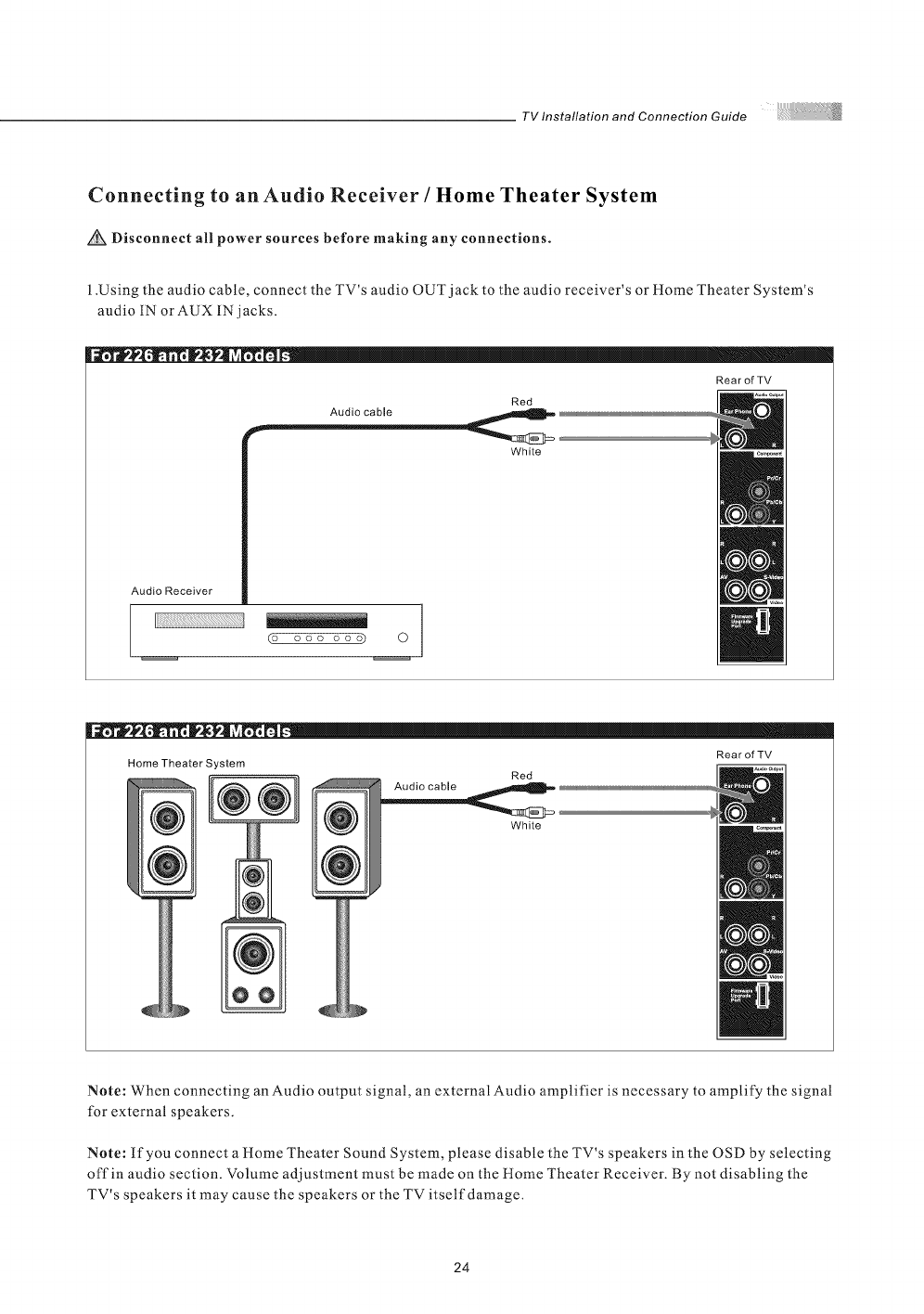
Connecting to an Audio Receiver /Home Theater System
Disconnect all power sources before making any connections.
l.Using the audio cable, connect the TV's audio OUT jack to the audio receiver's or Home Theater System's
audio IN or AUX IN jacks.
Audio Receiver
(o ooo ooo) 0
White
Home Theater System
@Audio cable Red
White
RearofTV
Note: When connecting an Audio output signal, an external Audio amplifier is necessary to amplify the signal
for external speakers.
Note: If you connect a Home Theater Sound System, please disable the TV's speakers in the OSD by selecting
offin audio section. Volume adjustment must be made on the Home Theater Receiver. By not disabling the
TV's speakers it may cause the speakers or the TV itself damage.
24
TVInstallationandConnectionGuide
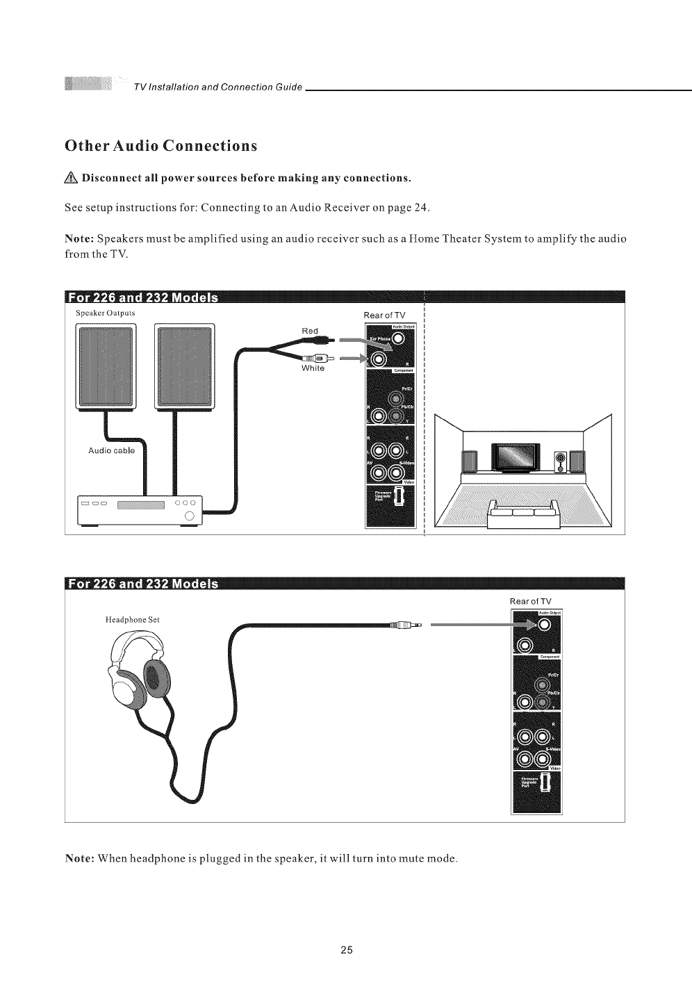
Other Audio Connections
Disconnect all power sources before making any connections.
See setup instructions for: Connecting to an Audio Receiver on page 24.
Note: Speakers must be amplified using an audio receiver such as a Home Theater System to amplify the audio
from the TV.
JJJJll....
Speaker Outputs Rear of TV
Red
White
Audio cable
lliiii,,....
RearofTV
lleadphone Set
Note: When headphone is plugged in the speaker, it will turn into mute mode.
25
TV Installation and Connection Guide
Instruction for Uploading New Firmware
1.Go to our website : www.olevia.com and register TV.
2.Click FutureProof(TM) your TV. You will need the serial number of your Olevia TV and a USB flash drive.
3 .Click on the instructions for your particular model of Olevia TV.
4.Follow the instructions on the website for your specific model to download the new firmware and to load the
firmware into the TV.
26
,mote Control Guide
Remote Function Keys & Description
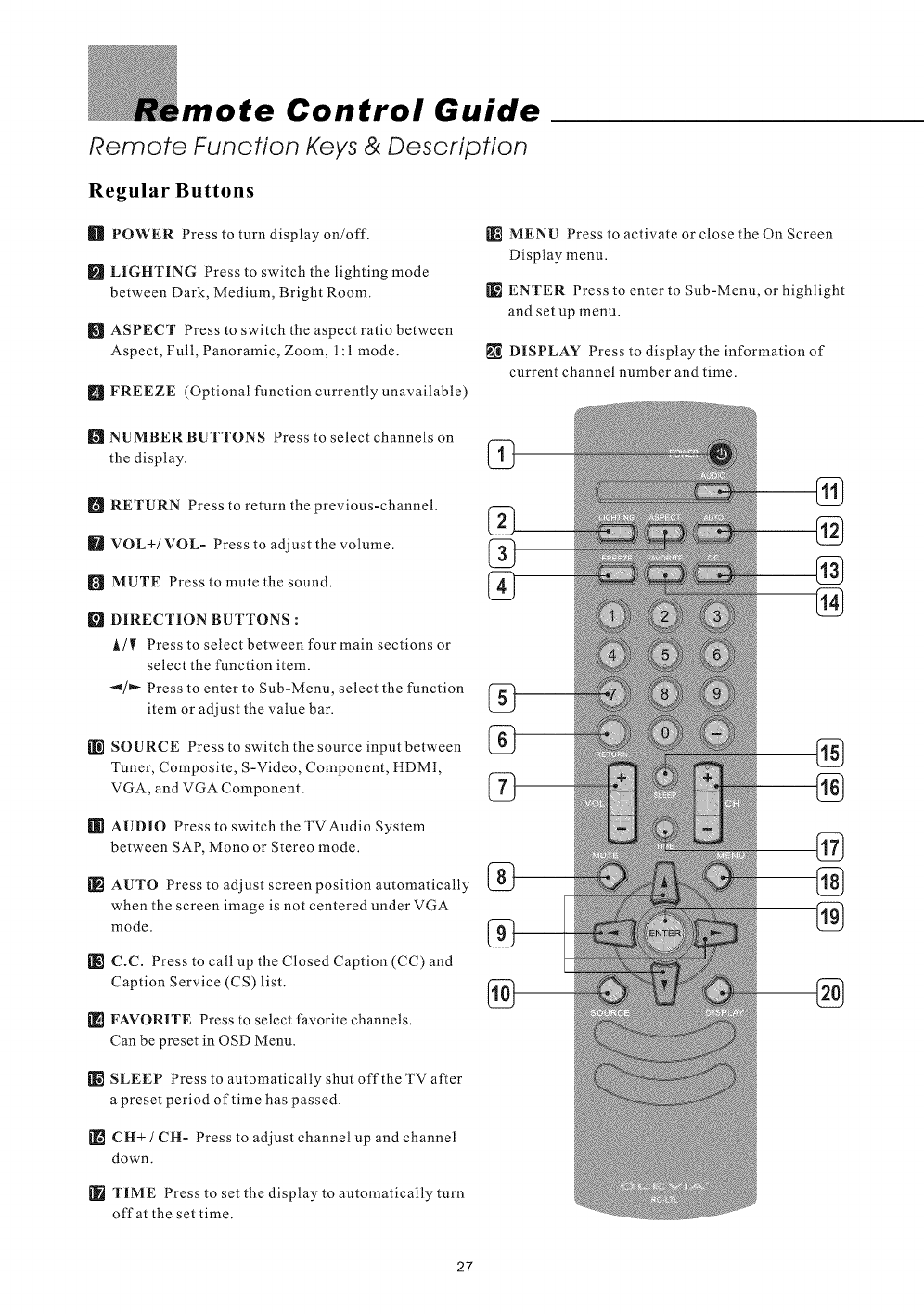
Regular Buttons
_]_ POWER Press to turn display on/off.
[] LIGHTING Press to switch the lighting mode
between Dark, Medium, Bright Room.
ASPECT Press to switch the aspect ratio between
Aspect, Full, Panoramic, Zoom, 1:1 mode.
[] FREEZE (Optional function currently unavailable)
[_ NUMBER BUTTONS Press to select channels on
the display.
[] RETURN Press to return the previous-channel.
IFt VOL+/VOL- Press to adjust the volume.
[_ MUTE Press to mute the sound.
[] DIRECTION BUTTONS :
A/I_ Press to select between four main sections or
select the function item.
"_/_ Press to enter to Sub-Menu, select the function
item or adjust the value bar.
[_ SOURCE Press to switch the source input between
Tuner, Composite, S-Video, Component, HDMI,
VGA, and VGA Component.
[[[I AUDIO Press to switch the TVAudio System
between SAP, Mono or Stereo mode.
[_ AUTO Press to adjust screen position automatically
when the screen image is not centered under VGA
mode.
[_ C.C. Press to call up the Closed Caption (CC) and
Caption Service (CS) list.
_] FAVORITE Press to select favorite channels.
Can be preset in OSD Menu.
[_ SLEEP Press to automatically shut offthe TV after
a preset period of time has passed.
[] CH+ /CH- Press to adjust channel up and channel
down.
TIME Press to set the display to automatically turn
off at the set time.
MENU Press to activate or close the On Screen
Display menu.
ENTER Press to enter to Sub-Menu, or highlight
and set up menu.
DISPLAY Press to display the information of
current channel number and time.
27
Remote Control Guide
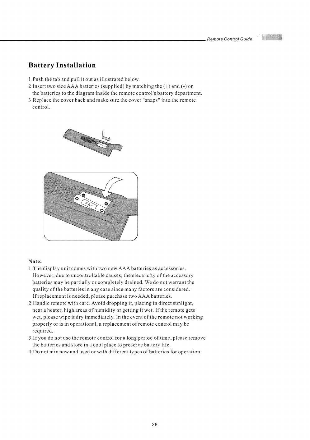
Battery Installation
1.Push the tab and pull it out as illustrated below.
2.Insert two size AAA batteries (supplied) by matching the (+) and (-) on
the batteries to the diagram inside the remote control's battery department.
3 .Replace the cover back and make sure the cover "snaps" into the remote
control.
Note:
1.The display unit comes with two new AAA batteries as accessories.
However, due to uncontrollable causes, the electricity of the accessory
batteries may be partially or completely drained. We do not warrant the
quality of the batteries in any case since many factors are considered.
If replacement is needed, please purchase two AAA batteries.
2.Handle remote with care. Avoid dropping it, placing in direct sunlight,
near a heater, high areas of humidity or getting it wet. If the remote gets
wet, please wipe it dry immediately. In the event of the remote not working
properly or is in operational, a replacement of remote control may be
required.
3 .If you do not use the remote control for a long period of time, please remove
the batteries and store in a cool place to preserve battery life.
4.Do not mix new and used or with different types of batteries for operation.
28
Screen Displays (OSD)
After you have finished connecting your TV, you are now ready to choose
and personalize your TV settings in the OSD (On Screen Display) menu.
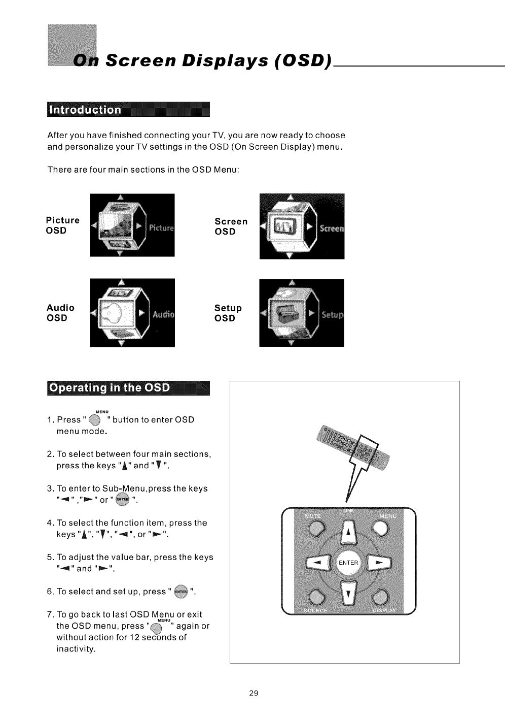
There are four main sections in the OSD Menu:
Picture
OSD Screen
OSD
Audio
OSD Setup
OSD
e= = ." _ j == •|
•_'"_,,
1 Press" button to enter OSD
menu mode.
2. To select between four main sections,
press the keys"A" and "T "
3. To enter to Sub-Menu,press the keys
"4 " ,"D =_ "or "_ "
4. To select the function item, press the
keys "A", "T", "_,1", or "=_".
5. To adjust the value bar, press the keys
"<1" and "l_,_".
6. To select and set up, press " _".
7. To go back to last OSD Menu or exit
M_NU
,@ ,
the OSD menu, press' ' again or
without action for ] 2 seconds of
inactivity.
29
On Screen Displays (OSD)
| _. i = = |
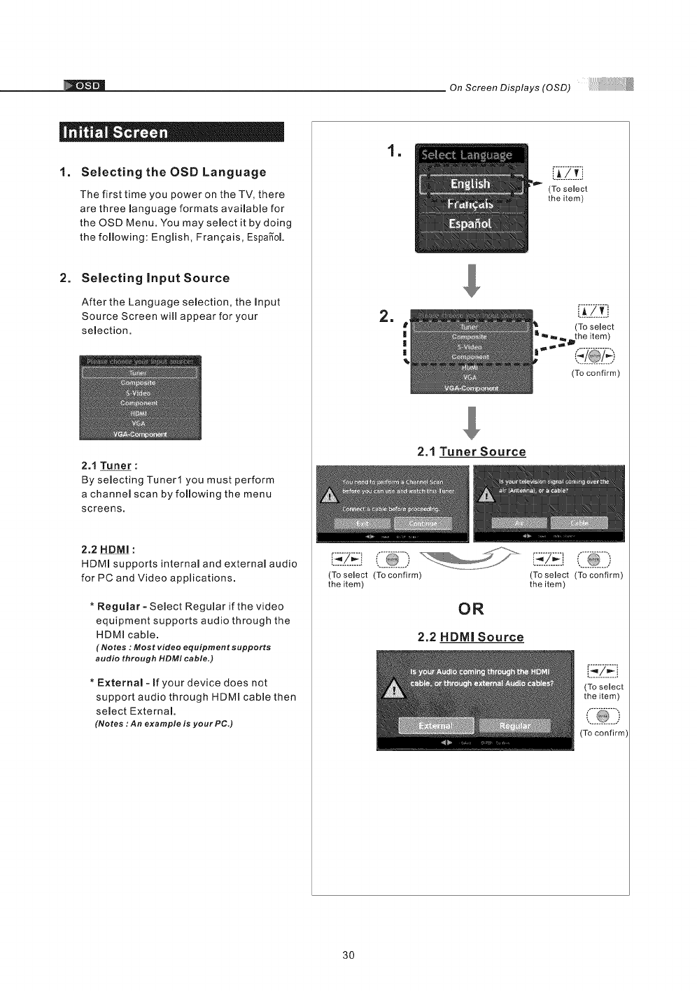
1. Selecting the OSD Language
The first time you power on the TV, there
are three manguage formats avaimable for
the OSD Menu. You maysemect it by doing
the following: Engmish, Fran_ais, EspaS"oL
2. Selecting input Source
After the Language selection, the input
Source Screen will appear for your
semection.
2.1 Tuner :
By selecting Tuner1 you must perform
a channel scan by following the menu
screens.
2.2 HDMI :
HDMm supports internam and externam audio
for PC and Video applications.
* Regular - Semect Regumar if the video
equipment supports audio through the
HDMI cable.
(Notes : Most video equipment supports
audio through HDMI cable,)
* External- if your device does not
support audio through HDMI cable then
semect External
(Notes :An example is your PC.)
!
2.1 Tuner Source
(To select (To confirm)
the item)
OR
2.2 HDMI Source
L.k!._£
(To select
the item)
(To select
,_the item)
(To confirm)
[ Z#ii
(To select (To confirm)
the item)
(To select
the item)
30
On Screen Displays (OSD)
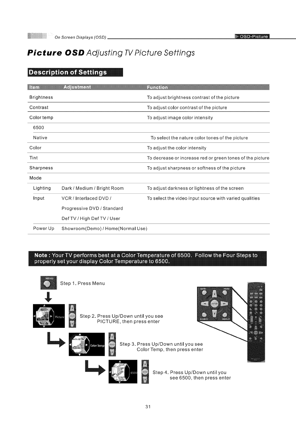
Picture OSD Adjusting TV Picture Settings
|- o o I e " i_.
Brightness To adjust brightness contrast of the picture
Contrast To adjust comor contrast of the picture
Color temp To adjust image color intensity
6500
Native To select the nature color tones of the picture
Comor To adjust the comor intensity
Tint To decrease or increase red or green tones of the picture
Sharpness To adjust sharpness or softness of the picture
Mode
Lighting Dark /Medium /Bright Room To adjust darkness or lightness of the screen
Input VCR /Interlaced DVD /To select the video input source with varied qualities
Progressive DVD /Standard
DefTV /High DefTV/User
Power Up Showroom(Demo) /Home(Normal Use)
Step 1. Press Menu
Step 2. Press Up/Down until you see
PICTURE, then press enter
Step 3. Press Up/Down until you see
Color Temp, then press enter
Step 4. Press Up/Down until you
see 6500, then press enter
31
On Screen Displays (OSD)
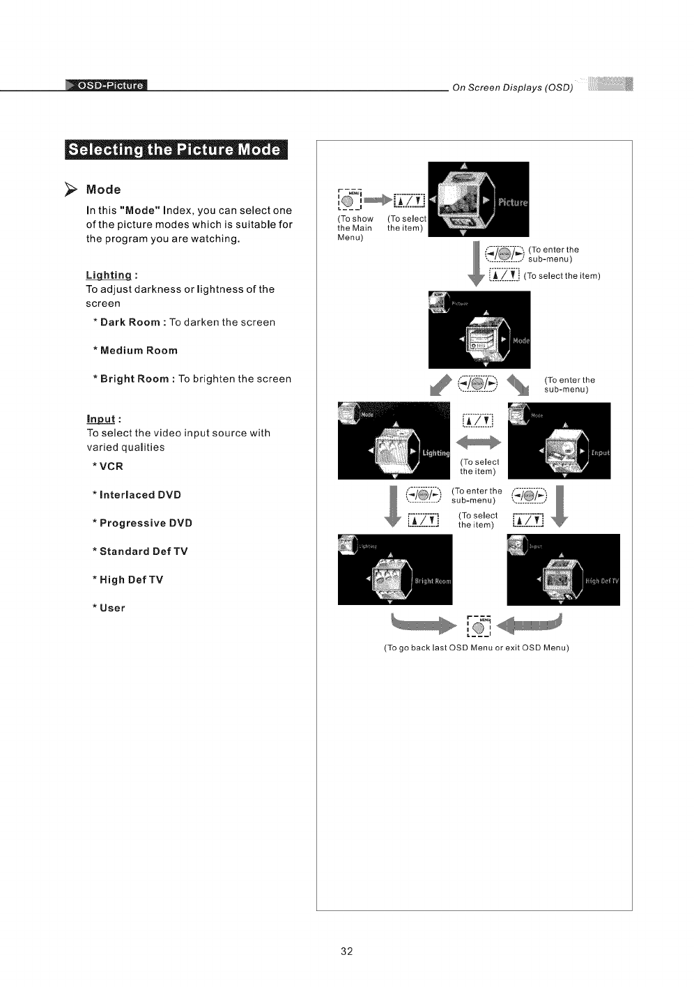
Mode
In this "Mode" Index, you can select one
of the picture modes which is suitable for
the program you are watching.
To adjust darkness or lightness of the
screen
*Dark Room : To darken the screen
*Medium Room
*Bright Room : To brighten the screen
To select the video input source with
varied qualities
* VCR
* interlaced DVB
* Progressive DVD
* Standard Def TV
* High Def TV
* User
(To show
the Main
Menu)
(To select
the item)
,I@1... (To enter the
sub-menu)
(To select
the item)
(_'/_'/_) (To enter the (_7_!
.............. sub-menu) .............
rA7_I (To select .............
............. the item) L_: ,/',:Zi
i i
(To go beck lest OSD Menu or exit OSD Menu)
32
OnScreenDisplays(OSD)
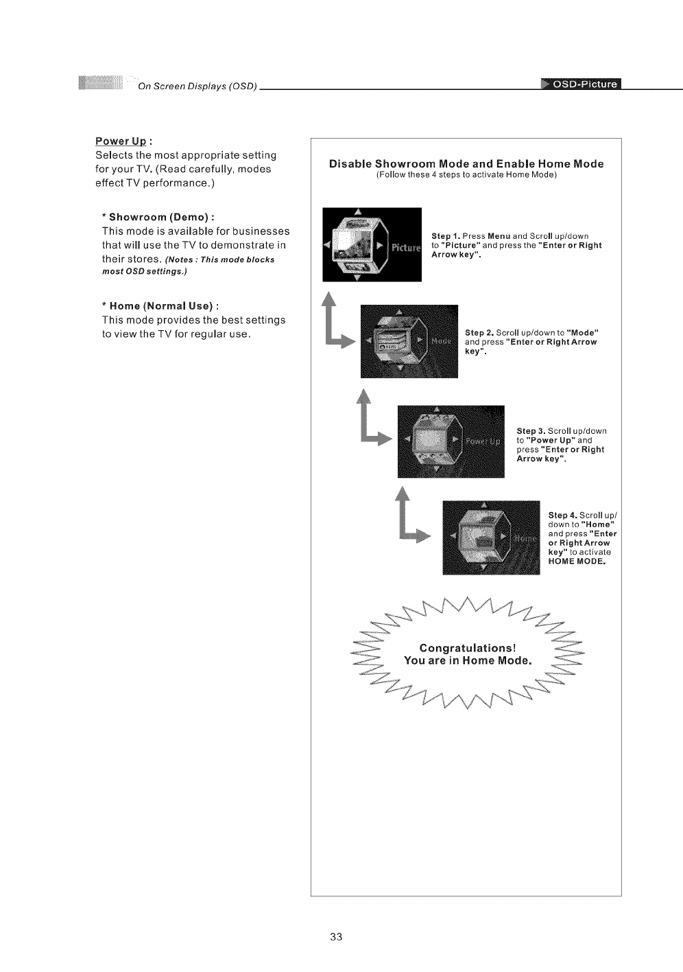
Power _:
Selects the most appropriate setting
for your TV. (Read carefully, modes
effect TV performance.)
*Showroom (Demo) :
This mode is available for businesses
that will use the TVto demonstrate in
their stores. (Notes :This mode blocks
most OSD settings,)
* Home (Normal Use) :
This mode provides the best settings
to view the TV for regular use.
Disable Showroom Mode and Enable Home Mode
(Follow these 4 steps to activate Home Mode)
Step I. Press Menu and Scroll up/down
to "Picture" and press the "Enter or Right
Arrow key".
Step 2. Scroll up/down to "Mode"
and press "Enter or Rig ht Arrow
key".
Step 3. Scroll up/down
to "Power Up" and
press "Enter or Right
Arrow key".
Step 4. Scroll up/
down to "Home"
and press "Enter
or Right Arrow
key" to activate
HOME MODE.
33
On Screen Displays (OSD)
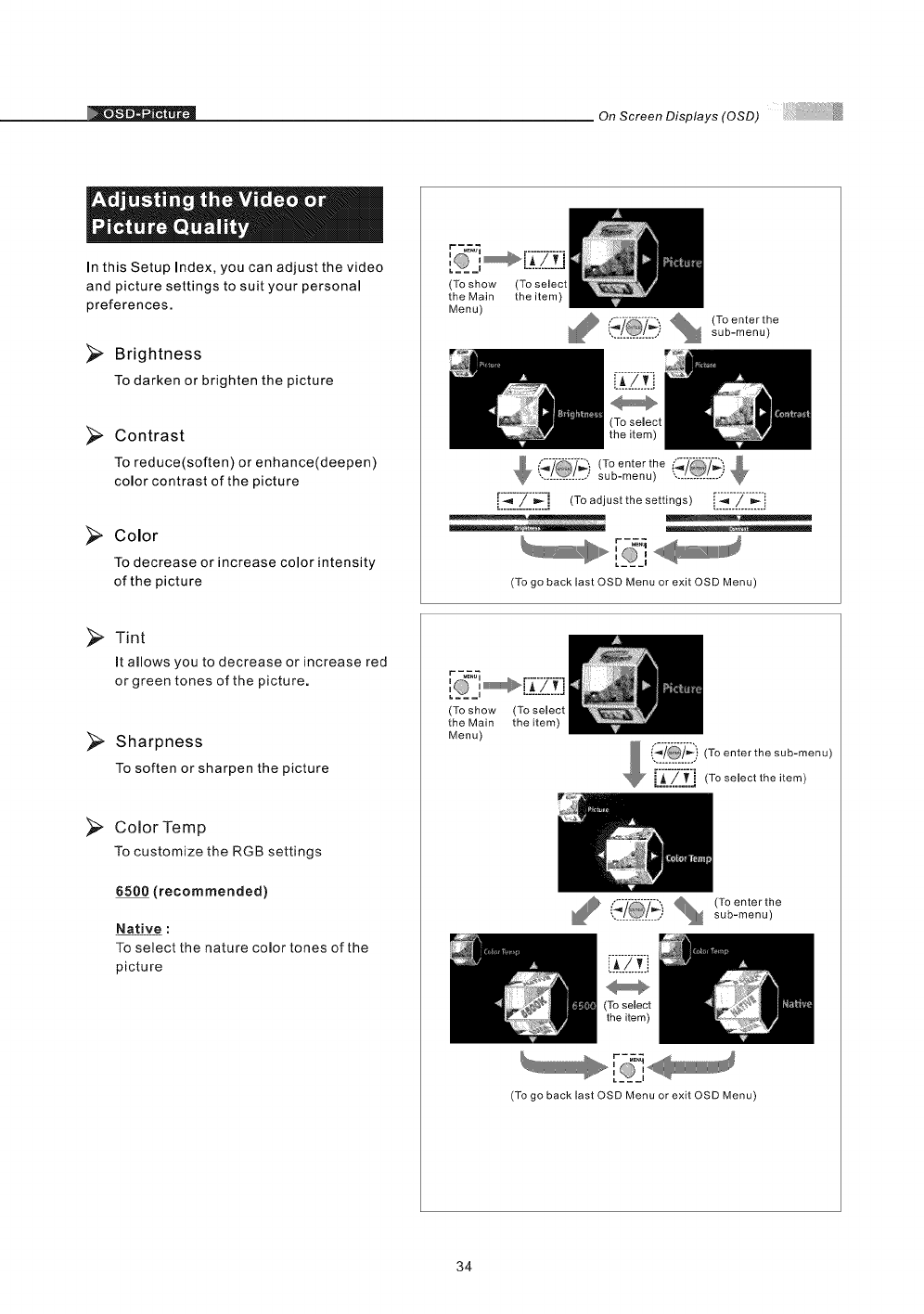
In this Setup Index, you can adjust the video
and picture settings to suit your personal
preferences.
Brightness
To darken or brighten the picture
Contrast
To reduce(soften) or enhance(deepen)
color contrast of the picture
Color
To decrease or increase color intensity
of the picture
(To show
the Main
Menu)
(To select
the item)
, @o/%!_7"_"[_.) (Toenterthe.... sub-menu)
(To enter the /_')
............... sub-menu) ...............
[I._.'.'IZII_] (To adjust the settings)[[_[[Z[[_'[!
:,'___'
(To go back last OSD Menu or exit OSD Menu)
Tint
It allows you to decrease or increase red
or green tones of the picture.
Sharpness
To soften or sharpen the picture
_, Color Temp
To customize the RGB settings
6500 (recommended)
Native :
To select the nature color tones of the
picture
(To show
the Main
Menu)
(To select
the item)
_1_' '.. I01 .., _ sub-menu)
f'_'"'-'_-_._, (To enter the
r-_
(To go back last OSD Menu or exit OSD Menu)
34
OnScreenDisplays(OSD)
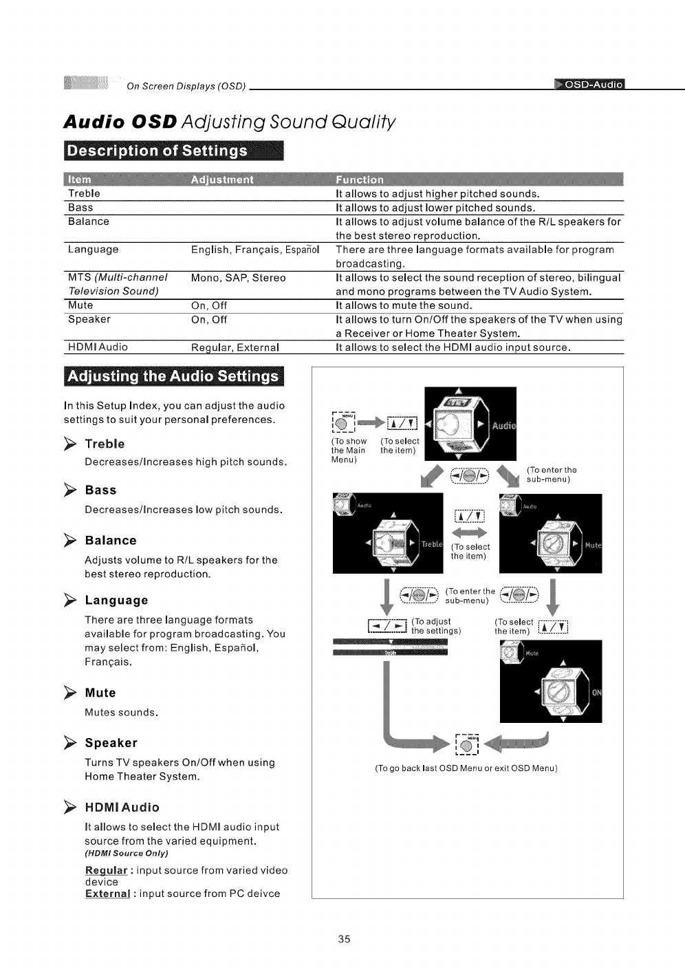
Audio OSD Adjusting Sound Quality
Treble It allows to adjust higher pitched sounds.
Bass It allows to adjust lower pitched sounds.
Balance It allows to adjust volume balance of the R/L speakers for
the best stereo reproduction.
Language Engmish, Fran_ais, Espa_ol There are three language formats available for program
broadcasting.
MTS (Multi-channel Mono, SAP, Stereo It allows to select the sound reception of stereo, bilingual
Television Sound) and mono programs between the TV Audio System.
Mute On, Off It allows to mute the sound.
Speaker On, Off It allows to turn On/Off the speakers of the TV when using
a Receiver or Home Theater System.
HDMI Audio Regular, External It allows to select the HDMI audio input source.
In this Setup Index, you can adjust the audio
settings to suit your personal preferences.
Treble
Decreases/Increases high pitch sounds.
Bass
Decreases/Increases low pitch sounds.
Balance
Adjusts volume to R/L speakers for the
best stereo reproduction.
Language
There are three language formats
available for program broadcasting. You
may select from: English, EspaRol,
Frangais.
Mute
Mutes sounds.
>
>
Speaker
Turns TV speakers On/Off when using
Home Theater System.
HDMIAudio
It allows to select the HDMI audio input
source from the varied equipment.
(HDMI Source Only)
: input source from varied video
device
External : input source from PC deivce
(To show (To select
the Main the item)
Menu)
Illl'£ i_7 % (To enter the............... sub-menu)
(To select
the item)
(_7 (To enter the
.............. sub-menu) .............
[[_[[Z[[_] (To adjust (To select
the settings) the item) [-A-7-_-i..............
r-_
[_,
(To go back mastOSD Menu or exit OSD Menu)
35
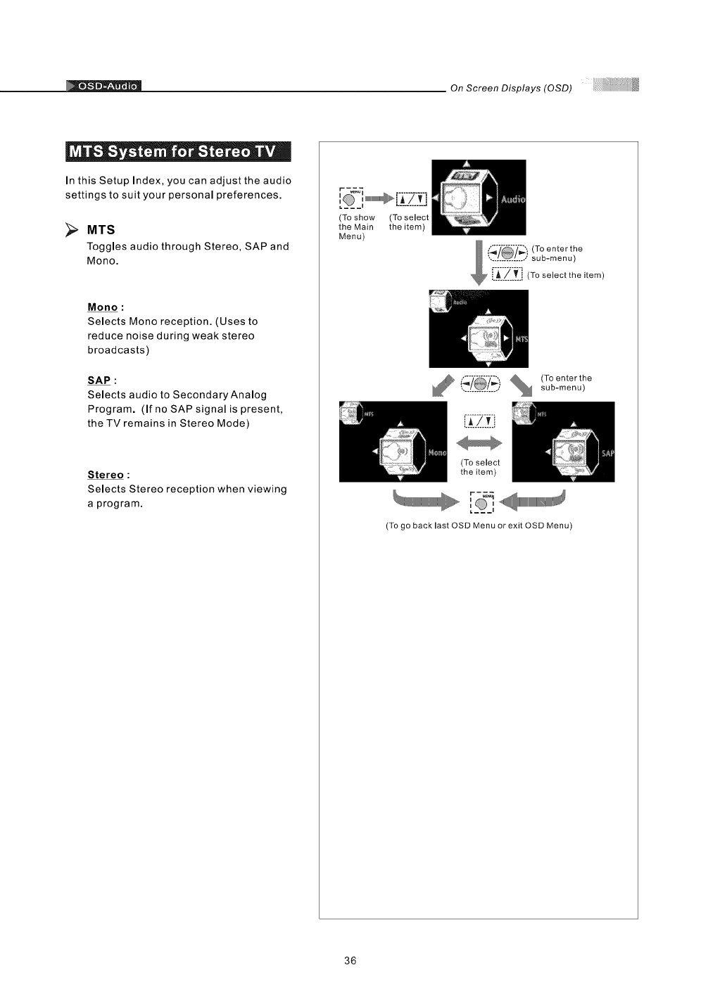
OnScreenDisplays(OSD)
= ® * _ Q
In this Setup Index, you can adjust the audio
settings to suit your personal preferences.
[]
MTS
Toggles audio through Stereo, SAP and
Mono.
Mono :
Selects Mono reception. (Uses to
reduce noise during weak stereo
broadcasts)
SAP :
Selects audio to Secondary Analog
Program. (If no SAP signal is present,
the TV remains in Stereo Mode)
Stereo :
Selects Stereo reception when viewing
a program.
(To show
the Main
Menu)
(To select
the item)
,% (Toenterthe
•.....'.' _ L....; sub-menu)
(To select
the item)
,0,1_=='<11_1111111111111111111111111111111111_
(To go back last OSD Menu or exit OSD Menu)
36
OnScreenDisplays(OSD)
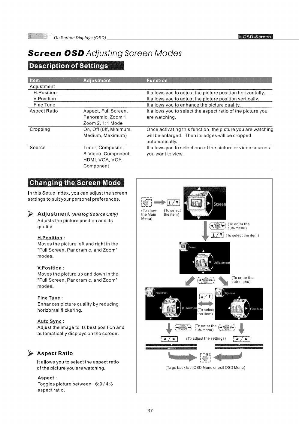
Screen OSD Adjusting Screen Modes
| ° e e • ° e_
Adjustment
H.Position It allows you to adjust the picture position horizontally.
V.Position It allows you to adjust the picture position vertically.
Fine Tune It allows you to enhance the picture quality.
Aspect Ratio Aspect, Full Screen, It allows you to select the aspect ratio of the picture you
Panoramic, Zoom I, are watching.
Zoom 2, 1:1 Mode
Cropping On, Off (Off, Minimum, Once activating this function, the picture you are watching
Medium, Maximum) will be enlarged. Then its edges will be cropped
automatically.
Source Tuner, Composite, It allows you to select one of the picture or video sources
S-Video, Component, you want to view.
HDMI, VGA, VGA-
Component
In this Setup Index, you can adjust the screen
settings to suit your personal preferences.
Adjustment (Analog Source Only)
Adjusts the picture position and its
quamity.
H.Position :
Moves the picture left and right in the
"Full Screen, Panoramic, and Zoom"
modes.
V.Position :
Moves the picture up and down in the
"Full Screen, Panoramic, and Zoom"
modes.
Fine Tune :
Enhances picture quality by reducing
horizontal flickering.
Auto Sync :
Adjust the image to its best position and
automatically displays on the screen.
>Aspect Ratio
It allows you to select the aspect ratio
of the picture you are watching.
Aspect :
Toggles picture between 16:9 /4:3
aspect ratio.
I m:,
(To show (To select
the Main the item)
Menu)
_ (To enterthe
,.............. sub-menu)
(T° enter the (_/
............... sub-menu) ...............
[I._"[[_Z_'"] (To adjust the settings)[i'_'::_'i:i_':i
r-_
I I
:,
(To go backlast OSD Menu or exit OSD Menu)
37
On Screen Displays (OSD)
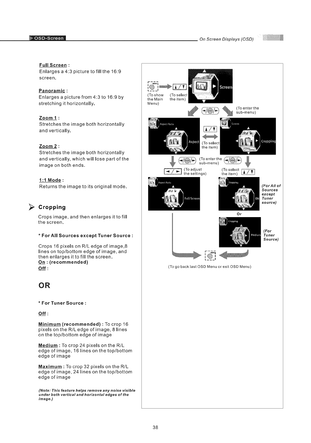
>
Full Screen :
Enlarges a 4:3 picture to fill the 16:9
screen.
Panoramic :
Enlarges a picture from 4:3 to 16:9 by
stretching it horizontally.
Zoom 1 :
Stretches the image both horizontally
and vertically.
Zoom 2 :
Stretches the image both horizontally
and vertically, which will lose part of the
image on both ends.
1:t Mode:
Returns the image to its original mode.
Cropping
Crops image, and then enlarges it to fill
the screen,
*For AI| Sources except Tuner Source :
Crops 16 pixels on R/L edge of image,8
lines on top/bottom edge of image, and
then enlarges it to fill the screen.
On : (recommended)
Off :
OR
*For Tuner Source :
Off :
Minimum (recommended) : To crop 16
pixels on the R/L edge of image, 8 lines
on the top/bottom edge of image
Medium : To crop 24 pixels on the R/L
edge of image, 16 lines on the top/bottom
edge of image
Maximum : To crop 32 pixels on the R/L
edge of image, 24 lines on the top/bottom
edge of image
(Note: This feature helps remove any noise visible
under both vertical and horizontal edges of the
image,)
(To show
the Main
Menu)
(To select
the item)
............... sub-menu)
(To enter the _'/_', &
............... sub-menu) ",..!._L..,,'
[°_"7"'_" i (To adjust (To select
' ' the settings) theitem) [:_:[_-_:_:.
Or
r-_._
[ _,
(To go backlast OSD Menu or exit OSD Menu)
(For AII of
Sources
except
Tuner
SOUrCe)
(For
Tuner
Source)
38
On Screen Displays (OSD)
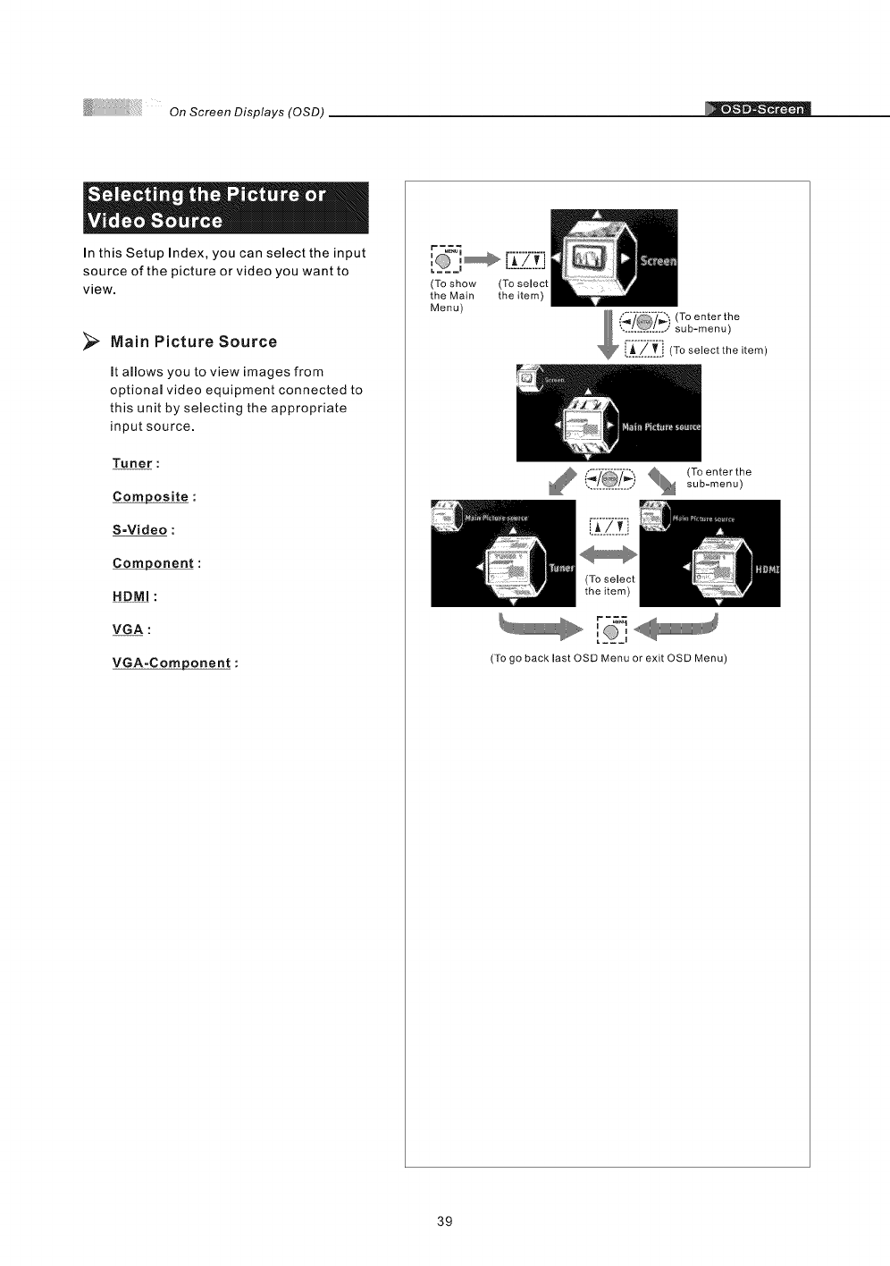
In this Setup Index, you can select the input
source of the picture or video you want to
view.
Main Picture Source
it allows you to view images from
optional video equipment connected to
this unit by selecting the appropriate
input source.
Tuner :
Composite :
S=Video :
Component :
HDMI :
VGA :
VGA=Component :
r_
ia
(To show (To select
the Main the item)
Menu)
f_-"_-':-l_',' _ (Toenterthe
,I@1... sub-menu)
(To go back last OSD Menu or exit OSD Menu)
39
+_ On Screen Displays (OSD)
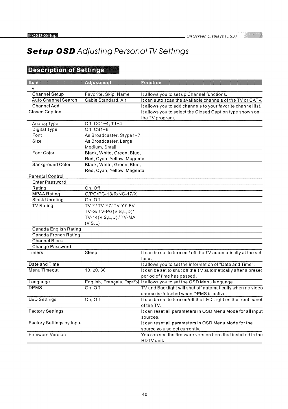
Setup OSD Adjusting Personal TV Settings
|+- ! e| • " |e
TV
Favorite, Skip, Name
Cable Standard, Air
Channel Setup
Auto Channel Search
ChannelAdd
Closed Caption
Analog Type
Digital Type
Font
Size
Font Color
Background Color
Parental Control
Enter Password
It allows you to set up Channel functions.
It can auto scan the available channels of the TV or CATV.
It allows you to add channels to your favorite channel list.
It allows you to select the Closed Caption type shown on
the TV program.
Off, CC1-4, T1-4
Off, CS1-6
As Broadcaster, Stypel-7
As Broadcaster, Large,
Medium, Small
Black, White, Green, Blue,
Red, Cyan, Yellow, Magenta
Black, White, Green, Blue,
Red, Cyan, Yellow, Magenta
Rating On, Off
MPAA Rating G/PG/PG-13/R/NC-17IX
Block Unrating On, Off
TV Rating TV-Y/TV-Y7/TV-Y7-FV
TV-G/TV-PG(V,S,L,D)/
TV-14(V,S, L, D) /TV-MA
(V,S,L)
Canada English Rating
Canada French Rating
Channel Block
Change Password
Timers Sleep It can be set to turn on /off the TV automatically at the set
time.
Date and Time It allows you to set the information of "Date and Time".
Menu Timeout 10, 20, 30 It can be set to shut off the TV automatically after a preset
period of time has passed.
Language English, Fran_ais, Espafiol It allows you to set the OSD Menu language.
DPMS On, Off TV and Backlight will shut off automatically when no video
source is detected when DPMS is active.
LED Settings On, Off It can be set to turn on/off the LED Light on the front panel
of the TV.
Factory Settings It can reset all parameters in OSD Menu Mode for all input
sources.
Factory Settings by Input It can reset all parameters in OSD Menu Mode for the
source you select currently.
Firmware Version You can see the firmware version here that installed in the
HDTV unit.
4O
OnScreenDisplays(OSD)
][" . | fto fl " | . I | "
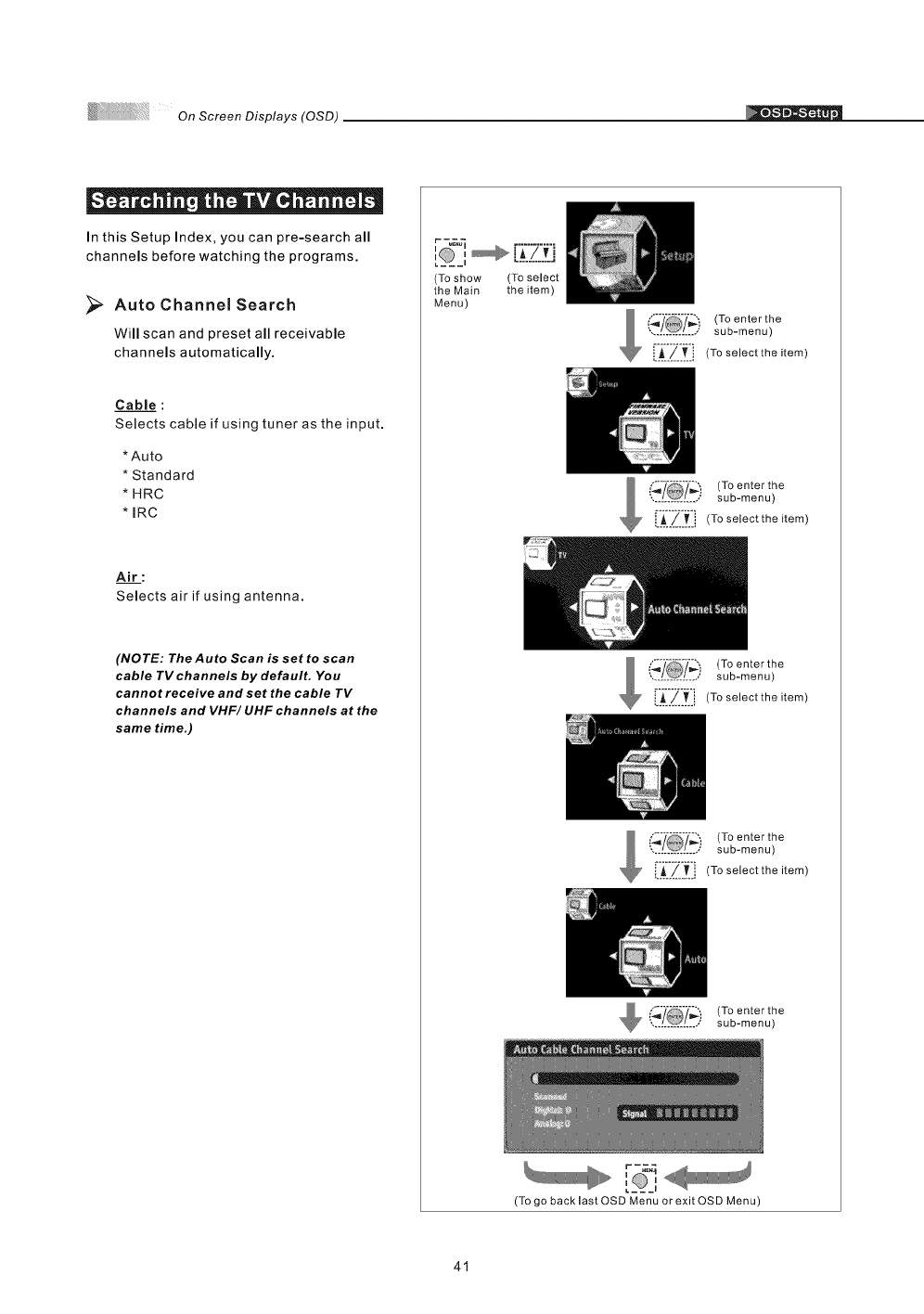
In this Setup Index, you can pre-search all
channels before watching the programs.
Auto Channel Search
Will scan and preset all receivable
channels automatically.
Cable :
Selects cable if using tuner as the input.
*Auto
* Standard
* HRC
* IRC
Air :
Selects air if using antenna.
(NOTE: The Auto Scan is set to scan
cable TV channels by default, You
cannot receive and set the cable TV
channels and VHF/ UHF channels at the
same time.)
r -_
:, ,B.:Z:fl
(To show (To select
the Main the item)
Menu)
J_!_} (To enter the
............... sub-menu)
[A_.-/-___-_i(To select the item
_j (To enter the
............... sub-menu)
i_/[j (To selectthe item
{-,4 _ sub-menu)
', /_/ .,' (Toenterthe
!._.._..[.i (Toselecttheitem
i_'/ (To enter the
*,............... sub-menu)
[A !__j (To selectthe item
_i_/ (To enterthe
*,............... sub-menu)
41
[__,
(To go back last OSD Menu or exit OSD Menu)
On Screen Displays (OSD)
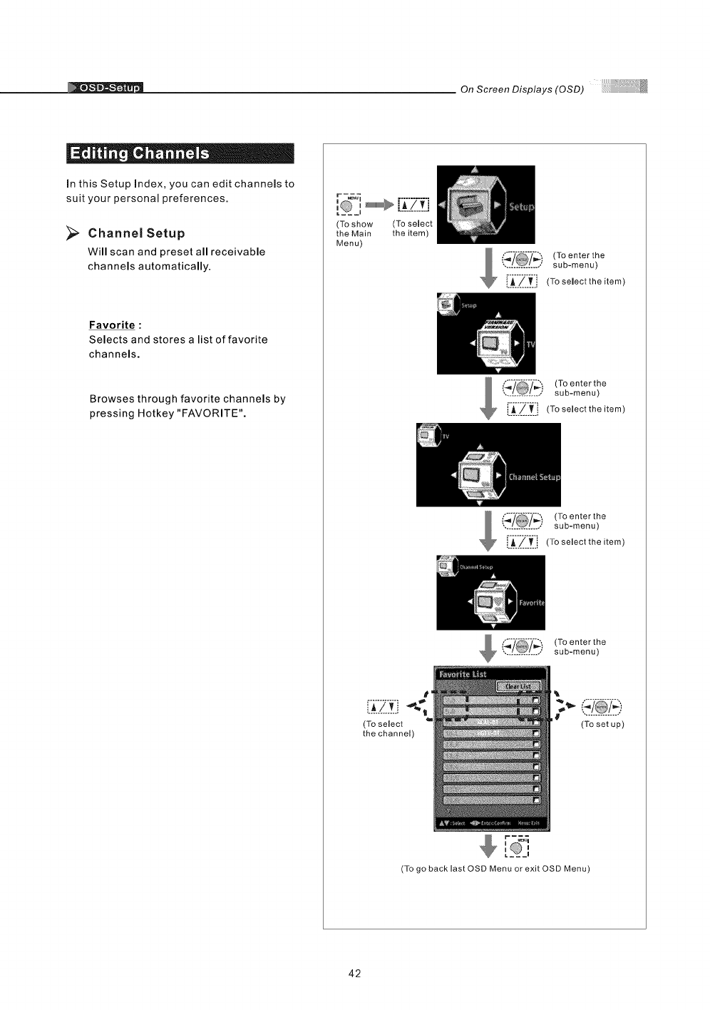
In this Setup Index, you can edit channels to
suit your personal preferences.
Channel Setup
Will scan and preset all receivable
channels automatically.
[]
Favorite :
Selects and stores a list of favorite
channels.
Browses through favorite channels by
pressing Hotkey "FAVORITE".
,'__'_,+_ [f7 +i
,,............
(To show (To select
the Main the item)
Menu)
(To enter the
............... sub-menu)
i_A__/_[_' (To select the item)
+ :,:)(To enter the
............... sub-menu)
LA.../.._.i (To select the item)
(_'/ (To enter the
.............. sub-menu)
[IA_I'_::_II (To selectthe item)
_(_ (To enterthe
............... sub-menu)
L__!_.[_i
(To select
the channel)
+++©,
a__J
(To set up)
(To go back last QSD Menu or exit OSD Menu)
42
OnScreenDisplays(OSD)
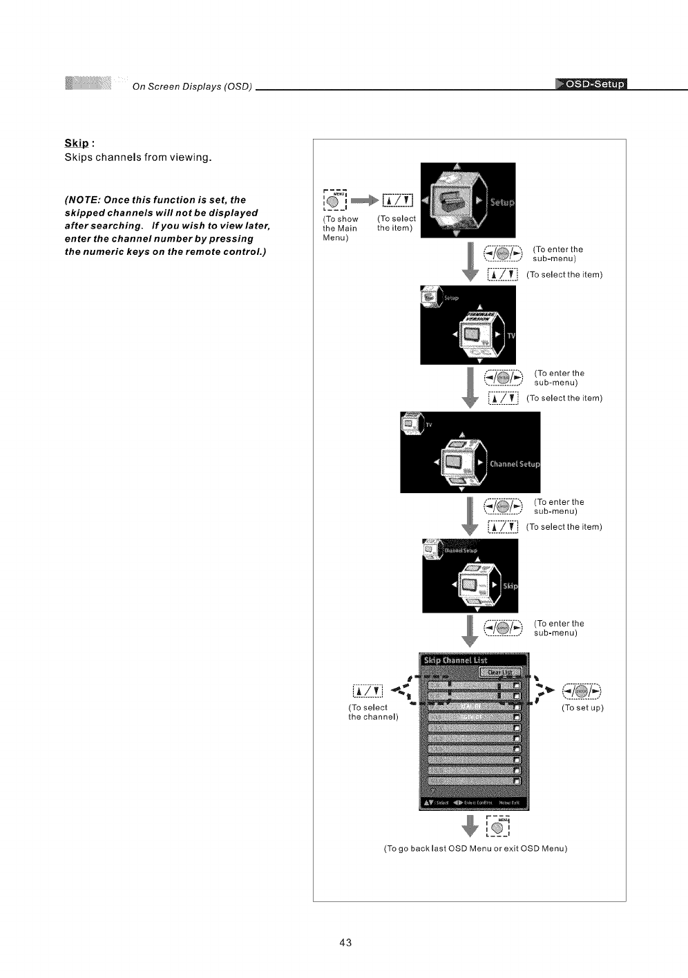
Skips channels from viewing.
(NOTE: Once this function is set, the
skipped channels will not be displayed
after searching. If you wish to view later,
enter the channel number by pressing
the numeric keys on the remote control.)
(To show (To select
the Main the item)
Menu)
_. _/ ," (Toenterthe
sub-menu)
_:_ii_'_:i (To select the item)
,, /_I / (Toenterthe
sub-menu)
[A_/_[_, (To selectthe item)
_ {'._'/ i (To enter the
-............... - sub-menu)
[:_i'_'_.: i (To select the item)
(,'_ (To enter the
............... sub-menu)
L_.!!.,
(To select
the channel)
r-_
(To set up)
(To go back last OSD Menu or exit OSD Menu)
43
._ On Screen Displays (OSD)
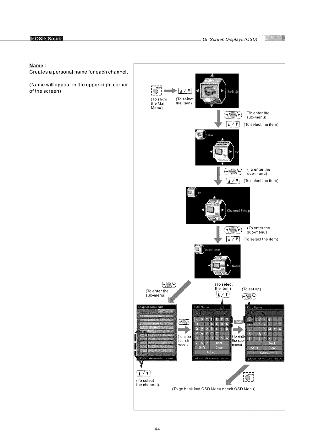
Name :
Creates a personal name for each channel.
(Name will appear in the upper-right corner
of the screen)
(To show
the Main
Menu)
[]
A/vi
(To select
the channel)
(To select
the item)
(To enter the
sub-menu)
[-A--/-_-i (To seleotthe item)
_ "_--'_-_-_ sub-menu)
',. /0/.; (Toenterthe
_.../..._ i (To select the item)
(To enter the
sub-menu)
[-_-._._-_._i (To select the item)
(To select
the item) (To set up)
i__./____i_:_
(To go back last OSD Menu or exit OSD Menu)
44
OnScreenDisplays(OSD)
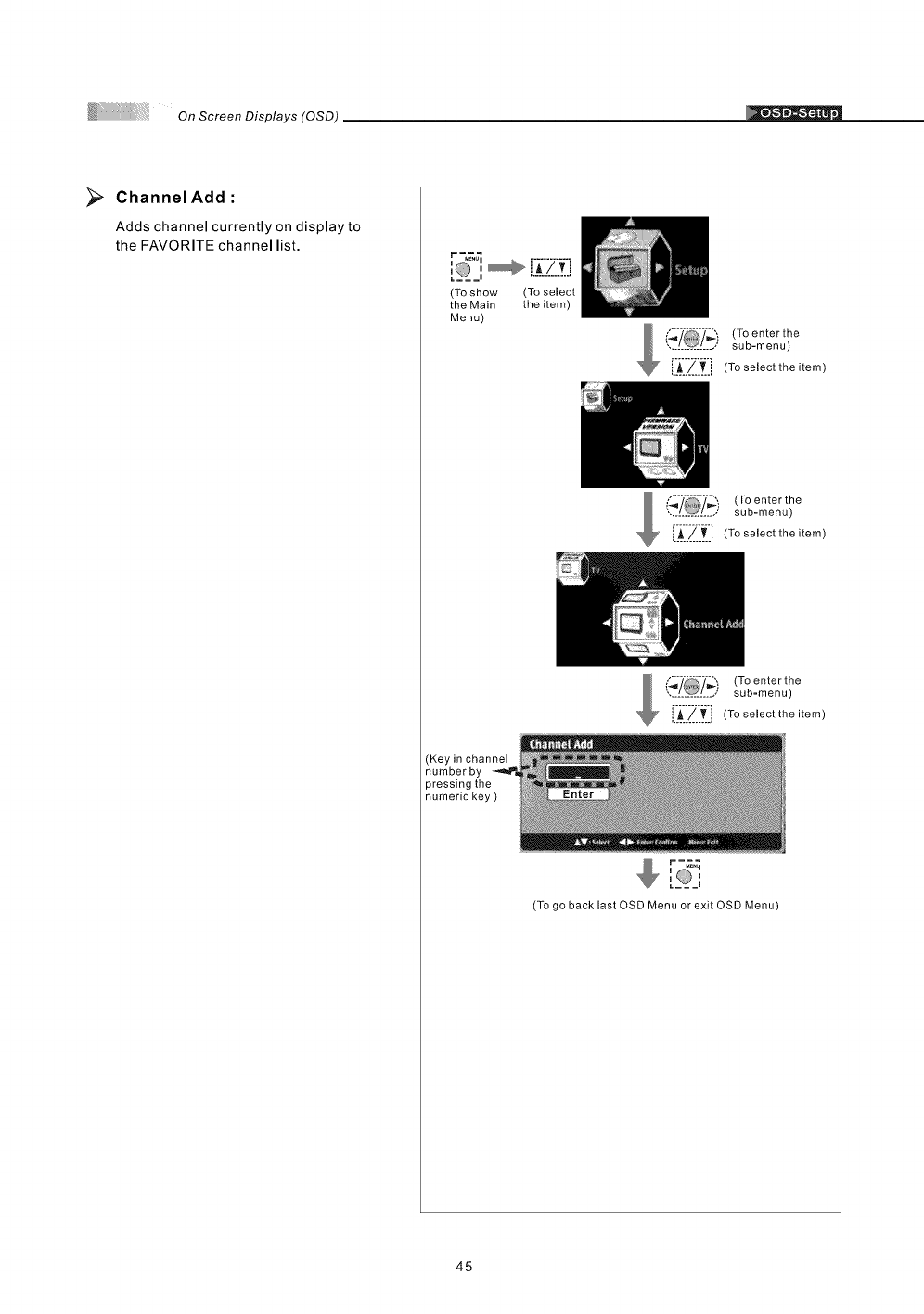
_;_ Channel Add
Adds channel currently on display to
the FAVORITE channel list.
I m
(To show (To select
the Main the item)
Menu)
(To enterthe
............... sub-menu)
r_"7_T'i (To selectthe item
(To enter the
sub-menu)
___=_z._:__[-A--7-T"(To selectthe item
(Keyin channel
numberby
pressingthe
numerickey)
{,'_7 (To enter the
............... sub=menu)
i_/Ti (To select the item
i i
r-_q
[ _,
(To go back last OSD Menu or exit OSD Menu)
45
On Screen Displays (OSD)
O _ Q _ Q • 0 O •
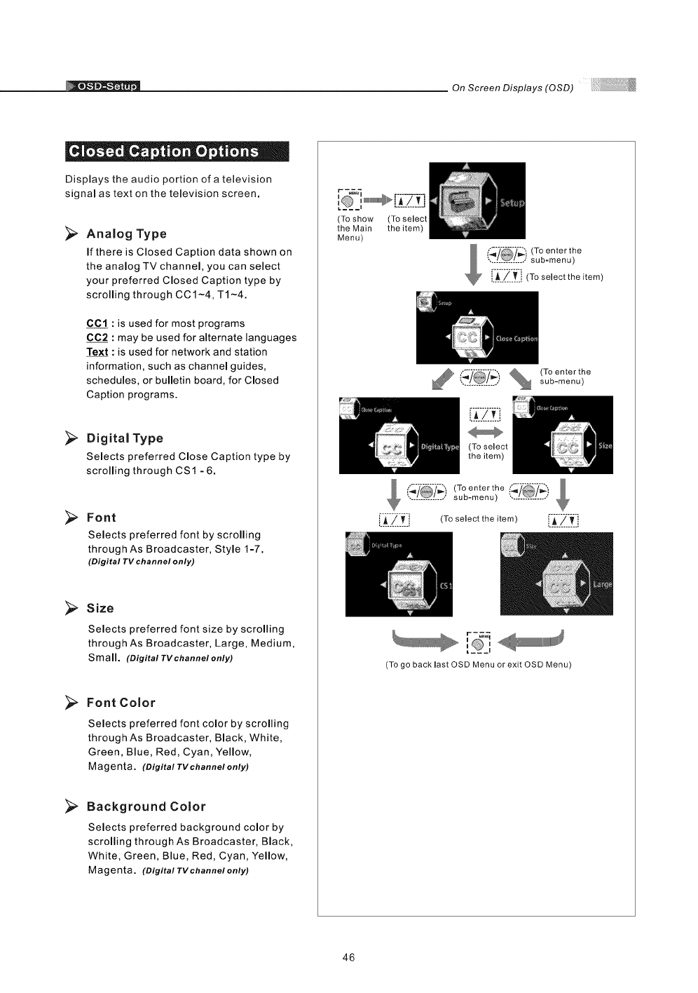
Displays the audio portion of a television
signal as text on the television screen.
>Analog Type
If there is Closed Caption data shown on
the analog TV channel, you can select
your preferred Closed Caption type by
scrolling through CC1-4, T1-4.
CC1 : is used for most programs
CC2 :may be used for alternate languages
Text : is used for network and station
information, such as channel guides,
schedules, or bulletin board, for Closed
Caption programs.
Digital Type
Selects preferred Close Caption type by
scrolling through CS1 - 6.
>Font
Selects preferred font by scrolling
through As Broadcaster, Style I-7.
(Digital TVchannel only)
Size
Selects preferred font size by scrolling
through As Broadcaster, Large, Medium,
Small. (Digital TV channel only)
Font Color
Selects preferred font color by scrolling
through As Broadcaster, Black, White,
Green, Blue, Red, Cyan, Yellow,
Magenta. (Digital TV channe/ only)
>Background Color
Selects preferred background color by
scrolling through As Broadcaster, Black,
White, Green, Blue, Red, Cyan, Yellow,
Magenta. (Digital TV ehannel only)
(To show
the Main
Menu)
(To select
the item)
,_ i_7 (To enterthe
............... sub-menu)
A/[.i (To select the item)
_, ('_'_ %(To enter the
............... sub-menu)
i',_7 (To enter the
...... ______,sub-menu) ...............
[1_1/_-.__:', (To select the item) iii:'Z:__:i
,'___'
(To go back last OSD Menu or exit OSD Menu)
46
On Screen Displays (OSD) [
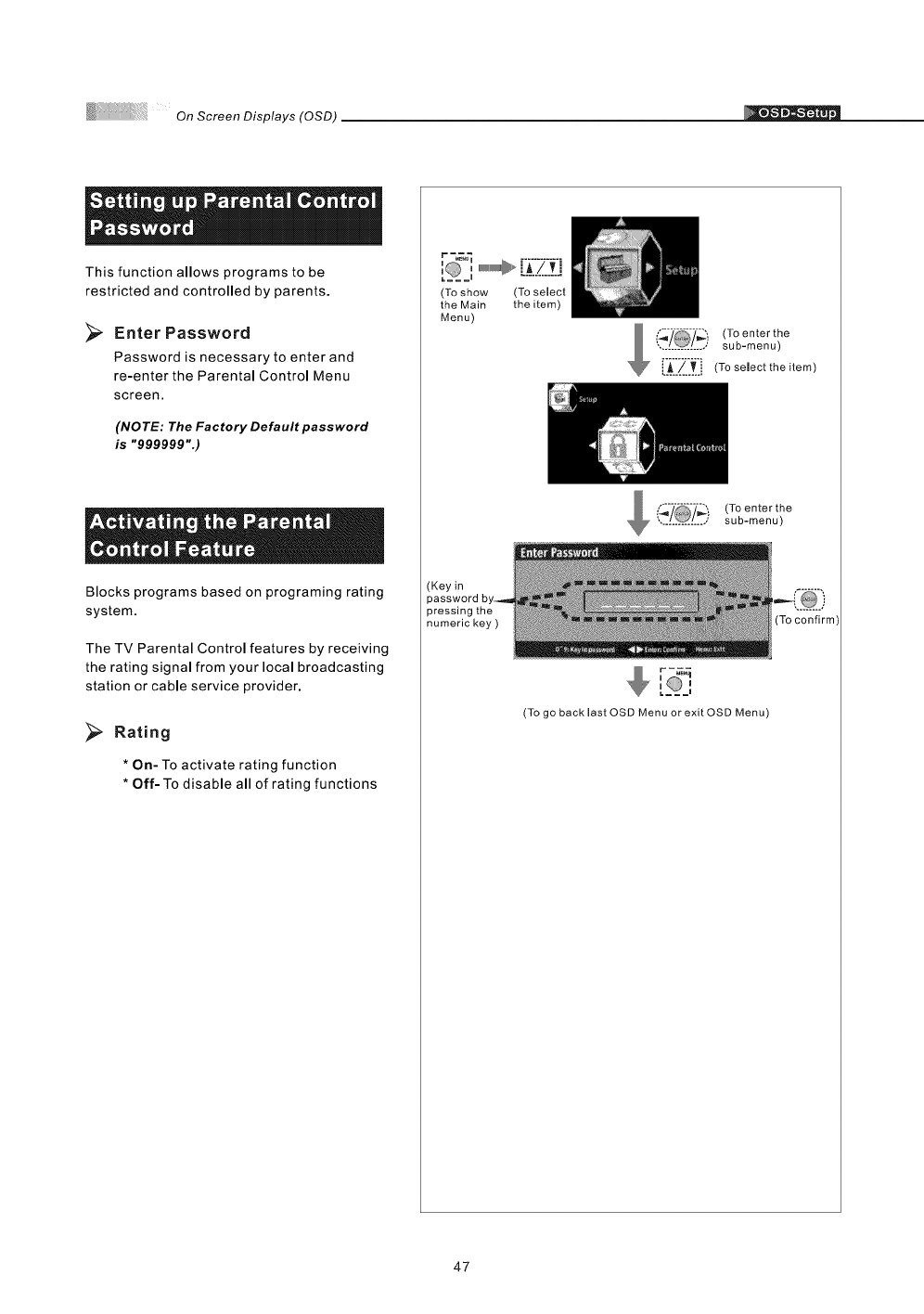
This function allows programs to be
restricted and controlled by parents.
>Enter Password
Password is necessary to enter and
re-enter the Parental Control Menu
screen.
(NOTE: The Factory Default password
is "999999".)
Blocks programs based on programing rating
system.
The TV Parental Control features by receiving
the rating signal from your local broadcasting
station or cable service provider.
_;_ Rating
* On- To activate rating function
* Off- To disable all of rating functions
r-_7_
,'= = =,, ,,,,UlUlUlUlUlUlU_P,. .['i"7"_'i...........
(To show (To select
the Main the item)
Menu)
,,"_;----Z',,
', /O/ ; (Toenterthe
sub-menu)
i,_/..._.[ (To select the item)
_ _'_ (To enter the............... sub-menu)
(Key in
pressing the
numeric key )
I I
r-_
(To go back last OSD Menu or exit OSD Menu)
47
On Screen Displays (OSD)
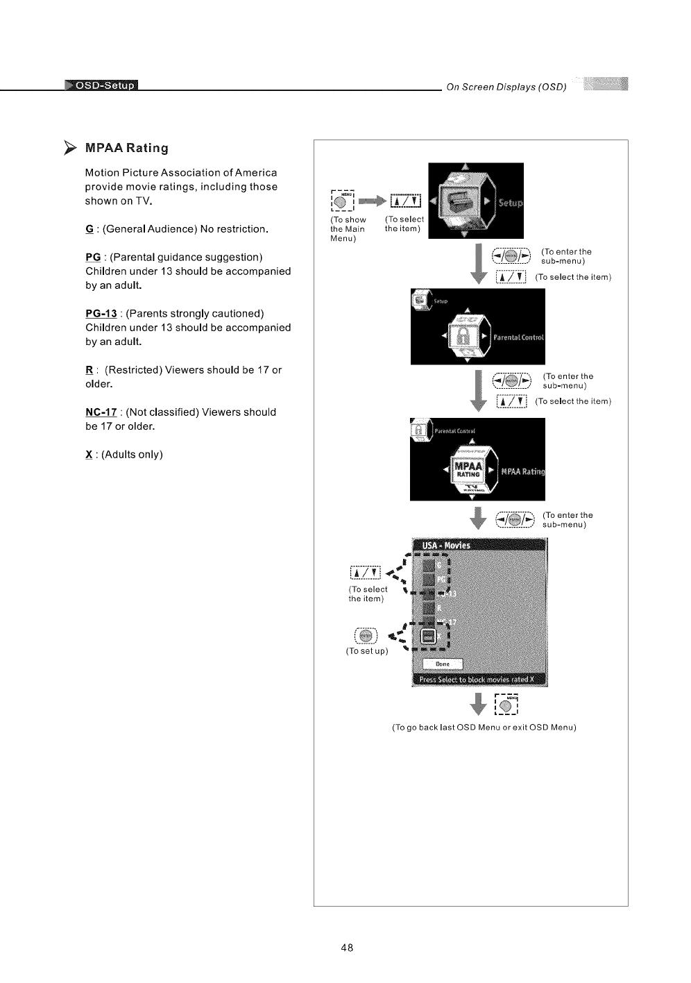
>MPAA Rating
Motion Picture Association of America
provide movie ratings, including those
shown on TV.
G=: (General Audience) No restriction.
P G : (Parental guidance suggestion)
Children under 13 should be accompanied
by an adult.
PG-13 : (Parents strongly cautioned)
Children under 13 should be accompanied
by an adult.
=R: (Restricted) Viewers should be 17 or
older.
NC-17 : (Not classified) Viewers should
be 17 or older.
X : (Adults only)
r -_
I__il
(To show (To select
the Main the item)
Menu)
l(_.__i! (To enter the
sub=menu)
[i iZi i! Toso,oettho,tom
(To enter the
............... sub=menu)
LL/..[i (Toseleettheitem)
(_ (To enter the
............... sub-menu)
(To select
the item)
<.
(To set up)
ai
[_@_=,
(To go back last OSD Menu or exit OSD Menu)
48
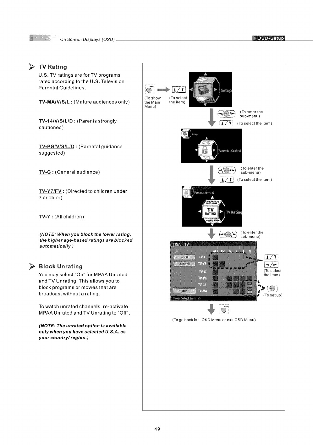
>. TV Rating
U.S. TV ratings are for TV programs
rated according to the U.S. Television
Parental Guidelines.
TV-MAIVlSIL : (Mature audiences only)
TV=141VlSILID : (Parents strongly
cautioned)
TV=PGIVlSILID :(Parental guidance
suggested)
!Y_Q : (General audience)
TV=Y7/FV : (Directed to children under
7 or older)
TV-Y :(Allchildren)
(NOTE: When you block the Iower rating,
the higher age-based ratings are blocked
automatically.)
Block Unrating
You may select "On" for MPAA Unrated
and TV Unrating. This allows you to
block programs or movies that are
broadcast without arating.
To watch unrated channels, re-activate
MPAA Unrated and TV Unrating to "Off".
(NOTE: The unrated option is available
only when you have selected U.S.A. as
your coun try/region.)
r -_
'L'___',@w_ _[i7_i...........
Ta shaw (To select
the Main the item)
Menu)
(_'/ (Ta enter the
............... sub-menu)
R [_./.____i (Ta select the item
(Ta enter the
..[[[[[[[[o, SUb- m en u )
L_../_. i (Ta select the item
(_7 (Ta enter the
............... sub-menu)
I I
r-_
[ =,
(To go back last OSD Menu ar exit OSD Menu)
(To select
the item)
t@)
(To set up)
49
On Screen Displays (OSD)
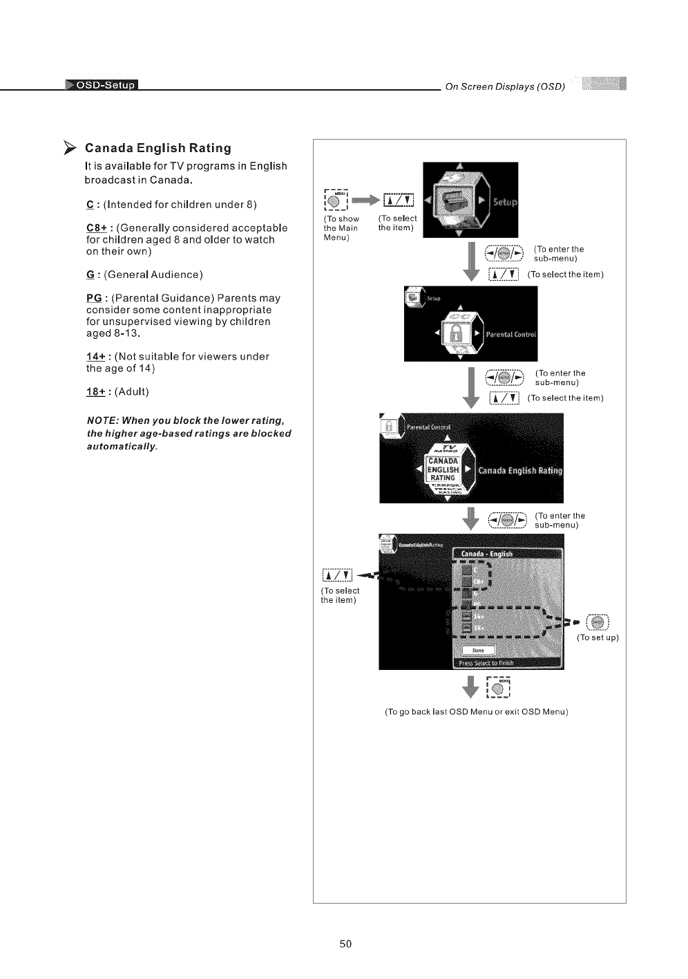
>Canada English Rating
It is available for TV programs in English
broadcast in Canada.
C : (Intended for children under 8)
C8+ : (Generally considered acceptable
for children aged 8 and older to watch
on their own)
G:(General Audience)
P G : (Parental Guidance) Parents may
consider some content inappropriate
for unsupervised viewing by children
aged 8=13.
14+ : (Not suitable for viewers under
the age of 14)
18+ : (Adult)
NOTE: When you block the lower rating,
the higher age-based ratings are blocked
automatically.
(To show
the Main
Menu)
(To select
the item)
(To select
the item)
(To enterthe
............... • sub-menu)
!__Z.__i (To selectthe item)
mi !_ _ (Toenterthe
,,,_..._,.._,, su b- me nu )
i_/T i (To select the item)
(To enterthe
............... sub-menu)
r-_
(To setup)
(To go back last OSD Menu or exit OSD Menu)
50
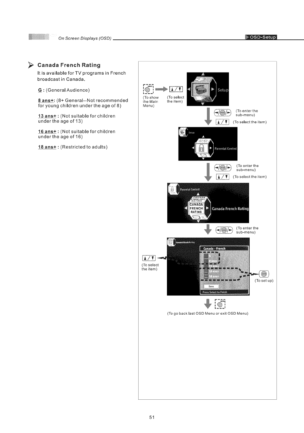
Canada French Rating
It is available forTY programs in French
broadcast in Canada.
G : (Generam Audience)
8ans+: (8+ General--Not recommended
for young children under the age of 8)
: (Not suitabme for children
under the age of 13)
16 arts+ : (Not suitabme for children
under the age of 16)
18 ans+: (Restricted to adults)
, [:(:?.::f:i
(To show (To select
the Main the item)
Menu)
(To select
the item)
(To enter the
............... sub-menu)
i.A/,T.i (To select the item)
(To enterthe
sub-menu)
[i_-Zi_i (To select the item)
To enterthe
sub-menu)
ai
_ =;,.q
[O,
(To go back last OSD Menu or exit OSD Menu)
(To set up)
51
On Screen Displays (OSD)
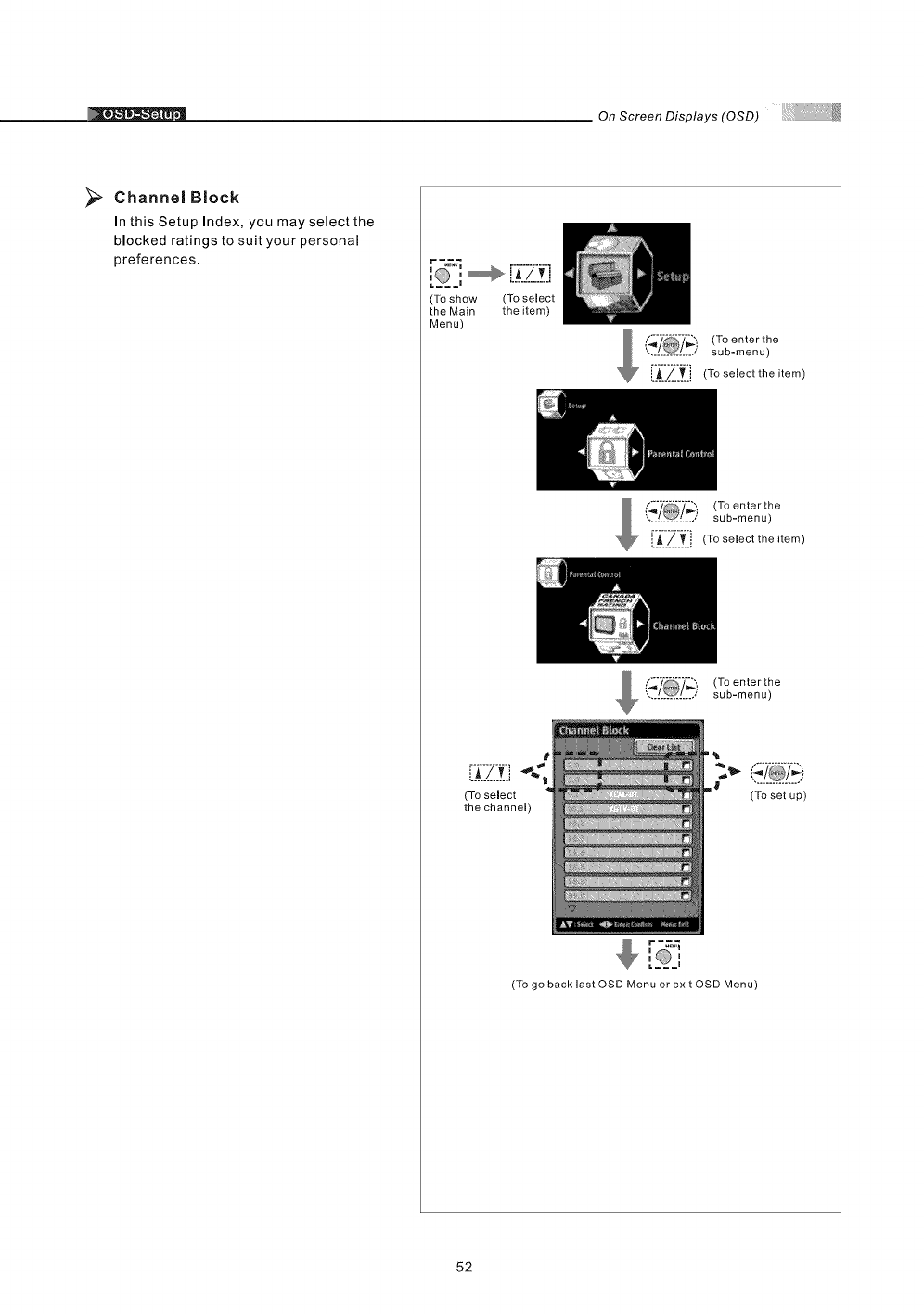
>Channel Block
In this Setup Index, you may select the
blocked ratings to suit your personal
preferences.
I m
:, [i Zf-!
(To show (To select
the Main the item)
Menu)
_ _7_i (To enter the
............... sub-menu)
i._../_..i (To select the item)
,/@/, (Toenterthe
sub-menu)
/_j (To select the item)
m == I
r=_
(To enterthe
sub-menu)
(To select
the channel)
(To set up)
(To go back last OSD Menu or exit OSD Menu)
52
On Screen Displays (OSD) I
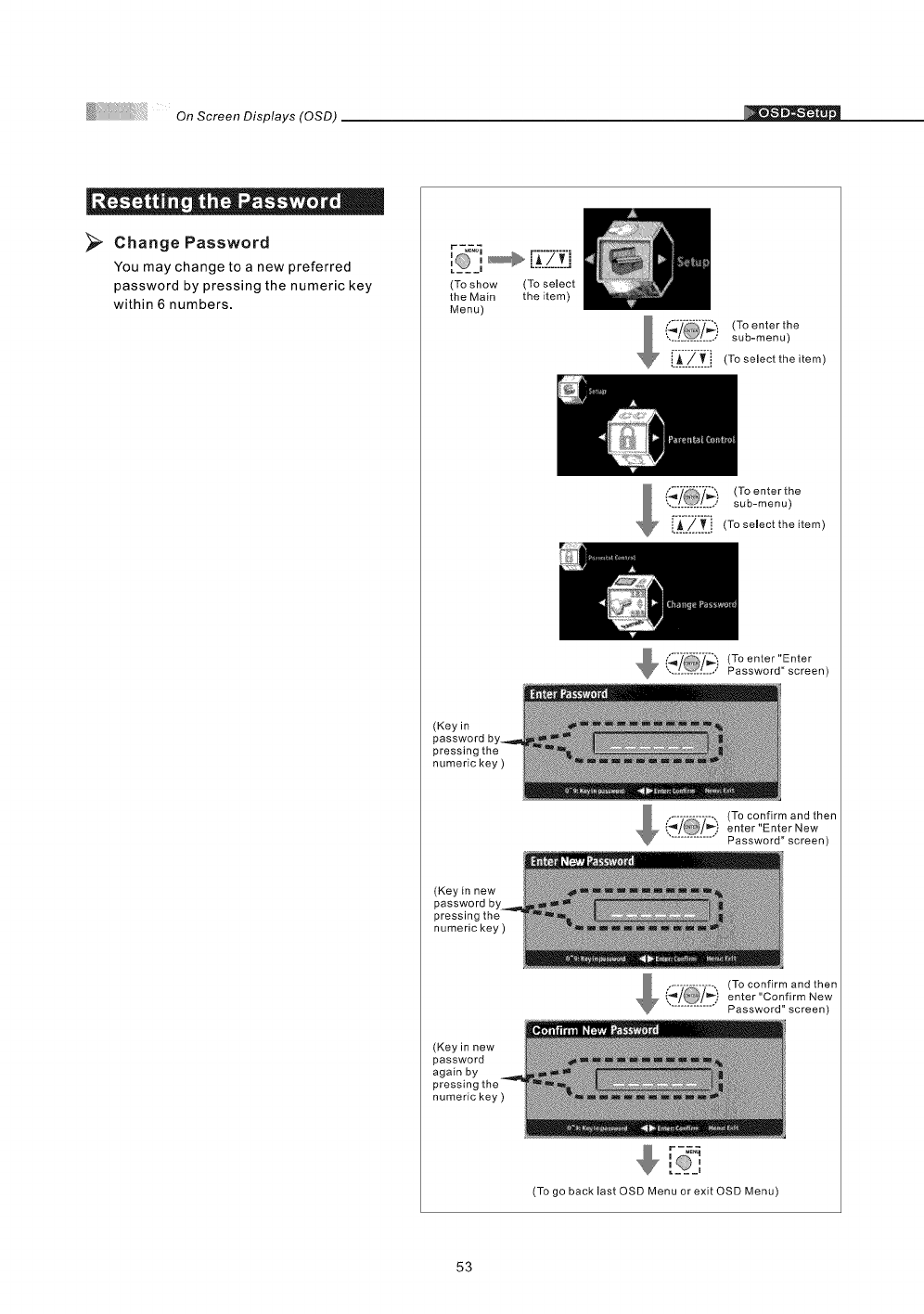
>Change Password
You may change to a new preferred
password by pressing the numeric key
within 6 numbers.
r -_
:,
(To show (To select
the Main the item)
Menu)
('._ (To enter the
.............. sub-menu)
['_'.'-/-]]_-]i (To select the item)
(To enterthe
............... sub-menu)
i._._._.i (To select the item)
_[_- Password" screen)
',. _/ ,,' (Toenter"Enter
(Key in
password
pressing the
numeric key )
(To confirm and then
enter"Enter New
............... Password" screen)
(Key in new
pressing the
numeric key )
(Key in new
password
again by
numeric key )
(To confirm and then
enter "Confirm New
............... Password" screen)
(To go back last OSD Menu or exit OSD Menu)
53
On Screen Displays (OSD)
" O " ii .%e "
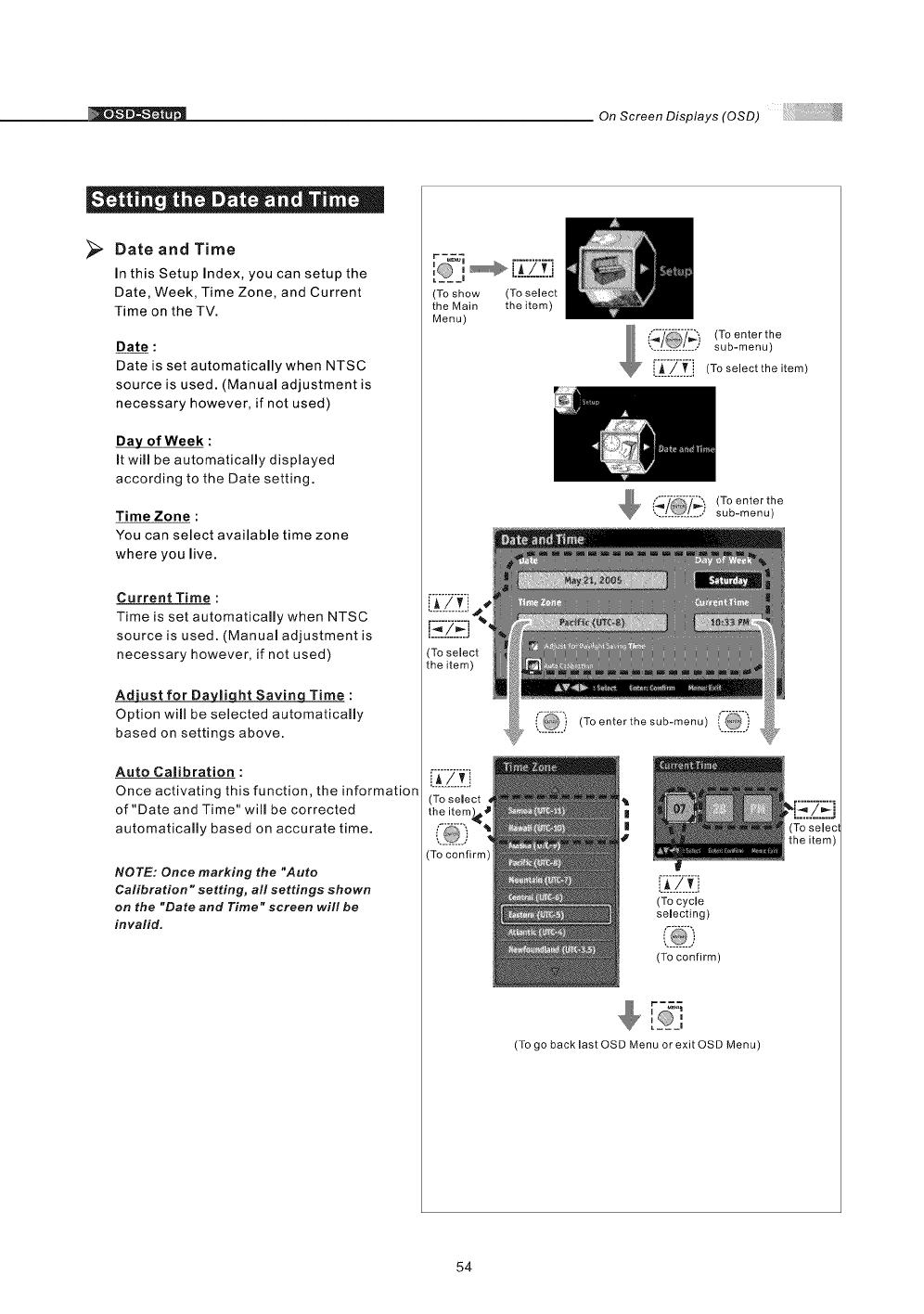
>Date and Time
In this Setup Index, you can setup the
Date, Week, Time Zone, and Current
Time on the TV.
Date :
Date is set automatically when NTSC
source is used. (Manual adjustment is
necessary however, if not used)
Day of Week :
It will be automatically displayed
according to the Date setting.
Time Zone :
You can select available time zone
where you live.
Current Time :
Time is set automatically when NTSC
source is used. (Manuam adjustment is
necessary however, if not used)
Adjust for Da_liqht Savinq Time :
Option will be selected automatically
based on settings above.
Auto Calibration :
Once activating this function, the information
of "Date and Time" will be corrected
automatically based on accurate time.
NOTE: Once marking the "Auto
Calibration °'setting, all settings shown
on the "Date and Time" screen will be
invalid.
r _._
I___ I
(To show (To select
the Main the item)
Menu)
)(To enter the
•.[[[[[[[[[[[[[** sub-menu)
i_$_/_., (To selectthe item)
(To enter the
............... sub-menu)
(i_[[) (To enter the sub-menu
L__!.L
(To cycle
selecting)
(To confirm)
[_O_,
(To go back last OSD Menu or exit OSD Menu)
54
On Screen Displays (OSD)
"o| " || "
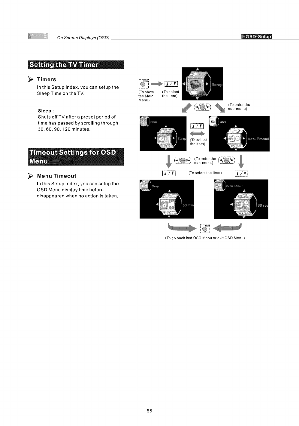
Timers
In this Setup Index, you can setup the
Sleep Time on the TV.
Sleep :
Shuts offTV after a preset period of
time has passed by scrolling through
30, 60, 90,120 minutes.
Menu Timeout
In this Setup Index, you can setup the
OSD Menu display time before
disappeared when no action is taken.
(To show
the Main
Menu)
(To select
the item)
,./@/,, sob-menu)
i_/ (To enter the
............... sub-menu) ...............
[i_:'/_'_:i (To seJect the item) [_:]_._'._:i
'_D ,lJ
_@,
(To go backiast OSD Menu or exit OSD Menu)
55
OnScreenDisplays(OSD)
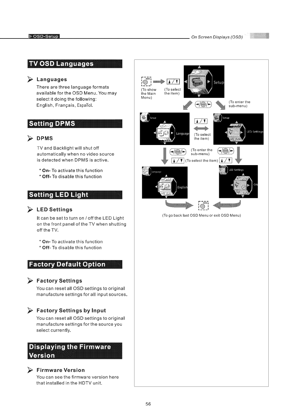
Languages
There are three language formats
available for the OSD Menu. You may
select it doing the following:
English, Frangais, Espa_ol.
DPMS
TV and Backlight will shut off
automatically when no video source
is detected when DPMS is active,
*On- To activate this function
*Off- To disable this function
= = I _ i|
>LED Settings
It can be set to turn on /off the LED Light
on the front panel of the TVwhen shutting
off the TV.
* On- To activate this function
* Off- To disable this function
.i III _ . IIo ®
Factory Settings
You can reset all OSD settings to original
manufacture settings for all input sources,
>Factory Settings by Input
You can reset all OSD settings to original
manufacture settings for the source you
select currently.
Firmware Version
You can see the firmware version here
that installed in the HDTV unit.
r -_
i i
(To show (To select
the Main the item)
Menu)
% (To enter the
,.............. sub-menu)
iA/vi
(To select
the item)
_, r-_&_
[__,
(To go back last OSD Menu or exit OSD Menu)
56
ifications
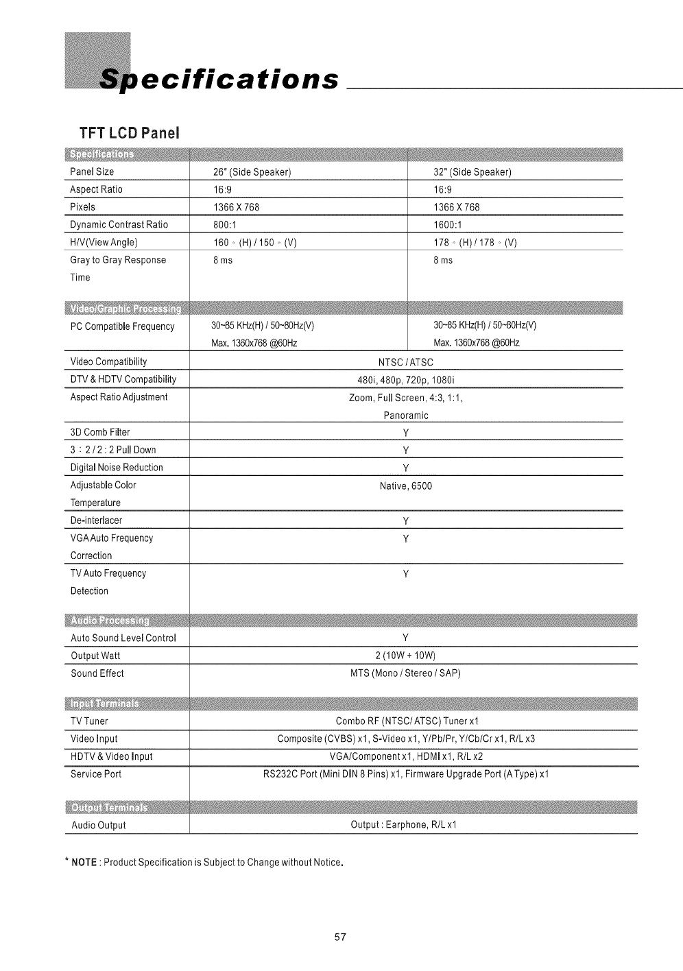
TFT LCD Panel
Panel Size
Aspect Ratio
Pixels
Dynamic Contrast Ratio
H/V(ViewAngle)
Gray to Gray Response
Time
PC Compatible Frequency
26" (Side Speaker)
16:9
1366X768
800:1
160,, (H)/150 o (V)
8ms
30~85KHz(H)/50~80Hz(V)
Max.1360x768@60Hz
Video Compatibility
DTV & HDTV Compatibility
Aspect Ratio Adjustment
3D Comb Filter
3 : 2/2:2 Pull Down
Digital Noise Reduction
Adjustable Color
Temperature
De-interlacer Y
VGAAuto Frequency y
Correction
YTV Auto Frequency
Detection
32" (Side Speaker)
16:9
1366X768
1600:1
178o (H)/178 o (V)
8ms
30~85KHz(H)/50~8OHz(V)
Max.I360x768@6OHz
NTSC/ATSC
480i, 480p, 720p, 1080i
Zoom, FullScreen,4:3, 1:1,
Panoramic
Y
Y
Y
Native, 6500
Auto Sound Level Control Y
Output Watt 2 (10W + 10W)
Sound Effect MTS (Mono IStereo /SAP)
TV Tuner Combo RF (NTSC/ATSC) Tuner xl
Video Input Composite (CVBS) xl, S-Video xl, YIPblPr, YlCblCrxl, R/Lx3
HDTV & Video Input VGA/Component xl, HDMI xl, R/L x2
Service Port RS232C Port (Mini DIN 8 Pins) xl, Firmware Upgrade Port (AType) xl
Audio Output Output : Earphone, R/L xl
* NOTE : Product Specification is Subject to Change without Notice.
57
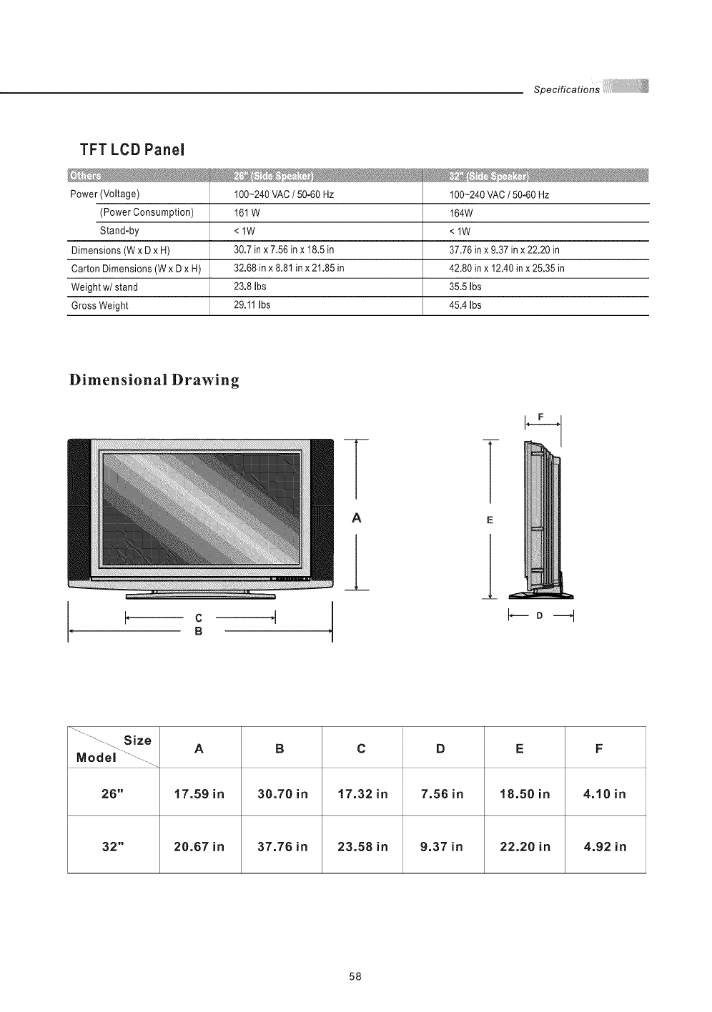
TFT LCD Panel
Power (Voltage)
(Power Consumption)
Stand-by
Dimensions (W x D x H)
Carton Dimensions (W x D x H)
Weight w/stand
Gross Weight
'
100-240 VAC /50-60 HZ
161 W
<lW
30.7 in x 7.56 in x 18.5 in
32.68 in x 8.81 in x 21.85 in
23.8 Ibs
29.11 Ibs
.... _ _ .........
100-240 VAC /50-60 Hz
164W
<lW
37.76 in x 9.37 in x 22.20 in
42.80 in x 12.40 in x 25.35 in
35.5 Ibs
45.4 Ibs
Dimensional Drawing
E
....._..... Size A B C D E F
Model ...........
26" 17.59 in 38.78 in 17.32 in 7.56 in 18.50 in 4.10 in
32" 20.67 in 37.76 in 23.58 in 9.37 in 22.20 in 4.92 in
58
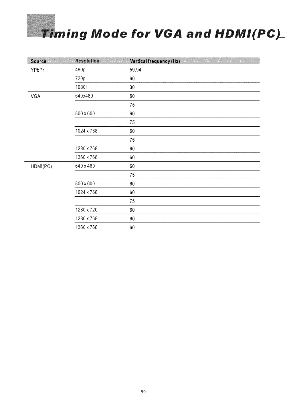
"g Mode for VGA and HDMI(PC
YPbPr 480p
720p
1080i
VGA 640x480
800x600
1024x768
1280x768
1360x768
HDMI(PC) 640x480
800x600
1024x768
1280x720
1280x768
1360x768
59.94
60
30
60
75
60
75
60
75
60
60
60
75
60
60
75
60
60
60
59
els Policy
SyntaxBrillian's D.O.A. Policy for LCD HDTVs for
Defective Pixels on LCD Panels
(Applicable to the LCD HDTV sold within USA & Canada only)
LCD HDTVs are evaluated at a distance of approximately 50 centimeters
(approximately 20 inches) between the LCD panel and the eyes of the user at a
90 degrees viewing angle. All LCD panels have been tested to ensure they
comply with our factory standards. Our evaluation is based on the number of
defective pixels and the distance between any two defective pixels. Bright dots
are dots that appear bright and unchanged in size when a LCD HDTV screen
displays under a black pattern; dark dots are dots that appear dark and
unchanged in size when a LCD HDTV screen is displayed under pure red, green,
or blue patterns ("defective pixels"). Adjacent dots are dots located directly
next to each other.
Customers are required to check their LCD panel immediately after purchase.
To identify defective pixels, the LCD panel should be examined under normal
operating conditions as mentioned above, preferably in its native display
resolution, and with a 90 degrees viewing angle.
A LCD HDTV will be considered dead on arrival (D.O.A.) with regards to defective
pixels on the LCD panel when any one of the following criteria is met:
_ Atotal of 7 defective pixels including both bright dots and dark dots are
present (the typical 30" LCD Television screen has 1 million pixels), or
_ 2 or more pairs of adjacent bright dots are present, or
_ 3 adjacent bright dots are present, or
_#3 adjacent dark dots are present.
In view of customers' concerns about dead pixels, SyntaxBrillian would like to address
that defective pixels are not ultimately avoidable with the current LCD industry
standard panel manufacturing processes. We always strive to improve our technology
and minimize the chance of occurrence of defective pixels by applying strict screening
processes in our factory production processes.
However, SyntaxBrillian cannot guarantee that a return unit to our customers will be
100% free of defective pixels.
For questions, please call our toll free service number in the USA at 888-Syntax-Brillian-8.
"At Syntax-Brillian Corporation, a satisfied customer is our
most important focus."
6O
Y
3:2 pull down = Process of converting 24 frames per second film to video by repeating one film frame
as three fields, then the next film frame as two fields.
11122 11122
480I = 480 lines of display every 1/60 of a second; image is displayed by interlace scanning. See
also Interlaced
4BOP = 480 lines of display every 1/60 of a second; image is displayed by progressive scanning, See
also Progressive.
720P - 720 lines of display every 1/60 of a second; image is displayed by progressive scanning, See
also Progressive,
1OBBI = 540 lines of display x 2 every 1/30 of a second; image is displayed by interlace scanning,
See also Interlaced
16.'9 =Aspect ratio under Hi Def. and theater movie formats, Also known as widescreen; see Aspect
Ratio
4_3 = Aspect ratiounder SDTV; see Aspect Ratio
Active Matrix TFT (Thin Film Transfer) - A type of display technology where the three primary
colors are modulated. Results in better contrast ratios suitable for video.
Alarm = Feature on the Syntax=Brillian Olevia models. Allows the unit to power on from the stand by
mode.
Alarm Time = Time specified as to when the unit will power on. See Alarm.
Aspect Ratio = The ratio of an image according to the width and height of a picture.
ATSC = Advanced Television Systems Committee; international, non=profit organization that is
committed to developing standards for digital television.
Reference: http ://www.atsc.org
Bezel = Refers to the plastic or metal frame that acts like a shell around the LCD glass.
Backlight = Refers to the component, that lights up the LCD display.
Balance = Feature on the OSD for the Syntax=Brillian Olevia models that adjust the left and right
sound output from the speakers.
Background = Feature on the OSD for the Syntax=Brillian Olevia models, which allows the user to
change the OSD background, display to transparent or opaque.
Brightness - The measurement of color that is illuminated. Colors range from black to white.
CATV = Community Antenna Television (Cable Television)
Channel Favorite = Feature on the OSD for the Syntax=Brillian Olevia models that allows the user to
scroll through a defined list of channels that the user sets up.
Channel Edit = Feature on the OSD for the Syntax=Brillian Olevia models that allows the user add or
delete a channel.
Channel Source = Feature on the OSD for the Syntax=Brillian Olevia models that lets the user select
the source of their channels. Select TV for antennae or CATV for cable television.
Channel Auto Scan - Feature on the OSD for the Syntax-Brillian Olevia models that when initiated,
will determine which channels are available and which arenot= If a desired channel is not accessible,
you can add the channel in manually. See Channel Edit.
Channel Fine Tune = Feature on the OSD for the Syntax=Brillian Olevia models that enables the user
to tune the channel for better reception.
Chroraa = (Chrominance) Refers to the color characteristics of a video signal.
CC = Closed Caption
61
Glossary
Color - The term refers to the amount of color present. This varies between each user, as each
person perceives colors differently.
Color Temperature - Feature on the OSD for the Syntax-Brillian Olevia models that enables warm,
normal or cool color settings. Warm emphasizes red, cool emphasizes blue, and normal doesn't
emphasize any of the primary colors. This setting may affect each person individually depending on
how color is perceived.
Comb Filter - A filtering system designed to removal unwanted artifacts by rejecting certain
frequencies while permitting others.
Component - A three RCA type input that uses high quality cables (one for brightness, and two for
color). Process increases bandwidth resulting in more color information to be carried to theTV
producing a more accurate picture.
Composite - Also known as CVBS, Technology that permits the combination of color information and
brightness under one wire. A single video signal that carries both brightness and color information
are contained in a single wire.
Contrast - Difference in luminance between the white and black colors.
CRT - Cathode Ray Tube.
DB15 - Also referred to as VGA; See VGA
De-Interlace - Process of converting an interlaced video signal.
Display Area - The perimeter of the LCD glass the image is displayed on. See Video Resolution
Dual Link- See Single Link; Supportsa maximum bandwidth of 2x 165 MHz (1920x 1080@60Hz,
1280 x 1024 @ 85 Hz).
DVI- Digital Video Interface Describes the technology that is used to take full advantage ofasignal
when paired with a high-end video card and flat panel displays
DVI-A - Digital Video Hi-Resolution Analog
DMI-D- Digital Video Interface Digital; Cable is used for direct connection from one digital source
to the TV; See DVI
DVI-I-DigitaIVideoInterface Integrated; Cable that supports analog and digital signals; SeeDVI
DTV - Digital Television
Factory Default - Feature on the OSD for the Syntax-Brillian Olevia models that resets all menu options
to factory default.
F-Connector - The standard connector found on video equipments that coaxial cables connect to.
Flat-Panel Display - ultra thin displays, usually found in notebooks are now entering the TV
appliances sector as new technology enables wider/larger screens.
Frame - A complete picture that includes both even and odd lines. 30 video frames are present in 1
second.
Gain - Describes the amplification level of a particular signal.
HDCP - High bandwidth Digital Content Protection
HDTM - 1.High Definition Television 2. Designates as the unit having a built in ATSC tuner to decode
High Definition signals (720P/1080I).
HD-Ready - A unit that supports the High Definition displays (720P/1080I) with the help of a Set-Top Box.
Horizontal Resolution - Refers to the number of vertical black and white lines defined along a horizontal
line.
IR - Infrared
Input - term used in the On Screen Display
62
Glossary
Interlaced - Images are the result of lines of data reassembled. Interlaced refers to the process
of an image's odd lines reassembled from top to bottom taking about 1/60 of a second, before
reassembling the even lines which results in a full picture. Antonym: Progressive
Language - Feature on the OSD for the Syntax-Brillian Olevia models that enables the OSD to be
read in different languages.
LCD - Liquid Crystal Display
LCoS - Liquid Crystal on Silicon
LED - Light Emitting Diode
Luminance - refers to the brightness of an image.
Lux - 1 Lux = 1 footcandle; measurement of brightness
Moire - A visual illusion in which a succession of parallel curved lines produces a pattern to the
naked eye, but does not really exist. Otherwise known as the moire effect.
NCTA - National Cable Television Association
Noise reduction - Feature on the OSD for the Syntax-Brillian Olevia models that enables channels
from the tuner box to reduce noise displayed on the LCD unit.
NTSC - National Television systems Committee
OSD - On Screen Display; brought up by pressing the menu button on the TV or the Remote.
Over Scanning - An image displayed is larger than the display area
PAL - Phase Alternating Line
Parental Control - The ability to block access to specified content from an unsuitable audience.
PIP - Picture in Picture; feature that enables one source to be displayed on top of another source,
Pixel Resolution - Refers to the number of rows horizontal and vertical that produces the image,
PIP - Picture in Picture; Allows an image to be displayed in front of another image,
Plug and Play - Describes the hardware or software that is installed and does not require any
configuration before using.
Progressive - An image or lines of data that is reassembled from top to bottom sequentially.
Antonym: Interlaced
RGB- Red, green&blue These primary colors provide the basis for many different colors.
Refresh Rate - Refers to the maximum number of frames that the monitor can display per second.
Usually measured in hertz.
Saturation - The amount of a particular color present in an image.
SCART - An industry standard for interconnecting audio-video equipment developed by Peritel.
Usually associated with PAL video equipment.
SDTV - Standard Definition Television usually in 4801/P format.
SECAM - Sequential Color with Memory or Sequential Couleur Avec Memoire
Set-Top-Box - box that is capable of receiving and decoding digital transmissions (i.e. High
Definition Cable Box, Digital Cable box).
Sharpness - Tries to artificially enhance the edges of a picture.
Single Link - supports a maximum bandwidth of 165 MHz
(1920 x 1080 @ 60 Hz, 1280 x 1024 @ 85 Hz).
Split screen - Feature that places two images side by side.
1 2
63
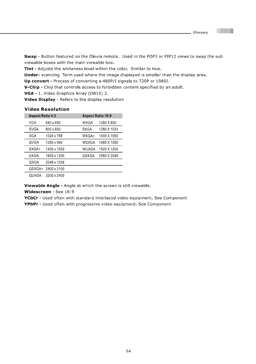
Glossary
Swap- Button featured on theOlevia remote. Used in the POP3 or PIP12 views to swap the sub
viewable boxes with the main viewable box.
Tint - Adjusts the whiteness level within the color. Similar to Hue.
Under- scanning Term used where the image displayed is smaller than the display area.
Up convert - Process of converting a 480P/I signals to 720P or 1080I.
V-Chip - Chip that controls access to forbidden content specified by an adult.
VGA - 1. Video Graphics Array (DB15) 2.
Video Display - Refers to the display resolution
Video Resolution
VGA 640 x480 WXGA 1280X800
SVGA 800x600 SXGA 1280X 1024
XGA 1024 x 768 WXGA+ 1400 X 1050
QVGA 1280 x960 WSXGA 1680 X 1050
SXGA+ 1400 x 1050 WUXGA 1920 X 1200
UXGA 1600 x 1200 QSXGA 2560 X 2048
QXGA 2048 x 1536
QSXGA+ 2800 x 2100
QUXGA 3200x2400
Viewable Angle - Angle at which the screen is still viewable.
Widescreen - See 16:9
YCbCr - Used often with standard interlaced video equipment. See Component
YPbPr - Used often with progressive video equipment. See Component
64
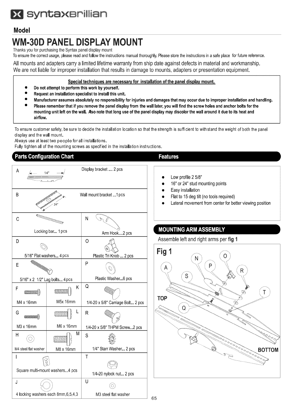
Model
WM-30DPANELDISPLAYMOUNT
Thanksyou forpurchasingthe Syntaxpaneldisplaymount
Toensurethecorrectusage,pleasereadandfollowthe instructionsmanualthoroughly.Pleasestorethe instructionsina safeplace forfuturereference.
All mountsandadapterscarrya limitedlifetimewarrantyfromshipdate againstdefectsinmaterialandworkmanship.
Wearenot liablefor improperinstallationthatresultsin damageto mounts,adaptersor presentationequipment.
Special techniquesare necessaryfor installation of the panel display mount.
• Donot attemptto performthisworkby yourself.
• Requestaninstallationspecialistto installthis unit.
•Manufacturerassumesabsolutelynoresponsibilityfor injuriesanddamagesthat mayoccurdueto improperinstallationand handling.
•Pleaserememberthat if youremovethe paneldisplayfrom thewalllater,youwillfind thescrewholesandanchorboltsfor the
mountingunitleft onthewall. _lso notethat longuseof the paneldisplaymaydiscolorthewallaroundit dueto itsheatand
airflow.
Toensure customer safety, be sure to decide the installation location so that the strength is sufficient to withstand the weight of both the panel
display and the wall mount.
Always useat least two people for all installations.
Fully tighten all of the mounting screws as specified in the installation instructions.
A,,_ 14" _;,is
• - . o -e./-
Displaybracket.... 2 pcs
// 24"
Lockingbar...1pcs
5t16" Flatwashers...4 pcs
5116"x 2 1/2"Lagbolts...4pcs
F
M4x 16mm
G
M3x 16mm
H
M4steelflatwasher
I
M5x16mm
M6 x 16mm
M
M8x 16mm
Wallmountbracket...1pcs
ArmHook....2pcs
0
PlasticTriKnob... 2 pcs
PlasticWasher...6pcs
114-20x 5t8"CarriageBolt... 2 pcs
114-20x518"THPMScrew...2pcs
S
1t4"StarrWasher...2pcs
T
Squaremulti-mountwashers...4pcs 114-20nylocknut...2 pcs
J U
4 lockingwasherseach8mm,6,5,4,3 M3 steel flatwasher
• Low profile 2 5!8"
• 16"or 24" stud mounting points
• Easy installation
• Flat to 15 deg tilt (no tools required)
• Lateral movementfrom center for better viewing position
Assembleleftandrightarmsperfig 1
Fig 1 ..
f -\ f-\
BOTTOM
65
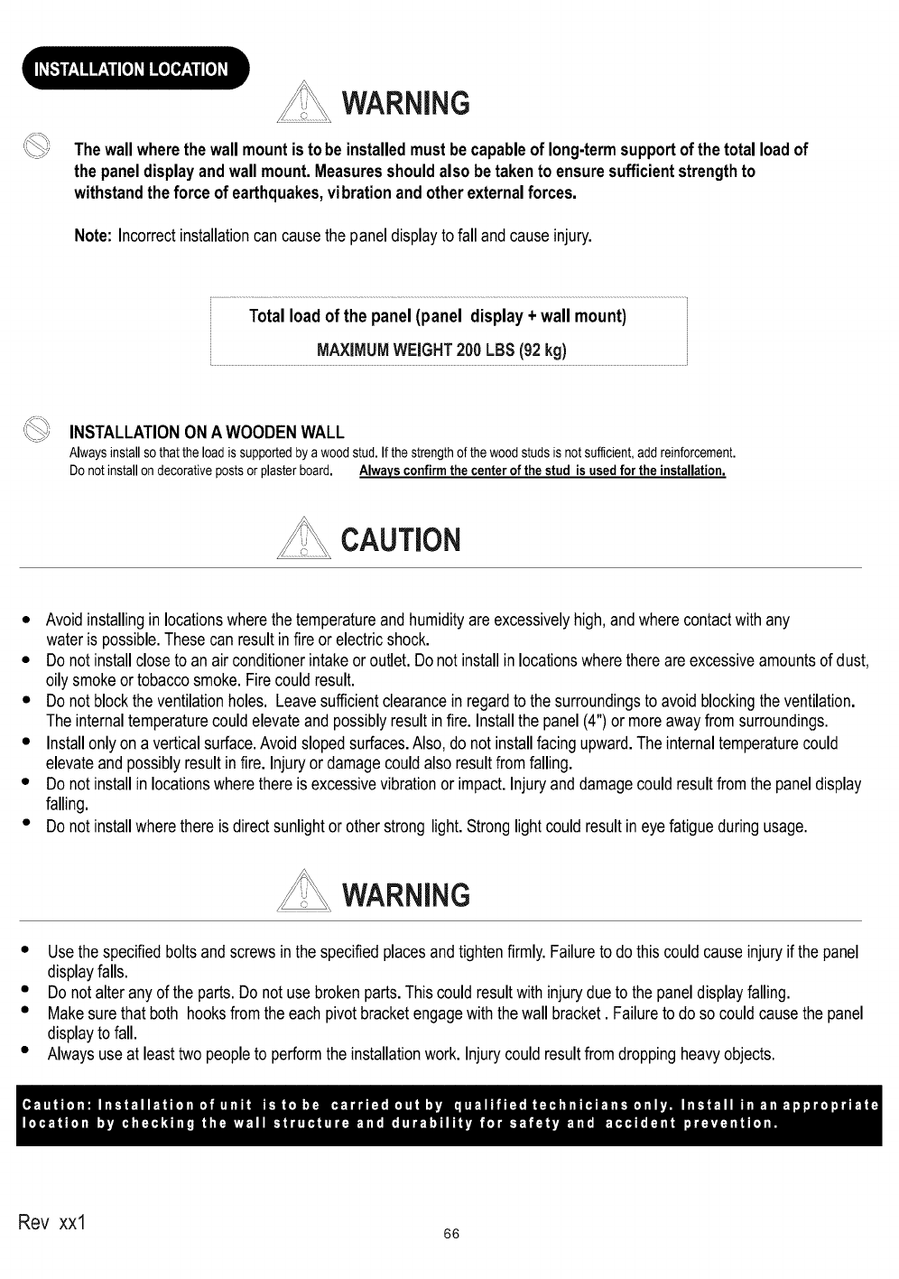
WARNING
Thewallwherethewallmountisto be installedmustbe capableof long-termsupportofthe totalloadof
the paneldisplayandwallmount.Measuresshouldalso betakento ensuresufficientstrengthto
withstandthe force of earthquakes,vibrationandotherexternalforces.
Note: Incorrectinstallationcan causethe paneldisplayto fall andcauseinjury.
Totalload of the panel(panel display+ wallmount)
MAXIMUMWEIGHT200LBS(92kg)
INSTALLATIONONA WOODENWALL
Alwaysinstallso that the loadissupportedbya wood stud.If the strengthofthe wood studsis not sufficient,add reinforcement.
Do not installon decorativeposts orplasterboard. Always confirmthe center of the stud is used for the installation.
CAUTION
• Avoidinstallingin locationswherethe temperatureand humidityare excessivelyhigh,andwherecontactwithany
wateris possible.Thesecan resultinfire or electricshock.
• Do not installcloseto anairconditionerintakeor outlet.Donot installin locationswherethereareexcessiveamountsof dust,
oily smokeor tobaccosmoke.Firecouldresult.
• Do not blockthe ventilationholes. Leavesufficientclearancein regardto thesurroundingsto avoid blockingtheventilation.
The internaltemperaturecouldelevateand possiblyresultinfire. Installthe panel(4")or moreawayfromsurroundings.
• Installonlyon averticalsurface.Avoidslopedsurfaces.Also,do notinstallfacingupward.Theinternaltemperaturecould
elevateandpossiblyresultinfire. Injuryor damagecouldalsoresultfromfalling.
• Do not installin locationswherethereis excessivevibrationor impact.Injuryanddamagecouldresultfromthe paneldisplay
falling.
• Do not installwherethere is directsunlightorotherstrong light.Stronglightcouldresultineye fatigueduringusage.
WARNING
• Usethe specifiedboltsandscrewsinthe specifiedplacesandtightenfirmly.Failureto do thiscouldcauseinjuryif the panel
displayfalls.
• Do not alteranyof theparts.Do not usebrokenparts.Thiscouldresultwithinjurydueto the paneldisplayfalling.
• Makesurethat both hooksfromthe eachpivotbracketengagewith thewall bracket. Failureto do socouldcausethe panel
displayto fall.
• Alwaysuse at leasttwopeopleto performthe installationwork. Injurycouldresultfromdroppingheavyobjects.
Rev xxl 66
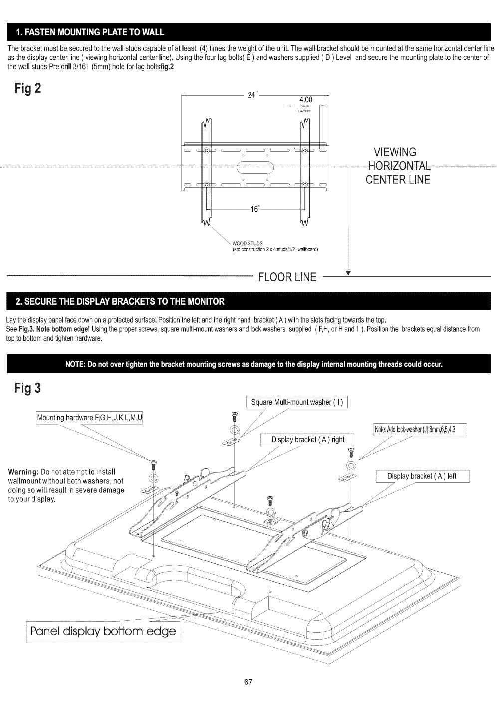
The bracketmust be securedto the wall studscapableof at least (4) timesthe weightof the unit. Thewall bracketshouldbe mountedat the same horizontalcenterline
as the displaycenterline( viewinghorizontalcenterline). Usingthe four lag bolts( E ) andwasherssupplied( D ) Level and securethe mountingplateto the centerof
the wallstuds Pre drill 3/161 (5ram)holefor lag boltsfig.2
Fig 2 24" 4.00
_PACI_G
i
.........................................................................................................................................................................................................................................._................................]t....................................................
cSS cZo)_
16'
VIEWING
........................................HORIZONTAL..................................................................
CENTER LINE
WOOD STUDS
(std construction 2 x 4 studs/l/2i wallboard)
FLOOR LINE v
Laythe displaypanelfacedownon a protectedsurface.Positiontheleftandtherighthandbracket(A )withtheslotsfacingtowardsthe top.
SeeFig.&Notebottom edge!Usingtheproperscrews,squaremulti-mountwashersandlockwasherssupplied( F,H,orHandI ). Positionthe bracketsequaldistancefrom
topto bottomandtightenhardware.
Fig 3
SquareMuiii:mountwasheri ii ]
MountinghardwareF,G,H,J,K,L,M,U
Warning: Do not attempt to install /_
wallmount without both washers, not
doing so will result in severe damage
to your display.
,,__, Note:Add10ck-washer(J)8mm,6,5,4,3
Displaybracket(A ) right3 .................
|
_ Displaybracket(A ) left
Panel display bottom edge
67
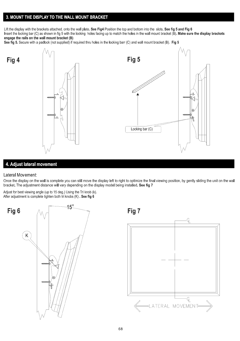
Liftthedisplaywiththebracketsattached,ontothewallplate.See Fig4 Positionthetop and bottomintothe slots.Seefig 5and Fig 6
insertthe lockingbar (C) asshownin fig 5 with the locking holesfacing up tomatch the holesin the wall mount bracket(B).Makesure the dispJaybrackets
engage the rails on the wall mount bracket (B)
Seefig 5. Securewith apadlock (notsupplied)if requiredthru homesin the mockingbarr (C)and wall mountbracket(B). Fig 5
Fig 4 "V' Fig 5
J
_,,//\/
V
LateralMovement:
Once the display on the wail is complete you can still movethe display left to right to optimize the finaJviewing position, by gently sliding the unit on the wall
bracket. The adjustment distance will vary depending on the display model being installed. See fig 7
Adjust forbestviewingangle (upto 15 deg.) Usingthe Triknob(k).
After adjustmentis completetightenbothtri knobs(K). Seefig 6
Fig 6Fig 7
[ A,TER,_I iv1,,_,,Er,J/EN
68

/
/
69

_:::_ L_ IE_ "%f II A TM
Syntax-Brillian Corporation
20480 East Business Parkway
City of Industry, California 91789 USA
1-866-9-OLEVlA
