Olevia 247TFHD User Manual LCD TELEVISION Manuals And Guides L0803401
OLEVIA LCD Television Manual L0803401 OLEVIA LCD Television Owner's Manual, OLEVIA LCD Television installation guides
User Manual: Olevia 247TFHD 247TFHD OLEVIA LCD TELEVISION - Manuals and Guides View the owners manual for your OLEVIA LCD TELEVISION #247TFHD. Home:Electronics Parts:Olevia Parts:Olevia LCD TELEVISION Manual
Open the PDF directly: View PDF ![]() .
.
Page Count: 71
2 SERIES
LCD HDTVs
OL_ _--VIA
242T FHD
247T FHD
252T FHD
255T FHD
USER
MANUAL
of Contents
Important Information ...................................................................................................... 1
Important Safety Precautions .................................................................................... 2
introducing the OLEVIA TV ................................................................................... 5
Accessories .................................................................................................................................... 7
TV Installation And Connection Guide
Identifying Front Controls and Rear Panels ...................................................................... g
- Descriptions of Connector Types ......................................................................................... 10
- Turn the power on the TV ........................................................................................................ 11
Installation ................................................................................................................................................. 12
- Connecting to an Antenna or Video Equipment with Antenna Outlet ........................ 13
- Connecting to a Set-Top-Box with HDMI Cables ....................................................................... 14
- Connecting to a Satellite Receiver or Cable Box with Component Connectors 15
- Connecting to a DVD Player with A/V or S Video Cables .............................................. 16
- Connecting to a DVD Player with Component Cables ..................................................... 17
- Connecting to a DVD Player with HDMI Cables ....................................................................... l g
- Connecting to a Satellite Receiver or Cable Box with A/V Cables .............................. l P
- Connecting to a VCR, PVR, or DV with A/V Cables .......................................................................20
- Connecting to a Blue-Ray DVD Player or HD-Receiver with HDMI Cables and a
PC with VGA Cables ...................................................................................................................... 21
- Connecting to a D-VHS with HDMI Cables ............................................................... 22
- Connecting to a D-VHS with Component Cables ....................................................... 23
- Connecting to an Audio Receiver ..................................................................................... 24
- Connecting to a Home Theater System or Earphone Set .................................. _?_5
- Instruction for Uploading New Firmware ............................................................ 26
Remote Control Guide
Remote Function Keys & Description 27
Programming the Remote Control ............................................................................ 2g
Battery Installation 29
On Screen Display (OSD) 30
Introduction ........................................................................................................................ 30
Operating in the OSD .......................................................................................................... 30
Initial Screen ........................................................................................................................... 3]
PICTURE OSD Adjusting TV Picture Settings .......................................................... 32
- Description of Settings .......................................................................................... 32
- Selecting the Picture Mode ....................................................................................... 33
- Adjusting the Picture Quality .............................................................................. 35
AUDIO OSD Adjusting Sound Quality ................................................................... 37
- Description of Settings ............................................................................................ 37
- Adjusting the Audio Settings .................................................................................... 37
- MTS System for Stereo TV 3g
SCREEN OSD Adjusting Screen Modes ................................................................... 39
- Description of Settings ................................................................................................ 39
- Changing the Screen Mode ........................................................................................ 39
- Selecting the Picture/Video Source ..................................................................... 43
SETUP OSD Adjusting Personal TV Settings ......................................................... 44
- Description of Settings 44
- Searching the TV Channels 45
- Editing Channels ............................................................................................................ 46
- Closed Caption Options ........................................................................................ 50
- Setting up Parental Control Password .............................................................. 51
- Activating the Parental Control Feature ................................................................ 51
- Resetting the Password ........................................................................................... 57
- Setting the Date and Time .................................................................................... 5g
- Setting the TV Timer 59
- Timeout Settings for OSD Menu 59
- TV OSD Languages 60
- Setting DPMS 60
- Setting LED Light ....................................................................................................... 60
- Factory Default Option .......................................................................................... 60
- Displaying the Firmware Version .......................................................................... 60
Specifications ................................................................................................................. 6]
Timing Mode for VGA and HDMI(PC) ................................................................... 63
Pixels Policy 64
Glossary 65
lnforma#ion
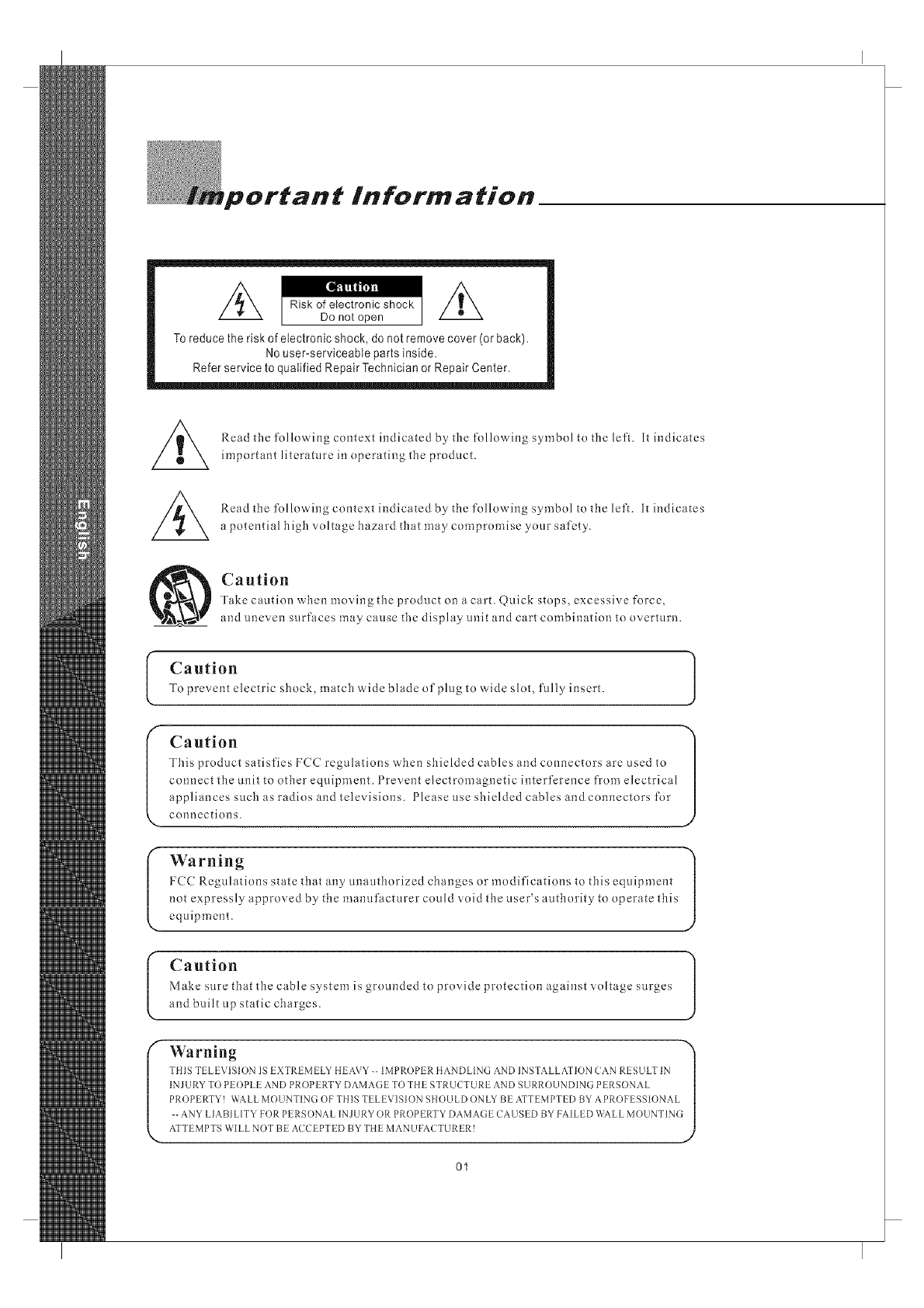
Toreduce the risk of electronic shock, do not remove cover (or back),
No user-serviceable parts inside,
Refer service to qualified Repair Technician or Repair Center,
Read the following context indicated by tile following symbol to the left. It indicates
important literature in operating the product.
Read the following context indicated by the following symbol to the left. It indicates
a potential high voltage hazard that may compromise your safety.
Caution
Take caution when moving the product on a cart. @.tick stops, excessive force,
and uneven surfaces may cause the display unit and cart combination to overturn.
(
I"
Caution
To prevent electric shock, match wide blade of plug to wide slot, fully insert.
Caution 1
This product satisfies FCC regulations when shielded cables and connectors are used to
) y
connect the unit to other equipment. 1 revent electromagnetic interference from electrical
appliances such as radios and televisions. Please use shielded cables and connectors for
connections.
Warning 1
Izcc Regulations state that any anaathorized changes or modifications to this equipment
not expressly approved by the manufacturer could void the user's authority to operate this
equipment.
Caution
Make sure that the cable system is grounded to provide protection against voltage surges
and built up static charges.
Warning "_
PROPEP, TY! WALL MOUNTIN(] OF THIS TELEVISION SHOULD ONLY BE ATTEMPTED BY APROFESSIONAL |
-- ANY LIABI LITY FOR PERSDNAL INJURY OR PROPERTY DAMAGE CAUSED BY FAILED WALL MOUNTING|
ATTEMPTSWILLNOTBE ACCEPTEDBYTHEMANUFACTURER! d
01
Fportan t Safe ty Precautions.
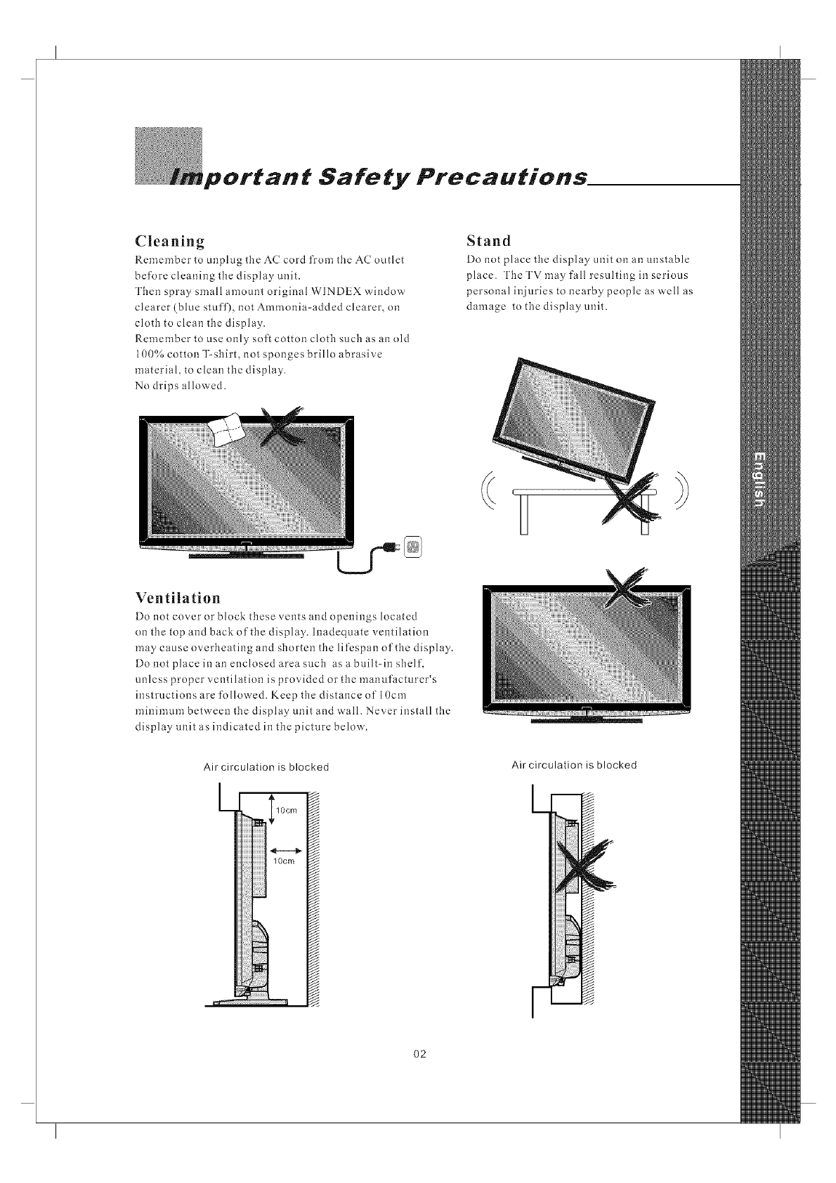
Cleaning
Remember to unplug the AC cord from the AC outlet
before cleaning tile display unit.
Then spray small amount original WINDEX window
clearer (blue stuff), not Ammonia-added clearer, on
cloth to clean the display.
Remember to use only soft cotton clotb such as an old
100% cotton T-shirt, not sponges brillo abrasive
material, to clean the display.
No drips alloa ed.
Stand
Do not place tile display unit on an unstable
place. The TV may fall resulting in serious
personal injuries to nearby people as well as
damage to the display unit.
Ventilation
Do not cover or block these vents and openings located
on tile top and back of the display. Inadequate ventilation
may cause overheating and shorten the lifcspan of the display.
Do not place in an enclosed area such as a built-in shelf,
unless proper ventilation is provided or the manufacturer's
instructions are followed. Keep tile distance of 10cm
minimum between the display unit and wall. Never install the
display unit as indicated in the picture below.
Air circulation is blocked
L ,&
I lOcm
w
lOcm
ili!!
i
_ Eiiiiiiiiiii
Air circulation is blocked
O2
Important Safety Precautions,
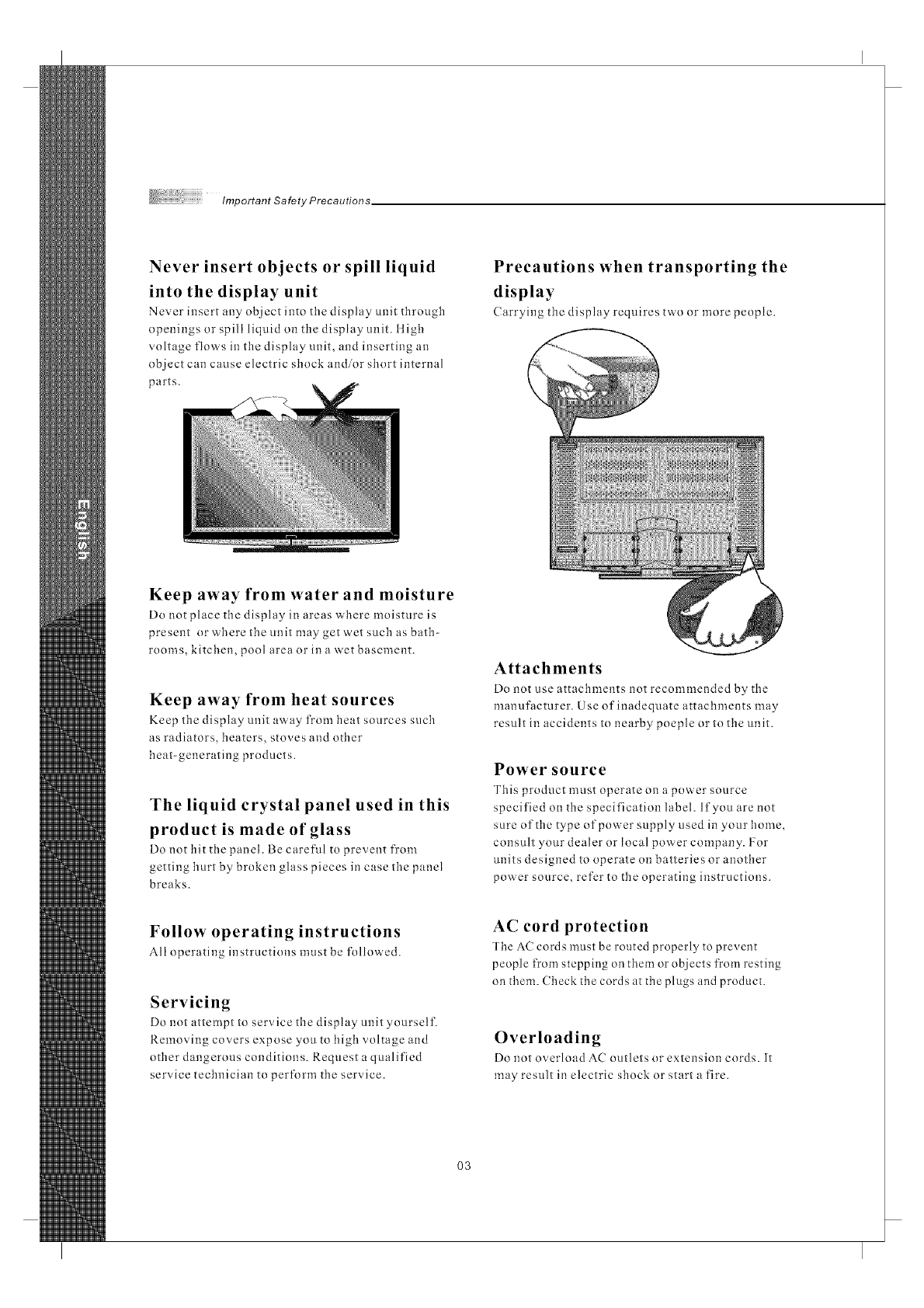
Never insert objects or spill liquid
into the display unit
Never insert any object into tlle display unit through
npenings or spill liquid on tile display unit. ltigh
voltage flows in tile display unit, and inserting an
object can cause electric shock and/or short internal
parts.
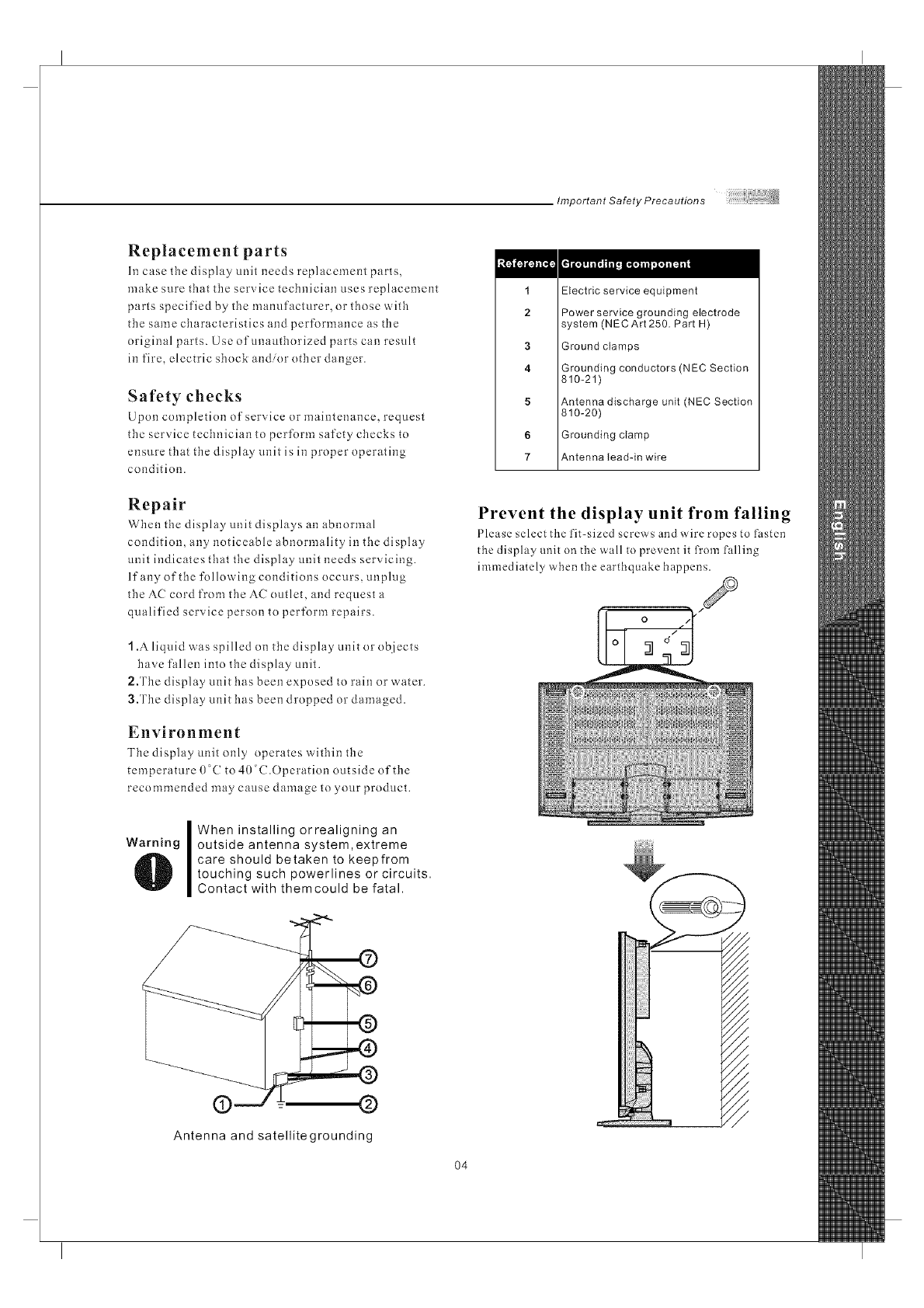
Precautions when transporting the
display
Carrying the display requires two or more people.
Keep away from water and moisture
Do clot place the display in areas where moisture is
present or'ahere the unit may get wet such as bath-
rooms, kitchen, pool area or in a wet basement.
Keep away from heat sources
Keep the display unit away from heat sources such
as radiators, beaters, stoves and other
heat-generating products.
The liquid crystal panel used in this
product is made of glass
Do not tilt tile panel. Be careful to prevent from
getting hurt by broken glass pieces in case the panel
breaks.
Attachments
Do not use attachments clot recommended by the
manufacturer. Use of inadequate attachments may
result in accidents to nearby poeple or to the unit.
Power source
This product must operate on a power source
specified on tile specification label. If you are clot
sure of the type of power supply used in your home,
consult your dealer or local power company. For
units designed to operate on batteries or another
power source, refer to the operating instructions.
Follow operating instructions
All operating instructions must be followed.
Servicing
DO not attempt to service the disphly unit yourself.
Removing covers expose you to high voltage and
other dangerous conditions. Request a qualified
service technician to pertbrm the service.
AC cord protection
The AC cords must be routed properly to prevent
people from stepping on them or objects from resting
on them. Check tile cords at tile plugs and product.
Overloading
Do clot overload AC outlets or extension cords. It
may result in electric shock or start a fire.
O3
Important Safety Precautions
Replacement parts
In case tbe display unit needs replacement parts,
make sure tbat the service technician uses replacement
parts specified by the manufacturer, or those with
the same characteristics and performance as the
original parts. Use ofunautborized parts can result
in fire, electric sbock and/or other danger.
Safety checks
Upon completion of service or maintenance, request
the service technician to perform safety cbccks to
ensure that tbe display unit is in proper operating
condition.
Repair
Wben the display unit displays an abnormal
condition, any noticeable abnormality in the display
unit indicates that the display unit needs servicing.
If any of the following conditions occurs, unplug
the AC cord from the AC outlet, and request a
qualified service person to perform repairs.
1.Aliquid was spilled on tbe display unit or objects
have fallen into tbe display unit.
2.Tbe display unit has been exposed to rain or water.
3.The display unit has been dropped or damaged.
Environment
Tbe display unit only operates within the
temperature 0 ( to 40°C.Operation outside of the
recommended may cause damage to your product.
Warning
IWheninstallingorrealigningan
outside antenna system, extreme
care should betaken to keepfrom
touching such powerlines or circuits.
Contact with themcould be fatal.
1
2
3
4
5
6
7
Electric service equipment
Power service grounding electrode
system (NECArt 250. Part H)
Ground clamps
Grounding conductors (N EC Section
810-21)
Antenna discharge unit (NEC Section
810-20)
Grounding clamp
Antenna lead-in wire
Prevent the display unit from falling
Please select the fit-sized screws and wire ropes to l._sten
the display unit on the wall to prevent it from falling
immediatePy when the earthquake happens.
(9 @
Antenna and satellitegrounding
O4
the OLEVIA TV
Welcome!
Thank you forpurchasing a OLEVIALCD tlDTV.
This manual isto be usedwith the followingmodel:
OLEVIA 2Series
This manual isdesigned to helpyou through settingup and operatingyour
LCD tlDTV asquickly as possible. The model and serial numbersarc on the
back coverofyourTV. Write thesenumbersinthespaceprovidedinthis
manual for yourrecords. Please readall the safctyand operating instructions
carefully, andkeep this manualfor future reference.
Licensed Under U.S. Patent 4930160.
Owner's Record
The model andserial numbers arelocated at therear of thedisplay
unit, or onthe side of the media receiverunit on thecartons
(white label). Record these numbers in the spaces provided below.
And register yourproduct at www.olevia.com. Refer to them
whenever you call Syntax-Brillian Corporation orlocal dealer
regarding this product.
Model No.
Serial No.
\
05
Introducing the Ole via TV
OLEVIALCDliDTVincludesmanyfeamres, youwill enjoy throughout
the usage of your TV. These highlightedfeatures include:
Fully Integrated ItDTV(IIigh Definition TV):
[IDTV delivers astunning picture farbeyond the quality of standard
televisions. Theseprograms offer crystal clear videowith amazing
detail played withenhanced audio qualityof digital televisionprograms.
Youcan eujoy bettersound and picturein movies, primetime TVshows,
and other [{Dbroadcasts iu dynamictelevisiou settiugs throughcable,
satellite or even free broadcasts overthe air.
ItDMI (ltigh DefinitionMultiniedia Interface):
The next generation of DVI, tlDMlprovides the bestinterface between
a DVD playerand compatible productssuch as digitalset top box for
uucompressed digital audioivideoconnections. When matchedwith a
OLEVIATV, multi-channel digital audio signals, uncompressed DVI
digital video andintercommunication between highmultimedia interfaces
are combined througha single interconnectingcable.
ItDMI and theltDMl logo are trademarks or registered trademarks of
IIDMI Licensing, LLC.
HDN-U TM
Stl_U t_E_INmON _U_T_fa_mA_T_R_,CE
Manufactured under license from Dolby Laboratories. Dolby and the
double-D symbol areregistered trademarks of Dolby Laboratories. r]['IlDOLBYI
DIGITAL
Olevia and theOlevia logo aretrademarks or registeredtrademarks of
Syntax-Brillian Corporation inthe United Statesand other countries.
Corporate names, trademarks, registered trademarks, service marks,
symbols, and logos stated herein areproperty of theirrespective companies.
O6
m
'CeSSO#'/e$
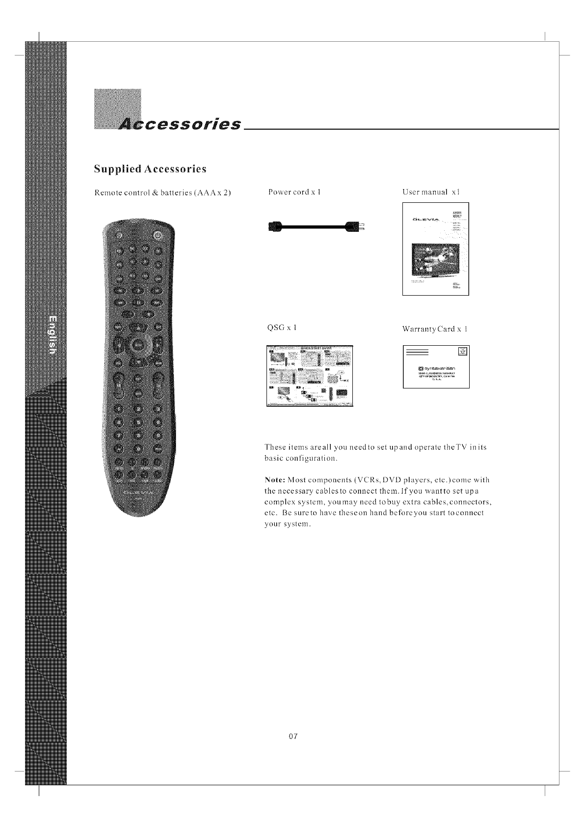
Supplied Accessories
Remote control &batteries (AAAx 2) Power cord x 1 User manual xl
QSG x 1 WarrantyCard x 1
These items areall you needto set upand operate theTV inits
basic configuration.
Note: Most components (VCRs, DVD players, etc.)come with
the necessary cablesto connect them. If you wantto set upa
complex system, youmay need tobuy extra cables,connectors,
etc. Besuretohavetheseonhandbeforeyou starttoconnect
your system.
07
Installation and Connection Guide__
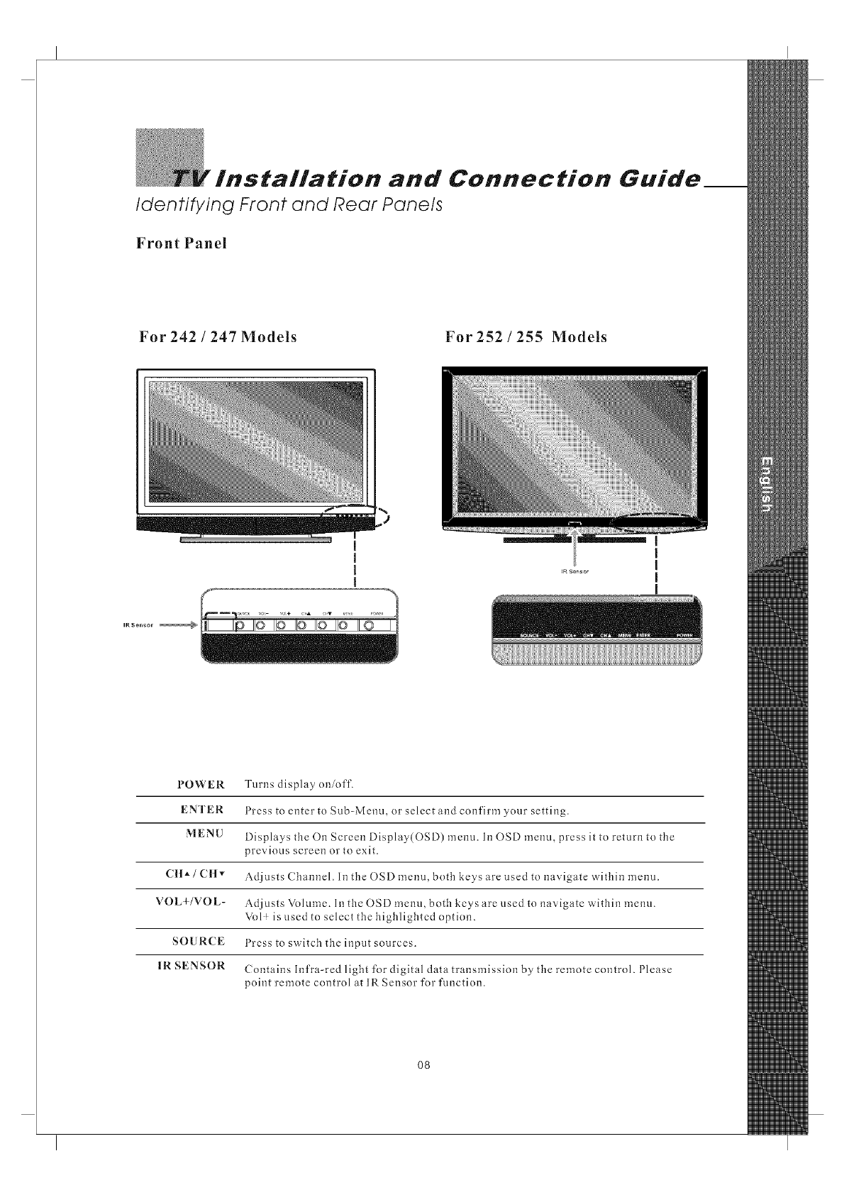
Identifying Front and Rear Panels
Front Panel
For 242 /247 Models For 252 /255 Models
t
I
I
IR Sensor _
POWER
ENTER
MENU
C lt */CHv
VOL+/VOL-
SOURCE
IR SENSOR
Turns display on/off.
Press to enter to Sub-Menu, or select and confirm your setting.
Displays the On Screen Display(OSD) menu. Ii10SD menu, press it to return to the
previous screen or to exit.
Adjusts Channel. In the OSD menu, both keys are used to navigate within menu.
Adjusts Volume. In the OSD menu, both keys are used to navigate within menu.
Vol ! is used to select the highlighted option.
Press to switch the input sources.
Contains Infra-red light for digital data transmission by the remote control. Please
point remote control at IR Sensor for function.
O8
TV Installation and Connection Guide
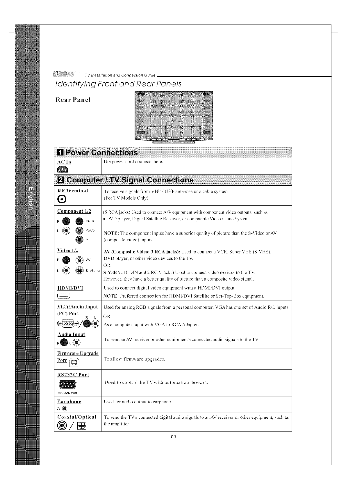
Identifying Front and Rear Panels
R e a r Pa n e I
_ The power cord connects here.
RF Terminal
®
Component 1/2
R O O Pr/Cr
L _ @Pb/Cb
Video 1/2
RO (_AV
L _ @S-Video
HDMI/DVI
VGA/Audio lnl_
Port R L
Audio Input
+OL®
Firmware Upgrade
Port @
RS232C Port
RS232C Port
_hone
Coaxial/Optical
®/[]
To receive signals from VIII: /UIIF antennas or a cable system
(For TV Models Only)
(5 RCAjacks) Used to connect AiV equipment with component sddeo outputs, such as
a DVD player, Digital Satellite Receiver, or compatible Video Game System.
NOTE: The component inputs have a superior quality of picture than the S-Video orAV
(composite video) inputs.
AV (Composite Video: 3 RCA jacks): Used to connect a VCR, Super VtlS (S-VIIS),
DVD player, or other video devices to the TV.
OR
S-Video : (1 DIN and 2 RCA jacks) Used to connect video devices to the TV.
However, they have a better quality of picture than a composite video signal.
Used to connect digital video equipment with a tIDMIiDVI output.
NOTE: Preferred connection t\)r HDM1iDVI Satellite or Set-Top-Box equipment.
Used t\)r analog RGB signals from a personal computer. VGA has one set of Audio RiL inputs.
OR
As a computer input with VGA to RCA Adapter.
To send an AV receiver or other equipment's connected audio signals to the TV
Toallow firmware upgrades.
Used to control the TV'aith automation devices.
Used fi)r audio output to earphone.
To send the TV's connected digital audio signals to anAV receiver or other equipment, such as
the amplifier
O9
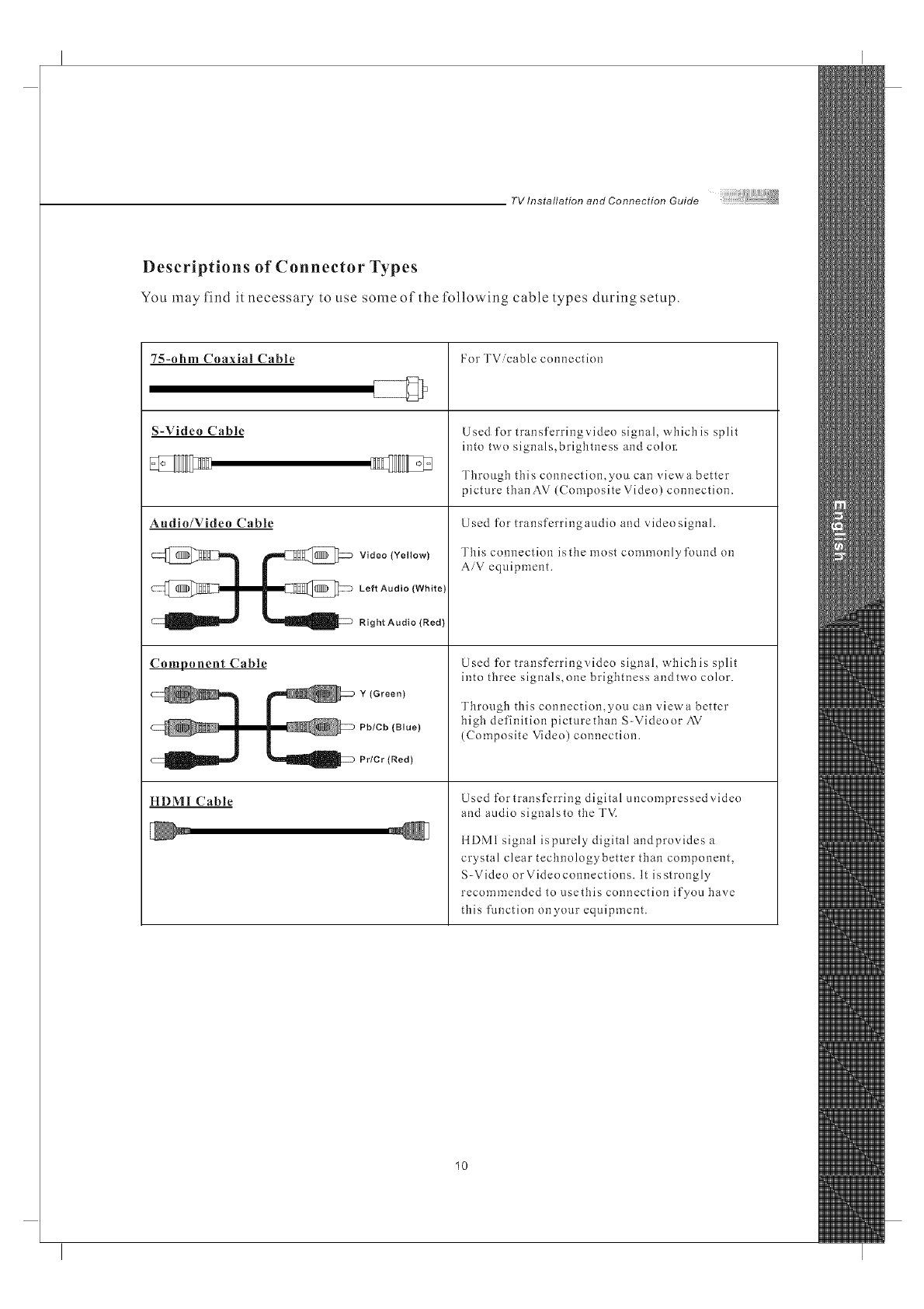
Descriptions of Connector Types
You may find it necessary to use some of the following cable types during setup.
7S-ohm Coaxial Cable
S-Video Cable
Audio/Video Cable
_-_ Video (Yellow)
@l l _@> LeftAudio(White)
_ Right Audio (Red)
Component Cable
l _ Pb/Cb (Blue)
_ Prier (Red)
HDMI Cable
For TVicable connection
Used for transferringvideo signal, which is split
into two signals,brigbtness and color:
Through this connection,you can vievva better
picture tban AV (Composite Video) connection.
Used for-transferringaudio and video signal.
Tbis connection isthe most commonly found on
AiV equipment.
Used for transferringvideo signal, which is split
into tbree signals,one brigbtness andtwo color.
Through tbis connection,you can viewa better-
high definition picturetban S-Videoor AV
(Composite Video) connection.
Used for transferring digital uncompressed video
and audio signalsto tbe TVi
ilDMI signal ispurely digital andprovides a
crystal clear technologybetter than component,
S-Video or Video connections. It is strongly
recommended to usethis connection if you have
tiffs flmction onyour equipment.
10
TV Installation and Connection Guide
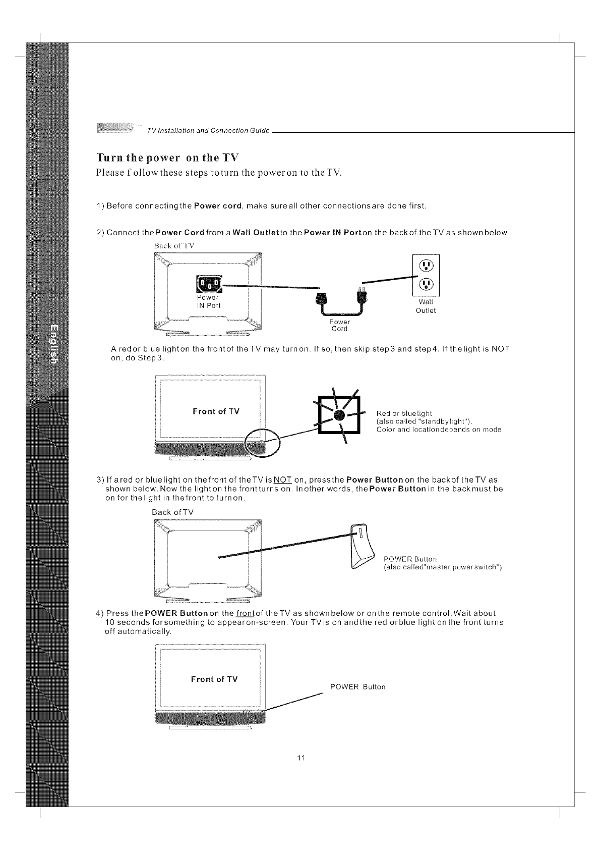
Turn the power on the TV
Please followthese steps toturn the poweron to theTV.
1) Before connectingthe Power cord, make sureall other connectionsare done first.
2) Connect the Power Cord from aWall Outlet to the Power IN Port on the back of theTV as shown below.
Back ot" TV
dip ....... _ Walt
Outlet
Power
Cord
A redor blue lighton the frontof theTV may turnon. If so, then skip step3 and step4. If thelight is NOT
on, do Step3.
Red or bluetight
(also called "standbylight").
Color and Iocationdepends on mode
3) If ared or blue light on thefront of theTV is NOT on, pressthe Power Button on the backof theTV as
shown below. Now the lighten the frontturns on. Inother words, thePower Button in the backmust be
on for thelight in thefronttoturnon.
Back of TV
POWER Button
(also called"master powerswkch")
4) Press the POWER Button on the front of theTV as shown below or on the remote control. Wait about
10 seconds forsomething to appearon-screen. Your TVis on andthe red orblue light on the front turns
off automatically.
Front of TV
POWER Button
Installation
TV Installation and Connection Guide
In the fullowing pages, you will find dlrectinns on how to install your tv and choice ofviden equipment.
@ Connecting to an Antenna or Video Equipment with Antenna outlet
@ Connecting to a Set-Top-Box with HDMI Cables (Preferred TV connection)
@ Connecting to a Satellite Receiver or Cable Box with Component Connectors
(Secondary Preferred after HDM1)
@ Connecting to a DVD Player with A/V or S Video Cables
@ Connecting to a DVD Player with Component Cables
@ Connecting to a DVD Player with HDMI Cables
@ Connecting to a Satellite Receiver or Cable Box with A/V Cables
@ Connecting to a VCR, PVR, or DV with A/V Cables
_Connecting to a Blue-Ray DVD Player or liD-Receiver with ItDMI Cables
and a PC with VGA Cables
@ Connecting to aD-VHS with HDMI Cables
@ Connecting to a D-VHS with Component Cables
@ Connecting to an Audio Receiver
@ Connecting to a Home Theater System or Earphone Set
@ Instruction for Uploading New Firmware
12
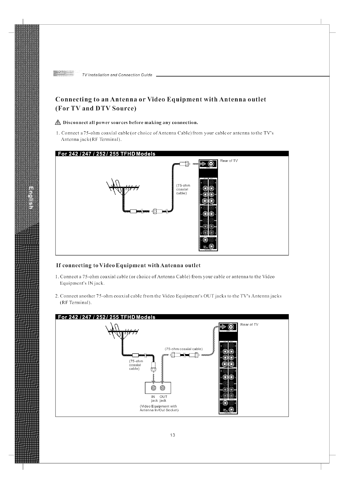
Connecting to an Antenna or Video Equipment with Antenna outlet
(For TV and DTV Source)
Disconnect all power sources before making any connection.
1. Connect a 75-ohm coaxial cable(or choice of Antenna Cable)from your cableor antenna tothe TV's
Antenna jack(RF Terminal).
ii¥ii,! !,,111,'_|llll,'l,'llll,'l,'ll diI I I i] _villll I1 _
(75-ohm
coaxial
cable)
RearofTV
If connecting to Video Equipment with Antenna outlet
1. Connect a 75-ohm coaxial cable (or choice of Antenna Cable) from your cable or antenna to the Video
Equipment's IN jack.
2. Connect another 75-ohm coaxial cable from the Video Equipment's OUT jacks to the TV's Antenna jacks
(RF Terminal).
ii,_ll,'_ l_|l,_ lllI!l,'l,_lI!l,'l,l di I Ii] _v_I111IIt.
IN OUT
jack jack
(Video Equipment with
Antenna In/Out Socket)
Rear of TV
13
TV Installation and Connection Guide
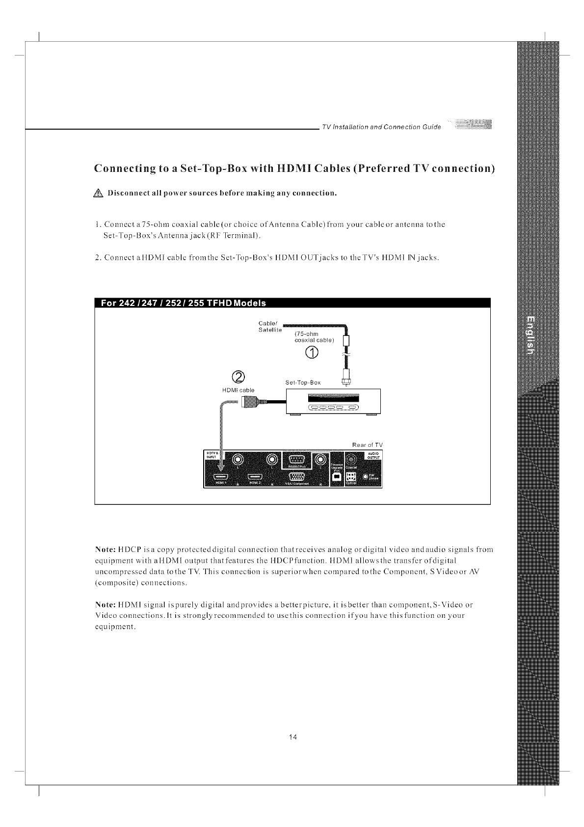
Connecting to a Set-Top-Box with HDMI Cables (Preferred TV connection)
Disconnect all power sources before making any connection.
1. Connect a75-ohm coaxial cable(or choice of Antenna Cable) fron_ your cableor antenna tothe
Set-Top-Box's Antenna jack (RF Termina 1).
2. Connect a IIDMI cable fromthe Set-Top-Box's IIDMI OUT jacks to theTV's IIDMI IN jacks.
Cable/
Satellite (75-ohm _
coaxial cable)
(9
(2) SetTo00ox
HDMI cable
Rear of TV
Note: ttDCP isa copy protectcddigital connection that receives analog ordigital video andaudio signals from
equipment with attDMI output thatfcatures the ttD(Pfunction, ttDMI allows the transfer of digital
uncompressed data to the TV. This connection is superiorwhen compared to the Component, S Video or AV
{composite) connections.
Note: ItDMI signal ispurely digital andprovides a betterpicture, it isbetter than component, S-Video or
Video connections. It is strongly recommended to use this connection if you have thisfmlction on your
equipment.
14
TV Installation and Connection Guide
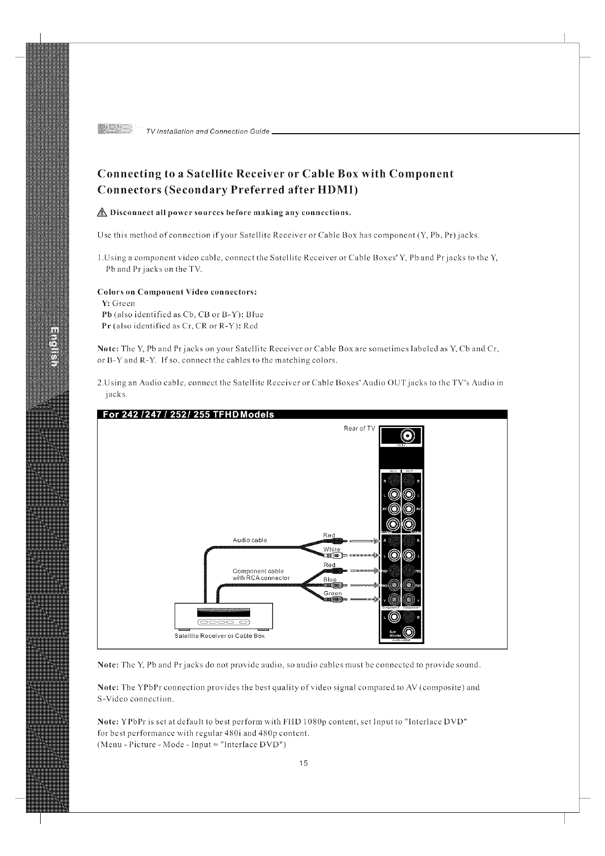
Connecting to a Satellite Receiver or Cable Box with Component
Connectors (Secondary Preferred after HDMI)
Disconnect all power snurces before making an)' cnnnections.
Use this method of connection if your Satellite Receiver or Cable Box has component (Y, Pb, Pr) jacks.
1.Using a component video cable, connect the Satellite Receiver or Cable Boxes'Y, Pb and Prjacks to the Y,
Pb and Prjacks on the TV.
(_nhlrs nn Compnnent Viden ennneetnrs:
Y: Green
Pb(also identified as Cb, CB or B-Y): Bhle
Pr (also identified as Cr, CR or R-Y): Red
} }
Nnte: The Y, 1 b and 1r jacks on your Satellite Receiver or Cable Box are sometimes hlbeled as Y, Cb and Cr,
or B-Y and R-Y. If so, connect the cables to the matching colors.
2.U sing an Audio cable, connect the Satellite Receiver or Cable Boxes' Audio OUT jacks to the TV's Audio in
jacks.
Rear of TV
Red
Audio cable
(_ _)
Satellite Receiver or Cable Box
Nnte: The Y, 1 b and 1 r jacks do not provide audio, so audio cables must be connected to provide snored.
Note: The YPbPr connection provides the best quality of video signal compared to AV(composite) and
S-Video connection.
_ t t
Nnte: Y I bl r is set at default to best perform w'ith HiD 1080p content, set Input to ' h3terlace DVD'
for best performance with reguhu- 480i and 480p content.
(Menu-Picture-Mode-Input "InterlaceDVD")
15
TV Installation and Connection Guide
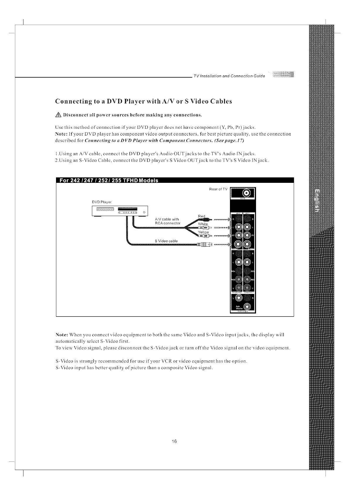
Connecting to aDVD Player with A/V or S Video Cables
Disconnect all power sources before making an)' connections.
Use this method of connection if your DVD player does not have component (Y, Pb, Pr) jacks.
Note: If your DVD player has component video output connectors, for best picture quality, use the connection
described for Connecting to a D VD Plarer with Component Connectors. (Seepage. 17)
1.Using an AiV cable, connect the DVD player's Audio OUT jacks to the TV's Audio IN jacks.
2.Using an S-Video (able, connect the DVD player's S Video OUT jack to the TV's S Video IN jack.
i_¥r_ l,ll,_[ _?. _-',l..-I,II,l.-f..-I I d" Iel _vi[;1_H _
RearofTV
DVD Player
I I
o
Red
A/V cable with
i _RCA connector White
S Video cable _ o
Note: When you connect video equipment to both the same Video and S-Video input jacks, the display will
automatically select S-Video first.
To view Video signal, please disconnect the S-Video jack or turn off the Video signal on the video equipment.
S-Video is strongly recommended for use if your VCR or video equipment has the option.
S-Video input has better quality of picture than a composite Video signal.
16
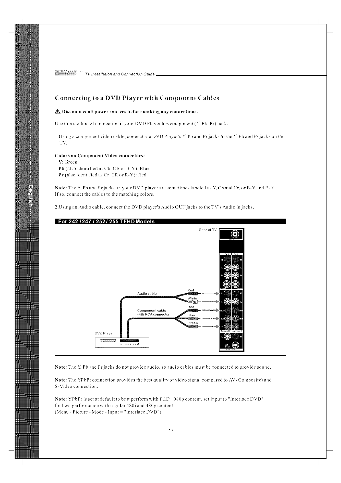
Connecting to a DVD Player with Component Cables
Disconnect all power sources before making any connections.
Use this method of connection if your DVD Player has component (Y, Pb, Pr) jacks.
1.Using a component video cable, connect the DVD Phlyer's Y, Pb and Prjacks to the Y, Pb and Prjacks on the
TV.
Colors on Component Video connectors:
Y: Green
Pb (also identified as Cb, CB or B-Y): Blue
Pr (also identified as Cr, CRor R-Y): Red
Note: The Y, 1 b and 1 r jacks on 3our DVD player are sometimes labeled as Y, Cb and Cr. or B-Y and R-Y.
If so, connect the cables to the matching colors.
2.U sing an Audio cable, connect the DVD player's Audio OUT jacks to the TV's Audio in jacks.
ia,Yr, l[l,l[I,,l[ _'_. _',g'l',lll,,l.l.ll II_l_II! ?__ fl _
Rear of TV
Red
Audio cable
DVD Player
I I
3 3
Note: The Y, 1 b and 1 r jacks do not provide audio, so audio cables must be connected to provide sound.
Note: The YPbPr connection provides the best qualityofvideo signal compared to AV(Composite) and
S-Video connection.
Note: YPbPr is set at default to best perform with FI1D 10S0p content, set Input to "hlterlace DVD"
for best performance w'ith regular 480i and 480p content.
(Menu-Picture-Mode-Input "InterlaceDVD")
17
TV Installation and Connection Guide
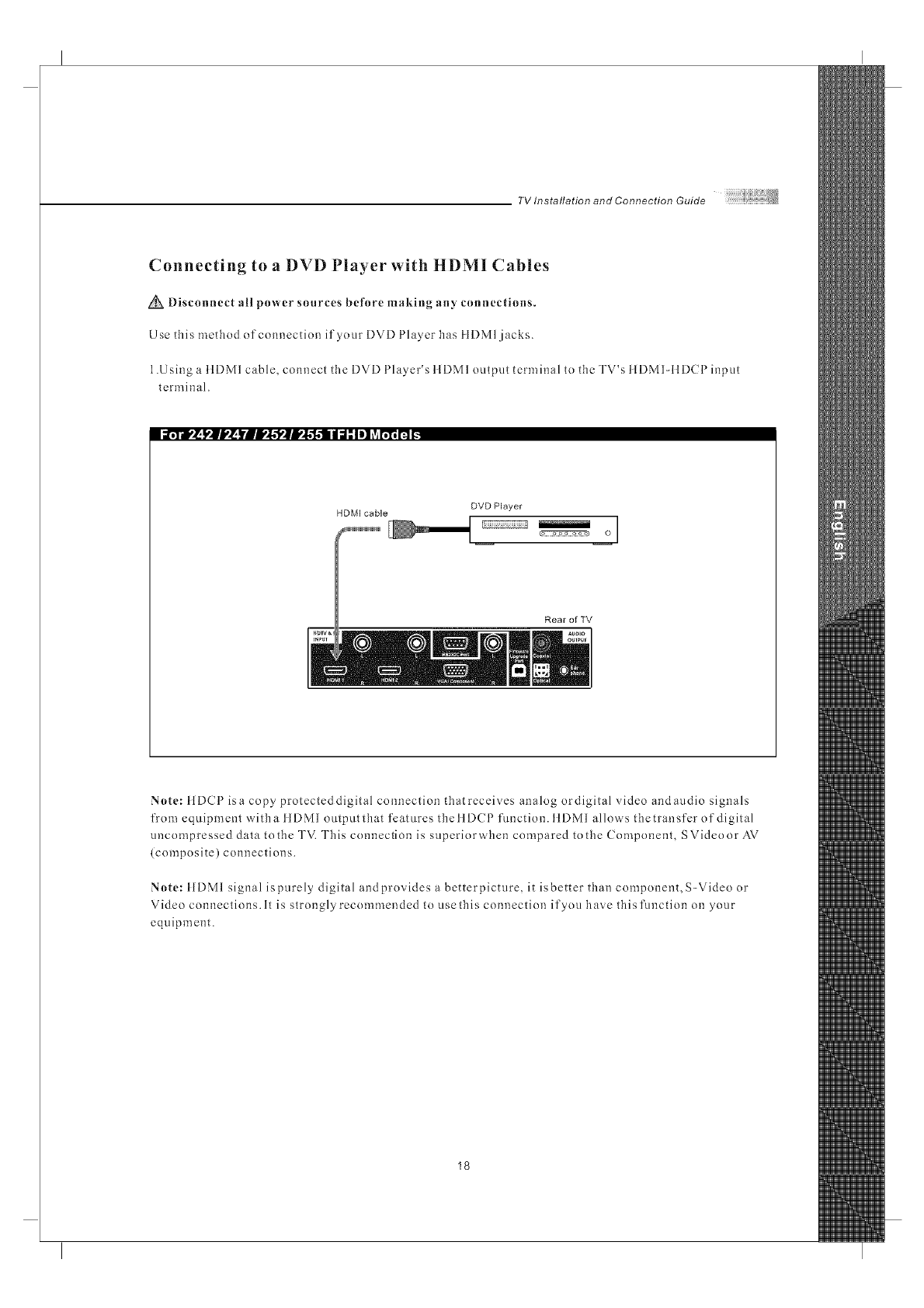
Connecting to a DVD Player with HDMI Cables
Disconnect all power sources before making any connections.
Use this method of connection if your DVD Player has IIDMI jacks.
1.Using a ItDMI cable, connect the DVD Player's ItDMI output terminal to the TV's IIDMI-IIDCP input
terminal.
i_.5--#,_ _'|J,_ Yill,,l.'l',ll,,l.l.li I J; Iel ?ir;T;_ _
DVD Player
HDM[ cable iiil o
i i
Rear of TV
Note: ttDCP isa copy protecteddigital connection thatreceives analog ordigital video andaudio signals
from equipment witha ttDMI outputthat features thettDCP function, ttDMl allows thetransfer of digital
uncompressed data to the TV. This connection is superiorwhen compared to the Component, SVideoor AV
(composite) connections.
Note: ItDM1 signal ispurely digital andprovides a betterpicture, it isbetter than component, S-Video or
Video connections. It is strongly recommended to use this connection if you have this function on your
equipment.
18
TVInstallationandConnectionGuide
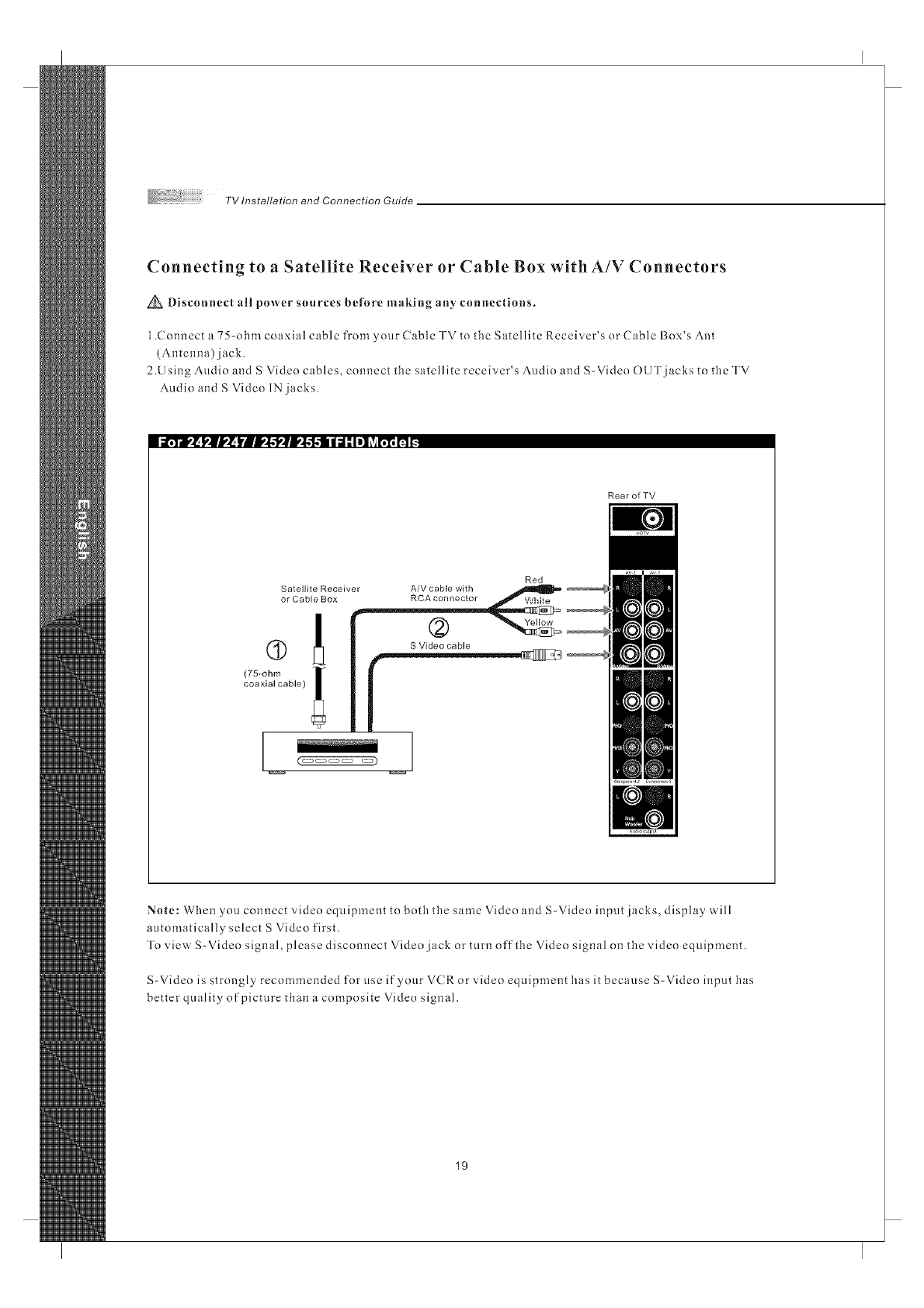
Connecting to a Satellite Receiver or Cable Box with A/V Connectors
_Disconnect all power sources before making any connections.
1.Connect a 75-ohm coaxial cable from your Cable TV to tile Satellite Receiver's or Cable Box's Ant
(Antenna) jack.
2.Using Audio and S Video cables, connect tile satellite receiver's Audio and S-Video OUT jacks to tile TV
Audio and S Video IN jacks.
li _,q--r,_ l,J[I,,_ I,II,,l,'l,_[I,,l,l,| | _l: II! ?__ m _
Rear of TV
Red
Satellite Receiver A/V cable with
or Cable Box RCA connector
Yellow
S Video cable
(75_ohm !
coaxial cable)
(_ _)
Note: When you connect video equipment to both the same Video and S-Video input jacks, display will
a_.ltomatically select S Video first.
To view S-Video signal, please disconnect Video jack or turn off the Video signal on the video equipment.
S-Video is strongly recommended for use if your V(Ror video equipment has it because S-Video input has
better quality of picture than a composite Video signal.
19
TV Installation and Connection Guide
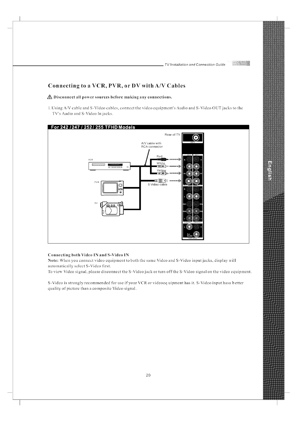
Connecting to aVCR, PVR, or DV with A/V Cables
Disconnect nil power sources before making any connections.
1.Using AiV cable and S-Video cables, connect the video equipment's Audio and S-Video OUT jacks to the
TV's Audio and S-Video In jacks.
li _¥1'_ !'|i,'_ YBIP_'l'alP_'f,,'li I d" Io] ?Ar;_ n _.
VCR
oI
Rear of TV
A/V cable with
RCA connector
S Video cable
Connecting both Video IN and S-Video IN
Note: When you connect video equipment to both the same Video and S-Video input jacks, display will
automatically select S-Video first.
To view Video signal, please disconnect the S-Video jack or turn off the S-Video signal on the video equipment.
S-Video is strongly recommended for use if your V(R or videoeq uipment has it. S-Video input hasa better
quality of picture than a composite Video signal.
2O
TVlnstallationandConnectionGuide
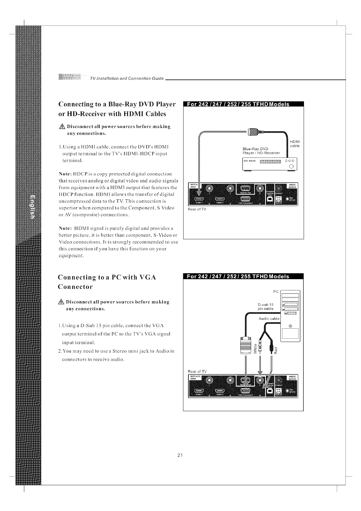
Connecting to a Blue-Ray DVD Player
or HD-Receiver with HDMI Cables
Discouuect all power sources before making
any connections.
1.Using a ItDMI cable, connect the DVD's ItDMI
output terminal to the TV's llDMl-llDCPinput
terminal.
Note: HDCPis a copy protected digital connection
that receives analog or digital video and audio signals
from equipment with a ttDMI output that features the
ttDCP function, ttDM1 allows the transfer of digital
uncompressed data to the TV. This connection is
superior when compared to the Component, S Video
or AV (composite) connections.
Note: ttDMI signal is purely digital and provides a
better picture, it is better than component, S-Video or
Video connections. It is strongly recommended to use
this connection if you have this function on your
equipment.
i_dV_ I1 rJ,,_k'i rll,,l,l,'llll,,l,-1,111di l Iel _viI1'I1_ _.
Connecting to a PC with VGA
Connector
Disconnect all power sources before maMug
an)' counectious.
1.Using a D-Sub 15 pin cable, connect the VGA
output terminal of the PC to the TV's VGA signal
input terminal.
2.You may need to use a Stereo mini jack to Audio in
connectors to receive audio.
Rear of TV
Rear of TV
PC--
D-sub 15
pin cable _
@
@
21
TV Installation and Connection Guide
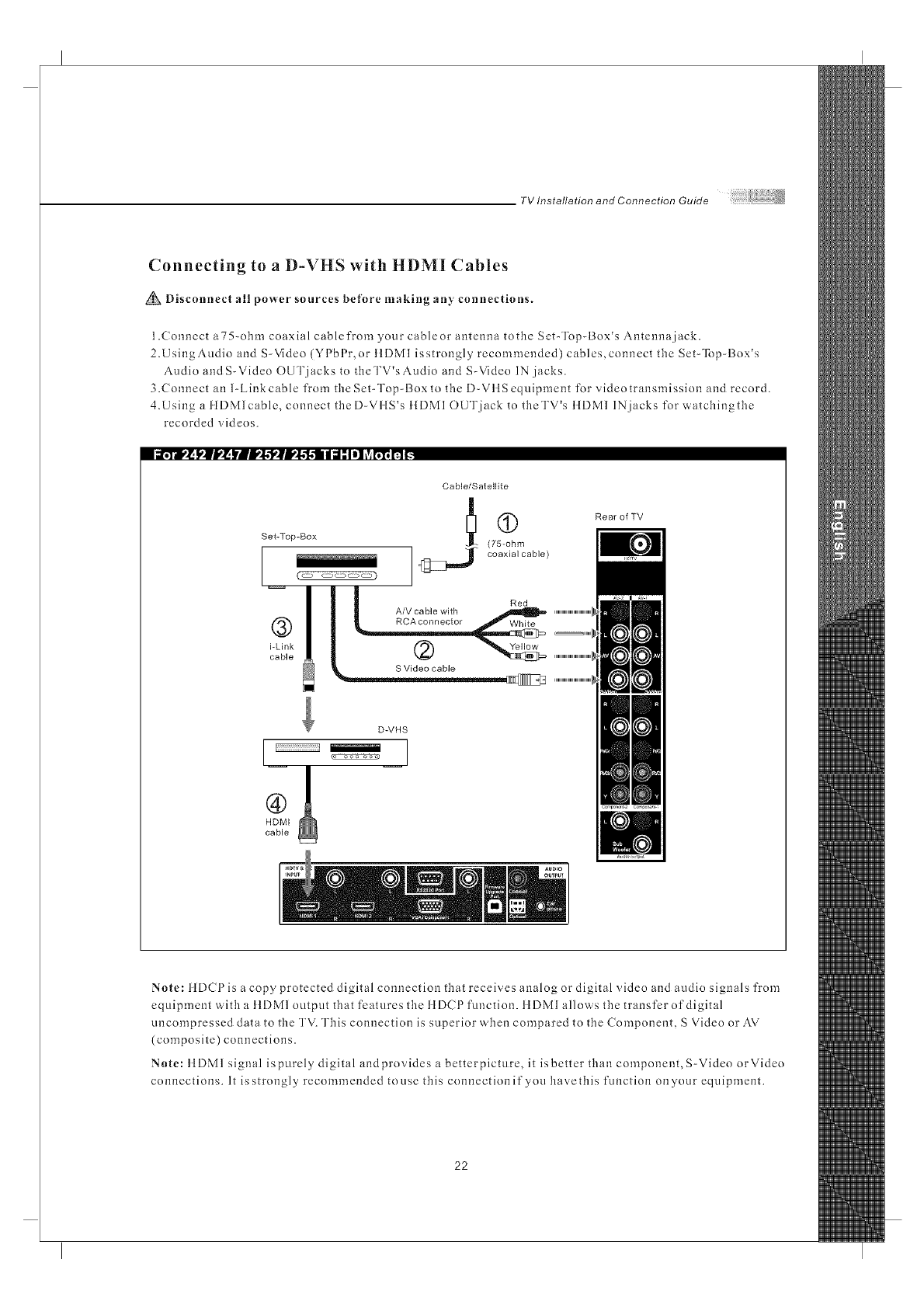
Connecting to aD-VHS with HDMJ Cables
Disconnect all power sources before making any connections.
1.Connect a75-obm coaxial cablefrom your cablcor antenna totbe Set-Top-Box's Antenna jack.
2.UsingAudio and S-Video (YPbPr, or ttDMI isstrongly recommended) cables,connect the Set-Top-Box's
Audio andS-Video OUTjacks to theTV's Audio and S-Video IN jacks.
3.Connect an 1-Link cable from the Set-Top-Box to tbc D-VttSequipment for video transmission and record.
4.Using a }tDMlcable, connect tbeD-VilS's }tDMI OUT jack to theTV's }IDMI IN jacks for watchingthc
recorded videos.
i_.To',_ _'|J,'_ )'Afli,_.?ali,_."l.ll d;i ."I el ?_l';'l'_I'__.
Set-Top-Box
!
®
i-Link
cable
Cable/Satelllte
(75-ohm
_j_" coaxial cable)
Red
A/V cable with
RCA connector White
Rear of YV
D-VHS
I' I
HDMI
cable
Note: ttDCPis a copy protected digital connection tbat receives analog or digital video and audio signals from
equipment with a ttDM1 output that features tbc ttDCP function, ttDMI allows tbe transfer of digital
uncompressed data to tbe TV. This connection is superior when compared to the Component, S Video or AV
(composite) connections.
Note: ttDMI signal ispurely digital andprovides a betterpicture, it isbetter than component, S-Video orVideo
connections. It is strongly recommended to use this connection if you bavethis function on your equipment.
22
TV Installation and Connection Guide
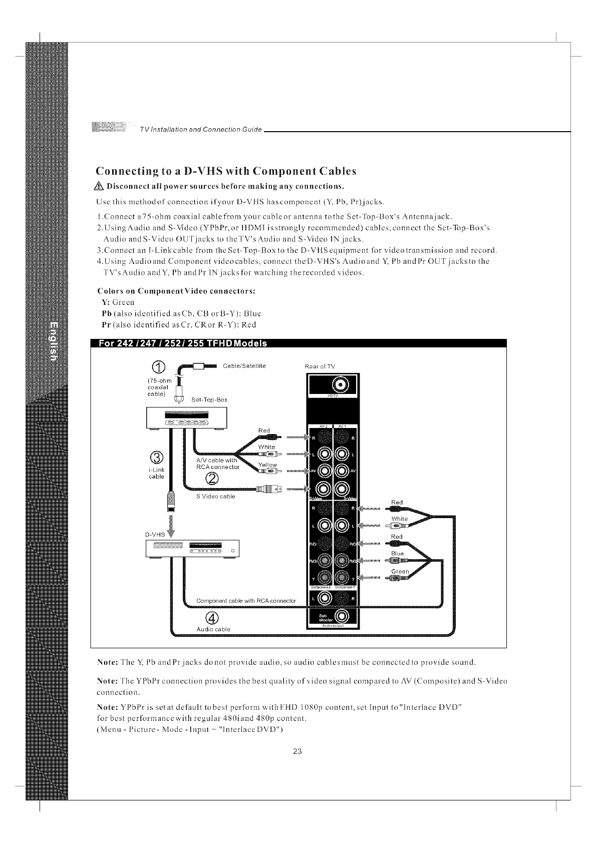
Connecting to a D-VHS with Component Cables
Disconnect all power sources before nlaking any connections.
Use this methodof connection if your D-VflS hascomponent (Y, Pb, Pr)jacks.
1.Connect a75-ohm coaxial cablefrom your cableor antenna tothe Set-Top-Box's Antenna jack.
2.UsingAudio and S-Video (YPbPr, or ttDMI isstrongly recommended) cables,connect the Set-Top-Box's
Audio andS-Video OUT jacks to theTV's Audio and S-Video IN jacks.
3.Connect an I-Linkcable from the Set-Top-Box to the D-VttSequipment for video transmission and record.
4.Using Audioand Component videocables, connect theD-VttS's Audioand Y. Pb andPr OUTjacksto the
TV'sAudio andY, Pb andPr IN jacks for watching therecorded videos.
Colors on ComponentVideo connectors:
Y: Green
Pb (also identified asCb, CB orB-Y): Blue
Pr (also identified asCr, CRor R-Y): Red
._lllllI_]lllll_ Cable/Satelllte
(75-ohm ][
sot-Top-Box
l-- Red
®
i-Link
cable
B Video cable
RearofTV
Red
Red
®
Audio cable
Note: The Y, Pb and Pr jacks do not provide audio, so audio cables must be connected to provide sound.
Note: The YI bl r connection provides the best quality of video signal compared to AV (Composite) and S-Video
connection.
Note: YPbPr is setat default to best perform with HiD 1080p content, set Input to"lnterlace DVD"
for best performancew'ith regular 480land 480p content.
(Menu-Picture-Mode-Input "InterlaceDVD")
23
TV Installation and Connection Guide
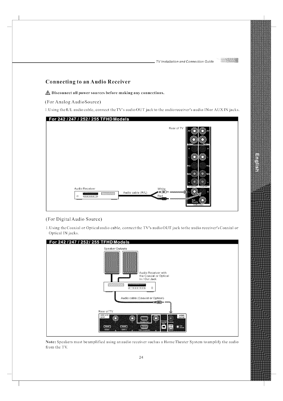
Connecting to an Audio Receiver
Disconnect all power sources before making an)' connections.
(For Analog AudioSource)
1.Using theRiL audio cable, connect tbeTV's audio OUT jack to the audio receiver's audio IN or AUXIN jacks.
Rear of TV
Audlo Receiver White
I_IAudi° cable (R/L)
o _ I
(For Digital Audio Source)
1.Using theCoaxial or Optical audio cable, connectthe TV's audioOUT jack tothe audio receiver'sCoaxial or
Optical IN jacks.
Speaker Outputs
Audio Receiver with
the Coaxial or Optical
In /Out Jack
O
Audio cable (Coaxial or Optical)
Rear of TV
Note: Speakers must beamplified clsing anaudio receiver suchas a llomeTheater System to)amplify tbe audio
from tbe TV.
24
TV Installation and Connection Guide
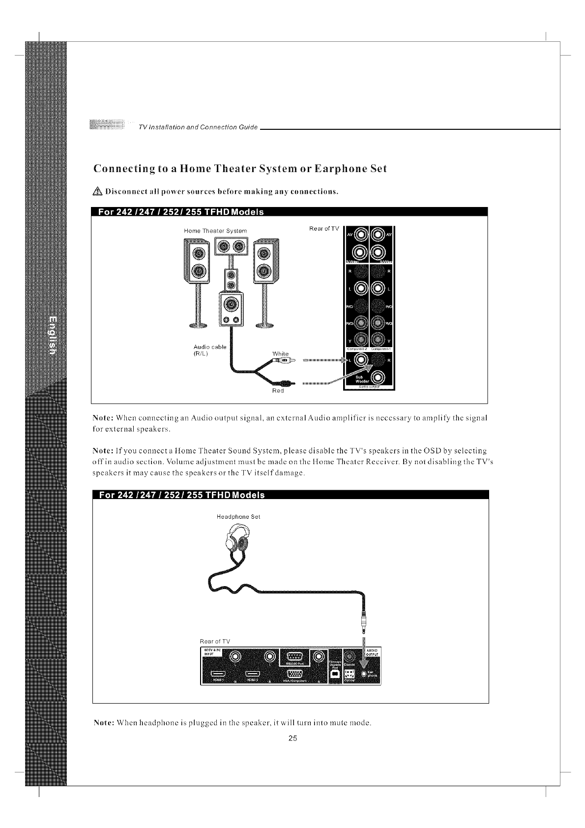
Connecting to a Home Theater System or Earphone Set
Disconnect all power sources before making any connections.
i_.7_dr'__.mb,_ lrBW$_lW$-f..-tll d;I ,"Iel _v_L";_n _
Home Theater System Rear of TV
Audio cable
(R/L) White
Red
Note: When connecting an Audio nutput signal, an external Audio amplifier is necessary to amplify the signal
for external speakers.
Note: If you connect a ltome Theater Sound System, please disable the TV's speakers in the OSD by selecting
off in audio section. Volume adjustment must be made on the llnme Theater Receiver. By not disabling the TV's
speakers it may cause the speakers or the TV itself damage.
i_¥dt,_ I,|V_ lrlli,$'k'lli,$'f.ll d;I _Iel _vil';l_[a _.
Headphone Set
a
Rear of TV
Note: When headphone is plugged in the speaker, it ,,','ill turn into mute mode.
25
TV Installation and Connection Guide
Instruction for Uploading New Firmware
1.(]o to our website : www.o levia.com and register your "]'VI
2.Clickl'uturelroot yourTV. Y0uwillneedtheserialnumberofyourOleviaTVanda USBflashdrive.
3.Click on the instructions for your particular model of Olevia TVI
26
,mote Control Guide
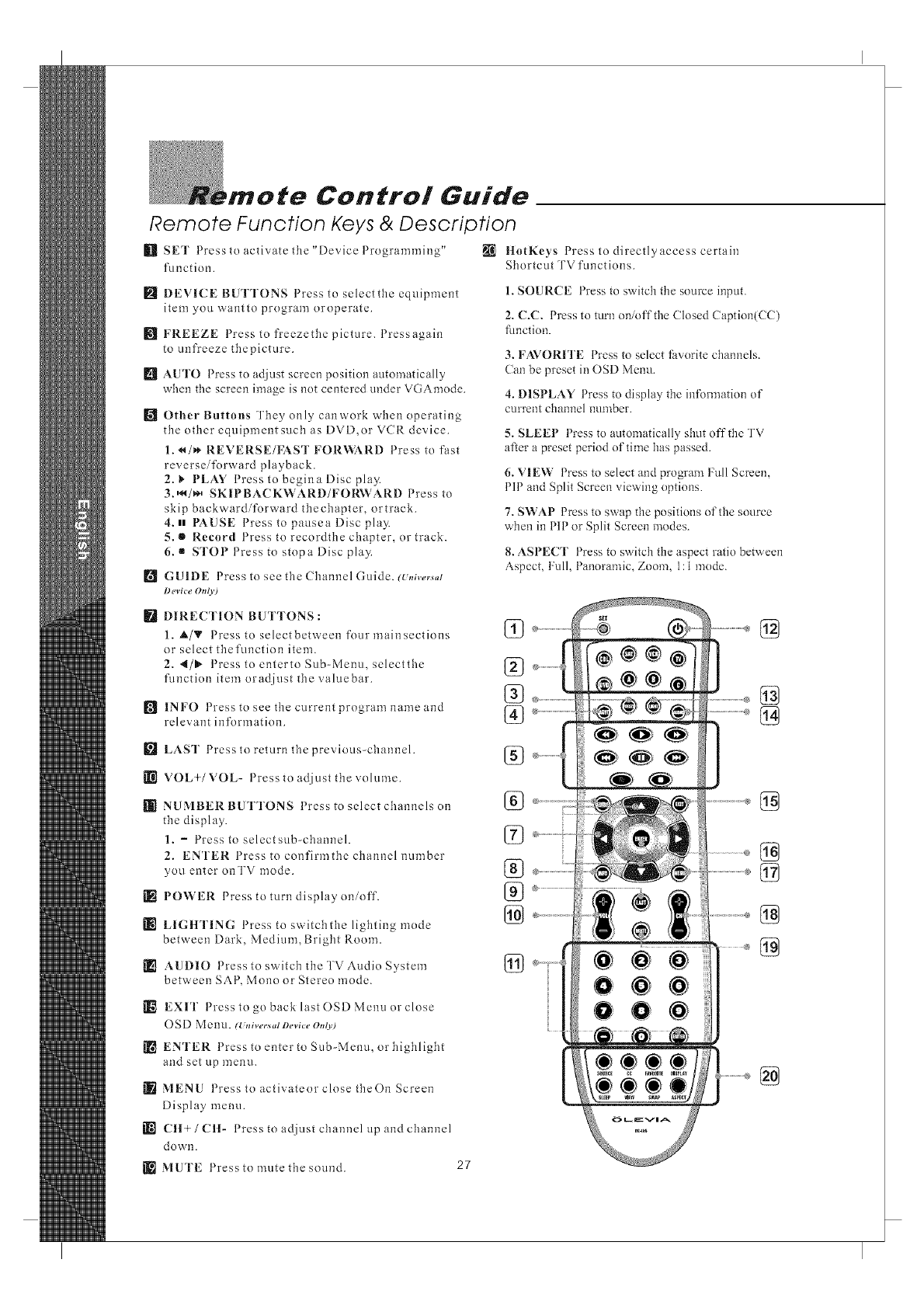
Remote Function Keys & Description
_]] SET Press to activate the "DevicePrngranm]ing" _ ltotKeys Press to directly access certain
function. Shortcut TV functions.
_l DEVICE BUTTONS Press to selectthe equipment
item you wantto program oroperatc.
[] FREEZE Press to freezethc picture. Pressagain
to unfreeze thepicmre.
[] AUTO Press to adjust screen position automatically
when the screen image is not centered under VGAmode.
[] Other Buttons They only canwork when operating
the other equipment such as DVD,or VCR device.
1. _/_* REVERSE/FAST FOR_,}_RD Press to fast
reversei%rward playback.
2. _ PLAY Press to begina Disc play.
3.,_/_,, SKII:'BACKWARD/FORWARD Press to
skip backward/forward thechapter, ortrack.
4. H PAUSE Press to pausea Disc play.
5. • Record Press to recordthe chapter, or track.
6. •STOP Press to stopa Disc pla3_
[] GUIDE Press to see the Channel Guide. (U,,iversal
Device Ot_ly)
[] DIRECTION BUTTONS :
1. _,/_' Press toselectbetween fourmainsections
or select thefunction item.
2. 4/1_ Press toentertoSub-Menu, selectthc
function item oradjust the valuebar.
[] INFO 1 ress to see the current program name and
relevant information.
[] LAST Press to return the previous-channel.
VOL+/VOL- Press to adjust the volume.
[]_ NUMBER BUTTONS Press to select channels on
the display.
1. -Press to selectsub-channel.
2. ENTER Press to confirmthe channel number
you enter onTV mode.
[R POWER Press to turn display on/off.
LIGItTING Press to switchthe lighting mode
between Dark, Medium, Bright Room.
[] AUDIO Press to switch the TV Audio System
between SAP, Mono or Stereo mode.
[]_ EXIT Press to go back last OSD Menu or close
O SD Menu. (Univecs,d Device OnO0
[] ENTER Press to enter to Sub-Menu, or highlight
and set up menu.
MENU Press toactivateorclosetheOn Screen
Display menu.
[[_'1 Ctt+/CH- Press to adjust channel up and channel
down.
MUTE Press to mute the sound. 27
1. SOURCE Press to switch the snurce input.
2. C.C. Press to turn oninffthe (losed (aption(CC)
fimction.
3. FAVORITE Press to select favorite channels.
Can be preset in OSD Menu.
4. DISPLAY Press to display the infom]ation of
current channel number.
)/
5. SLEEP 1 tess to automaticall 3 shut offthe TV
after a preset period nf time has passed.
6. VIEW Press to select and program Full Screen,
PIP and Split Screen viewing options.
7. SWAP Press to swap the positions of the source
when in PIP or Split Screen modes.
8. ASPECT Press to switch the aspect ratio between
Aspect, Full, Panoramic, Zoom, 1:1 mode.
%
%
%
%
%
%
%
%
@
@
Remote Control Guide
Programming the Remote Control
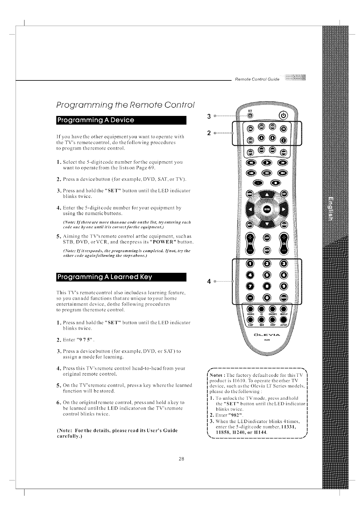
If you have the other equipment you want to operate with
the TV's remotecontrol, do thefolh)wing procedures
to program theremote control.
1. Select the 5-digitcode number forthe equipment you
want to operatefrom the listson Page 69.
2. Press a devicebutton (for example, DVD, SAT, or TV).
3. Press and hold the "SET" button until the LED indicator
blinks twice.
4. Enter the 5-digitcode number foryour equipment by
using the numericbuttons.
6_'ote: lf therem+e more thorn one code on the list, to, enteriit _, each
code oste b.vot_e ut_til iris corl+ect.[brthe equipmestt.)
5. Aiming the TV'sremote control atthe equipment, such as
STI3, DVD, orVCR, and thenpress its "POWER" button.
(No re: I['it resp o n ds, th e p rogra m m ing is co mp leted, lj'#t ot, t O, th e
other code aL_ai#+/bllowinL_ the _t_,p_abov_,.)
This TV's remotecontrol also includesa learning fcature,
so you canadd functions that are unique toyour home
entertainment device, dothe following procedures
to program theremote control.
1. Press and hold the "SET" button until the LED indicator
blinks twice.
2. Enter "9 7 5".
3. Press a devicebutton (for example, DVD, or SAT) to
assign a mode for learning.
4. Press this TV'sremote control head+to+head from your
original remote control.
5. On the TV'sremote control, pressa key wherethe learned
function will be stored.
6. On the original remote control, press and hold akey to
be learned untilthe LED indicatoron the TV'sremote
control blinks twice.
(Ntlte: For the details, please read its User's Guide
carefully.)
3
2
Notes :The t?ictory det?iuhcode for thisTV I
product is 11610. To operate theother TV _1
device, such asthe Ole'via LT Series models, i
please do the following :
|. To unlock the TVmode, press and hold
the "SET" button until theLED indicator
blinks twice.
2, Enter "982".
3. When the LEDindicator blinks 4times,
enter the 5-digitcode number, 1133L
11858, 11240, or 11144.
28
RemoteControlGuide
Battery Installation
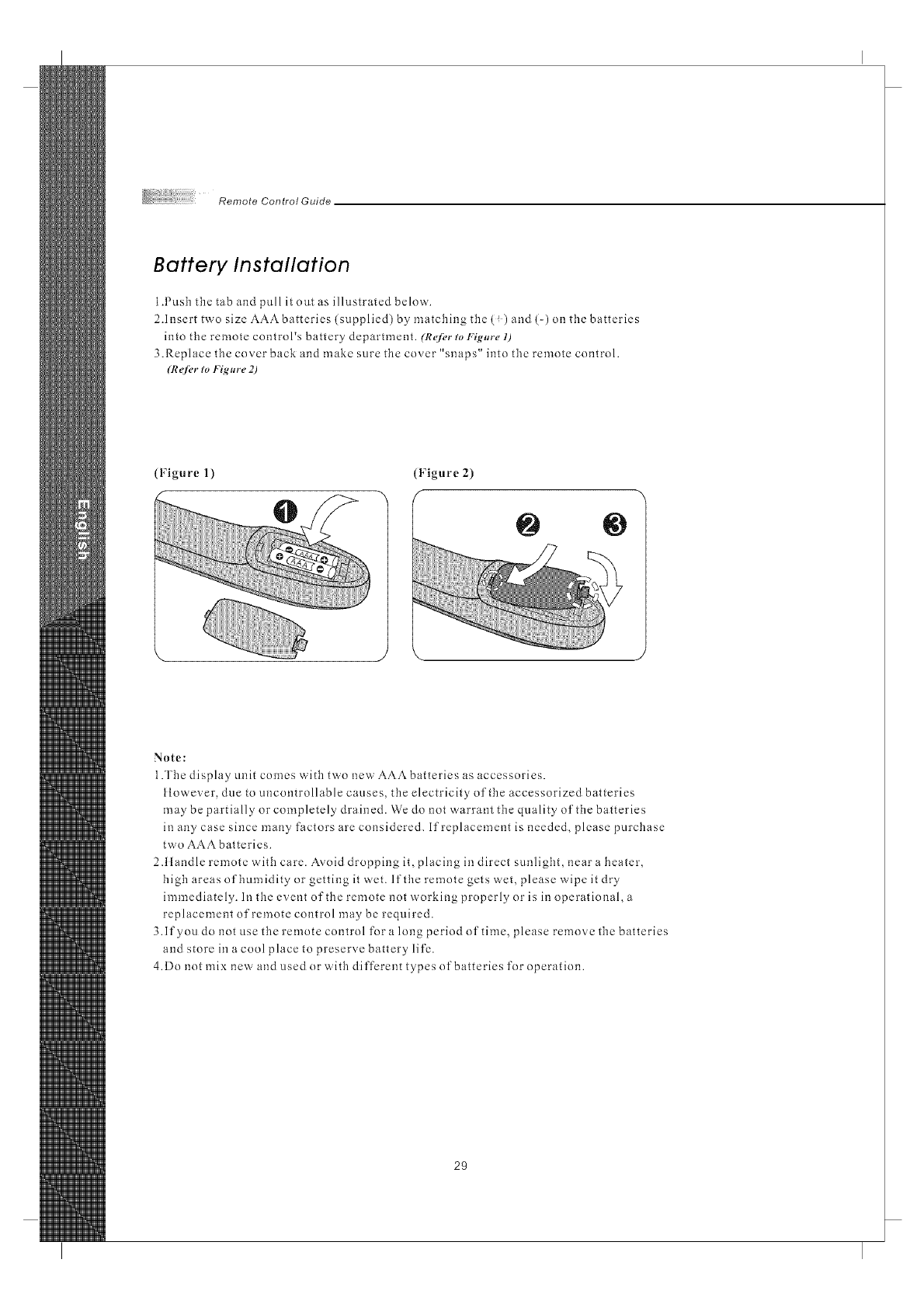
1.Pusb tbe tab and pull it out as illustrated below.
2.Insert two size AAAbatteries (supplied) by matching the (!) and (-) on tbe batteries
into the remote control's battery department. (R_/_,r to Yig,r_, 1)
3.Replace the cover back and make sure the cover "snaps" into tbe remote control.
(R_fi, r to Figm_e 2)
(Figure 1) (Figure 2)
@
Note:
1.The display unit comes with two new AAAbatteries as accessories.
tlowever, due to uncontrollable causes, the electricity oftbe accessorized batteries
may be partially or completely drained. We do not warrant the quality of the batteries
in any case since many factors are considered. If replacement is needed, please purcbase
two AAA batteries.
2Alandle remote with care. Ax.oid dropping it, placing in direct sunlight, near a beater,
high areas of bumidity or getting it wet. If the remote gets wet, please wipe it dry
immediately. In tbe event oftbe remote not working properly or is in operational,a
replacement of remote control may be required.
3.If you do not use the remote control for a long period of time, please remove tbe batteries
and store in a cool place to preserve battery life.
4.Do not mix new and used or with different types of batteries for operation.
29
Screen Displays (OSD),
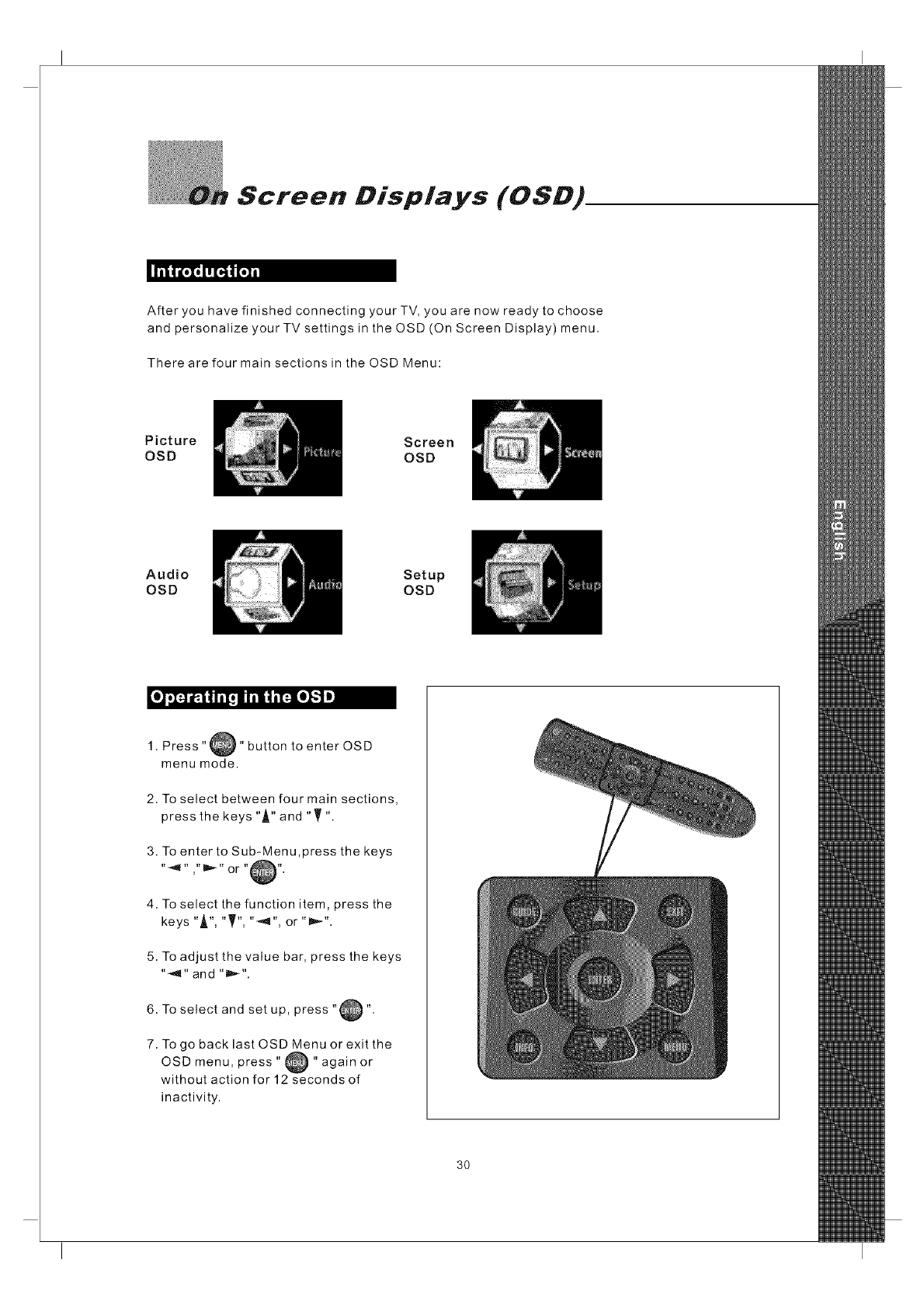
After you have finished connecting your TV, you are now ready to choose
and personalize your TV settings in the OSD (On Screen Display) menu.
There are four main sections in the OSD Menu:
Picture
OSD Screen
OSD
Audio
OSD Setup
OSO
1. Press"_" button to enter OSD
menu mode.
2. To select between four main sections,
press the keys "A" and "T"
3. To enter to Sub-Menu ,press the keys
4. To select the function item, press the
keys "A", "T", "_'q", or "lm,_".
5. To adjust the value bar, press the keys
"_" and "D,,-".
6. To select and setup, press "@".
7. To go back last OSD Menu or exit the
menu, press " _ " again or
OSD
without action for 12 seconds of
inactivity.
3O
OnScreenDisplays(OSD)
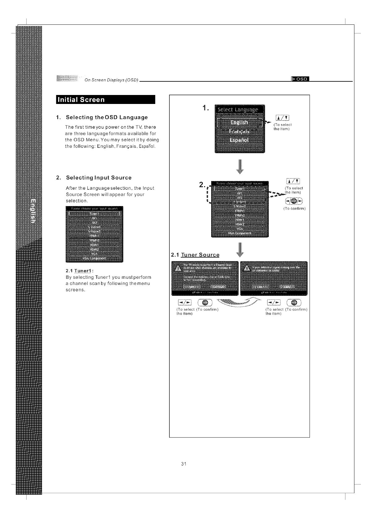
1. Selecting theOSD Language
The first timeyou power onthe TV, there
are three languageformats available for
the OSD Menu.You may select itby doing
the following: English, Franqais, EspaS"ol.
2. Selectingtnput Source
After the Languageselection, the Input
Source Screen will appear for your
selection.
2.1 Tuner1:
By selecting Tuner1 you must perform
a channel scan by following the menu
screens.
,
2.1 Tuner Source
(To select
the item)
_._..L.v]
(To select
(To confirm)
(To select (To confirm) (To select (To confirm)
the item) the item)
31
On Scree n Displays (0 SD)
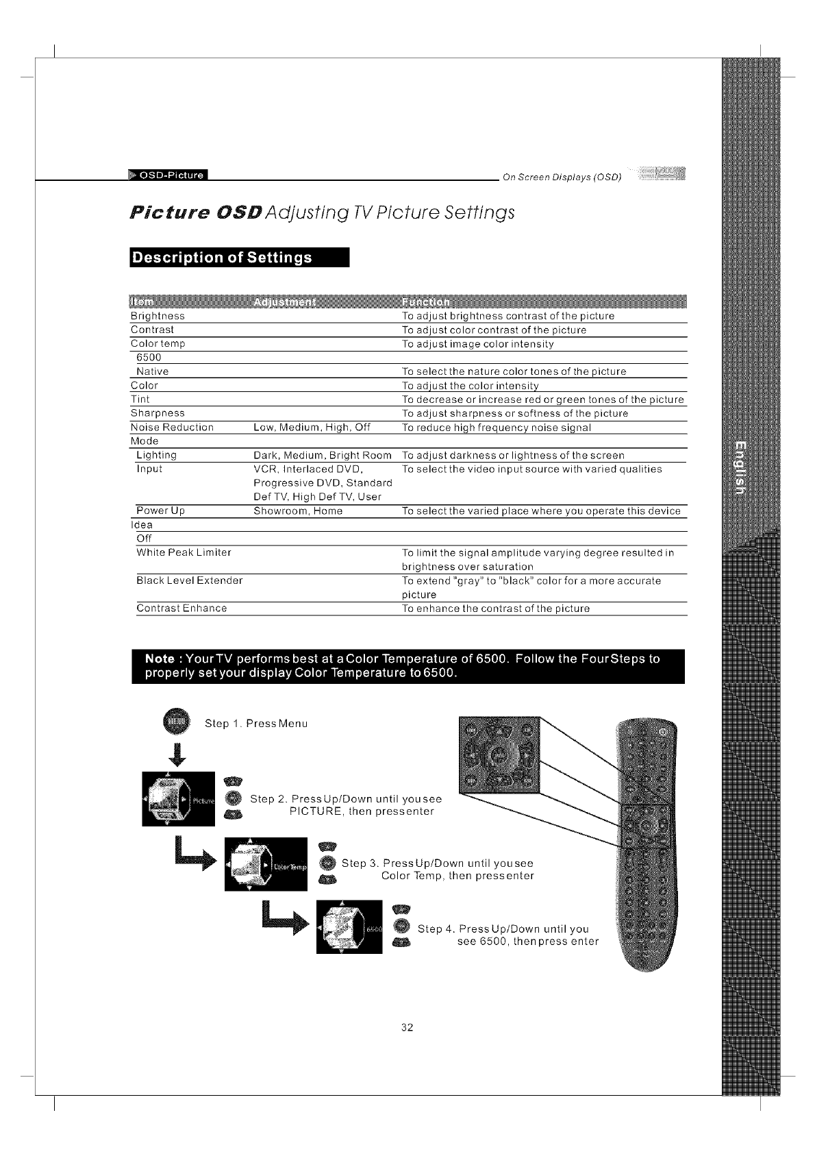
Picture OSD Adjusting TV Picture Settings
Brightness To adjust brightness contrast of the picture
Contrast
Color temp
6500
Native To select the nature color tones of the picture
Color To adjust the color intensity
Tint To decrease or increase red or green tones of the picture
Sharpness To adjust sharpness or softness of the picture
Noise Reduction Low, Medium, High, Off To reduce high frequency noise signal
Mode
Lighting Dark, Medium, Bright Room To adjust darkness or lightness of the screen
Input VCR, Interlaced DVD, To select the video input source with varied qualities
Progressive DVD, Standard
Def TV, High Def TV, User
Power Up Showroom, Home To select the varied place where you operate this device
Idea
Off
White Peak Limiter To limit the signal amplitude varying degree resulted in
brightness over saturation
Black Level Extender To extend "gray" to "black" color for a more accurate
picture
Contrast Enhance To enhance the contrast of the picture
To adjust color contrast of the picture
To adjust image color intensity
$
Step 1. PressMenu
O Step 2. PressUp/Down until yousee
O PICTURE, then pressenter
O Step3. PressUp/Down untilyousee
Color Temp, then pressenter
Step 4. PressUp/Down until you
see 6500, then press enter
32
On Screen Displays (OSD)
,'I'_!r4rll i iil! i i iTtl lilil iii il-.ll iraIiII 1:
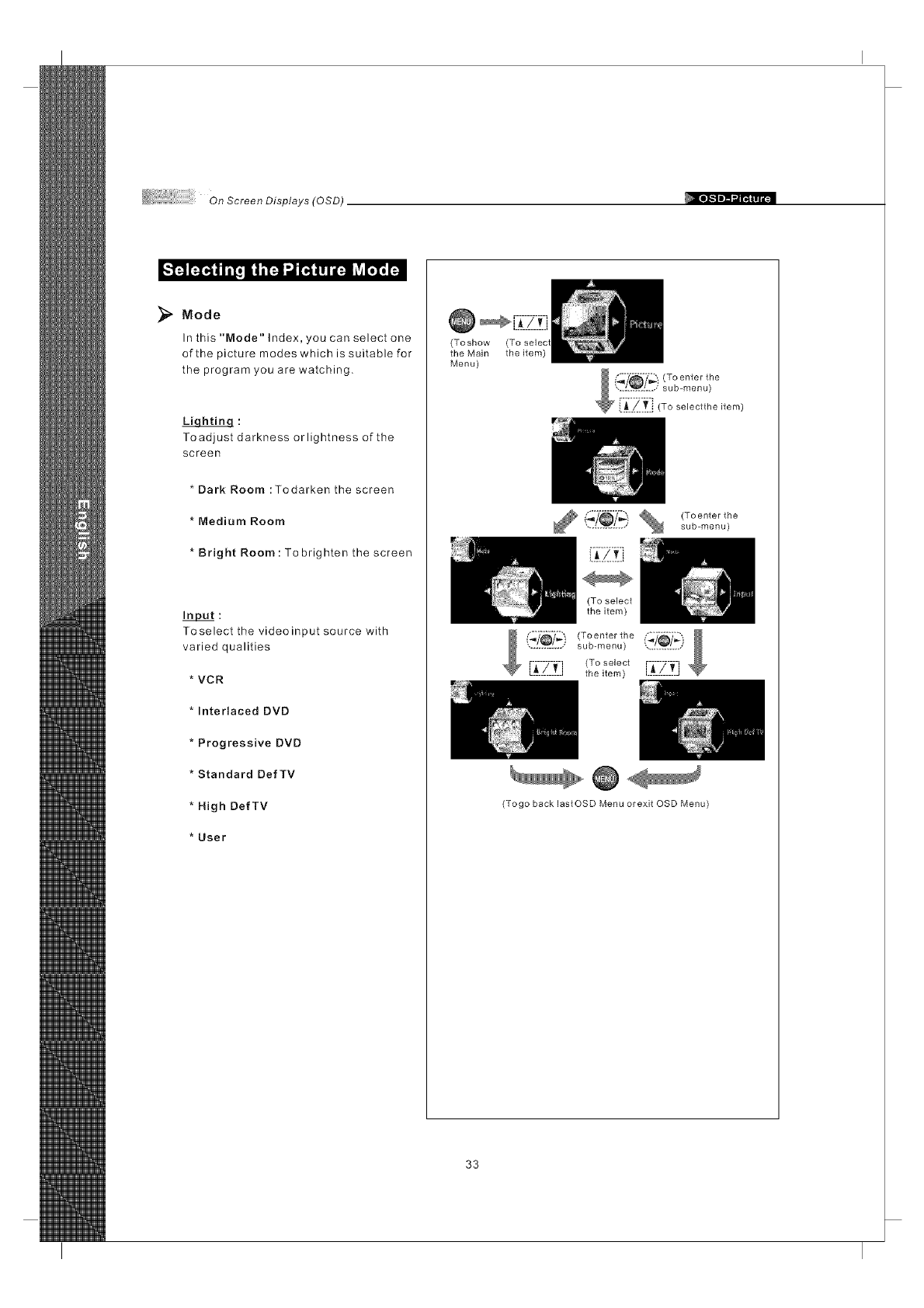
Mode
In this "Mode" Index, you can select one
of the picture modes which is suitable for
the program you are watching.
Toadjust darkness orlightness of the
screen
* Dark Room :Todarken the screen
* Medium Room
* Bright Room: To brighten the screen
Input:
Toselect the videoinput source with
varied qualities
VCR
Interlaced DVD
Progressive DVD
Standard DefTV
High DefTV
User
_[7_-7__-_-f;J
(Toshow
the Main the item)
Menu)
(Toenter the
sub-menu)
(To select
the item)
.............. sub-menu)
.............<To_o,oo,r-i-7-l-i
Lt!__Li thei_em/ .............
(Togo back lastOSD Menu orexit OSD Menu)
33
On Screen Displays (OSD)
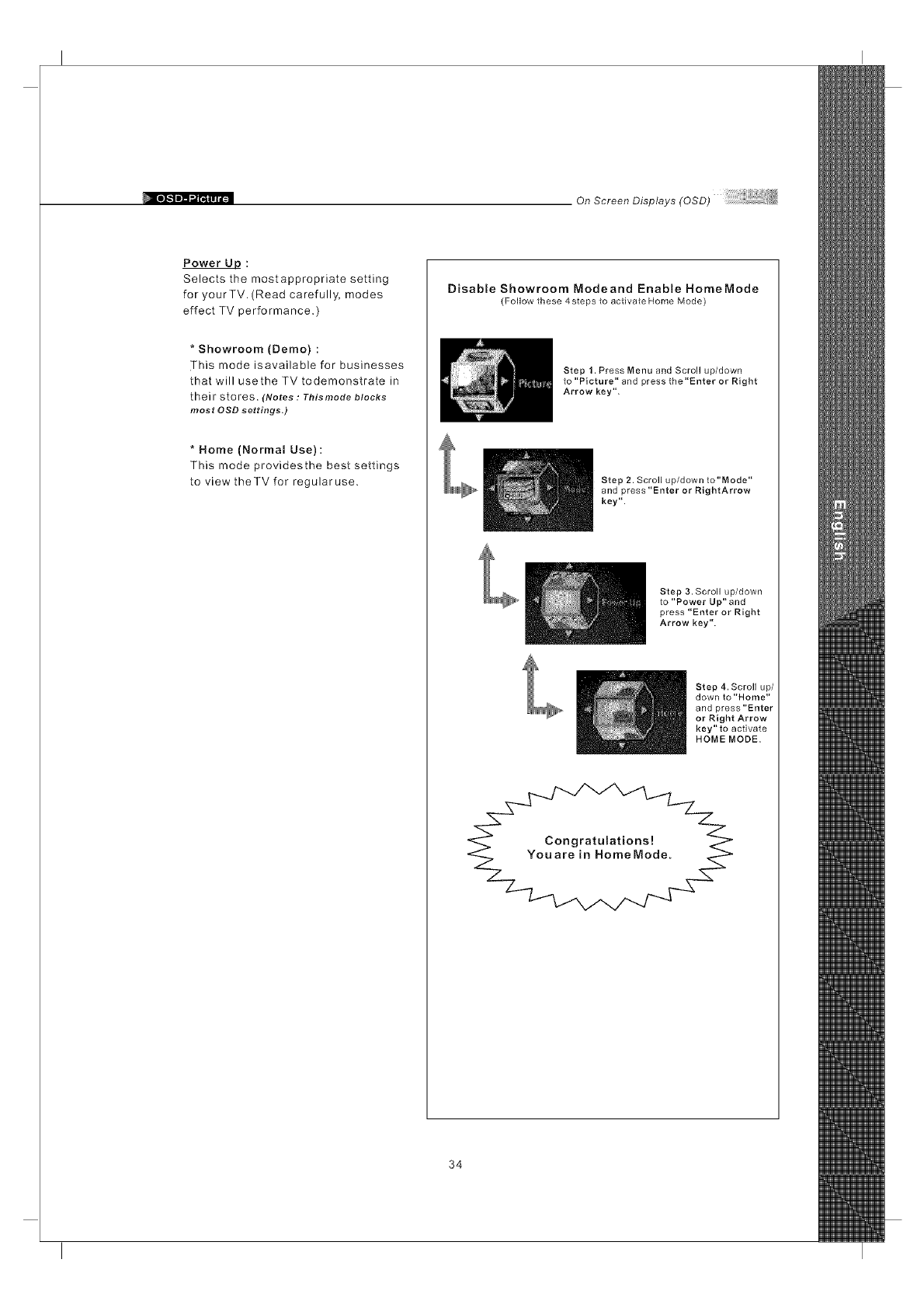
Power LID :
Selects the mostappropriate setting
for yourTV. (Read carefully, modes
effect TV performance.
*Showroom (Demo)
This mode isavailable for businesses
that will usethe TV todemonstrate in
their stores. (Notes : Tbismode blocks
most OSD settings.)
* Home (Normal Use) :
This mode providesthe best settings
to view theTV for regularuse.
Disable Showroom Modeand Enable HomeMode
(Follow these 4 steps to activate Home Mode)
Step 1. Press Menu and Scroll up/down
to "Picture" and press the"Enter or Right
Arrow key".
Step 2. Scroll up/down to"Mode"
and press "Enter or RightArrow
key".
Step 3. Scroll up/down
to "Power Up" and
press "Enter or Right
Arrow key".
Step 4. Scroll up/
down to "Home"
and press "Enter
or Right Arrow
key" to activate
HOME MODE.
34
OnScreenDisplays(OSD)
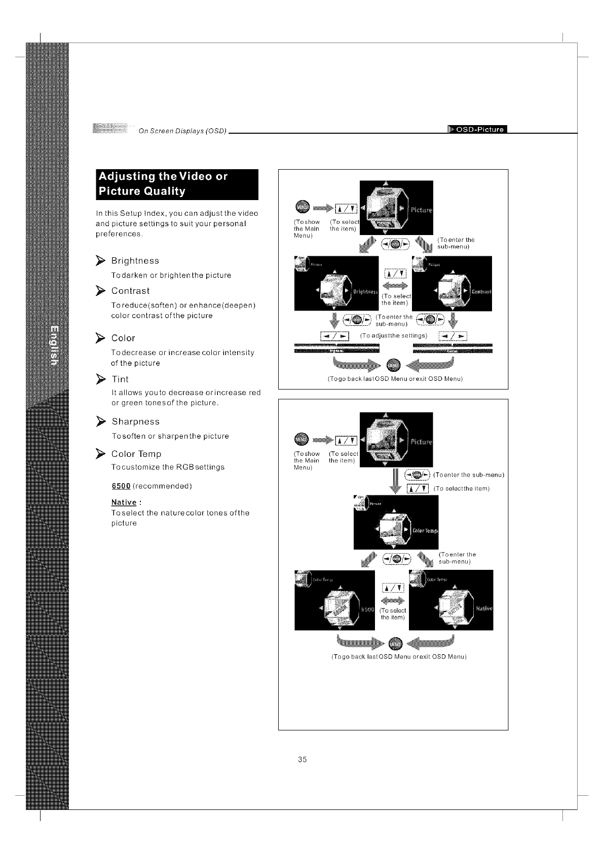
In this Setup Index, you can adjust the video
and picture settings to suit your personal
preferences.
}_ Brightness
Todarken or brightenthe picture
_ Contrast
To reduce(soften) or enhance(deepen)
color contrast of the picture
_, Color
Todecrease or increase color intensity
of the picture
}_. Tint
It allows youto decrease orincrease red
or green tonesof the picture.
_ Sharpness
Tosoften or sharpenthe picture
Color Temp
Tocustomize the RGBsettings
6500 (recommended)
Native :
Toselect the naturecolor tones ofthe
picture
(Toshow
the Main the item)
Menu)
(_'_) _ (To enter the
.............. sub-menu)
[',-._--::Z---_ :l (To adjustthe settings)i._[[_: "_:j
@
(Togo back lastOSD Menu orexit OSD Menu)
(Toshow (To select
the Main the item)
Menu)
_:_!__.[_) (Toenter the sub ..... )
i___._/_£.i(Toselecttheitem)
(_'_'_'_'_ _ (To enterthe.............. sub-menu)
(Togo back lastOSD Menu orexit OSD Menu)
35
On Screen Displays (OSD)
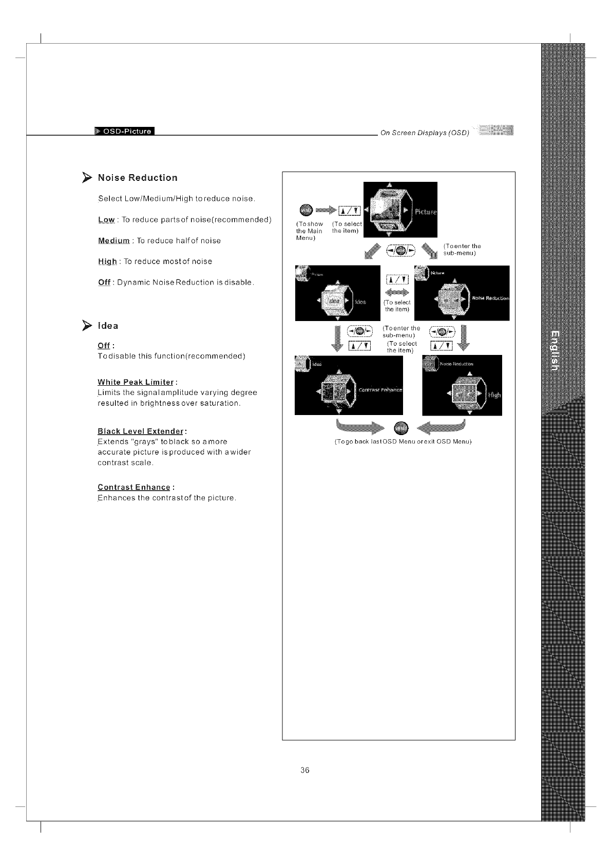
Noise Reduction
Select Low/Medium/High to reduce noise.
: To reduce partsof noise(recommended)
Medium : To reduce halfof noise
H!gh : To reduce mostof noise
Off : Dynamic Noise Reduction is disable.
idea
Off :
Todisable this function(recommended)
White Peak Limiter:
Limits the signalamplitude varying degree
resulted in brightnessover saturation.
Black Level Extender:
Extends "grays" to black so amore
accurate picture is produced with awider
contrast scale.
Contrast Enhance:
Enhances the contrastof the picture.
(To show
the Main
Menu)
(To select
the item)
............... sub-menu)
i_/_7_ ) (Toenter the
................ b ..... ) ___!_7._)
[-_-i-_j (To select E_[Zlt"
........... the item)
(Togo back lastOSD Menu orexit OSD Menu)
36
On Screen Displays (OSD)
Audio OSD Adjusting Sound Quality
Treble It allows to adjust higher pitched sounds.
Bass It allows to adjust lower pitched sounds.
Balance It allows to adjust volume balance of the R/Lspeakers for
the best stereo reproduction.
Language English, Frangais, EspaBol There are three language formats available for program
broadcasting.
MTS(Multi-channe/ Mono, SAP, Stereo It allows to select the sound reception of stereo, bilingual
Television Sound) and mono programs between the TV Audio System.
Mute On, Off It allows to mute the sound.
Speaker On, Off It allows to turn On/Offthespeakers of the TVwhen using
a Receiver or Home Theater System.
iDIVA Off, Rock, POP, Live, Classic, It allows to select the sound effect as occurred in an
Soft, Concert, Living Room, enclosed space of varying spaces.
Hall, Arena, Church
Lip Sync It allows to properly synchronize the audio and video.
;T;__i_ t Ii[! i|iT'-I;TI'_ lr;l.',_J | _ii[i i
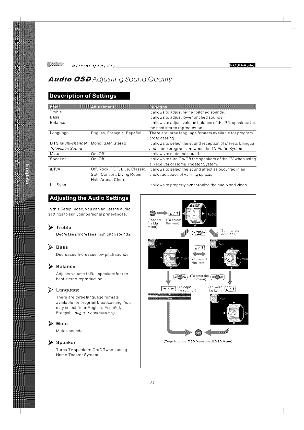
In this Setup Index, you can adjust the audio
settings to suit your personal preferences.
Treble
Decreases/Increases high pitchsounds.
Bass
Decreases/Increases low pitchsounds.
_" Balance
Adjusts volume toR/L speakersfor the
best stereo reproduction,
Language
There are threelanguage formats
available for program broadcasting. You
may select from: English, EspaBol,
F ra n ga is. (Digital TV Channel Only)
Mute
Mutes sounds.
Speaker
Turns TVspeakers On/Offwhen using
Home Theater System.
(Toshow (To select
the Main theitem)
Menu)
,...............,sub-menu)
(To select
the item)
... sub-menu) ",...._L.J
[-_-7-;-j (To adjust (T...... ------_--m
the settings) the item) i._.S..T..i
(Togo back lastOSD Menu or exit OSD Menu)
37
On Screen Displays (OSD)
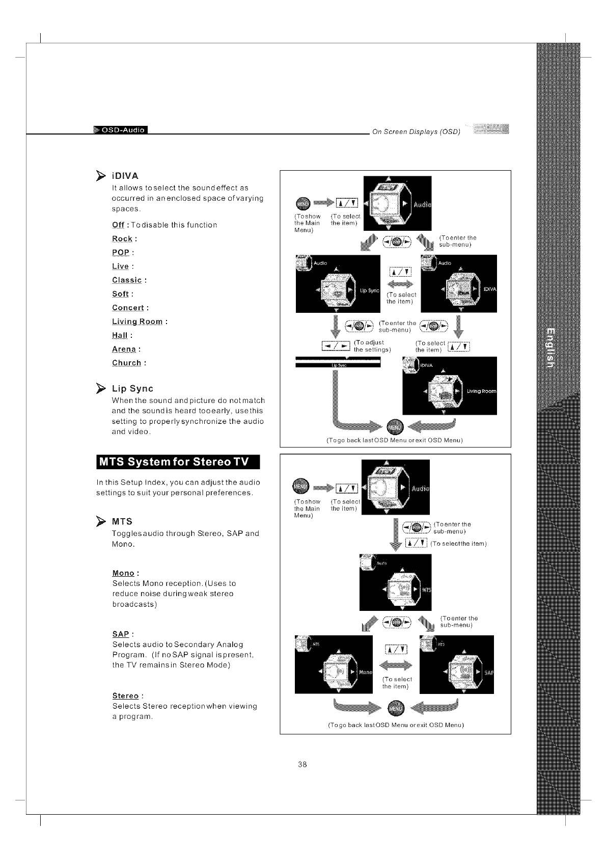
iDIVA
It allows toselect the soundeffect as
occurred in anenclosed space of varying
spaces.
Of{ : Todisable this function
POP :
Live :
Classic :
Soft :
Concert :
LNingRoom:
Ha!! :
Arena
Church :
_;_ Lip Sync
When the sound and picture do not match
and the soundis heard tooearly, usethis
setting to properlysynchronize the audio
and video.
(Toshow
the Main
Menu)
(To select
the item)
_1111" _/_)_ (To enter the.............. sub-menu)
r-G-7--_-i (To adjust (To select F7--_
L____-C______.Jthe settings) the item) L_../-...T..I
(Togo back lastOSD Menu or exit OSD Menu)
In this Setup Index, you can adjust the audio
settings to suit your personal preferences.
MTS
Togglesaudio through Stereo, SAP and
Mono.
Mono :
Selects Mono reception. (Uses to
reduce noise duringweak stereo
broadcasts)
SAP :
Selects audio toSecondary Analog
Program. (If noSAP signal ispresent,
the TV remainsin Stereo Mode)
Stereo :
Selects Stereo receptionwhen viewing
a program.
[Z-_7_-_f_-j
(Toshow (To select
the Main the item)
Menu)
(To select
the item)
(Togo back lastOSD Menu orexit OSD Menu)
38
On Scree n Displays (0 SD)
Screen OSD Adjusting Screen Modes
V.Position
Fine Tune
Auto Sync
Aspect Ratio Aspect, Full Screen, It allows you to select the aspect ratio of the picture you
Panoramic, Zoom 1, are watching.
Zoom 2,1:l Mode
Cropping On, Off (Off, Minimum, Crops image and then enlarges it to fill the screen.
Medium, Maximum)
View Full Screen, PIP, Split Screen It allows you to select the view types of picture modes.
PIP Position Low Right, Low Left, It allows you to change the position of Picture 2.
Upper Right, Upper Left
PIP Size Small, Medium, Large It allows you to change the size of Picture 2.
Swap It allows you to switch the position of Picture1 and Picture2.
Main Picture Source Tunerl,Compositel/2, It allows you to select the main picture or video source
S-Videol/2, Componentl/2, you want to view.
HDMII/2, VGA, VGA-
Component
Sub Picture Source Tunerl,Compositel/2, It allows you to select secondary picture or video source
S-Videol/2, Componentl/2, you want to view.
HDMII/2, VGA, VGA-
Component
Adjustment
H.Position It allows you to adjust the picture position horizontally.
It allows you to adjust the picture position vertically.
It allows you to enhance the picture quality.
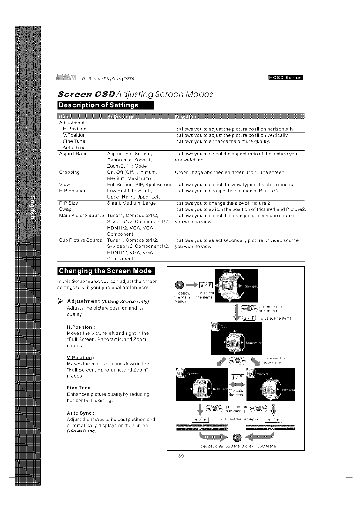
it i_ 1ilq iiI! ii i"1_'_!.'-I4i[-.l-.l ill lvir_l'. 1:
In this Setup Index, you can adjust the screen
settings to suit your personal preferences.
Adjustment (Analog Source Only)
Adjusts the picture position and its
quality.
H.Position :
Moves the pictureleft and rightin the
"Full Screen, Panoramic,and Zoom"
modes.
V.Position :
Moves the pictureup and down in the
"Full Screen, Panoramic,and Zoom"
modes.
Fine Tune:
Enhances picture qualityby reducing
horizontal flickering.
Auto Svnc :
Adjust the imagete its bestposition and
automatically displays onthe screen.
(VGA mode only)
@
(Toshow (To select
the Main the item)
Menu)
(_'/_/'l_! _ (To enterthe
.............. sub-menu)
(_'/_7_) (Toenter the _'_'/_'7_.............. sub-menu) '._L_L../
[-,-.__-::77::__-:l (To adjustthe settings)[ :_-_-::Z: 7.__-_-:l
(Togo back lastOSD Menu orexit OSD Menu)
39
On Screen Displays (OSD)
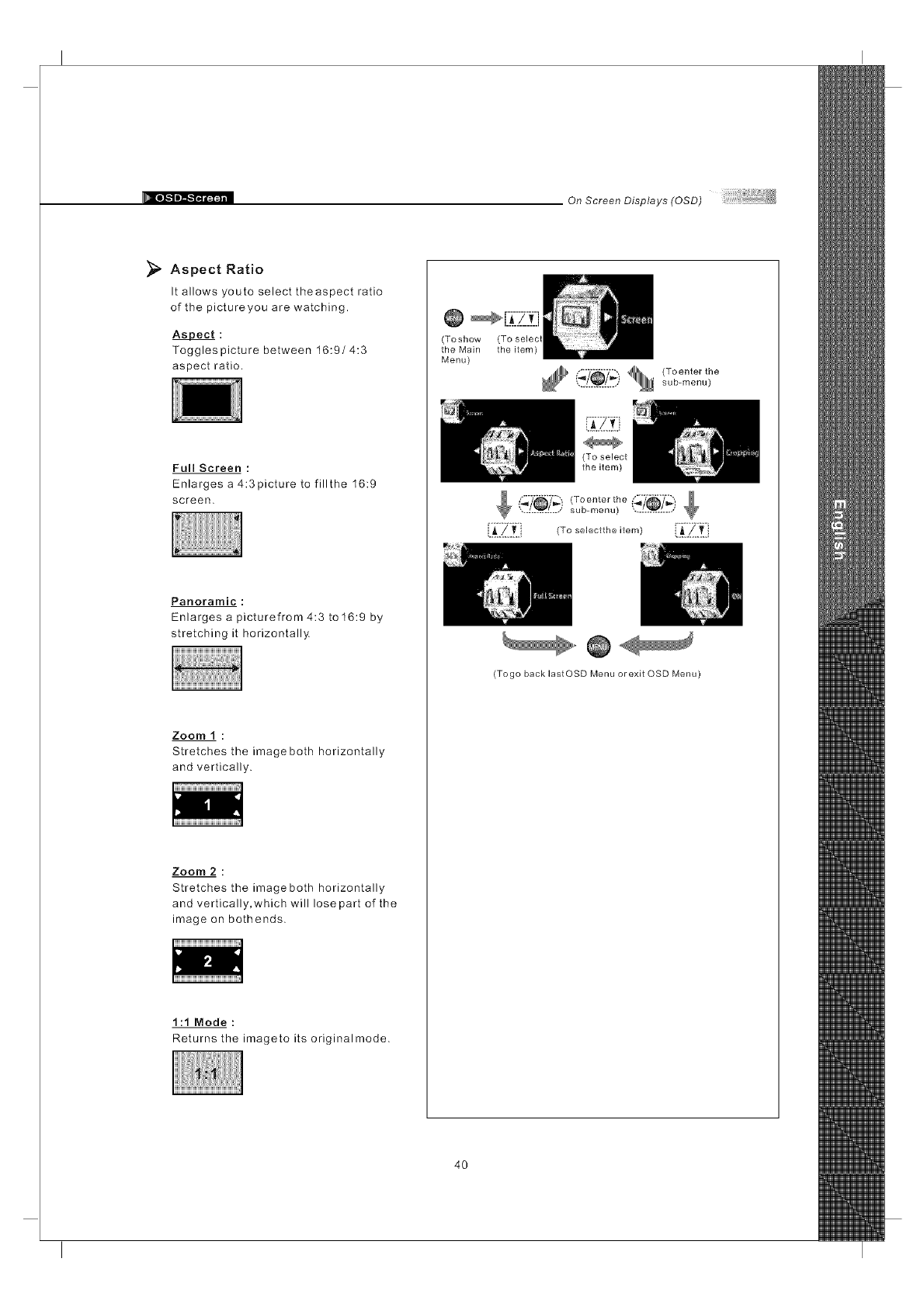
Aspect Ratio
It allows youto select theaspect ratio
of the pictureyou are watching.
A$Bect :
Toggles picture between 16:9/4:3
aspect ratio.
FullScreen :
Enlarges a 4:3picture to fillthe 16:9
screen.
Panoramic :
Enlarges a picturefrom 4:3 to 16:9 by
stretching it horizontally.
Zoom 1 :
Stretches the image both horizontally
and vertically.
Zoom 2 :
Stretches the image both horizontally
and vertically, which will lose part of the
image on bothends.
1:1 Mode :
Returns the imageto its originalmode.
(Toshow (To selec
the Main the item)
Menu)
i_'_7_ ) _ (To enter the............... sub-menu)
sub-menu) "._L_L..,,'
[:A'.:_.:_:i (To selectthe item) i:A::_.::_:i
(Togo back lastOSD Menu or exit QSD Menu)
4O
On Screen Displays (OSD)
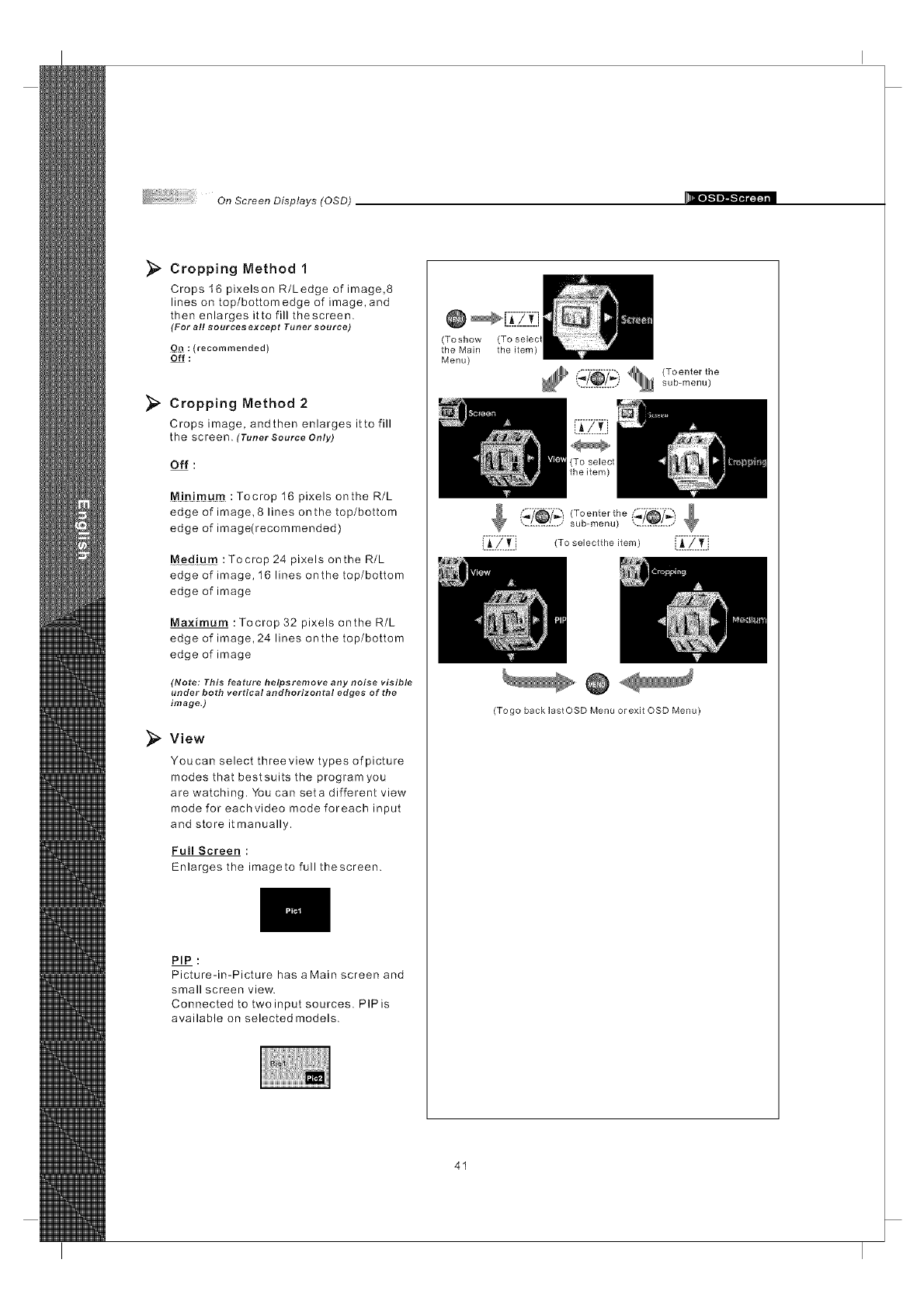
_" Cropping Method 1
Crops 16 pixelson R/Ledge of image,8
lines on top/bottom edge of image, and
then enlarges itto fill thescreen.
(For all sources except Tuner source)
Qn : (recommended)
Off :
_, Cropping Method 2
Crops image, andthen enlarges itto fill
the screen. (Tuner Source Only)
Off :
M!nimum : Tocrop 16 pixels onthe R/L
edge of image, 8 lines onthe top/bottom
edge of image(recommended)
Medium :Tocrop 24 pixels onthe R/L
edge of image, 16 lines onthe top/bottom
edge of image
Maximum : Tocrop 32 pixels onthe R/L
edge of image,24 lines onthe top/bottom
edge of image
(Note: This feature helpsremove any noise visible
under both vertical andhorizontal edges of the
image.)
View
Youcan select threeview types of picture
modes that bestsuits the programyou
are watching. You can seta different view
mode for eachvideo mode foreach input
and store it manually.
Full Screen :
Enlarges the imageto full thescreen.
PIP :
Picture-in-Picture has aMain screen and
small screen view.
Connected to twoinput sources. PIPis
available on selected models.
(Toshow
the Main
Menu)
(To selec
the item)
(_7_ i _ (To enter the............... sub-menu)
sub-menu) ...L_L..,/
..........................
i.A.!...l[., (To selectthe item) i.__ _.._.i
(Togo back lastOSD Menu or exit OSD Menu)
41
On Screen Displays (OSD)
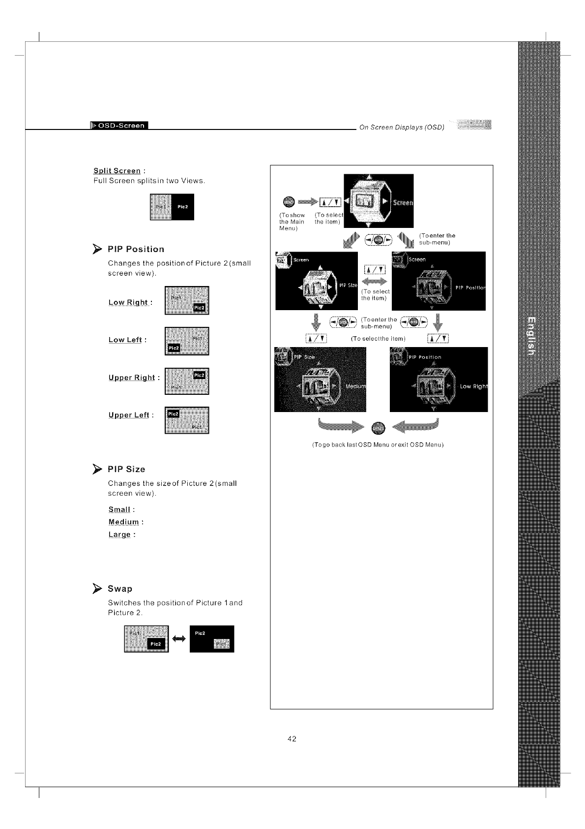
Split Screen :
Full Screen splitsin two Views.
_, PtP Position
Changes the positionof Picture 2(small
screen view).
Low Left :
Upper Right :
Upper Left :
PiP Size
Changes the sizeof Picture 2(small
screen view).
Sina!! :
Medium :
_#[g_ :
Swap
Switches the positionof Picture 1 and
Picture 2.
(Toshow
the Main
Menu)
(To selec
the item)
""1111111 (Toenterthe............... sub-menu)
sub-menu) ',...L_L..,,'
['i_-ZI_I} (To seieotthe item) ['_:'ZI_:I
(Togo back lastOSD Menu or exit OSD Menu)
42
On Screen Displays (OSD)
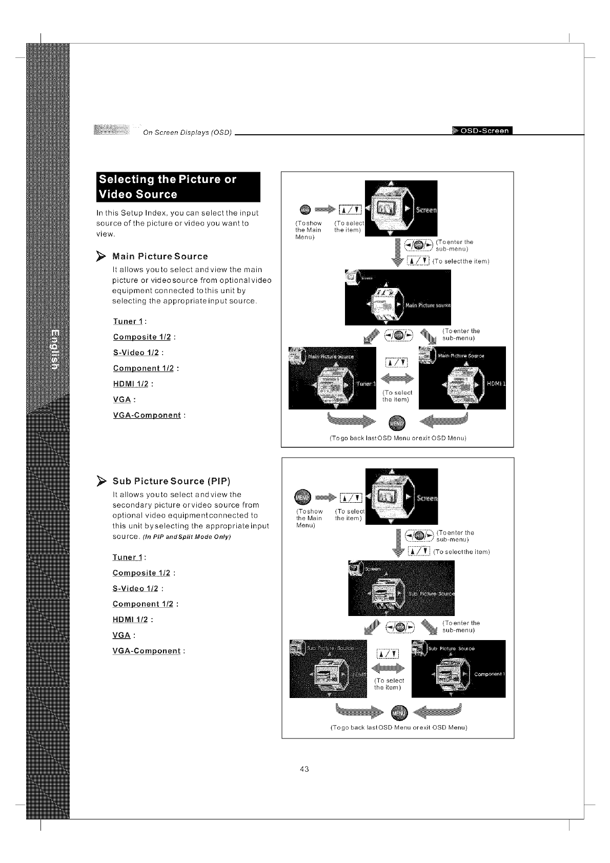
In this Setup Index, you can select the input
source of the picture or video you want to
view.
_" Main PictureSource
It allows youto select andview the main
picture or videosource from optionalvideo
equipment connected tothis unit by
selecting the appropriateinput source.
Tuner 1 :
Composite 1/2 :
S-Video 1/2 :
Component 1/2 :
HDMI 1/2 :
VGA :
VGA-Component :
@
(Toshow (To selecl
the Main the item)
Menu)
.............. sub-menu)
(To select
the item)
(Togo back lastOSD Menu orexit OSD Menu)
Sub Picture Source (PIP)
It allows youto select andview the
secondary picture orvideo source from
optional video equipmentconnected to
this unit byselecting the appropriateinput
sou rce. (In PIP andSplit Mode Only)
Tuner 1 :
Composite 1/2 :
S-Video 1/2 :
Component 1/2 :
HDMI 1/2 :
VGA :
VGA-Component :
(Toshow (To selec
the Main the item)
Menu)
.............. sub-menu)
L_..L.[i
(To select
the item)
(Togo back lastOSD Menu orexit OSD Menu)
43
On Screen Displays (OSD)
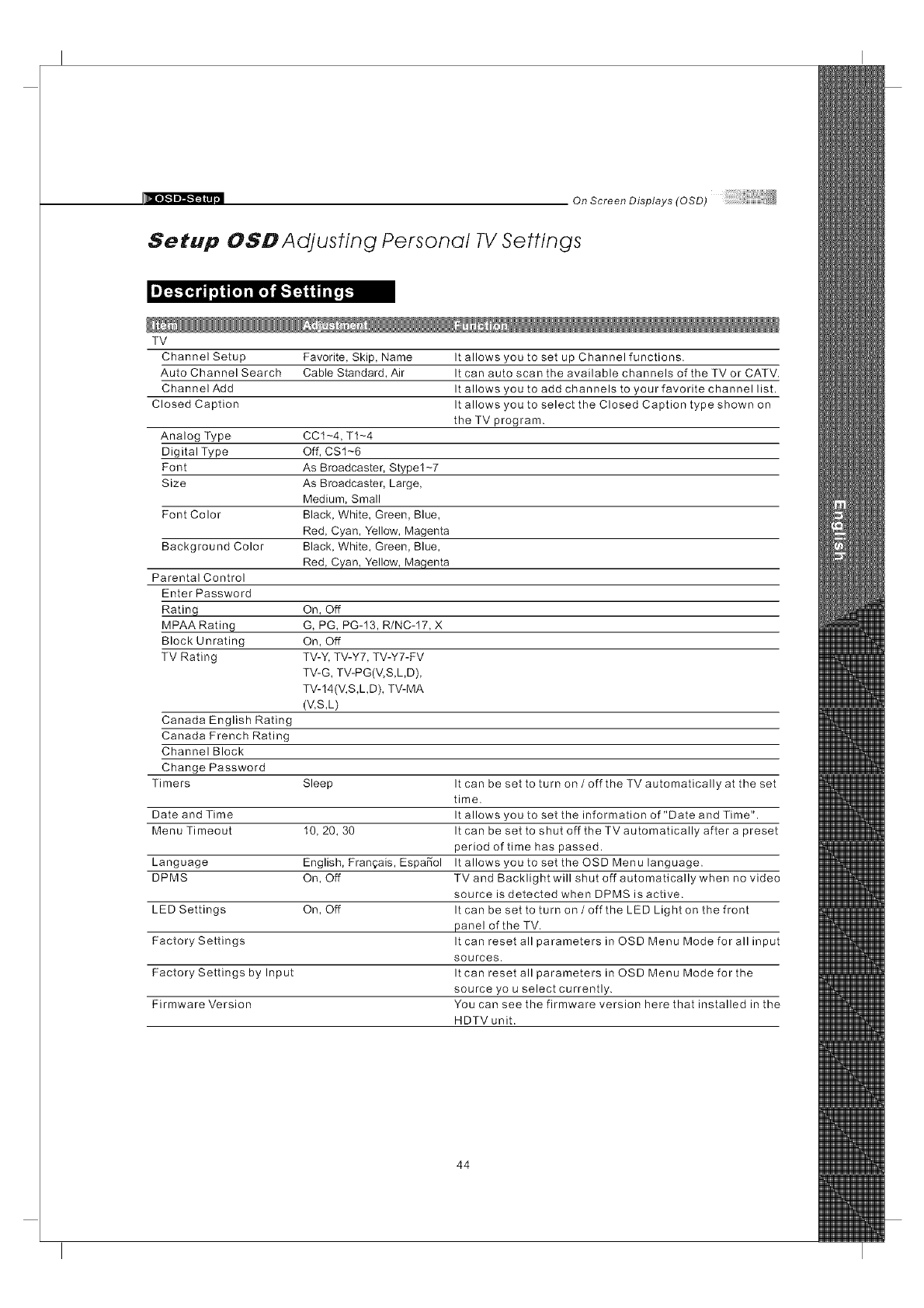
Setup OSD Adjusting Personal TV Settings
TV
Favorite, Skip, Name
Cable Standard, Air
Channel Setup
Auto Channel Search
Channel Add
Closed Caption
Analog Type CCt-4, T1-4
Digital Type Off, CS1-6
Font As Broadcaster, Stypel-7
Size As Broadcaster, Large,
Medium, Small
Font Color Black, White, Green, Blue,
Red, Cyan, Yellow, Magenta
Background Color Black, White, Green, Blue,
Red, Cyan, Yellow, Magenta
It allows you to set up Channel functions.
It can auto scan the available channels of the TV or CATV.
It allows you to add channels to your favorite channel list.
It allows you to select the Closed Caption type shown on
the TV program.
Parental Control
Enter Password
Rating On, Off
MPAA Rating G, PG, PG-13, R/NC-17, X
Block Unrating On, Off
TV Rating TV-Y, TV-Y7, TV-Y7-FV
TV-G, TV-PG(V,S,LD),
TV-14(V,S,LD), TV-MA
(V,S,L)
Canada English Rating
Canada French Rating
Channel Block
Change Password
Timers Sleep It can be set to turn on /off the TV automatically at the set
time.
Date and Time It allows you to set the information of "Date and Time".
Menu Timeout 10, 20, 30 It can be set to shut off the TVautomatically after a preset
period of time has passed.
Language English, Fran_ais, EspaSol It allows you to set theOSDMenulanguage.
DPMS On, Off TV and Backlight will shut off automaticallywhen no video
source is detected when DPMS is active.
LED Settings On, Off It can be set to turn on /off the LED Light on the front
panel of the TV.
Factory Settings It can reset all parameters in OSD Menu Mode for all input
sources.
Factory Settings by Input It can reset all parameters in OSD Menu Mode for the
source you select currently.
Firmware Version You can see the firmware version here that installed in the
HDTV unit.
44
On Screen Displays (OSD)
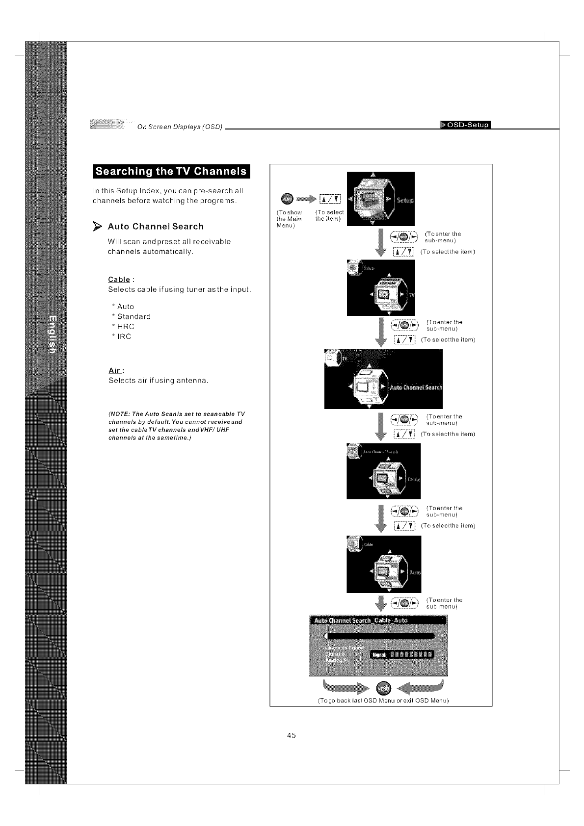
,'l-.-f..1iI4 ill il! i i i_ lillll! il_. 1il il-.l !
In this Setup Index, you can pre-search all
channels before watching the programs.
Auto Channel Search
Will scan and preset all receivable
channels automatically.
Cable :
Selects cable if using tuner asthe input.
* Auto
* Standard
* HRC
* IRC
Air:
Selects air if using antenna.
(NOTE: The Auto Scanis set to scancable TV
channels by default. You cannot receiveand
set the cable TV channels andVHF/ UHF
channels at the sametime.)
@ _ {7_7_-7f]i
(Toshow (To select
the Main the item)
Menu)
(_'/_'7_ i (To enter the
.............. sub-menu)
/ i 7 77 oonto,t,-,o
sub-menu)
{i_-Zit]_To_o,octt,-,o,tom_
Toenter the
sub-menu)
45
(Togo back last OSD Menu orexit OSD Menu)
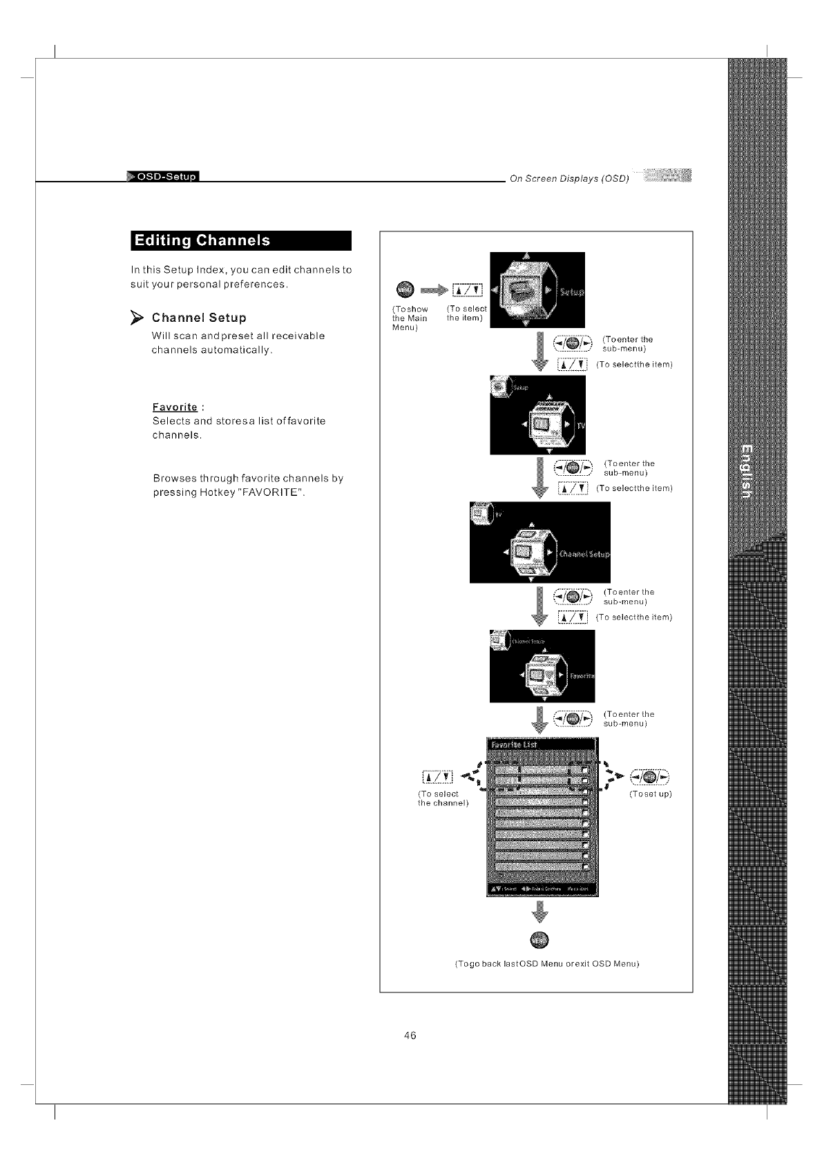
On Screen Displays (OSD)
_ [_
In this Setup Index, you can edit channels to
suit your personal preferences.
_" Channel Setup
Will scan and preset all receivable
channels automatically.
Favorite :
Selects and storesa list offavorite
channels.
Browses through favorite channels by
pressing Hotkey "FAVORITE".
@ [.7-_-Z-.f;]
(Toshow (To select
the Main the item)
Menu)
'_) (Toenter the
............. sub-menu)
[:_'Zit i} (To selectthe item)
(_7_'7_) (Toenter the
.............. sub-menu)
!._.Z..T.., To selectthe item)
Toenter the
sub-menu)
i._..4.v.i
(To select
the channel) (Toset up)
(Togo back lastOSD Menu orexit OSD Menu)
46
OnScreenDisplays(OSD)
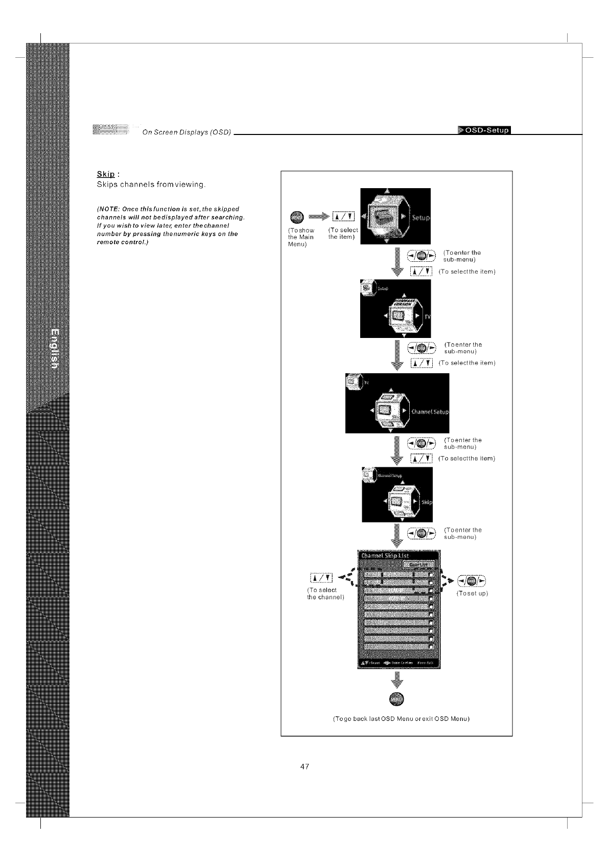
SkiD:
Skips channels fromviewing.
(NOTE: Once thisfunction is set, the skipped
channels will not bedisplayed after searching.
If you wish to view later, enter thechannel
number by pressing thenumeric keys on the
remote control.)
(Toshow (To select
the Main the item)
Menu)
;./@// (Toenter the
sub-menu)
[_.._.,_.i (To selectthe item)
_7_,_ " (Toenter the
............... sub-menu)
i.A.._.._.i (To selectthe item)
Toonte,tho
• sub-menu)
(To select
the channel) (Toset up)
(Togo back last OSD Menu or exit OSD Menu)
47
On Screen Displays (OSD)
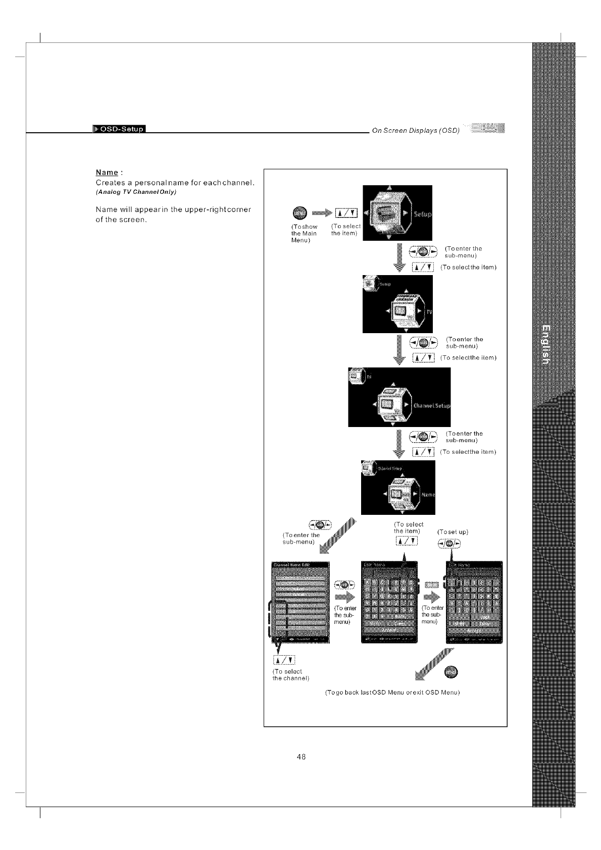
Name :
Creates a personal name for each channel.
(Analog TV ChannelOnly)
Name will appearin the upper-rightcorner
of the screen. Q r.: zzJ
(Toshow (To select
the Main the item)
Menu)
sub-menu)
{:_:/::T.:i (To selectthe item)
_i_) (To enter the
............... sub-menu)
' [_.!.._.i (To selectthe item)
(_/_) (To enter the
.............. sub-menu)
[:i::?:'t:] (To selectthe item)
(To select
the item) (Toset up)
{J.Z!]
(To select
the channel)
(Togo back lastOSD Menu orexit OSD Menu)
48
On ScreenDisplays(OSD)
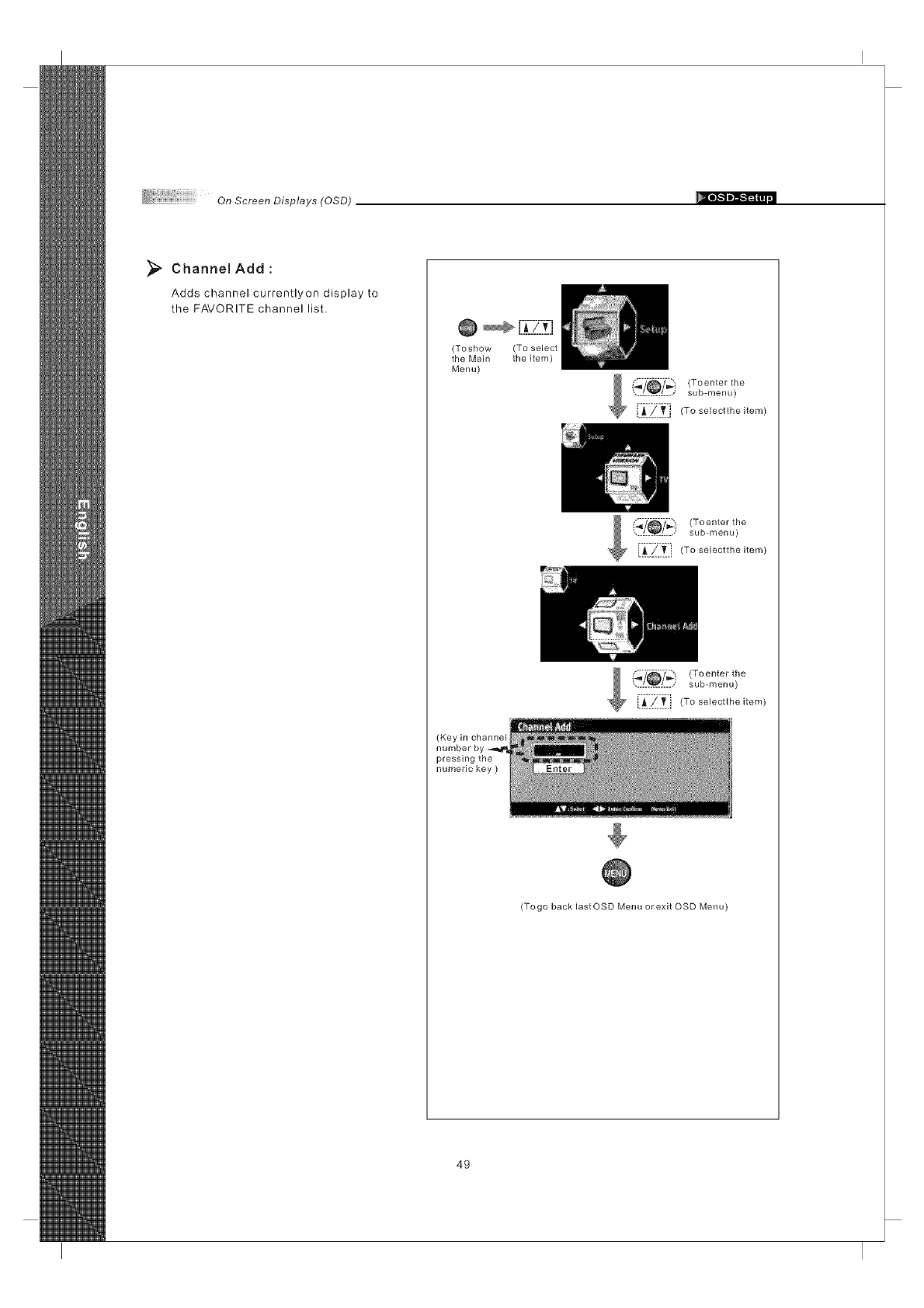
_, Channel Add
Adds channel currentlyon display to
the FAVORITE channel list.
@ _-[_;.-2-_-_t-J
(Toshow (To select
the Main the item)
Menu)
('_'/_7_- (Toenter the
............. sub-menu)
[_:Z.ti!_Toso,ecttheitem)
(Key in channel
pressing the
numeric key )
,oeote,the
sub-menu)
x_ E:_:_}_:i (To selectthe item)
(Togo back lastOSD Menu or exit OSD Menu)
49
On Screen Displays (OSD)
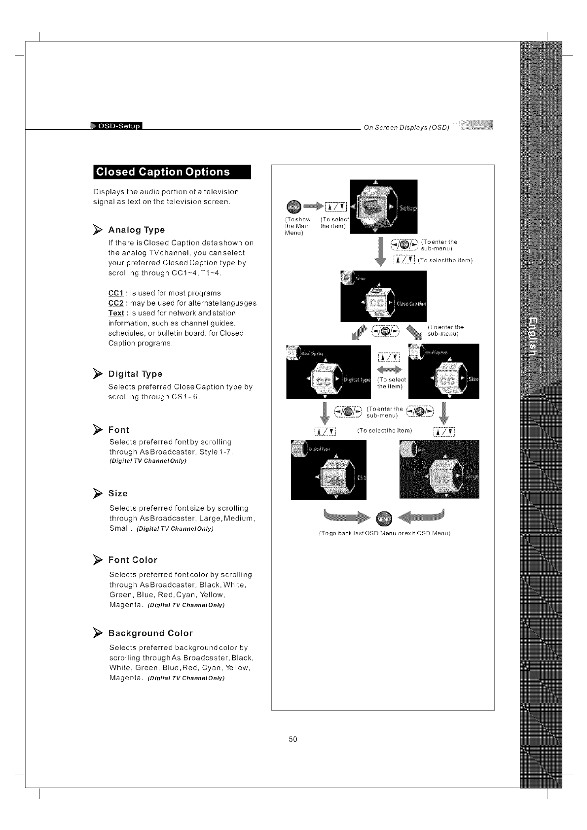
Displays the audio portion of a television
signal as text on the television screen.
Analog Type
If there isClosed Caption datashown on
the analog TVchannel, you canselect
your preferred ClosedCaption type by
scrolling through CC1-4,T1-4.
CC:! :is used for most programs
CC2 :may be used for alternate languages
Text :is used for network andstation
information, such as channel guides,
schedules, or bulletin board, for Closed
Caption programs.
Digital Type
Selects preferred CloseCaption type by
scrolling through CS1- 6.
Font
Selects preferred font by scrolling
through As Broadcaster, Style1-7.
(Digital TV Channel Only)
_" Size
Selects preferred fontsize by scrolling
through As Broadcaster, Large, Medium,
Small. (Digital TV ChannelOn/y)
_, Font Color
Selects preferred fontcolor by scrolling
through As Broadcaster, Black, White,
Green, Blue, Red,Cyan, Yellow,
Magenta. (Digital TV ChannelOnly)
_" Background Color
Selects preferred backgroundcolor by
scrolling throughAs Broadcaster, Black,
White, Green, Blue,Red, Cyan, Yellow,
Magenta. (Digital TV ChannelOnly)
(Toshow
the Main
Menu)
(To selec
the item)
............... sub-menu)
,o,ec,,,-,e,,em
(Togo back last OSD Menu orexit OSD Menu)
5O
OnScreenDisplays(OSD)
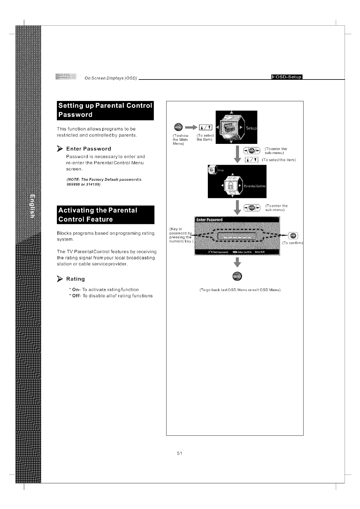
This function allows programs to be
restricted and controlledby parents.
Enter Password
Password is necessaryto enter and
re-enter the Parental Control Menu
screen.
(NOTE: The Factory Default passwordis
999999 or 314159)
Blocks programs based onprograming rating
system.
The TV ParentalControl features by receiving
the rating signal fromyour local broadcasting
station or cable serviceprovider.
Rating
* On- To activate ratingfunction
* Off- To disable allof rating functions
Q_-[_i-71t-j
(Toshow (To select
the Main the item)
Menu)
(_'/_y_) (Toenter the
.............. sub-menu)
E_:__:!_Toso,ectt,,e,tem_
(Toenter the
sub-menu)
(Key in
numeric key )
(Togo back lastOSD Menu or exit OSD Menu)
51
On Screen Displays (OSD)
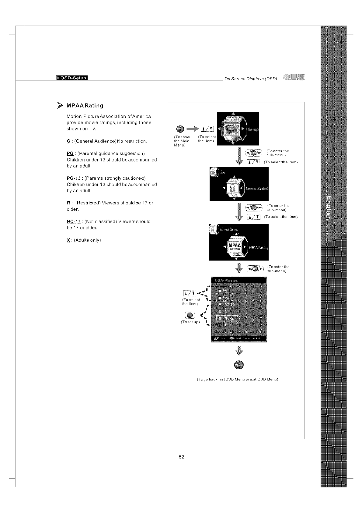
};_ MPAA Rating
Motion PictureAssociation of America
provide movie ratings, including those
shown on TV.
G : (General Audience) No restriction.
PG : (Parental guidance suggestion)
Children under 13 should beaccompanied
by an adult.
PG-13 : (Parents strongly cautioned)
Children under 13 should beaccompanied
by an adult.
R : (Restricted) Viewers should be 17 or
older.
NC:!Z : (Not classified) Viewers should
be 17 or older.
: (Adults only)
(Toshow (To select
the Main the item)
Menu)
1 _?_y'_ (To enter the
............... sub-menu)
i.A/_ To selectthe item)
(,_?_/_,i (Toenter the
............... sub-menu)
(To select _ =
the item) I
<
(Toset up) |
(Togo back lastOSD Menu orexit OSD Menu)
52
On ScreenDisplays(OSD)
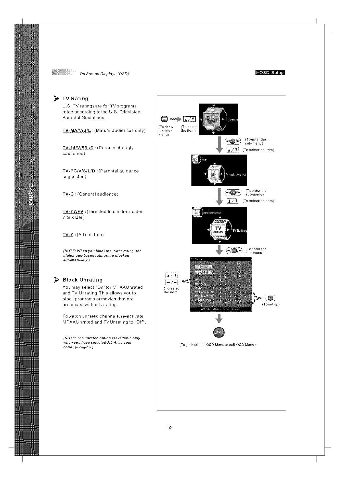
_, TV Rating
U.S. TV ratings are for TVprograms
rated according tothe U.S. Television
Parental Guidelines.
TytMA/_!IStL :(Mature audiences only)
TY:!4LV!SZgI_ :(Parents strongly
cautioned)
TV.PGIVlSILID : (Parental guidance
suggested)
TV-G :(General audience)
TV-Y7/FV :(Directed to children under
7 or older)
TV-Y :(All children)
(NOTE: When you blockthe lower rating, the
higher age- based ratings are blocked
automatically.)
_, Block Unrating
You may select "On"for MPAAUnrated
and TV Unrating.This allows youto
block programs ormovies that are
broadcast without arating.
Towatch unrated channels, re-activate
MPAAUnrated and TVUnrating to "Off".
(NOTE: The unrated option isavailable only
when you have selectedU.S.A, as your
country/region.)
@ r_:i_-ZZi
(Toshow (To select
the Main the item)
Menu)
_,'_-/_"_') (Toenter the
............... sub-menu)
i._.._..T._, (To selectthe item)
(_y_.) (Toenter the
............... sub-menu)
i.$./.._ i (To selectthe item)
!,'._ (To enter the
.............. sub-menu)
[ ZB
(To select
the item)
(Toset up)
(Togo back last OSD Menu orexit OSD Menu)
53
On Screen Displays (OSD)
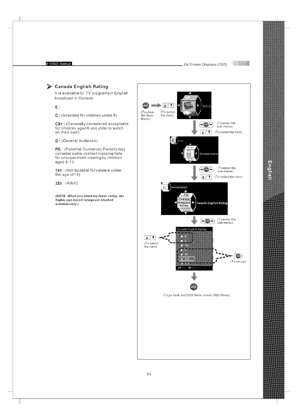
_;_ Canada English Rating
It is availablefor TV programsin English
broadcast in Canada.
E:
C : (Intended for children under 8)
C8+ :(Generally considered acceptable
for children aged8 and olderto watch
on their own)
G : (General Audience)
PG : (Parental Guidance) Parentsmay
consider some contentinappropriate
for unsupervised viewing by children
aged 8-13.
14+ : (Not suitable forviewers under
the age of 14)
18+ : (Adult)
(NOTE: When you blockthe lower rating, the
higher age-based ratings are blocked
automatically.)
(Toshow (To select
the Main the item)
Menu)
(_/_/_i (Toenter the
............... sub-menu)
[i_i_ii_ii (To seiectthe item
i_?_7-_" _ (Toenter the
............... sub-menu)
i._./..._. '(To select:he item
(To select
the item)
(_y_) (To enter the
............... sub-menu)
_t (Toset up)
(Togo back lastOSD Menu orexit OSD Menu)
54
On ScreenDisplays(OSD)
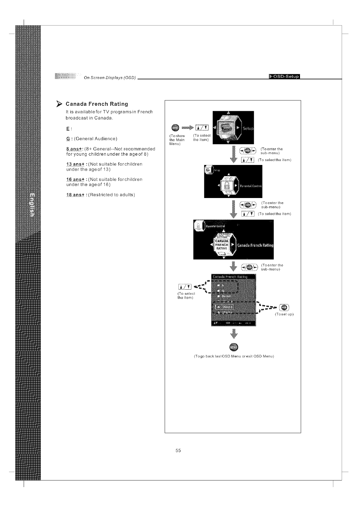
_;_ Canada French Rating
It is availablefor TV programsin French
broadcast in Canada.
E:
: (General Audience)
8#he±:(8+ General--Not recommended
for young childrenunder the age of 8)
13 ans+ :(Not suitable forchildren
under the ageof 13)
16 ans+ :(Not suitable forchildren
under the ageof 16)
18 ans+ :(Restricted to adults)
@
(Toshow (To select
the Main the item)
Menu)
.............. sub-menu)
E_II_.t] (To se]ectthe item)
I _7_Y_ (To enter the
............... sub-menu)
i_j_, (To se]ectthe item)
[ilZt] ,.,.a"
(To select _"=
the item)
('_'_ _')(Toenter the
.............. sub-menu)
(Toset up)
(Togo back lastOSD Menu orexit OSD Menu)
55
On Screen Displays (OSD)
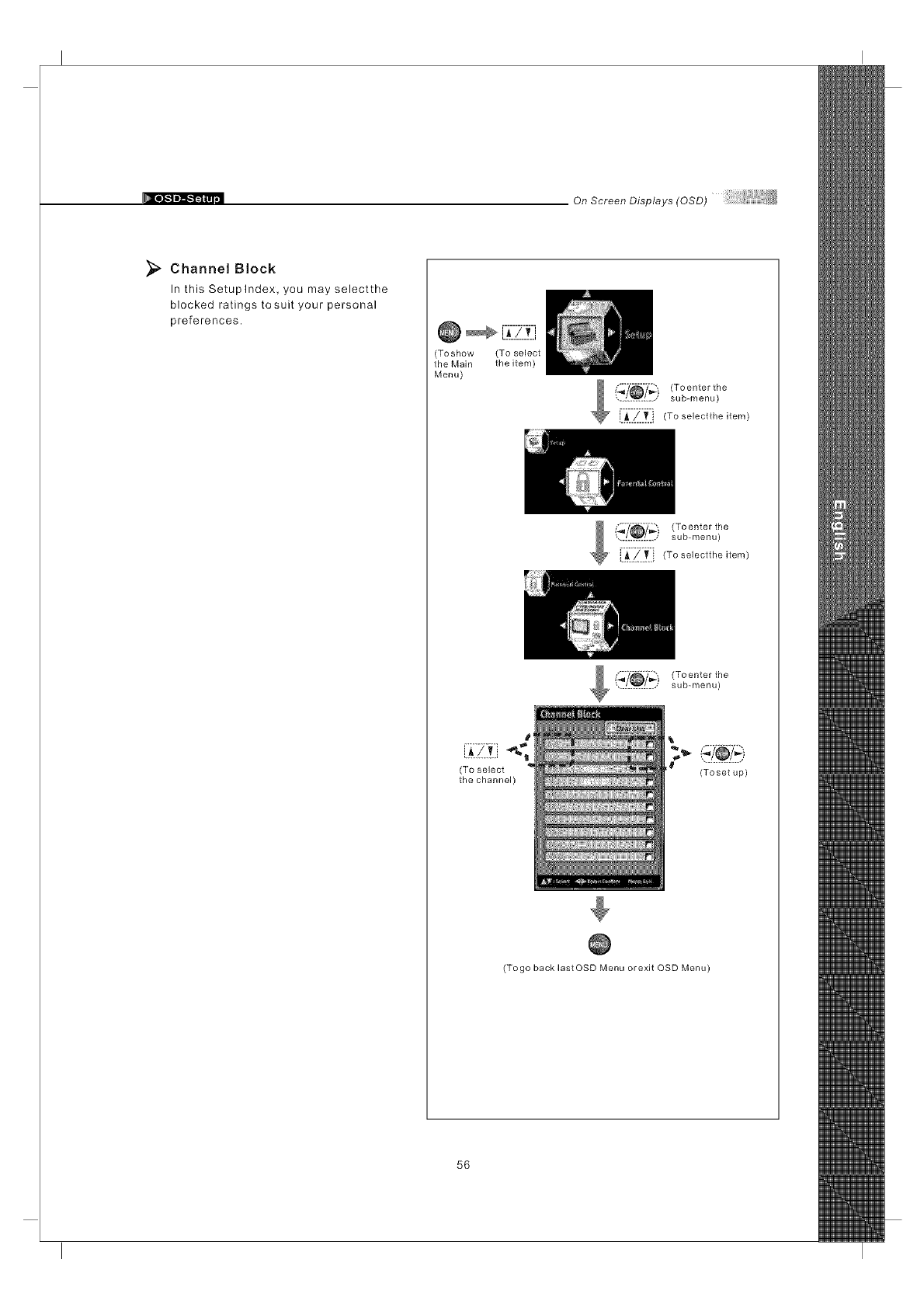
Channel Block
In this Setuplndex, you may selectthe
blocked ratings tosuit your personal
preferences.
(Toshow (To select
the Main the item)
Menu)
_ {,'._ (To enter the
.............. sub-menu)
i._..!..T..i (To selectthe item)
I (_'?_?_:) (Toenter the
.............. sub-menu)
i._../' _ i (To selectthe item)
_ (_"[_/_i (To enter the
.............. sub-menu)
(To select
the channel) (Toset up)
(Togo back lastOSD Menu orexit OSD Menu)
56
OnScreenDisplays(OSD)
_1 _J
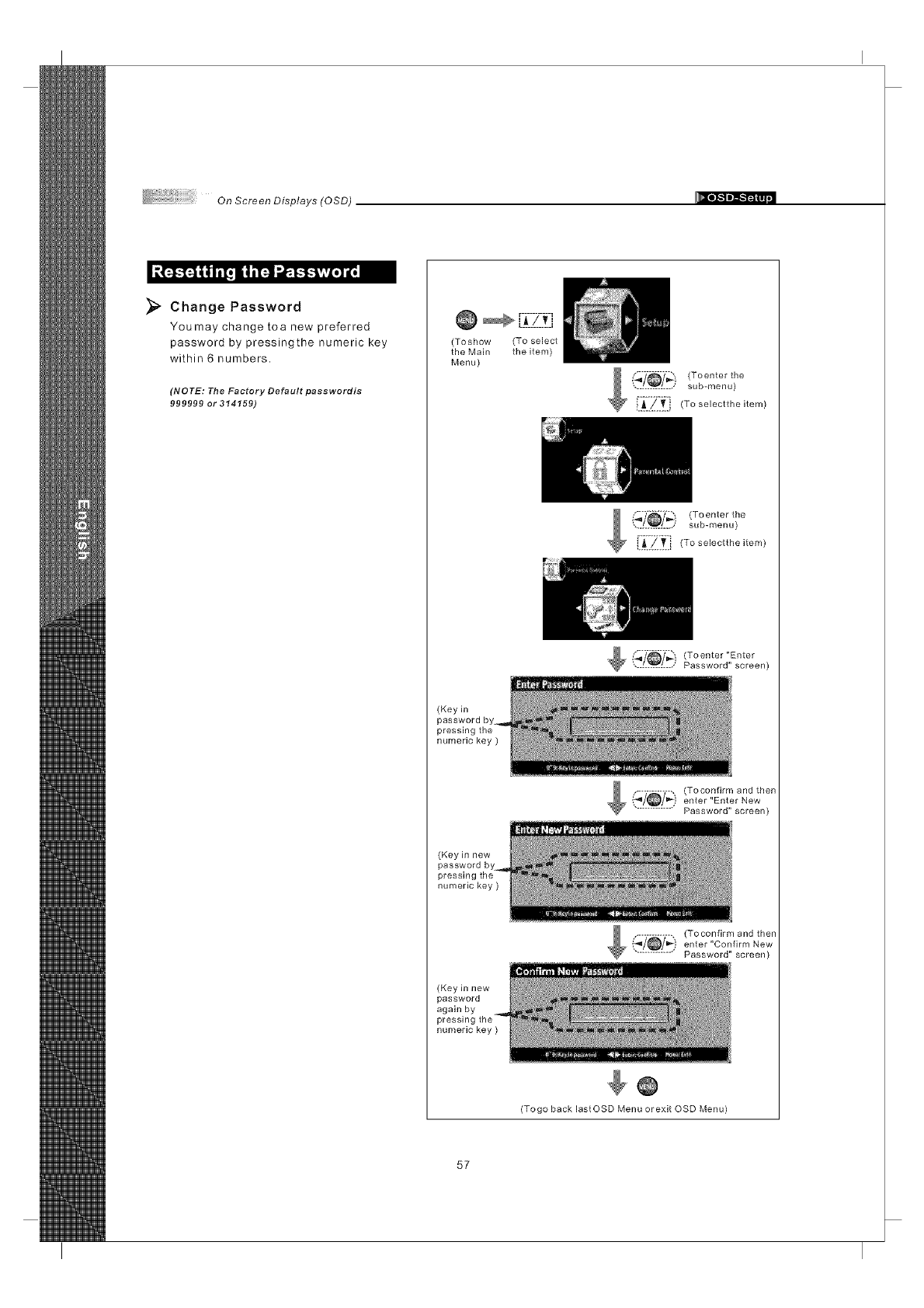
Change Password
Youmay change toa new preferred
password by pressingthe numeric key
within 6 numbers.
(NOTE: The Factory Default passwordis
999999 or 314159)
(Toshow (To select
the Main the item)
Menu)
sub-menu) T°ente"the
i :ZIL (Tose,ectthe,tom
{_.i!_}i (Toenter the
sub-menu)
[ii_-Z }_i } (To selectthe item)
(_'_i!_!_) (To enter "Enter
Password" screen)
(Key in
password by_
pressing the
numeric key )
$ (_i!_!--_} (T .... fi .... d then
enter "Enter New
Password" screen)
(Keyinnew
password by
pressing
numeric key)
(Keyinnew
password
again by
numeric key )
_(_-_,) (Toconfi .... dthen
enter "Confirm New
............... Password" screen)
(Togo back lastOSD Menu orexit OSD Menu)
57
On Screen Displays (OSD)
.IF_iiii[t it ='IFJIm_ (:_.li[, IId tii [=1=
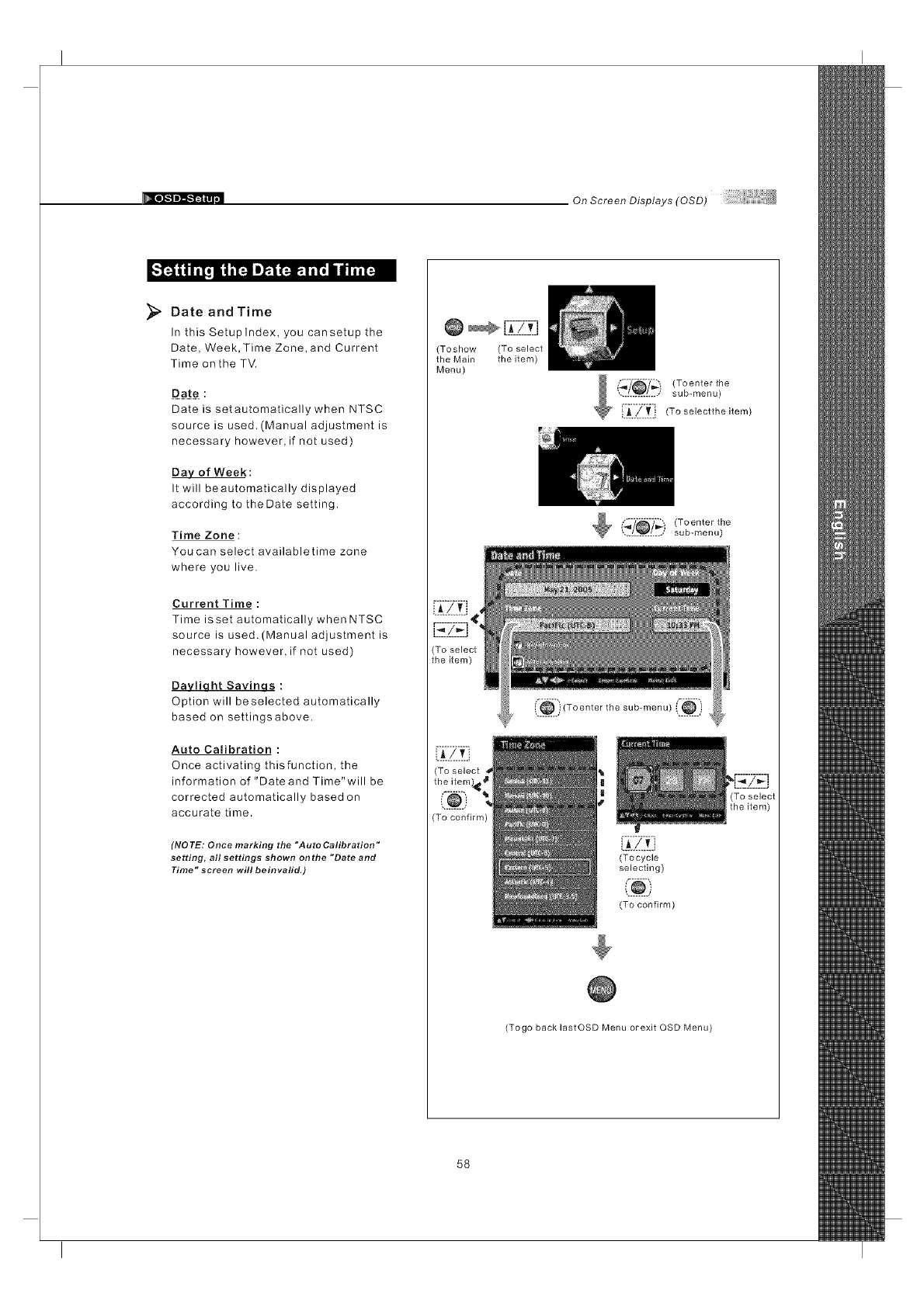
Date and Time
In this Setuplndex, you cansetup the
Date, Week, Time Zone,and Current
Time onthe TV.
Date is setautomatically when NTSC
source is used. (Manual adjustment is
necessary however, if not used)
Day of Week:
It will beautomatically displayed
according to theDate setting.
Time Zone :
You can select availabletime zone
where you live.
Current Time:
Time isset automatically when NTSC
source is used. (Manual adjustment is
necessary however, if not used)
Davliaht Savinas :
Option will beselected automatically
based on settingsabove.
Auto Calibration :
Once activating thisfunction, the
information of "Date and Time"will be
corrected automatically based on
accurate time.
(NO TE: Once marking the "Auto Calibration"
setting, all settings shown onthe "Date and
Time" screen will beinvalid.)
@[-i_-_-Z_t]
(Toshow (To select
the Main the item)
Menu)
sub-menu)
_ ["ii711_ii (To selecttheitem)
Toenter the
sub-menu)
(To confirm)
('®) Toente,t,,o,ub........
(Tocycle
selecting)
(To confirm)
(Togo back lastOSD Menu orexit OSD Menu
58
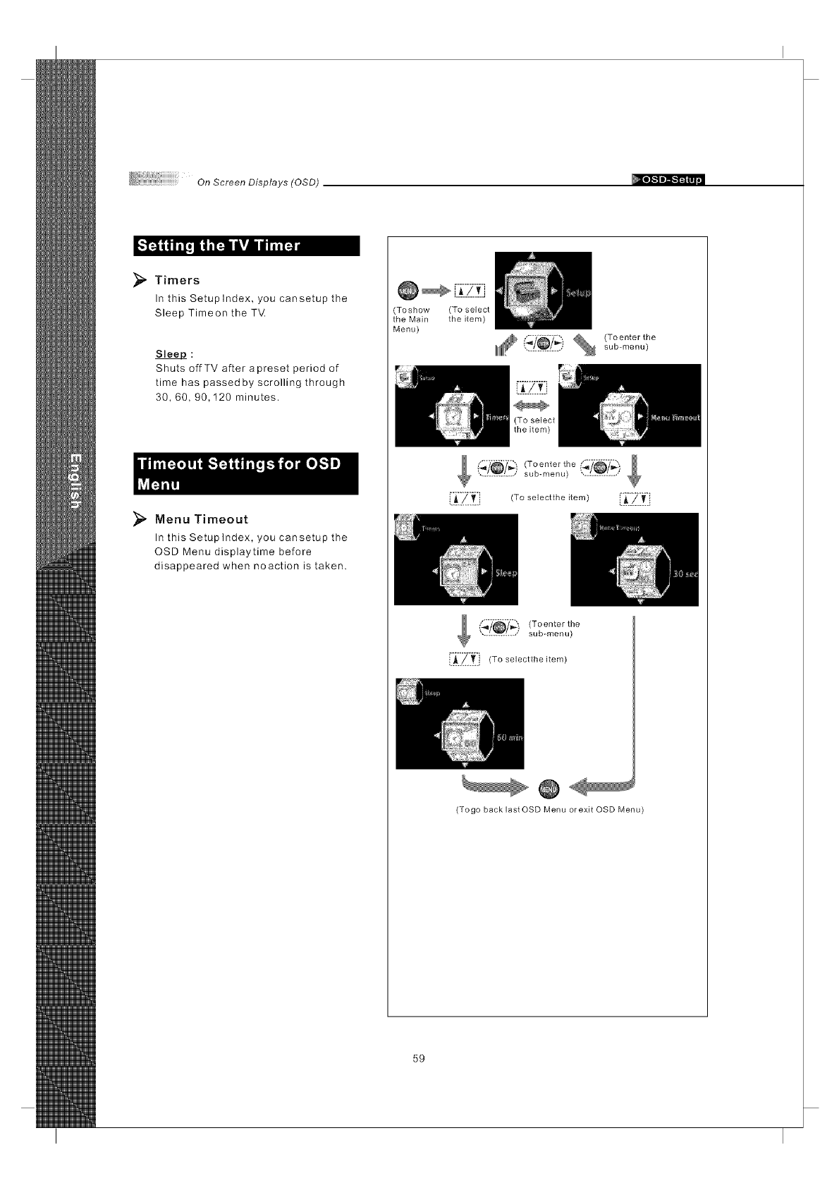
On ScreenDisplays(OSD)
_, Timers
In this Setuplndex, you cansetup the
Sleep Timeon the TV
Slee#_ :
Shuts offTV after a preset period of
time has passed by scrolling through
30, 60, 90,120 minutes.
_, Menu Timeout
In this Setuplndex, you cansetup the
OSD Menu displaytime before
disappeared when noaction is taken.
Toshow (To select
the Main the item)
Menu)
lil£ (_7_7_)_ (To enterthe
............... sub-menu)
(_7_7_) (Toenterthe _/_7_'_.............. sub-menu) ',...L..V..:....;
!i_i_iltl, (To selectthe item) i__: _.iltli
{fl"/_/_') (Toenter the
............. sub-menu)
[i_i "/i_i j (to selectthe item)
@
(Togo back last OSD Menu orexit OSD Menu)
59
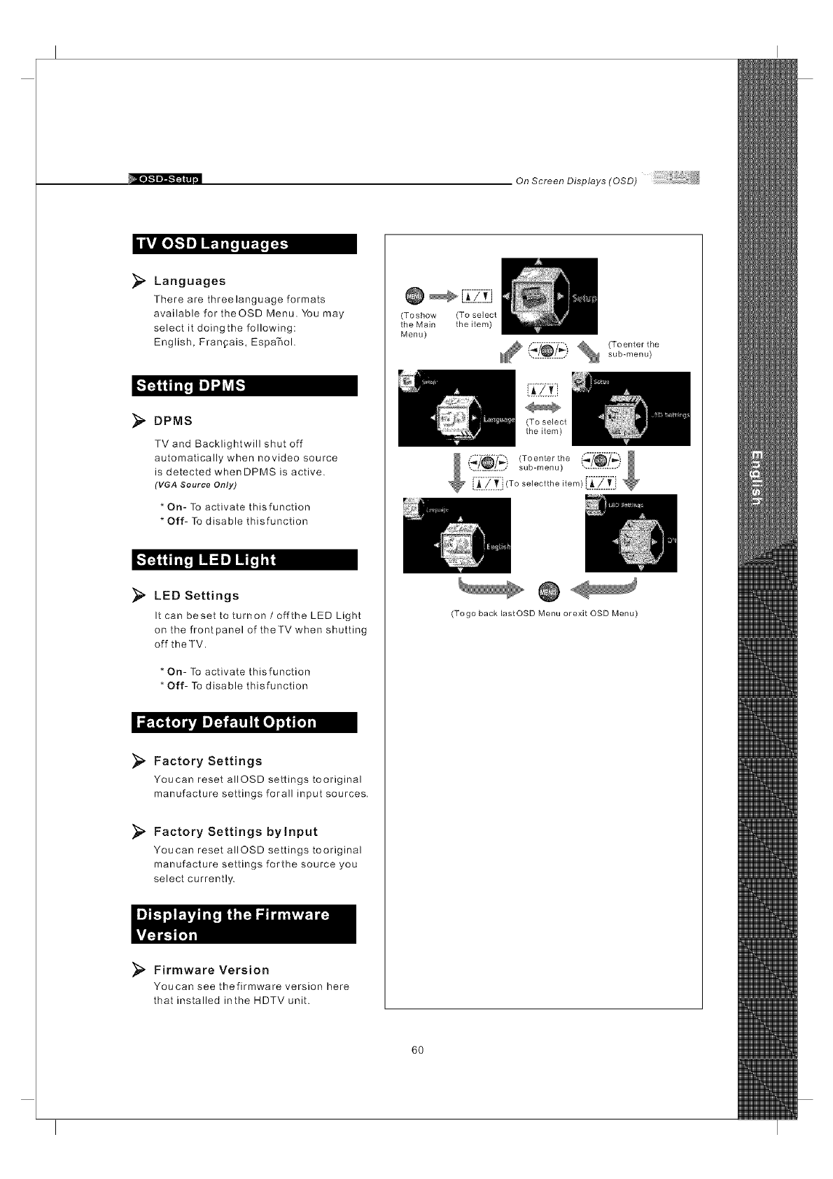
On Screen Displays (OSD)
iul,vA[o][.."]l__]]_...T._]:_]
Languages
There are threelanguage formats
available for theOSD Menu. You may
select it doingthe following:
English, Fran_ais, Espa'_ol.
DPMS
TV and Backlightwill shut off
automatically when novideo source
is detected whenDPMS is active.
(VGA Source Only)
* On- To activate thisfunction
* Off- To disable thisfunction
_" LED Settings
It can beset to turnon /offthe LED Light
on the front panel of theTV when shutting
off the TM.
* On- To activate thisfunction
* Off- To disable thisfunction
_ _O_l t_
Factory Settings
Youcan reset alIOSD settings tooriginal
manufacture settings forall input sources.
_. Factory Settings bylnput
Youcan reset allOSD settings tooriginal
manufacture settings forthe source you
select currently.
_" Firmware Version
Youcan see thefirmware version here
that installed inthe HDTV unit.
@ _ -_:7_-Z]
(Toshow (To select
the Main the item)
Menu)
_?_?_ % (Toenterthe
............... sub-menu)
(To select
the item)
(Togo back lastOSD Menu orexit OSD Menu)
6O
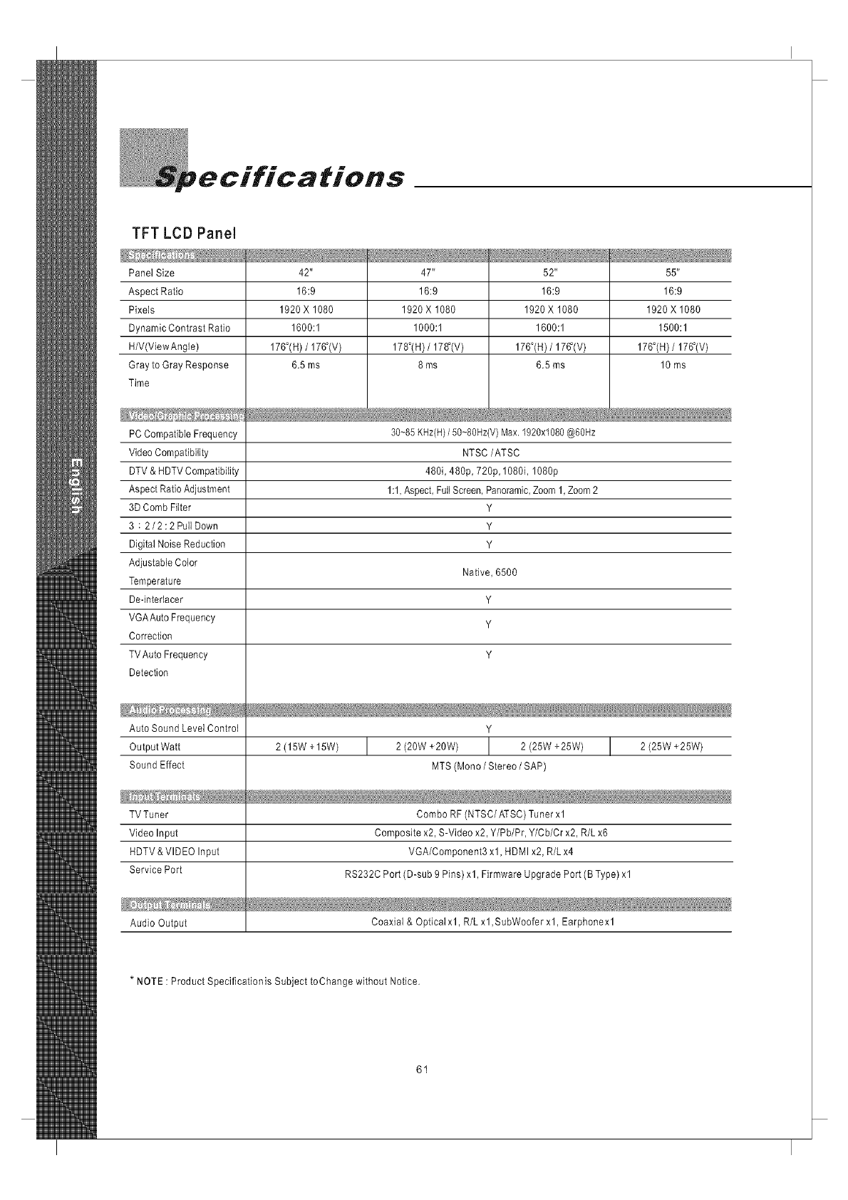
pecifications
TFT LCD Panel
Panel Size 42" 47" 52" 55"
Aspect Ratio 16:9 16:9 16:9 16:9
Pixels 1920 X 1080 1920 X 1080 1920 X 1080 1920 X 1080
Dynamic Contrast Ratio 1600:1 1000:1 1600:1 1500:1
H/V(ViewAngle) 176°(H) /176_(V) 178°(H) /178_(V) 176°(H) /176_(V) 176°(H) /176_(V)
Gray to Gray Response 6.5 ms 8 ms 6.5 ms 10 ms
Time
30~85 KHz(H)/50~80Hz(V) Max. 1920x1080 @60Hz
NTSC/ATSC
480i, 480p, 720p, 1080i, 1080p
1:1, Aspect, Full Screen, Panoramic, Zoom 1, Zoom 2
Y
Y
Y
Native, 6500
Y
Y
Y
PC Compatible Frequency
Video Compatibility
DTV & HDTV Compatibility
Aspect Ratio Adjustment
3D Comb Filter
3 : 2/2:2PullDown
Digital Noise Reduction
Adjustable Color
Temperature
De-intedacer
VGAAuto Frequency
Correction
TV Auto Frequency
Detection
Auto Sound Level Control Y
Output Watt 2 (15W + 15W) I 2 (20W +20W) I 2 (25W +25W) I 2 (25W +25W)
Sound Effect MTS (Mona /Stereo /SAP)
TV Tuner Combo RF (NTSC/ATSC) Tuner xl
Video Input Composite x2, S-Video x2, Y/Pb/Pr, Y/Cb/Cr x2, R/L x6
HDTV &VIDEO Input VGA/Component3 xl, HDMI x2, R/L x4
Service Port RS232C Port (D-sub 9 Pins) xl, Firmware Upgrade Port (B Type) xl
Audio Output Coaxial & Optical xl, R/L xl, SubWoofer xl, Earphone xl
*NOTE : Product Speciflcationis Subject toChange without Notice.
61
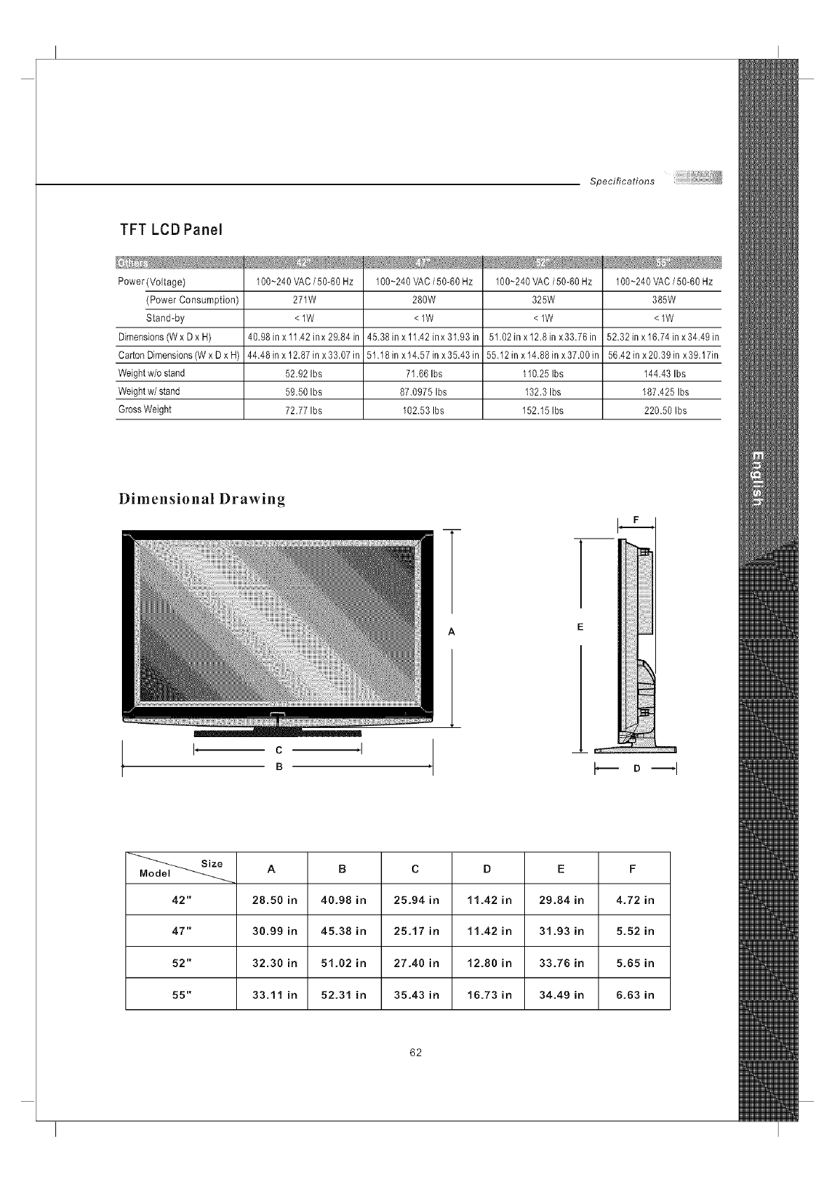
Specifications
TFT LCD Panel
Power (Voltage)
(Power Consumption)
Stand-by
Dimensions (W x D x H)
Carton Dimensions (W x D x H)
Weight w/o stand
Weight w/stand
Gross Weight
100~240 VAC /50-60 Hz
271W
<lW
40.98 in x 11.42 in x 29.84 in
44.48 in x 12.87 in x 33.07 in
52.92 Ibs
59.50 Ibs
72.77 Ibs
100~240 VAC /50-60 Hz
280W
<lW
45.38 in x 11.42 inx 31.93 in
51.18 in x 14.57 in x 35.43 in
71.66 Ibs
87.0975 Ibs
102.53 Ibs
100~240 VAC/50-60 Hz
325W
<lW
51.02 in x12.8in x33.76in
55.12 in x 14.88 in x 37.00 in
1I0.25 Ibs
132.3 Ibs
152.151bs
100~240 VAC /50-60 Hz
385W
<lW
52.32 in x 16.74 in x 34.49 in
56.42 in x20.39 in x39.17in
144.43 Ibs
187.425 Ibs
220.50 Ibs
Dimensional Drawing
I, c,I ,
B D --I
A B C D EF
42" 28.50 in 40.98 in 25.94 in 1!.42 in 29.84 in 4.72 in
47" 30.99 in 45.38 in 25.17 in 11.42 in 31.93 in 5.52 in
52" 32.30 in 5!.02 in 27.40 in 12.80 in 33.78 in 5.85 in
55" 33.11 in 52.31 in 35.43 in 16.73 in 34.49 in 6.83 in
62
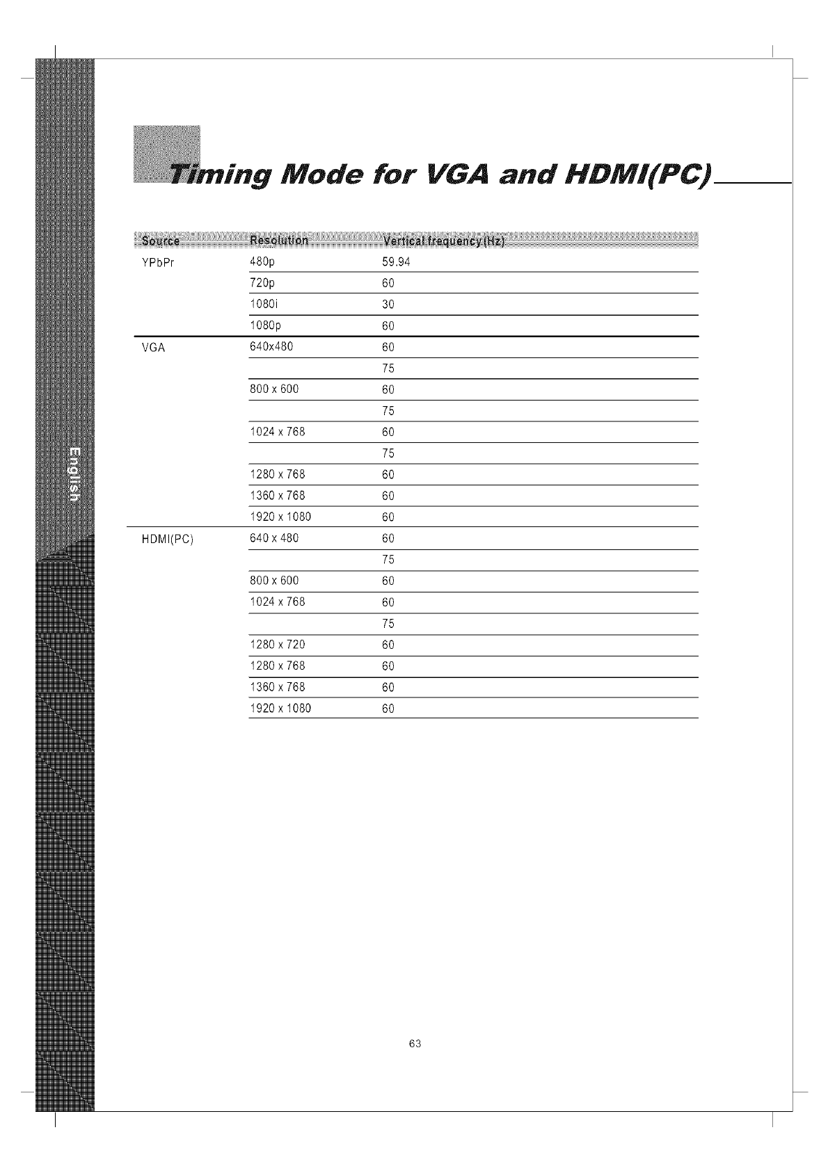
"Mode for VGA and HDMI(PC)
YPbPr 480p 59.94
720p 60
1080i 30
1080p 60
VGA 640x480 60
75
800x 600 60
75
1024 x 768 60
75
1280 x 768 60
1360 x 768 60
1920 x 1080 60
HDMI(PC) 640x 480 60
75
800x 600 60
1024 x 768 60
75
1280 x 720 60
1280 x 768 60
1360 x 768 60
1920 x 1080 60
63
Policy
SyntaxBrillian's D.O.A. Policy for LCD HDTVs for
Defective Pi×eJs on LCD PaneJs
(Applicable to the LCD IIDTV sold within USA & Canada only)
SyntaxBrillian LCD HDTVs are evaluated at a distance of approximately 50 centimeters
(approximately 20 inches) between the LCD panel and the eyes of the user at a
90 degrees viewing angle. All LCD panels have been tested to ensure they
comply with our factory standards. Our evaluation is based on the number of
defective pixets and the distance between any two defective pixels. Bright dots
are dots that appear bright and unchanged in size when a LCD HDTV screen
displays under a black pattern; dark dots are dots that appear dark and
unchanged in size when a LCD HDTV screen is displayed under pure red, green,
or blue patterns ("defective pixels"). Adjacent dots are dots located directly
nextto each other.
Customers are required to check their LCD panel immediately after purchase.
Toidentify defective pixels, the LCD panel should be examined under normat
operating conditions as mentioned above, preferably in its native display
resolution, and with a 90 degrees viewing angle.
ALCD HDTV will be considered dead on arrival (D.O.A.) with regardsto defective
pixels on the LCD panel when any one of the following criteria is met:
_, Atotat of 7 defective pixels including both bright dots and dark dots are
present (the typical 30" LCD Television screen has 1 million pixets), or
® 2 or more pairs of adjacent bright dots are present, or
_ 3 adjacent bright dots are present, or
® 3 adjacent dark dots are present.
tn view of customers' concerns about dead pixels, SyntaxBriltian would like to address
that defective pixets are not ultimately avoidable with the current LCD industry
standard panel manufacturing processes. We always strive to improve our
technology and minimize the chance of occurrence of defective pixets by
applying strict screening processes in our factory production processes.
However, SyntaxBrillian cannot guarantee that a return unit to our customers will be
100% free of defective pixels.
For questions, please call our tolt free service number in the USAat 888-Syntax-Briltian-8.
"At Synta×-Brillian Corporation, a satisfied customer is our
most important focus."
64
3:2 pull down - Process of converting 24 frames per second fitm to video by repeating one film frame
as three fields, then the next film frame as two fields,
1 1 1 2 2 111 2 2
4801-4801inesofdisptayevery 1/60ofa second image is displayed by interlace scanning, See
also Interlaced
480P - 480 lines of display every 1/60 of a second; image is displayed by progressive scanning, See
also Progressive,
720P - 720 lines of disptay every 1/60 of a second; image is displayed by progressive scanning, See
also Progressive,
10801 - 540 lines of display x 2 every 1/30 of a second; image is displayed by interlace scanning,
See also Interlaced
16;9 - Aspect ratio under Hi Def, and theater movie formats, Also known as widescreen; see Aspect
Ratio
4,3 - Aspect ratio under SDTV; see Aspect Ratio
Active Matrix TFT (Thin Film Transfer) -Atype of display technology where the three primary
colors are modulated, Results in better contrast ratios suitable for video,
Alarm- Feature on the Syntax-Brittian Otevia models, Allows the unit to power on from the stand by
mode,
Alarm Time-Time specified as to when the unit will power on, See Alarm,
Aspect Ratio - The ratio of an image according to the width and height of a picture,
ATSC - Advanced Television Systems Committee; international, non-profit organization that is
committed to developing standards for digital television,
Reference ; http ;//www,atsc,org
Bezel - Refers to the plastic or metal frame that acts like a shell around the LCD glass,
Backlight -Refers to the component, that lights up the LCD display,
Balance - Feature on the OSD for the Otevia models that adjust the left and right sound output from
the speakers,
Background - Feature on the OSD for the Otevia models, which allows the user to change the OSD
background, display to transparent or opaque,
Brightness-The measurement of color that is illuminated, Colors range from black to white,
CATV - Community Antenna Television (Cable Television)
Channel Favorite - Feature on the OSD for the Otevia models that allows the user to scroll through a
defined list of channels that the user sets up,
Channel Edit - Feature on the OSD for the Olevia models that allows the user add or delete a channel,
Channel Source - Feature on the OSD for the Olevia models that lets the user select the source of their
channels, SelectTV for antennae orCATVforcabtetetevision,
Channel Auto Scan - Feature on the OSD for the Olevia models that when initiated, wilt determine
which channels are available and which are not, Ifa desired channel is not accessible, you can add the
channel in manually, See Channel Edit,
Channel Fine Tune - Feature on the OSD for the Otevia models that enables the user to tune the channel
for better reception,
Chrama - (Chrominance) Refers to the color characteristics of a video signal,
CC - Closed Caption
65
Glossary
Color-The term refers to the amount of color present. This varies between each user, as each person
perceives colors differently.
Color Temperature- Feature on the OSD for the Olevia models that enables warm, normal or cool color
settings. Warm emphasizes red, cool emphasizes blue, and normal doesn't emphasize any of the primary
colors. This setting may affect each person individually depending on how color is perceived.
Comb Filter - A filtering system designed to removal unwanted artifacts by rejecting certain frequencies
while permitting others.
Component-Athree RCAtype input that uses high quality cables (one for brightness, and two for color),
Process increases bandwidth resulting in more color information to be carried to the TV producing a more
accurate picture.
Composite - Also known as CVBS, Technology that permits the combination of color information and
brightness under one wire. A single video signal that carries both brightness and color information are
contained in a single wire.
Contrast - Difference in luminance between the white and black colors.
CRT - Cathode Ray Tube.
DBI5-AIso referred to as VGA; SeeVGA
De-Interlace - Process of converting an interlaced video signal.
Display Area - The perimeter of the LCD giass the image is displayed on. See Video Resolution
Dual Link- See Single Link; Supports a maximum bandwidth of 2 x 165 MHz (1920 x 1080 @ 60 Hz, 1280 x
1024 @ 85 Hz).
DVI-DigitalVideolnterface Describes the technoiogy that is used to take fuil advantage of a signal when
paired with a high-end video card and flat panel displays
DVI-A - Digital Video Hi-Resolution Analog
DVI-D - Digital Video Interface Digital; Cable is used for direct connection from one digital source to the TV;
See DVl
DVH - Digital Video Interface Integrated; Cable that supports analog and digital signals; See DVl
DTV - Digital Television
Factory Default- Feature on the OSD for the Olevia models that resets all menu options to factory default.
F-Connector - The standard connector found on video equipments that coaxial cables connect to.
Fist-Panel Display - ultra thin displays, usually found in notebooks are now entering the TV appliances sector
as new technology enables wider/larger screens.
Frame-Acomplete picture that includes both even and odd lines. 30 video frames are present in 1 second.
Freeze- The Freeze button on the Otevia remote control lets you stop the image on your TV. When you Freeze
an image, you can write down what you see on-screen such as a telephone number, business address, or web
site. You can also look at a frozen image of a golf swing. And you still hear the program running in the
background, The frozen image stays on-screen indefinitely until you press Freeze again to go back to the
program. Freeze also works with PIP.
Gain - Describes the amplification level of a particular signal.
HDCP - High bandwidth Digital Content Protection
HDTV- 1.High Definition Television 2. Designates as the unit having a built inATSC tuner to decode High
Definition signals (720P/10801).
HD-Ready - A unit that supports the High Definition displays (720P/10801) with the help of a Set-Top Box.
Horizontal Resolution - Refers to the number of vertical black and white lines defined along a horizontal line.
IR - Infrared
Input-term used in the On Screen Display
66
Glossary
Interlaced - Images are the result of lines of data reassembled. Interlaced refers to the process
of an image's odd lines reassembled from top to bottom taking about 1/60 of a second, before
reassembling the even lines which resutts in a full picture. Antonym: Progressive
Language - Feature on the OSD for the Otevia models that enables the OSD to be read in different
languages.
LCD -Liquid Crystal Display
LCoS -Liquid Crystat on Silicon
LED -Light Emitting Diode
Luminance -refers to the brightness of an image.
Lux -1 Lux = 1 footcandle; measurement of brightness
Moire -A visual iItusion in which a succession of paraNet curved lines produces a pattern to the
naked eye, but does not reatty exist. Otherwise known as the moire effect.
NCTA -National Cable Television Association
Noise reduction -Feature on the OSD for the Otevia models that enables channels from the tuner
box to reduce noise displayed on the LCD unit.
NTSC -National Television systems Committee
OSD -On Screen Display; brought up by pressing the menu button on the TV or the Remote.
Over Scanning -An image displayed is larger than the display area
PAL -Phase Alternating Line
Parental Control - The ability to block access to specified content from an unsuitable audience.
PIP - Picture in Picture; feature that enabtes one source to be displayed on top of another source.
Pixel Resolution - Refers to the number of rows horizontal and vertical that produces the image.
PIP - Picture in Picture; Atlows an image to be displayed in front of another image.
Plug and Play - Describes the hardware or software that is installed and does not require any
configuration before using.
Progressive - An image or lines of data that is reassembled from top to bottom sequentially.
Antonym: Interlaced
RGB- Red, green &blue These primary colors provide the basis for many different colors.
Refresh Rate - Refers to the maximum number of frames that the monitor can display per second.
Usualty measured in hertz.
Saturation - The amount of a particular color present in an image.
SCART - An industry standard for interconnecting audio-video equipment developed by Peritet.
Usually associated with PAL video equipment.
SDTV - Standard Definition Television usualty in 480t/P format.
SECAI'4 - Sequential Color with Memory or Sequential Couleur Avec iV]emoire
Set-Top-Box - box that is capable of receiving and decoding digital transmissions (i.e. High
Definition Cable Box, Digital Cabte box).
Sharpness - Tries to artificially enhance the edges of a picture.
Single Link - supports a maximum bandwidth of 165 iV]Hz
(1920 x 1080 @ 60 Hz, 1280 x 1024 @ 85 Hz).
Split screen -Feature that places two images side by side.
1 2
67
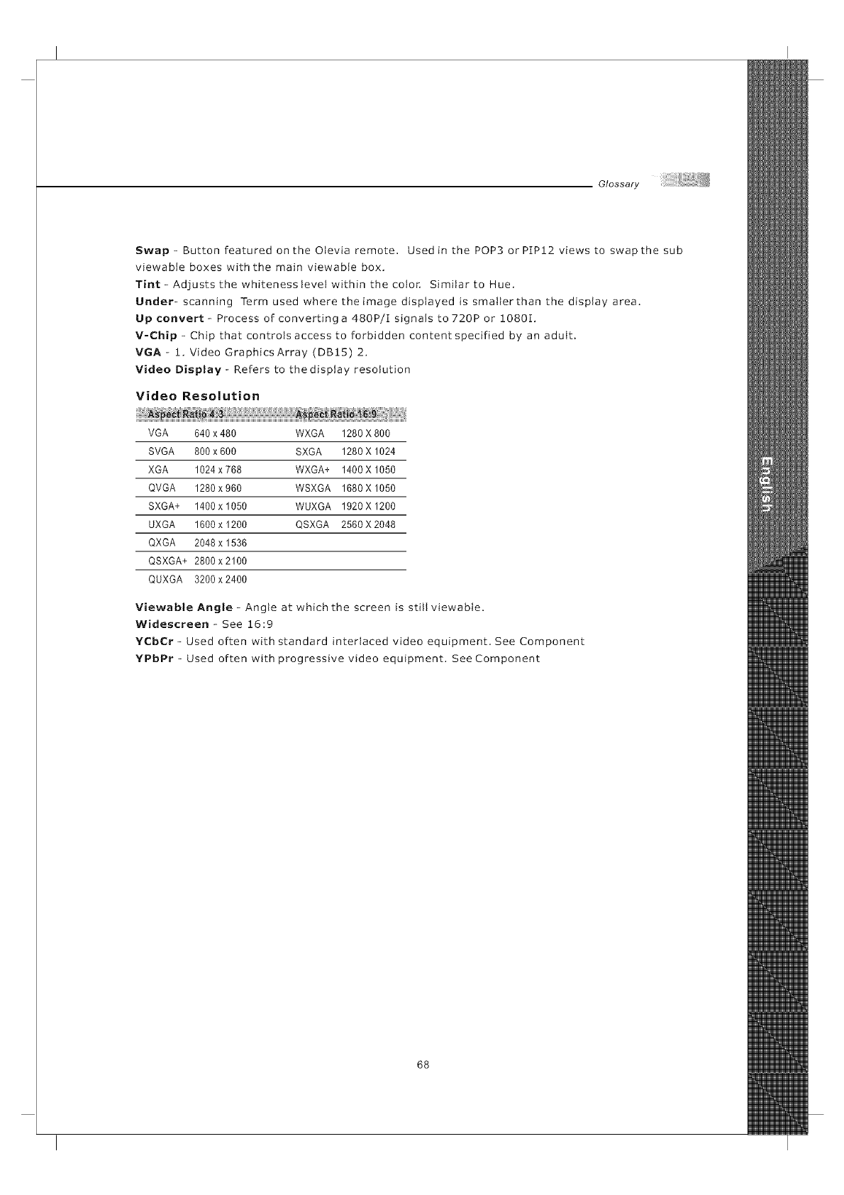
Glossary
Swap- Button featured on the Otevia remote. Used in the POP3 orPIP12 views to swap the sub
viewable boxes with the main viewable box.
Tint- Adjusts the whiteness tevetwithin the color, Similar to Hue.
Under- scanning Term used where the image displayed is smalterthan the display area.
Up convert - Process of converting a 480P/I signals to 720P or !080I,
V-Chip - Chip that controls access to forbWden content specified by an adult.
VGA - !, Video Graphics Array (DB15) 2,
Video Display- Refers to thedisplay resolution
Video Resolution
VGA 640 x 480 WXGA 1280 X 800
SVGA 800 x 600 SXGA 1280 X 1024
XGA 1024 x 768 WXGA+ 1400X 1050
QVGA 1280 x 960 WSXGA 1680 X 1050
SXGA+ 1400 x 1050 WUXGA 1920 X 1200
UXGA 1600 x 1200 QSXGA 2560X 2048
QXGA 2048 x 1536
QSXGA+ 2800x2100
QUXGA 3200 x 2400
Viewable Angle - Angle at which the screen is still viewabte.
Widescreen - See 16:9
YCbCr - Used often with standard interlaced video equipment, See Component
YPbPr - Used often with progressive video equipment. See Component
68
_LI_:::VIA
oJevia_com
2048Q EAST BUSINESS PARKWAY
MKO_UMO0179G000
SKU#: MD0-UM2TFHD
