Omega Research and Development 111 Security/Remote Control Transmitter User Manual MAX EDP Owner Paginated
Omega Research and Development Inc Security/Remote Control Transmitter MAX EDP Owner Paginated
User Manual

COPYRIGHT 2007: OMEGA RESEARCH & DEVELOPMENT, INC.
Omega
RS-210-DP
OPERATION MANUAL
Products manufactured and sold by OMEGA RESEARCH & DEVELOPMENT,
INC. (the "Company"), are warranted to be free from defects in materials and
workmanship under normal use. If a product sold by the Company proves to be
defective, the Company will repair or replace it free of charge within the first year
and thereafter all parts to be repaired will be free with only a nominal charge for
Omega's labor and return shipping, to the original owner during the lifetime of the
car in which it was originally installed.
All products for warranty repair must be sent postage prepaid to Omega
Research & Development, Inc., P.O. Box 508, Douglasville, Georgia 30133, or
send via UPS to: 981 N. Burnt Hickory Rd., Douglasville, Georgia 30134, with
bill of sale or other dated proof of purchase. This warranty is nontransferable and
does not apply to any product damaged by accident, physical or electrical misuse
or abuse, improper installation, alteration, any use contrary to its intended
function, unauthorized service, fire, flood, lightning, or other acts of God.
This warranty limits the Company's liability to the repair or replacement of
the product. The Company shall not be responsible for removal and/or reinstallation
charges, damage to or theft of the vehicle or its contents, or any incidental or
consequential damages caused by any failure or alleged failure of the product to
function properly. UNDER NO CIRCUMSTANCES SHOULD THIS
WARRANTY, OR THE PRODUCT COVERED BY IT, BE CONSTRUED
AS A GUARANTEE OR INSURANCE POLICY AGAINST LOSS. The
Company neither assumes nor authorizes any person or organization to make any
warranties or assume any liability in connection with the sale, installation, or use
of this product.
This device complies with F.C.C Rules part 15. Operation is subject to the
following two conditions: (1) This device may not cause harmful interference
and, (2) This device must accept any interference that may be received, including
interference that may cause undesired operation.
The manufacturer is not responsible for any radio TV interference caused by
unauthorized modifications to this equipment. Such modifications could void the
user’s authority to operate the equipment.
L I M I T E D L I F E T I M E W A R R A N T Y
Omega Research and Development, Inc.
P. O. Box 508
Douglasville, Georgia 30133
www.caralarm.com
07/08 MO-RS-210-DP REV0
This device complies with FCC Rules part 15. Operation is subject to the
following two conditions, (1) This device may not cause harmful inter-
ference and, (2) This device must accept any interference that may be
received, including interference that may cause undesired operation.
The manufacturer is not responsible for any radio or TV interference
caused by unauthorized modifications to this equipment. Such modifica-
tions could void the user's authority to operate the equipment.
Omega Research and Development, Inc. www.caralarm.com
Page - 2
Coin batteries used in the transmitter which is used to operate this
system may contain Perchlorate Material - special handling may apply.
See www.dtsc.ca.gov/hazardouswaste/perchlorate
Page - 15
Table of Contents
Introduction/System Overview ................................................ 3-4
Valet Switch Overview ................................................................ 3
Transmitter Overview................................................................... 4
Using the RS-210-DP System ................................................. 5
Unlocking The Doors ................................................................... 5
Remote Starting ............................................................................ 5
Using The Valet Switch .......................................................... 6
Valet Mode ................................................................................... 6
Pit-Stop Feature ............................................................................ 8
Other Remote Start Features ................................................... 7
Turbo Timer Feature .................................................................... 7
Status Light Functions ............................................................. 7-8
Transmitter Protection............................................................. 8
How to Program Transmitters ................................................. 9
How to Program Features........................................................ 9-10
User Programmable Features .................................................. 10-11
Installer Programmable Features............................................. 11-14
Complete Programmable Features Matrix .............................. 15
Limited Lifetime Warranty .............................................. Back Cover
- IMPORTANT -
The RS-210-DP has many programmable features which can offer
more operations than those described in the basic system instruc-
tions. Mostly, these extra features and operations are configured
at the time of installation. Please read the sections of this manual
which explain programmable features, and consult your installer
for specifics on how your system is configured, and for installation
options which can be added to system after installation.
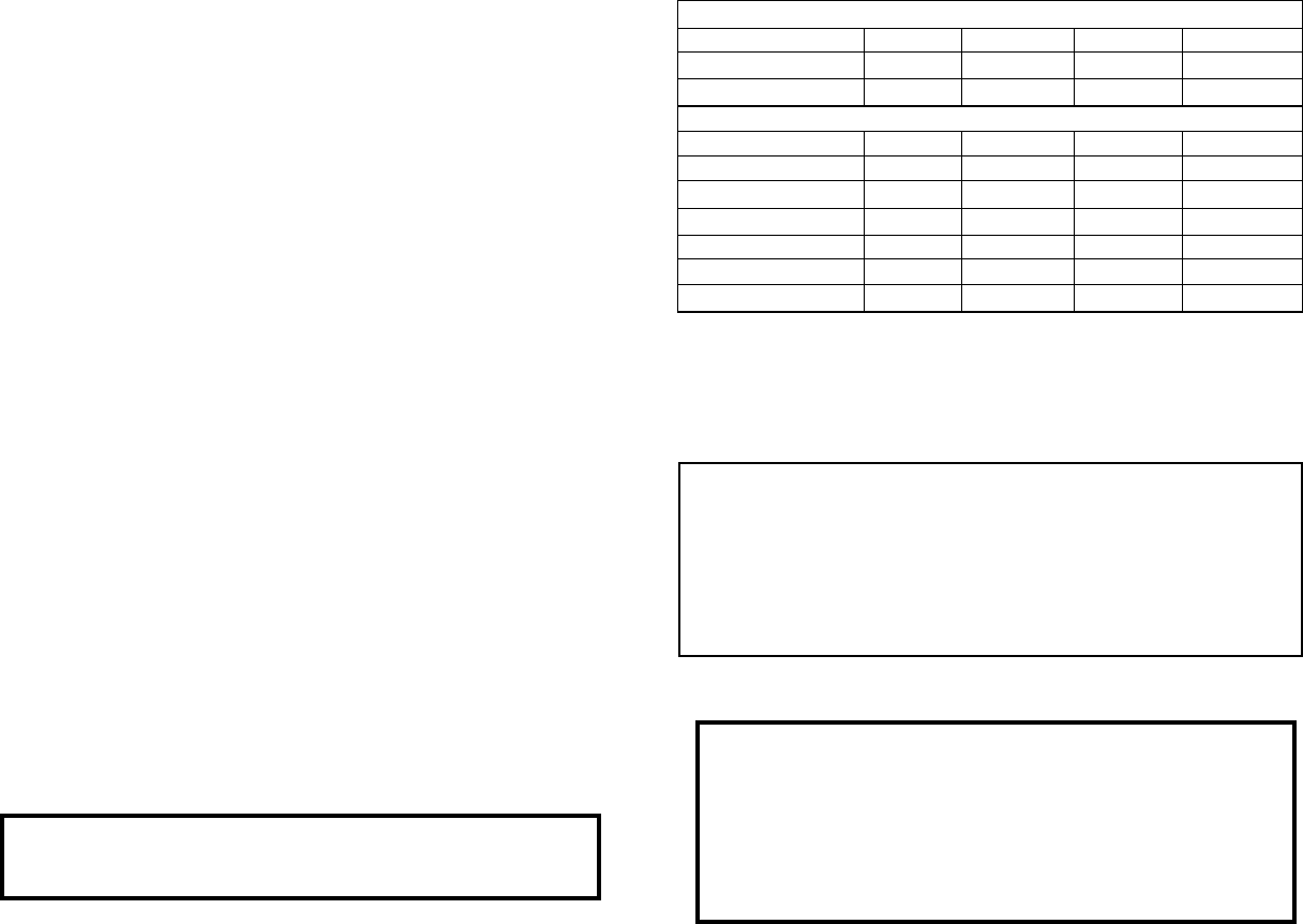
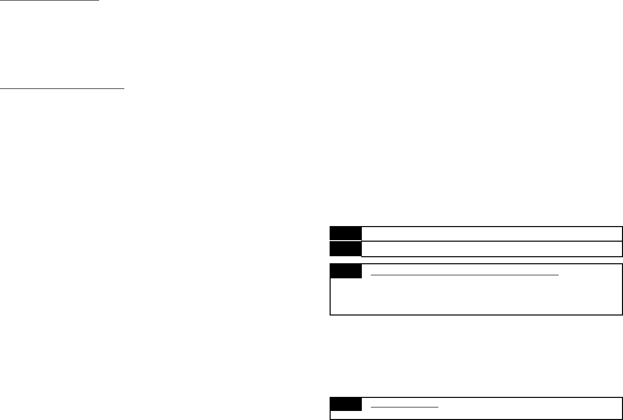
Complete Programmable Features Matrix
USER Features Ignition on, off, then press Valet Switch 5 times (BLUE Status Light).
# Feature Brake Pedal x 1 Brake Pedal x 2 Brake Pedal x 3 Brake Pedal x 4
1 Remote Start Run Time 10 Min. 5 min. 15 min. 20 min.
2 Steady/Flash Lights Rem. Start Steady Flashing
INSTALLER Features Ignition on, off, then press Valet Switch 10 times (BLUE Status Light).
1 Remote Start Activation Pulses 1 2 3 4
2 “Tach Wire” or “Tachless “ Tachless Tach Data Tach
3 Gasoline or Diesel Engine Gasoline Diesel
4 Sat. Port Green Wire Function Starter Pulse After Start Pulse After Stop Accessory Output
5 Ext. Starter Cranking Time .7 (minimum) 1.25 1.75 2.5 (maximum)
6 Unlock Functions .8 second 3 Seconds Double Unlock N/A
7 Turbo Timer OFF 1 min. 2 min. 3 min.
Page - 3Page - 14
Welcome to the convenience which is offered by your RS-210-DP
keyless entry & remote start system. The RS-210-DP is designed and
manufactured by Omega Research and Development, a world leader in
vehicle convenience and security since 1975. Your system offers easy,
carefree operation, and the modular design allows its many impressive
features to be customized to suit your needs. Omega systems are designed
for professional installation, and are available only through new car retail
outlets and selected mobile electronics specialist dealers.
Please note that this guide is written to reflect:
- That a power doorlock interface is installed with your system
(the RS-210-DP also operates your power unlock function). The type
of interface may vary from one vehicle to the other, and in some
cases may involve optional components.
- That the Programmable Features are in the default settings;
the operations of these features are also explained.
Your RS-210-DP system has three principal user components: the Blue
LED Status Light, the Valet Switch, and the Remote Transmitter.
Introduction
The Valet Switch is used to access Valet Mode, which allows the
operator to suspend the remote start functions for as long as desired. The
Valet Switch is also used when programming remote transmitters and
system features. See “Using the Valet Switch” on page 6.
The Blue LED Status Light informs you at a glance which of the
different conditions the system is in. Specific operations of this light are
described on pages 7-8.
Transmitters are used to operate the RS-210-DP. Each system is
capable of being operated by up to four different remote Transmitters. The
remote transmitter has one push-button switch, which is labeled with an
icon as to indicate its primary function.
Feature #7 Turbo Timer
Factory Default Setting Off
(press brake pedal 1x to program)
Options:
Run 1 Minute (press brake pedal 2x to program)
Run 2 Minutes (press brake pedal 3x to program)
Run 3 Minutes (press brake pedal 4x to program)
This feature when turned on configures the RS-210-DP to automatically keep the
engine running briefly after it is turned off. This operation is designed specifically
for vehicles having turbocharged engines (the user may temporarily bypass the
feature if desired).
This feature should only be programmed by the installer, and the operation of
this feature depends on the correct connection of the safety wire to the vehicle’s
parking brake. Please refer to the “Black/White wire” in the installation manual for
the proper connection of this important wire.
• The second setting (programmed by pressing the brake 2x ) changes the
unlock output to be a longer 3 second pulse output. This is for certain
vehicles which require a longer output pulse from the system’s control unit;
typically cars having vacuum pump systems, although the longer setting is also
more suitable in some newer vehicles.
• Some newer vehicles require a double pulse output to remotely unlock the doors
and/or to disarm a factory-equipped security system, which is what the Double
Pulse Unlock setting provides (it is programmed by pressing the brake 3x ).
Feature #6 Unlocking Functions
Factory Default Setting 0.8 Second Unlock Output
(press brake pedal 1x to program)
Options:
3 Second Unlock Output (press brake pedal 2x to program)
Double Pulse Unlock Output (press brake pedal 3x to program)
This single feature gives the installer several needed options, to match the RS-210-
DP’s doorlocking outputs to suite different vehicle requirements.
• The first setting (programmed by pressing the brake 1x) has the system
produce the unlock output as 0.8 second in duration. This is the
most common form of output needed, which interfaces most vehicles.
duration of the starter output’s for the 1st start attempt. If the engine doesn’t start
on the first attempt, the system will retry up to 3 more times. With each attempt, the
output will be extended by 0.2 seconds. There are four different base starter output
settings. While the default-set minimum is sufficient for most vehicles; the
Extended Starter Cranking Time can be used for difficult-to-start engines. This
feature should only be programmed by the installer.
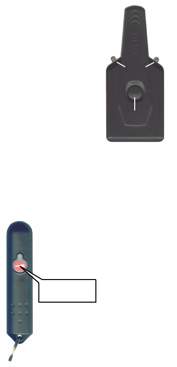
The Window Unit With Status Light & Valet Switch
One of the components, typically mounted on the windshield, is the
Window Unit module which contains the Status Lights and the Valet
Switch. The window unit also receives communications from the system’s
remote transmitters.
Page - 4 Page - 13
Valet
Switch
Status
Light
• The Valet Switch is used in the procedure of programming operational
features and also for encoding transmitters to the system. A complete
description of the Valet Switch and its operations is on page 6.
The Blue Status Lights report the operational status
of the system at all times, and also serves as a visual
deterrent to break-ins and theft. Specific description
of the Status Light operation may be found on pages
7-8.
The Valet Switch has three main functions:
• The Valet Switch can be used to turn off the
remote engine starting functions of the system placing
it in “Remote Start Valet Mode”.
The Transmitter & Basic Functions
“start” / “unlock”
button
Transmitter part number:
111-03 one button, long-range transmitter
Transmitter battery replacement:
Remove the small screw from the
lower back case, and separate the
transmitter case halves. Replace the
27A (or MN27 battery) battery and
reassemble the transmitter. Feature #5 Extended Starter Cranking Time
Factory Default Setting Minimum (.7 Second)
(press brake pedal 1x to program)
Options:
Medium Lo (1.25 Second) (press brake pedal 2x to program)
Medium Hi (1.75 Second) (press brake pedal 3x to program)
Maximum (2.5 Second) (press brake pedal 4x to program)
Extended Starter Cranking Time operates in conjunction with the feature #2’s
“Tachless” setting. When the system is set for “Tachless”, this feature sets the
This feature changes the operation of the Green wire (negative) on the satellite relay
port. This gives you the flexibility to accomodate certain vehicles that require any
out-of-the-ordinary pulses or remote start timing.
• The first setting operates as a secondary START output. This will have the same
pulse timing as the large Violet wire on the main harness.
• The second setting will give a 0.8 second pulse immediately after the large
Violet wire’s output stops.
• The third setting will give a 0.8 second pulse immediately after the remote start
shuts down by any means.
• The fourth setting operates as a secondary ACCESSORY output. This will have
the same operation as the large Orange wire on the main harness. This fea-
ture should only be programmed by the installer.
Feature #3 Gasoline Or Diesel Engine
Factory Default Setting Gasoline (press brake pedal 1x to program)
Option: Diesel (press brake pedal 2x to program)
This feature changes the system's timing of the ignition and starter output sequence
for remotely starting vehicles with gas or diesel engines. When set for gasonline, the
starter output will occur 3 seconds after the ignitions turn on. Also, when the system
is in “Tachless” mode, the engine running status will be determined 10 seconds after
cranking. When set for diesel, the starter output will occur 20 seconds after the
ignitions turn on to allow for glow plug warming. Also, when the system is running
in “Tachless” mode, the engine running status will be determined 40 seconds after
cranking. This allows the vehicle battery(s) to recharge properly and show normal
voltage levels due to the heavy drain diesel engines have on the electrical system
during cranking. This feature should only be programmed by the installer.
Feature #4 Satellite Relay Port Green Wire Function:
Factory Default Setting Starter (press brake pedal 1x to program)
Options:
Pulse After Engine Start (press brake pedal 2x to program)
Pulse After Engine Stop (press brake pedal 3x to program)
Accessory (press brake pedal 4x to program)
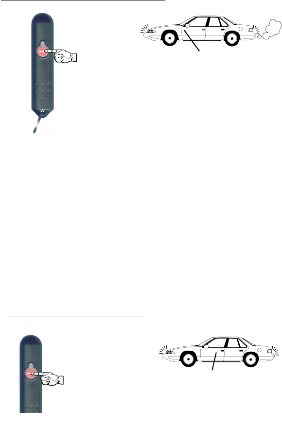
”start”/”unlock” button (red)
• Pressing & releasing the “start” button twice within 5 seconds will
activate the remote start feature. Pressing it twice again, during remote
start, will stop the engine.
• Pressing the “start” button for three seconds will activate the “unlock”
output (for vehicles that disable the factory keyless entry while the
engine is runnning).
Page - 5Page - 12
Using The RS-210-DP System
THE PARKING
LIGHTS WILL TURN
ON
THE ENGINE WILL CRANK
To Activate/Deactivate Remote Start:
Press & Release the transmitter “start” button twice
•The lights will turn back on and remain on while the system is control-
ling the engine. The status light will then continue to flash slowly.
•If the engine stalls, the system will make 3 more attempts to restart it.
•The parking lights will turn on and the Status Light
will flash fast to confirm that starting has begun.
•The sytem will then turn on the ignition circuit.
•Within a few seconds the lights will turn off and the
starter will engage.
•The engine will start, run, and the starter will be
disengaged.
Upon entering the vehicle place the ignition key in the switch and turn it
to the "On" position, pressing the brake pedal will deactivate the remote
start operation. Do not turn the key to the "Start" position!
If you decide not to drive your car after remote starting, you can simply
press & release the “start” button again to deactivate the remote start.
Otherwise, the system will “time-out” and turn off automatically after 10
minutes. NOTE: If there is no response when attempting to remote start
(and the system is not in valet mode), the system might be indicating that
a safety circuit is violated. This could mean that the hood is open, the gear
selector is not in park, or that the brake pedal is being pressed. Check
these safety circuits and retry.
When you leave your vehicle after driving, simply set the climate con-
trols for what you would like to have operating upon remote starting - the
heater, defroster or air conditioning.
Feature #2 “Tach Wire” , “Tachless”, or “Data Tach”
Starter Operation
Factory Default Setting Tachless (press brake pedal 1x to program)
Options: Tach Wire (press brake pedal 2x to program)
Data Tach (press brake pedal 3x to program)
This feature selects the RS-210-DP processor’s method of determining the status of
the engine running during remote start operation. As explained in feature 5’s
description, “Tachless” mode has an associated base starter output time duration.
However, if the voltage fluctuation is detectable, the processor adjusts the starter
output time accordingly. When this feature is set for “Tach Wire” operation, the
base starter output increases to a maximum of 3 seconds, but the processor adjusts
the actual starter engagement time accordingly. Connecting and use of the “Tach
Wire” is the most reliable form of engine running information input, and its use is
recommended. Important: Before this feature is programmed, please refer to the
“Violet/White wire” section of the installation manual for proper wiring connec-
tion, and the Tach Learning Procedure. The “Data Tach” setting operates just like
the “Tach Wire” setting except it takes its reading from the D2D data port. Use of
this setting is determined by whether or not this feature is provided by the Databus
Interface module. If so, the Violet/White wire is not needed nor is the Tach Learning
Procedure Required. This feature should only be programmed by the installer.
Feature #1 Remote Start Activation Pulses
Factory Default Setting:
1 pulse (press brake pedal 1x to program)
Options:
2 pulses (press brake pedal 2x to program)
3 pulses (press brake pedal 3x to program)
4 pulses (press brake pedal 4x to program)
This feature allows you to choose the number of pulses required on the White/Blue
activation wire to activate the remote start feature. This allows you to activate the
remote start with external devices. For example, you can connect this wire to a
factory installed keyless entry system. You can repurpose the factory lock button so
that multiple presses will activate the remote start. With any of the optional settings,
each 2nd, 3rd, or 4th pulse must occur within a 5 second window of the previous
pulse. This feature should only be programmed by the installer.
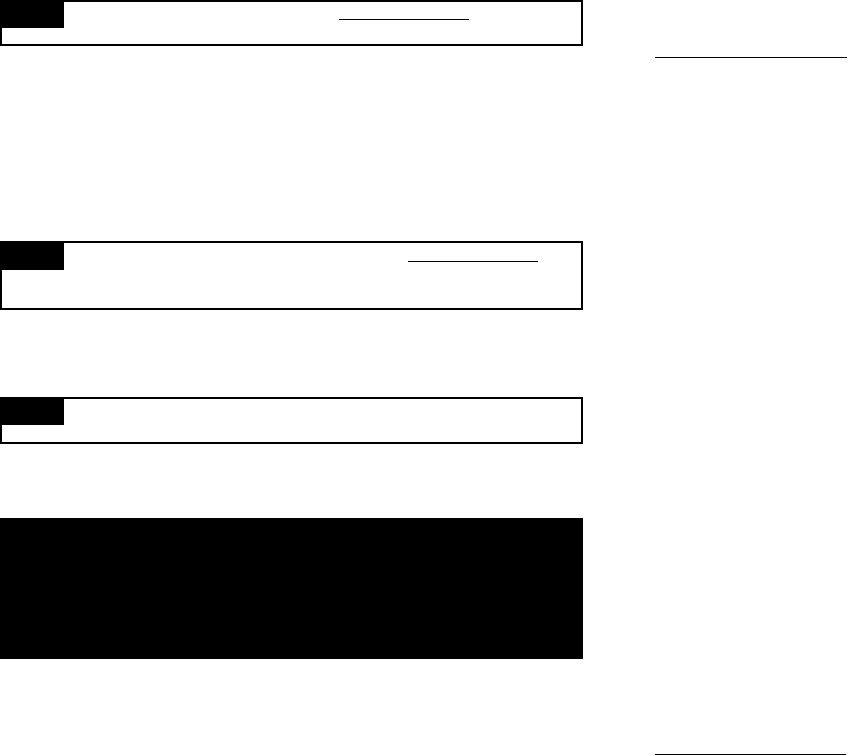
THE PARKING
LIGHTS WILL FLASH
TWICE THEN TURN
ON FOR 30 SECONDS
THE DOORS WILL UNLOCK
To Unlock the Vehicle's Doors:
Press & Hold the transmitter START button for 3 seconds
• The parking lights flash twice then stay on for 30
seconds to confirm unlocking. The Status Light will turn
off to indicate that the system is in an UNLOCKED state.

Page - 6 Page - 11
The Installer Programmable Features
The second group of features, the Installer Programmable Features, are accessed as
the second level of features’ programming, which is pressing the Valet Switch 10
times instead of 5 times when entering Programming Mode (page 9). Caution:
These features have a critical affect upon the system’s operations, and in many
cases, also upon the system’s wiring connections. These features should
NEVER be changed, except by the installer or other qualified professional. This
booklet should be consulted for the proper wiring connections, as associated with
these programmable features.
Feature #1 Remote Start Run Time
Factory Default Setting 10 Minutes (press brake pedal 1x to program)
Options:
5 Minutes (press brake pedal 2x to program)
15 Minutes (press brake pedal 3x to program)
20 Minutes (press brake pedal 4x to program)
This feature sets the period of time that the engine will run after being remotely
started. If the engine is not stopped by controller/transmitter command or a safety
circuit violation, the engine will automatically stop upon the expiration of the
selected time period. Caution: The remote engine starting feature should
NEVER be used when the vehicle is parked in an enclosed structure or garage.
Feature #2 Steady/Flashing Lights During Remote Start
Factory Default Setting Steady (press brake pedal 1x to program)
Option: Flashing (press brake pedal 2x to program)
This Feature configures the operation of the vehicle’s parking lights during the
remote start operation. The default setting turns on the parking lights during remote
start; the other setting flashes the parking lights on and off during remote start.
Valet Mode
The system may be placed into a “valet mode” which prevents the
remote start feature from being activated. It also disables confirmation
chirps when unlocking the doors. Valet Mode should always be used when
you do not wish for remote starting to be operated, such as when you have
your vehicle serviced.
The Valet Switch, is used to engage Valet Mode:
•With the system in an unlocked state, press and hold the Valet Switch
for 3 seconds; the Status Light will light steady, to indicate Valet Mode, and
stay illuminated continuously while the system is in Valet Mode. The lights
will flash twice.
Once in Valet Mode, an attempt to remote start will result in no response
from the system. Keep this in mind if remote start stops functioning. The
system may have accidentally been placed in valet mode.
•To turn off Valet Mode, simply press & release the Valet Switch once.
The Status Light will turn off.
Using The Valet Switch
Pit-Stop Feature
This feature allows you to leave your vehicle and keep the engine run-
ning for quick errands. To use this feature, have the engine running nor-
mally from the ignition switch, have the gear selector in “park”, and your
foot off of the brake pedal. Press the Valet Switch twice; the parking lights
will illuminate; then turn the ignition off. The engine will remain running for
the programmed run time, or it will turn off if another transmitter signal is
received, a safety circuit is violated, or if the Valet Switch is pressed.
Use the step-by-step instructions on page 9 to change any of the Installer
Programmable Features, along with the feature’s option choices and related
programming controller/transmitter button assignment found in the following
individual feature descriptions.
Page - 7Page - 10
Other Remote Start Features
Turbo Timer Feature
It is typically recommended that vehicles equipped with turbocharged
engines allow the engine to idle for a few minutes before turning it off.
When this Installer Programmable Feature is programmed on, the RS-
210-DP will automatically keep the engine running as follows:
• With the engine running, hold the brake pedal and engage the parking
brake. When the brake pedal is released, the RS-210-DP will keep the
engine running for the selected time, and then automatically turn it off.
Step 7 Allow 10 seconds to pass without performing any programming
actions, or turn the vehicle’s ignition on.
• The Status Light & parking lights will turn off.
Change the Feature:
Step 5 After accessing the desired feature, within 10 seconds Press &
Release the brake pedal equal to the option desired.
• Pressing the brake pedal once typically turns the feature on; or sets the
feature’s first option. The Status Light and the parking lights will
flash once when this option is chosed.
• Pressing brake pedal twice also typically turns the feature off; or,
sets the feature’s second option. The Status Light and the parking lights will
flash twice.
• Many features have third, and even fourth setting options. Pressing the brake
pedal 3 or 4 times will select these options. Status Light & parking lights
flash three or four times respectively.
To Access and Change further Features:
Step 6 If there are more features to be programmed, within 10 seconds of
the previous action Press & Release the Valet Switch the same
number of times as the next desired feature’s number.
• Again the Status Light and parking lights will flash as many times as the Valet
Switch was pressed to indicate the new feature number which is now accessed.
Then press the brake pedal as described in Step 5 to change the newly
accessed feature as desired.
The turbo timer feature must be programmed by the installer, and turn-
ing it on offers three run time choices- 1, 2, or 3 minutes. The system may
be locked while the engine is running. Turbo Timer can be prevented from
engaging, or “bypassed” if desired, by turning the engine off first and then
engaging the parking brake, or if it’s already engaged simply step on the
brake pedal to turn the running engine off.
The Status Light
The Status Light helps to visually confirms the status of the system and
provides a high level of visual deterrence. The Status Light is located in the
window mount receiver unit.
Normal System Status
2) On Constant = The system is in the Valet Mode, with the remote starter
system disabled.
1) Off = The system is unlocked and the remote starter system is off, but
in standby mode.
The User Programmable Features
- SEE PAGE 9 FOR PROGRAMMING INSTRUCTIONS -
Each of the Programmable Features is described in detail on the following
pages. The User Programmable Features are described as this first group,
and the Installer Programmable Features as a second group. Installer
Programmable Features should only be used by the original or other
qualified installer, AND individual Installer Features should only be used
with the correct wiring connections.
This group of User Programmable Features are all accessed as a group in the first
level of features’ programming. These features have a direct affect upon the
system’s operations, so the programming and operation of each are described.
Use the step-by-step instructions on page 9, and the complete features matrix on
page 15, to change any of the programmable features. Each feature, the option
choices and related programming transmitter button assignment are described in
detail in the following pages.
Page - 8 Page - 9
5) Flashing Slow (after sending the remote start command) = The engine
is running via the remote starting system.
Starting System Status
The Status Light also indicates the remote start status:
4) Off = The remote starter system is off and in standby mode.
6) Flashing Fast (after starting the remote start sequence) = A remote start
command has been received, and the system is in the process of
starting the engine.
Remote Starting Diagnostics
Whenever the system is placed into Valet Mode, the Status Light
illuminates solid. However, when this first occurs, the Status Light will flash
1 to 6 flashes before resuming solid illumination. This indicates why the
engine stopped running from the last previous remote starting attempt.
7) 1 Flash = Programmed run time expired.
8) 2 Flashes = Brake was pressed or hood opened.
9) 3 Flashes = Engine stalled or bad tach signal.
10) 4 Flashes = Received transmitter command to stop.
11) 5 Flashes = Gear selector removed from “park”.
12) 6 FLashes = Low voltage.
Automatic Transmitter VerificationTM (ATV) shows the total number of
transmitters which can operate the system, by flashing the Status Light with
this number for 10 seconds every time that the ignition key is turned on.
The Omega RS-210-DP features several security safeguards in one of
the most vulnerable areas of any remotely controlled system.
Transmitter Protection
Code JumpingTM It is quite easy, with the proper equipment, to record an
alarm or keyless entry system’s transmitter signal, and simply play the
captured signal back to the system to defeat it. The RS-210-DP’s Code
Jumping renders such “code grabbing” devices useless by randomly
changing each signal that the transmitter sends.
Step 1 Have all transmitters which are to operate the system at hand.
Then, turn the ignition “on”.
Step 3 Press the “start” button on each remaining transmitter one at a
time. The system will turn off the lights once to confirm that each was
learned. If a code is not received within a 10 second period, the
learning process will automatically terminate, as indicated by the
lights turning off.
Step 2 Within 5 seconds of turning on the ignition, press the Valet Switch
5 times. The parking & status lights will illuminate, confirming that
for the next 10 seconds the system is ready to learn a transmitter
code. Simply press and release the “start” button. When the first
code is learned, existing stored codes will be erased.
Transmitter Programming:
The RS-210-DP system is capable of being operated by as many as four
transmitters. Additional transmitters must be programmed to the system in
order to operate it (the originals, were programmed at the factory).
How to Program Transmitters
Programming Features
Step 2 Turn the ignition off.
Step 1 Turn the vehicles’s ignition on.
Access a Feature:
Step 4 Within 10 seconds, Press & Release the Valet Switch the same num-
ber of times as the desired feature’s number.
•The Status Light & parking lights will flash equal to the number of the
selected feature. The Status Light will continue to flash in the same manner
with a brief pause between each flashing sequence.
•The Status Light & parking lights will turn on to confirm that the system has
entered Programing Mode.
•In the case of accessing the Installer Mode, the lights will turn on at the fifth
valet switch press, immediately turn off at the sixth valet press, and then turn
on again at the tenth valet switch press.
•In either Programming Mode, if 10 seconds of no programming activity
occurs, the system will exit Programming Mode.
5 times for User Programming (Solid Status Light)
OR
10 times for Installer Programming (Solid Status Light)
Step 3 Within 5 seconds, Press & Release the Valet Switchch either:
Page - 16 Page - 17
Note: This equipment has been tested and found to comply with the limits
for a Class B digital device, pursuant to part 15 of the FCC Rules. These
limits are designed to provide reasonable protection against harmful
interference in a residential installation. This equipment generates,
uses and can radiate radio frequency energy and, if not installed and
used in accordance with the instructions, may cause harmful
interference to radio communications. However, there is no guarantee
that interference will not occur in a particular installation.
If this equipment does cause harmful interference to radio or television
reception, which can be determined by turning the equipment off and on,
the user is encouraged to try to correct the interference by one or
more of the following measures:
—Reorient or relocate the receiving antenna.
—Increase the separation between the equipment and receiver.
—Connect the equipment into an outlet on a circuit different from that
to which the receiver is connected.
—Consult the dealer or an experienced radio/TV technician for help.
Information to user
The users manual or instruction manual for an intentional or unintentional
radiator shall caution the user that changes or modifications not expressly
approved by the party responsible for compliance could void the user's
authority to operate the equipment. In cases where the manual is provided
only in a form other than paper, such as on a computer disk or over
the Internet, the information required by this section may be included in the
manual in that alternative form, provided the user can reasonably be
expected to have the capability to access information in that form.