Omni Pro Software C3I173M C3I Wireless Gateway User Manual
Omni-Pro Software, Inc. C3I Wireless Gateway
user manual

C3IWirelessGateway
Installation Manual
Omni-Pro Software, Inc.
23608 458th Avenue
Madison, SD 57042
C3IWireless Gateway Installation Manual
605-270-2285

General Hardware Functionality
•The C3IWireless Gateway is a load control and remote
meter readin
g
device suitable for munici
p
al utilit
y
use.
gpy
•NOTE: The screw terminals on the circuit board are to be
tightened carefully or damage to the board could result.
•C3IWireless Standard:
•4 Pulse/Status Inputs
•
3 Pilot Relays
3
Pilot
Relays
•2 Meter Encoder Inputs
•RS485 Serial Port Metering Inputs
•Integrated VHF Radio Transceiver
•Power Supply
GE
I210 C i ti M d l
•
GE
-
I210
+
C
ommun
i
ca
ti
on
M
o
d
u
l
es
•Plug In Type 12 Volt Regulated DC
•Other 12 Volt Regulated DC supplies (In Line)
•Metering Interfaces
•GE I210+ Communication Modules
•GE KV2C Communication Modules
•Transparent Technologies Wireless Meters
•Electronic Meter KYZ Pulse Initiators
•Water/Gas Meter Pulse Initiators
•
Absolute Digital Encoder Interfaces
•
Absolute
Digital
Encoder
Interfaces

C3IGateway Operation
• The C3IWireless Gateway product line sends data to a master communications
station via a digipeater network Each unit has an individual identification number
station
via
a
digipeater
network
.
Each
unit
has
an
individual
identification
number
.
When data is needed from a unit, the computer polls the unit through the assigned
digipeater path.
• A digipeater is a unit that retransmits packet data. For example, if data is needed
from unit ID 500, and the closest digipeater that has been assigned is unit ID 20, the
transmissions will route as follows:
transmissions
will
route
as
follows:
• POLL MESSAGE FROM MASTER TO DIGIPEATER ID 20
• POLL MESSAGE FROM DIGIPEATER ID 20 TO UNIT ID 500
• RESPONSE MESSAGE FROM UNIT ID 500 TO DIGIPEATER ID 20
•
RESPONSE MESSAGE FROM DIGIPEATER ID 20 TO MASTER COMPUTER
•
RESPONSE
MESSAGE
FROM
DIGIPEATER
ID
20
TO
MASTER
COMPUTER
• Note: If the communications path fails, the computer will retry the route up to the
specified number of retries before trying the alternate digipeater path.
• An alternate digipeater path would be the next best routing path determined by
terrain, buildin
g
, and distance issues. This alternate
p
ath can be entered into
gp
software so the system can automatically switch to it in case the primary digipeater
path fails.
• If the unit fails to communicate after both digipeater paths have been tried the
appropriate number of times, the unit ID will be added to the error log.

TROUBLESHOOTING COMMUNICATIONS
• If a unit fails to report, the following might solve the problem:
•FROM MASTER
• Insure master is up and running, check to see if other units are reporting. If no units at all are reporting, reset
master station computer. If resetting master station computer has no effect, reset master radio control unit. If
no units communicate after this, an equipment failure is possible. We will use your C3IConfig PDA as a
master and attach it to the master radio control unit to check status.
• If some units will report, then:
• Make sure di
g
i
p
eaters are communicatin
g
b
y
p
ollin
g
them manuall
y
.
gp g yp g y
• If digipeater doesn’t report, reset it and insure unit control board and radio equipment is powered. If it still will
not report, then connect C3IConfig PDA to check status.
• If the digipeater is communicating with the master, try polling the unit with a different digipeater. It is possible
that the unit is too far away or has an obstruction reducing the signal strength, etc. The next step would be to
try polling it with a path that includes a neighboring gateway ID that responds correctly.
•FR
O
M
G
ATEWAY
U
NIT
OG U
• To determine if a gateway has failed, or if the communications path is not reliable, attach the configuration
PDA.
• Check to see if configuration ID matches label’s ID number.
• Check to see if utility/segment ID matches system assignment.
• Attempt to poll the nearest digipeaters with the PDA and see if data returns.
Document the digipeaters that work reliably with that unit
–
Document
the
digipeaters
that
work
reliably
with
that
unit
• If the gateway will not communicate with the PDA, check to make sure gateway is powered up. Next attempt
to reset the gateway by un-powering then power back up. If unit still fails, try a different gateway and consult
Omni-Pro.

C3IWireless Gateway Functionality
• Each gateway returns the following information when polled:
•Normal Readin
g
Poll
g
• 4 Input Counters (Actual Meter Reading Accumulators)
– Up to Two GE electric meters
– Up to Two Absolute Digital Encoder Meters
• 4 Status Inputs
• 3 Relay Status
3R l O ti C t
•
3
R
e
l
ay
O
pera
ti
on
C
oun
t
ers
• 4 Demand Accumulators
• Meter Diagnostics and Voltage
• Remote Disconnect Status (Where Available With GE I210+RD Meter)
•Demand Poll (C & I Units Only)
•
2 Input Counters
•
2
Input
Counters
• 4 Status Inputs
• 3 Relay Status
• 3 Relay Operation Counters
• Monthly High KV2C Demand & Reset
•Load Mana
g
ement Rela
y
Address Messa
g
in
g
gy gg
• Each relay on the gateway can be assigned a group control address and cold load pickup settings. These
parameters are returned to the master station in a reply message in order to verify that the gateway is properly
configured.

C3IWireless Gateway Installation
•Attach Gateway Enclosure
•
The C3IWireless Gateway features three mounting
The
C3IWireless
Gateway
features
three
mounting
tabs to be used for mounting. Use lag screws or
bolts appropriate to the structure the device is
mounted to. The C3IWireless Gateway should be
mounted close to the electric meter.
• The device must be mounted with the access holes
facing
DOWN See Picture
The condensation
facing
DOWN
.
See
Picture
.
The
condensation
drain hole is located on the bottom of enclosure.
• Screw Terminals are labeled for power, pulse-status
inputs, and relays 1-3.
•
Power
-
Status LED will stay solid GREEN with
Power
Status
LED
will
stay
solid
GREEN
with
occasional flash when the assigned metering
devices are successfully communicating with the
C3IWireless Gateway.
• If Transparent Technologies Wireless devices are
used, Status LED should be ON for 4 seconds, then
OFF for 2 seconds when all metering inputs are
OFF
for
2
seconds
when
all
metering
inputs
are
valid.
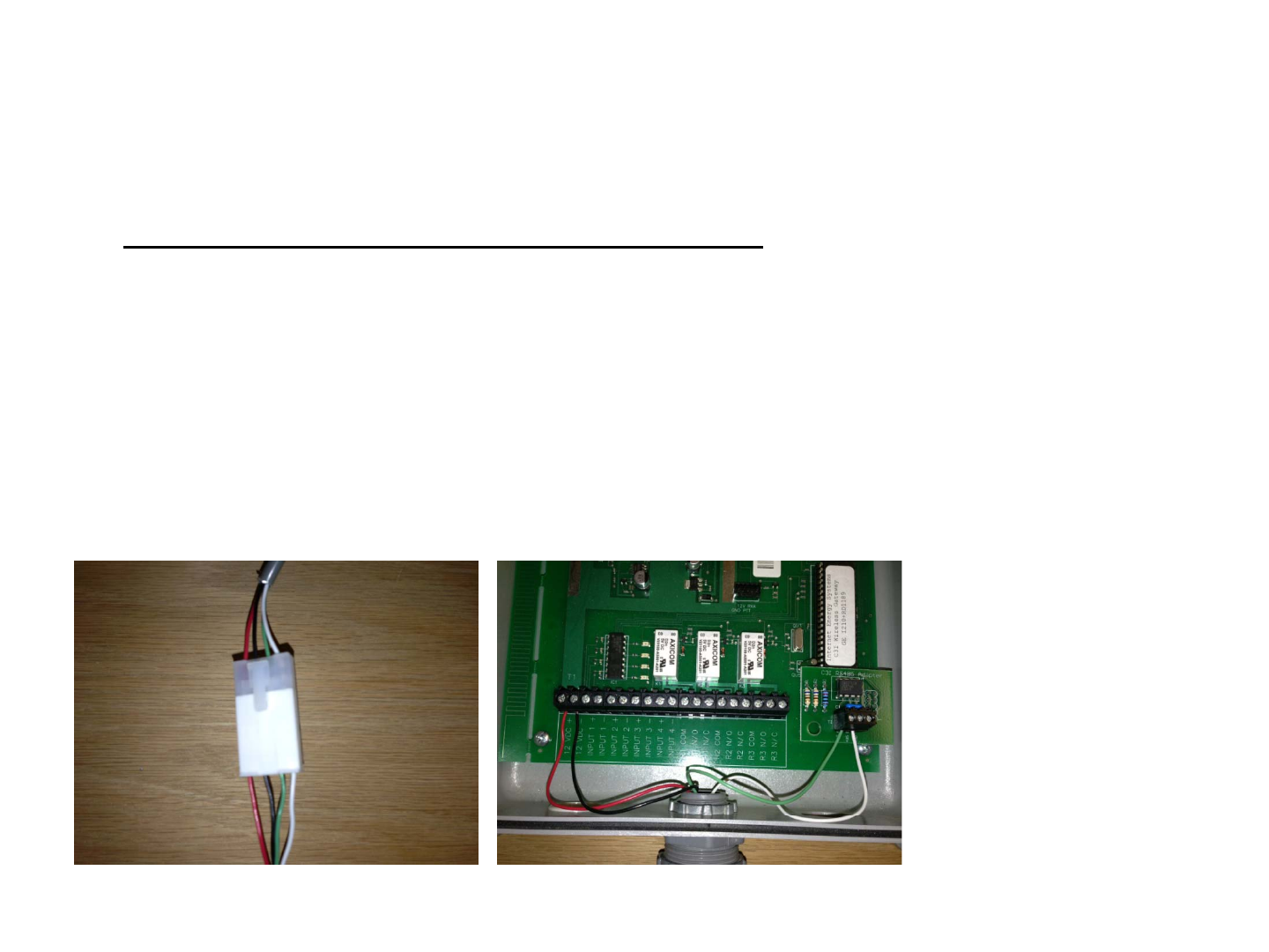
Attach Wiring Harness To Gateway
•GATEWAY GE I210+ Harness
•12 VDC + Red
•12 VDC - Black Wire
•RS 485+ Blue or Green Wire
•RS 485- White Wire
•Install GE Com Module Equipped Electric Meter
•Attach quick connect harness. Gateway should now be operational. Verify operation of
GREEN power/status LED LED will blink continuously on the standard version of the
GREEN
power/status
LED
.
LED
will
blink
continuously
on
the
standard
version
of
the
gateway when assigned meters are not reporting valid data to the C3IWireless Gateway.
•Secure the enclosure with screws, plugs, and a utility seal when installation is finished
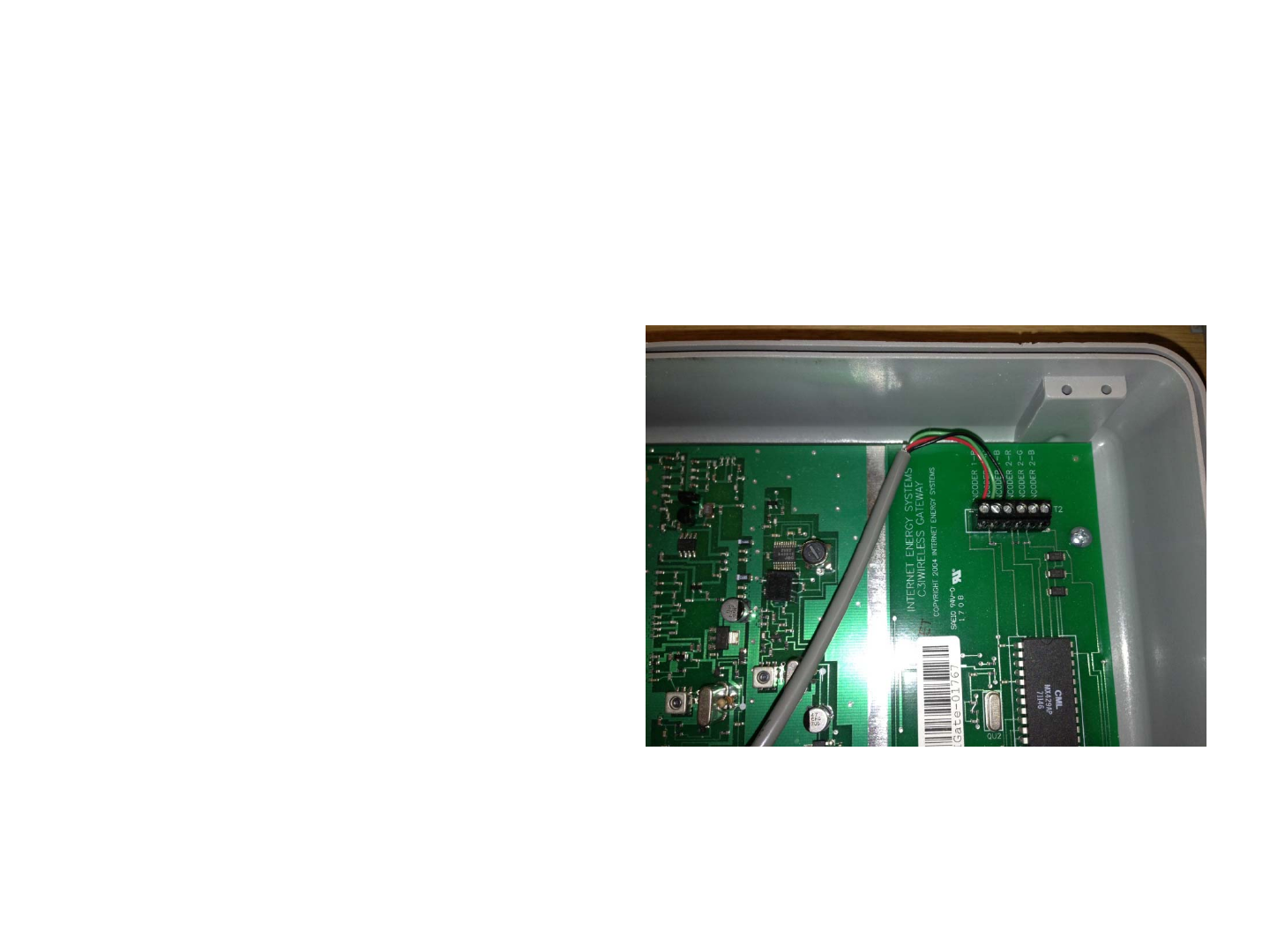
Absolute Encoding Register Meters
• The C3IWireless Standard Gateway can
read Sensus Absolute Di
g
ital Encoder t
yp
e
gyp
water and gas encoders. Encoder meters
utilize a 3 wire connection to the
C3IWireless Gateway. There are two
available input ports for the encoders. The
terminals are labeled R, G, and B and they
are simply wired to the corresponding
are
simply
wired
to
the
corresponding
terminals on the encoder meter head.
• The register reading must be assigned to
one of the 4 input channels on the
C3IWireless Gateway. The C3IConfig PDA
is used to make these assignments.
• Since absolute encoders provide a direct
register reading to the C3IWireless
Gateway, no calibration is required. We
recommend the use of these meters
whenever possible.
•Note: Not all digits are always
transmitted in the encoder protocol.
Depending on register programming the
appropriate multiplier must be used in
the software.

• This device has been evaluated for
compliance with rf exposure limits at a
compliance
with
rf
exposure
limits
at
a
distance of 20 cm. Installation of the device
should be such that a minimum distance of
20 cm can be maintained between the radio
antenna and nearby persons.
• No User Serviceable parts. RF module is
programmed and tuned at factory.
Note: This equipment has been tested and found to comply with the limits for a Class B digital device, pursuant to part 15 of
the FCC Rules. These limits are designed to provide reasonable protection against harmful interference in a residential
installation. This equipment generates, uses and can radiate radio frequency energy and, if not installed and used in
accordance with the instructions, may cause harmful interference to radio communications. However, there is no guarantee
that interference will not occur in a particular installation. If this equipment does cause harmful interference to radio or
television reception, which can be determined by turning the equipment off and on, the user is encouraged to try to correct
the interference by one or more of the following measures:
—Reorient or relocate the receiving antenna.
—Increase the separation between the equipment and receiver.
—Connect the equipment into an outlet on a circuit different from that to which the receiver is connected.
—Consult the dealer or an experienced radio/TV technician for help.
Changes or modifications not expressly approved by the party responsible for compliance could void the user's authority to
operate the equipment.
This device complies with part 15 of the FCC Rules. Operation is subject to the following two conditions: (1) This device may
not cause harmful interference, and (2) this device must accept any interference received, including interference that may
cause undesired operation.