Omron Automotive Electronics Korea OKA-100T RF Keyless Entry System User Manual MANUAL AND BLOCK DIAGRAM
Omron Automotive Electronics Korea Co., Ltd. RF Keyless Entry System MANUAL AND BLOCK DIAGRAM
MANUAL AND BLOCK DIAGRAM

Transmitter, RF Keyless Entry System
OMRON
AUTOMOTIVE
ELECTRONICS
KOREA
OKA-100T
Table of contents
1....Constitution of the Radio Frequency Keyless Entry system Controller for vehicle ------1
2....User's manual (provisionally ------------------------------------------------------------------------ 2
3....Block diagram ------------------------------------------------------------------------------------------3
4....Specification -------------------------------------------------------------------------------------------- 4
5....Features -------------------------------------------------------------------------------------------------- 5

- 1 -
1. Constitution of the Radio Frequency Keyless Entry System for vehicle
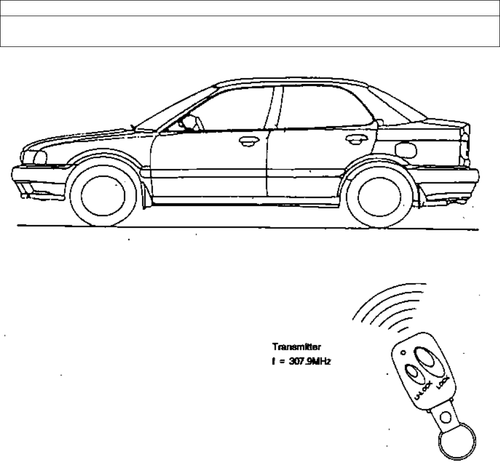
The radio frequency keyless entry is a system that it controlls locking and unlocking the door and the trunk by wireless remote
controller. This system consists of three components. The TRANSMITTER is a device that transmits the signal when the button is
pressed. The transmission signal consists of several synchronous codes, unique identification code, security code and function code.
The RECEIVER is fixed inside the vehicle. It works intermittently to prevent the battery exhaustion. When the receiver detects the
sychronous code, it runs continuously to receive the signals completely. After receiveing the signal, the receiver decides which
operation will be performed. The user can select the following operations by pressing the button of theremote transmitter.
OPERATION ACTION
LOCK lock the door
UNLOCK unlock the door

- 2 -
2. User's manual (provisionally)
REMOTE TRANSMITTER
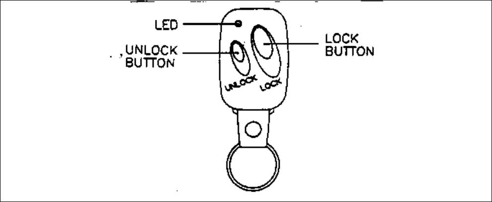
You can lock and unlock your vehicle with the remote transmitter.
LOCK
When you push the LOCK button, all the doors will lock.
You cannot lock any of the doors with the remote transmitter if any door is open or the key is the ignition switch.
UNLOCK
When you push the UNLOCK button, all the doors will unlock.
You cannot unlock any of the doors with the remote transmitter if any door is open or the key is in the ignition switch.

- 3 -
3. Block diagram
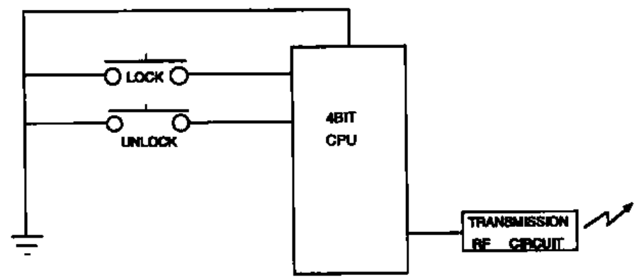
This is block diagram concerning to the transmitter
figure 3.1 block diagram of the transmitter

- 4 -
4. Specification
4.1 CPU
Type
ROM
RAM
EEPROM
Clock frequency
Clock frequency generation
Package
uPD7554AG-540(4bit)
Manufacturer : NEC Corporation
4096 x 8bit(4kbytes)
128 x 4bit
16 x 8bit
500KHz
CR ossillation
20pin DIP
4.2 RF block
Carrer frequency
Frequency generation
Modulation
Bit transmission rate
Dimension
Weigh
Battery
Operation Voltage
Operation Temperature
307.9MHz
SAW resonator
FSK
100bps or 500bps
55.5mm x 37.5mm x 14mm
22.5g
Lithium cell (CR2032)
Manufacturer : PANASONIC Battery corporation etc.
DC3V,10mA
-20+ 60

- 5 -
5.Features
5.1 Transmission frame
The transmission begins immediately in case of LOCK or UNLOCK or button is pressed.
The transmisssion frame consists of the synchronous frame and the data frame. The synchronous frame has 30 synchronous
codes that it will be used for the receiver to wake up. The data frame consists of 24bit length identification code , 16bit security
code and function code. 16million different identification codes are available.
The security code is always changed in case of any of the buttins is pressed. The transmission time is typically 600 milliseconds.
5.2 Battery saving
To prevent the battery exhaustion, the microcomputer of the transmitter is usually inactive. When the button will be pressed,
the microcomputer wakes up immediately and judges which button is pressing. Then the microcomputer constructs the
transmission frame and radiates it from the antenna. After transmitting, the microcomputer switches stand-by mode by itself.
INFORMATION TO THE USER
This equipment has been tested and found to comply with the limits for a Class B digital device, pursuant to
part 15 of the FCC Rules. These limits are designed to provide reasonable protection against harmful
interference in a residential installation. This equipment generates, uses and can radiate radio frequency
energy and, if not installed and used in accordance with the instructions, may cause harmful interference to
radio communications. However, there is no guarantee that interference will not occur in a particular
installation. If this equipment does cause harmful interference to radio or television reception, which can be
determined by turning the equipment off and on, the user is encouraged to try to correct the interference by
one more of the following measures:
Reorient or relocate the receiving antenna.
Increase the separation between the equipment and receiver.
Connect the equipment into an outlet on a circuit different from that to which
the receiver is connected.
Consult the dealer or an experienced radio/TV technician for help.
WARNING
Changes or modifications not expressly approved by the manufacturer could void the user’s authority to operate the
equipment.