Omron Automotive Electronics Korea OKA-950R RF Keyless Entry System (Receiver) User Manual Table of contents
Omron Automotive Electronics Korea Co., Ltd. RF Keyless Entry System (Receiver) Table of contents
User manual

OMRON
AUTOMOTIVE
ELECTRONICS
KOREA
OKA- 950R
Transmitter, RF Keyless Entry System

1. Constitution of the Radio Frequency Keyless Entry
System for vehicle
The radio frequency keyless entry is a s
y
stem that it controls lockin
g
and unlockin
g
the door and the
trunk and the panic by wireless remote controller. This system consists of three components. The TRANSMITTER is
a device that transmits the signal when the button is pressed. The transmission signal consists of several
synchronous codes, unique identification code, security code and function code and crc code. The RECEIVER is
fixed inside the vehicle. It works intermittently to prevent the battery exhaustion. When the receiver detects the
synchronous code, it runs continuously to receive the signals completely. After receiving the signal, the receiver
decides which operation will be performed.
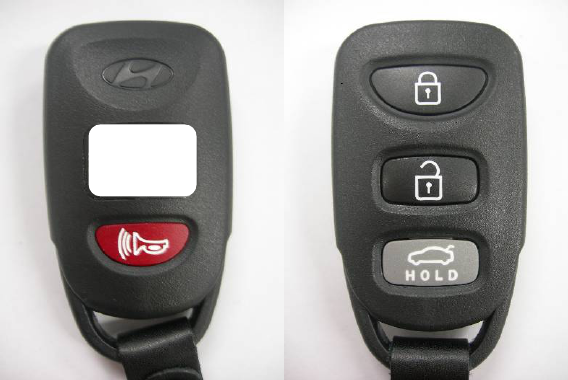
The user can select the following operations by pressing the button of the remote transmitter.
OPERATION ACTION
LOCK lock the door
UNLOCK unlock the door
TRUNK open the trunk
PANIC alarm the horn
Transmitter
f = 313.85MHz
- 1 -

2. User's manual (provisionally)
REMOTE TRANSMITTER
OKA-
950T
You can lock and unlock your vehicle with the remote transmitter.
LOCK
When you push the LOCK button, all the doors will lock.
You cannot lock any of the doors with the remote transmitter if any door is open or the key is the ignition switch.
UNLOCK
When you push the UNLOCK button, all the doors will unlock.
You cannot unlock any of the doors with the remote transmitter if any door is open or the key is in the ignition
switch.
TRUNK
When you push continuously the TRUNK button during 1s, TRUNK will open.
PANIC
When you push the PANIC button, horn will alarm.
- 2 -

4. Specification
4.1 CPU
Type
ROM
RAM
Clock frequency
Clock frequency generation
Package
MC9S12XS256J0MAL(16bit)
Manufacturer : Freescale
256KByte
12KByte
4MHz
Crystal resonator
112pin LQFP
4.2 RF Receive Module
Type
Local clock frequency
Frequency generation
G8X-21RX-KO1
Manufacturer: OMRON KOREA
313.85MHz
Crystal resonator
Modulation Scheme FM(superheterodyne)
Bandwidth ±200 KHz
Carrier Detect Sensitivity 11dBuVemf
4.3 Others
Dimension 149mm× 119mm × 35mm
Weigh 326g
Battery CAR Battery(DC 12V)
Operation Voltage, Current DC12V,50mA (4mA on standby)
-40℃ ∼ +80℃
- 4 -
5.Features
5.1 Door lock control
The LOCK relay in the receiver drives the door lock actulators to "LOCK"-side when LOCK button of
transmitter was pressed. The UNLOCK relay in the receiver drives
5.2 Battery saving
To prevent the battery exhaustion , the micro-computer of the transmitter is usually inactive. When the button
will be pressed, the micro-computer wakes up immediately and judges which button is pressing. Then the
micro-computer constructs the transmission frame and radiates it from the antenna .After transmitting, the
micro-computer switches stand-by mode by itself.
6. Derivatives
OKA-950R is an integrated controller for a car body control, includes the keyless entry receiver.
The integrated. controller consists of the multiple control functions as follows, centralized door lock,
turn-signal lamp, room-lamp, intermitted wiper, power window timer, ignition key illumination,
warning buzzer and so on.
- 5 -
Note : This equipment has been tested and found to comply with the limits for a Class B digital device, pursuant to part
15 of the FCC Rules. These limits are designed to provide reasonable protection against harmful interference in a
residential installation This equipment generates, uses and can radiate radio frequency energy and, if not installed and
used in accordance with the instructions, may cause harmful interference to radio communications, However, there is
no guarantee that interference will not occur in a particular installation. If this equipment does cause harmful
interference to radio or television reception, which can be determined by turning the equipment off and on, the user is
encouraged to try to correct the interference by one or more of the following measures:
- Reorient or relocate the receiving antenna.
- Increase the separation between the equipment and receiver.
- Connect the equipment into an outlet on a circuit different from that to which the receiver is connected.
- Consult the dealer or an experienced radio/TV technician for help.
Modifications not expressly approved by the manufacturer could void the user's authority to operated the equipment
under FCC rules.