Omron RFID Business Development Department V740-BA50C2A RFID Reader Transmitter User Manual
Omron Corporation, RFID Business Development Department RFID Reader Transmitter
User Manual

V740 RFID READER/WRITER, ANTENNA 2005-09, REV.01
OPERATION MANUAL 1 of 56 ©OMRON CORPORATION 2005
V740-series
UHF RFID System
Operation Manual
V740-BA50C22A-US (Bi-static Reader/Writer)
V740-HS02CA (Circular Antenna)
V740-HS02C (Circular Antenna)
Cat.No. RFM – XXX – XX
Reader/Writer
Antenna

V740 RFID READER/WRITER, ANTENNA 2005-09, REV.01
OPERATION MANUAL 2 of 56 ©OMRON CORPORATION 2005
PRECAUTIONS
Please read and understand this manual before using the products. Please consult your OMRON representative if you
have any question or comments.
WARRANTY: OMRON’S EXCLUSIVE WARRANTY IS THAT THE PRODUCTS ARE FREE FROM DEFECTS IN MATERIALS AND
WORKMANSHIP FOR A PERIOD OF ONE YEAR (OR OTHER PERIOD IF SPECIFIED) FROM DATE OF SALE BY OMRON.
OMRON MAKES NO WARRANTY OR REPRESENTATION, EXPRESS OR IMPLIED, REGARDING NON-INFRINGEMENT,
MERCHANTABILITY, OR FITNESS FOR PARTICULAR PURPOSE OF THE PRODUCTS. ANY BUYER OR USER ACKNOWLEDGES THAT
THE BUYER OR USER ALONE HAS DETERMINED THAT THE PRODUCTS WILL SUITABLY MEET THE PREQUIREMENTS OF THEIR
INTENDED USE. OMRON DISCLAIMS ALL OTHER WARRANTIES, EXPRESS OR IMPLIED.
LIMITATIONS OF LIABILITY: OMRON SHALL NOT BE RESPONSIBLE FOR SPECIAL, INDIRECT, OR CONSEQUENTIAL
DAMAGES, LOSS OF PROFITS OR COMMERCIAL LOSS IN ANY WAY CONNECTED WITH THE PRODUCTS, WHETHER SUCH CLAIM
IS BASED ON CONTRACT, WARRANTY, NEGLIGENCE, OR STRICT LIABILITY.
IN NO EVENT SHALL THE RESPONSIBILITY OF OMRON FOR ANY ACT EXCEED THE INDIVIDUAL PRICE OF THE PRODUCT ON
WHICH LIABILITY IS ASSERTED.
IN NO EVENT SHALL OMRON BE RESPONSIBLE FOR WARRANTY, REPAIR, OR OTHER CLAIMS REGARDING THE PRODUCTS
UNLESS OMRON'S ANALYSIS CONFIRMS THAT THE PRODUCTS WERE PROPERLY HANDLED, STORED, INSTALLED, AND
MAINTAINED AND NOT SUBJECT TO CONTAMINATION, ABUSE, MISUSE, OR INAPPROPRIATE MODIFICATION OR REPAIR.
SUITABLITY FOR USE : OMRON SHALL NOT BE RESPONSIBLE FOR CONFORMITY WITH ANY STANDARDS, CODES, OR
REGULATIONS THAT APPLY TO THE COMBINATION OF THE PRODUCTS IN THE CUSTOMER'S APPLICATION OR USE OF THE
PRODUCT.
TAKE ALL NECESSARY STEPS TO DETERMINE THE SUITABILITY OF THE PRODUCT FOR THE SYSTEMS, MACHINES, AND
EQUIPMENT WITH WHICH IT WILL BE USED.
KNOW AND OBSERVE ALL PROHIBITIONS OF USE APPLICABLE TO THIS PRODUCT.
NEVER USE THE PRODUCTS FOR AN APPLICATION INVOLVING SERIOUS RISK TO LIFE OR PROPERTY WITHOUT ENSURING
THAT THE SYSTEM AS A WHOLE HAS BEEN DESIGNED TO ADDRESS THE RISKS, AND THAT THE OMRON PRODUCT IS
PROPERLY RATED AND INSTALLED FOR THE INTENDED USE WITHIN THE OVERALL EQUIPMENT OR SYSTEM.
CHANGE IN SPECIFICATIONS : PRODUCT SPECIFICATIONS AND ACCESSORIES MAY BE CHANGED AT ANY TIME BASED
ON IMPROVEMENTS AND OTHER REASONS. CONSULT WITH YOUR OMORN REPRESENTATIVE AT ANY TIME TO CONFIRM
ACTUAL SPECIFICATIONS OF PURCHASED PRODUCT.
Regulatory Compliance
EMC ...................................................................47 CFR, Part 15
................................................................................RSS210
Safety........................................................................... UL 60950
....................................................Can/CSA C22.2 No 60950
FCC COMPLIANCE: This equipment complies with Part 15 of the FCC rules for intentional radiators and Class A digital
devices when installed and used in accordance with the operation manual. Following these rules provides reasonable
protection against harmful interference from equipment operated in a commercial area. This equipment should not be
installed in a residential area as it can radiate radio frequency energy that could interfere with radio communications, a
situation the user would have to fix at their own expense.
EQUIPMENT MODIFICATION CAUTION: Equipment changes or modifications not expressly approved by OMRON
Corporation, the party responsible for FCC compliance, could void the user's authority to operate the equipment and
could create a hazardous condition.
IMPORTANT USER INFORMATION: In order to comply with FCC/IC requirements for RF exposure safety, a separation
distance of at least 23 cm (9.1in) needs to be maintained between the radiating elements of the antenna and the bodies
of nearby persons. This transmitter must not be co-located or operated in conjunction with any other antenna or
transmitter.
©Copyright OMRON Corporation 2005. All rights reserved.
This document is protected by copyright and is intended solely for use in conjunction with the product. Notify your
OMRON representative before copying or reproducing this document in any manner, for any other purpose.
Warranty, Limitations of Liability
Application Precautions, Change in Specifications
Declarations
V740 RFID READER/WRITER, ANTENNA 2005-09, REV.01
OPERATION MANUAL 3 of 56 ©OMRON CORPORATION 2005
Safety Precautions
This chapter provides important information for the safe use of this product.
Ensure to read the information carefully before use.
IN THE SAFETY PRECAUTIONS BELOW, SEVERITY IS CATEGORIZED AS EITHER ”WARNING”
OR “CAUTION”.
Warning
Indicates a potentially hazardous situation which, if not avoided, could result
in minor or moderate injury, or may result in serious injury or death.
Additionally there may be significant property damage.
Caution Indicates a potentially hazardous situation which, if not avoided, may result
in minor or moderate injury, or property damage.
Property damage refers to extended damage caused to house/household
goods or livestock/pets.
●Description of Symbols
Prohibition
Indicates an action or activity not permitted.
Observe strictly
Indicates the need to ensure the safe use of the product.
Ensure to establish a solid grounding
A label indicating that a device with a grounding terminal should always be
grounded.
Electric shock hazard
A notification that alerts the possibility of electric shock under certain
conditions.
Do not disassemble
A notification that prohibits disassembly when injuries caused by electric
shocks may result.
Please ensure that all cautions and prohibitions are adhered to, since non-compliance may lead to serious injury
or damage, in certain circumstances.
V740 RFID READER/WRITER, ANTENNA 2005-09, REV.01
OPERATION MANUAL 4 of 56 ©OMRON CORPORATION 2005
警 WARNING
Never disassemble, repair, or modify the main unit and cables.
z Do not disassemble, repair, or modify this product. Doing so may result in electric shock, fire, or personal
injury.
Do not handle the device with wet hands. Do not touch the terminals while the device is
connected to the power supply.
z Electric shock hazard.
Do not allow the cables to be in contact with heaters.
z The cable sheaths may melt and the exposed wire may cause electric shock or fire.
Be sure a solid grounding is established for the device.
z Electric shock hazard.
Do not use the power cords and power adapters not supplied with the products.
z Failure to do so may results in electric shock, fire, or personal injury.
Connect and disconnect cables as described in the following procedures when installing,
moving, on this product or attached devices.
To connect: To disconnect:
1. Turn everything OFF. 1. Turn everything OFF.
2. Attached all cables to devices. 2. Remove power cords from outlet.
3. Attached power cords to outlet. 3. Remove all cables from devices.
Failure to do so may result In spark or deform or damage the device.
Caution
Do not drop the device you may receive major shocks.
z Doing so may result in personal injury or device damage.
Do not apply strong force to, or place heavy items on the device or cables.
z Doing so may deform or damage the device, resulting in electric shock or fire.
Use and store the product in an environment that is specified in the catalog or operation
manual.
z Failure to do so may cause failure of the device, electric shock, or fire. Do not use or store the device in the
following locations:
・ Locations that do not satisfy the specified operating conditions (0 to +40℃, 35%RH to 85%RH,non-
condensing).
・ Locations that do not satisfy the specified storage conditions (-25 to +65℃, 35%RH to 85%RH,non-
condensing).
・ Locations where the Reader/Writer is exposed to direct sunlight.
V740 RFID READER/WRITER, ANTENNA 2005-09, REV.01
OPERATION MANUAL 5 of 56 ©OMRON CORPORATION 2005
・ Locations where the Reader/Writer is exposed to dust, corrosive gas, saline, or flammable gas.
・ Locations where the Reader/Writer is exposed to direct heat.
・ Locations subject to condensation due to high humidity.
・ Locations subject to vibration or impact that exceed the limits outlined in the specifications.
・ Locations where the device may be exposed to water, oil, or chemical agents. (This applies to
the models other than waterproof types.)
・ Outdoor
Be sure to tighten the devices screws securely.
z Failure to do so may result in personal injury or device damage.
Cables with screw attachments must be secured before use.
z Failure to do so may damage the device.
To avoid interferences with other systems, adhere to the following items and check them
before using the product.
z The product uses a publicly available ISM frequency band of 902-928MHz to communicate with Tags. Some
transceivers, motors, monitoring devices, power supplies (power supply ICs), and other similar RFID systems
may generate noise, which cause radio interference and may affect communication with Tags. If the product is
required in the vicinity of these items, check for any interferences prior to use.
z On the contrary, the system itself may affect radio station transmissions or medical devices. Be cautious
when using the system in the environments where such effects might occur.
z To minimize noise effects, adhere to the following:
・Establish a Class D grounding (former Class 3 grounding) for metal objects placed in the vicinity of the
system.
・Keep cables away from those with high voltages or heavy currents.
Do not allow the device or cables to be exposed to water.
z Doing so may result in electric shock, fire or failure of non-waterproof devices or cables.
If the device fails or is exposed to water (non-waterproof devices or parts), or an unusual
smell, smoke, or sparks are detected, immediately refrain from using the device and
contact OMRON or a sales representative for service and repair.
z Continued use of the failed device may result in electric shock or fire.
Do not use damaged cables.
z Continued use of the damaged cables may result in electric shock or fire.

V740 RFID READER/WRITER, ANTENNA 2005-09, REV.01
OPERATION MANUAL 6 of 56 ©OMRON CORPORATION 2005
Table of Contents
1. Installation and Usage Guide ................................................................................7
1.1 Before You Begin.........................................................................................................................8
1.1.1 Installation Requirements...................................................................................................8
1.1.2 Performance Considerations..............................................................................................8
1.2 Authorized Antennas ...................................................................................................................9
1.2.1 Antennas ............................................................................................................................9
1.2.2 Antenna Cables(Options)...................................................................................................9
1.2.3 Setting the Reader RF Power ............................................................................................9
1.3 Reader Installation.....................................................................................................................10
1.3.1 Install the Reader .............................................................................................................10
1.3.2 Install the Antennas..........................................................................................................10
1.3.3 Connect the Reader.........................................................................................................10
1.3.4 I/O Interface......................................................................................................................12
1.4 Reader Configuration.................................................................................................................13
1.5 Reader Service ..........................................................................................................................14
1.5.1 Using the Browser-Based Interface .................................................................................14
1.5.2 Restarting the Reader......................................................................................................25
1.5.3 Using Safe Mode..............................................................................................................26
1.6 Tag Fundamentals....................................................................................................................27
1.7 Specifications.............................................................................................................................28
2. Query Protocol .....................................................................................................29
2.1 Transport Protocol .....................................................................................................................29
2.1.1 TCP Connection Setup and Teardown ............................................................................29
2.2 Event/Query Protocol.................................................................................................................30
2.2.1 Client Software Requests/Functionality ...........................................................................30
2.2.2 General Observations, Commands, and Syntax..............................................................31
2.2.3 Extended RQL Command Structure supported by the V740 Reader..............................31
2.2.4 Detailed Command Structure...........................................................................................32
2.2.4.1 ID Read......................................................................................................................32
2.2.4.2 ID Write – Writing data to tag ....................................................................................36
2.2.4.3 Get Information..........................................................................................................44
2.2.5 Errors................................................................................................................................45
2.2.6 Protocol Specific Functionality and Parameter Settings..................................................47
2.2.6.1 915 MHz EPC Class 1/1B .........................................................................................47
2.3 Examples ...................................................................................................................................48
2.3.1 Example 1 ........................................................................................................................48
2.3.2 Example 2 ........................................................................................................................48
2.3.3 Example 3 ........................................................................................................................48
3. I/O..........................................................................................................................49
3.1 Using the input/output function ..................................................................................................49
3.2 Detailed Command structure.....................................................................................................49
4. Characteristics(Reference) .................................................................................50
4.1 Communications Range ............................................................................................................50
4.2 Communications Time...............................................................................................................51
APPENDIX : OUTLINE DRAWINGS.........................................................................52
Reader : ( V740-BA50C22A-US) ..............................................................................................52
Antenna : ( V740-HS02CA,V740-HS02C)..............................................................................53
Antenna Cable:..........................................................................................................................54

V740 RFID READER/WRITER, ANTENNA 2005-09, REV.01
OPERATION MANUAL 7 of 56 ©OMRON CORPORATION 2005
V740 Series RFID system
Reader/Writer
Antenna
Operation Manual
V740-BA50C22A-US Bi-static Reader/Writer(8ports)
V740-HS02CA Bi-static Antenna(Circular)
V740-HS02C Bi-static Antenna(Circular)
The OMRON V740 RFID Reader (herein after
denoted as the V740 Reader) uses RFID (radio
frequency identification) technology to read data
stored on RFID tags. The V740 reader operates
analogous to an SQL (structured query language)
server, providing tag data in response to requests
from another application. A separate software
application may be used to direct its operation and
provide a user interface.
The reader supports UHF (ultra high frequency)
antennas, which are available separately. The
reader supports multiple configurations of UHF
antenna ports and transfers data to a remote
computer over a network connection.
The V740 Reader is powered by ThingMagic LLC
Mercury4® technologies.
1. Installation and
Usage Guide
About this Guide
This installation and usage guide explains how to
install the V740 Reader, how to use the browser-
based interface, and how to control the reader
remotely.

V740 RFID READER/WRITER, ANTENNA 2005-09, REV.01
OPERATION MANUAL 8 of 56 ©OMRON CORPORATION 2005
1.1 Before You Begin
1.1.1 Installation Requirements
• The reader is shipped with a power source with
a cable length of 1.8m (6ft).
• Use only authorized antennas and cables to
maintain FCC approval .
• Properly shielded a grounded cables and
connectors must be used for connection to
host computer and / or peripherals in order to
meet FCC emission limits.
(AC adaptor) with ferrite core must be used
for RF interference suppression.
• Provide strain relief for all reader connections.
• The minimum screw size for mounting the
reader is #12 (M5). Use suitable wall anchors
when mounting to drywall or masonry.
• A Shielded Ethernet cable must be used to
communicate with other devices.
• Multiple readers and antennas can be used in
combination to enhance detection at specific
locations provided the software application is
able to synchronize antenna operation.
• Recommended minimum configuration for a
computer running an application that interfaces
with the V740 Reader:
– Pentium® 400 MHz processor
– 128MB memory
– 10 GB hard disk drive
– Base-T-10/100 Ethernet® port
1.1.2 Performance Considerations
Reader performance may be affected by external
factors including tag variables and environment.
Performance tests conducted under typical
operating conditions at your site are recommended
to help you optimize system performance.
Tag Variables
There are several variables associated with tags
that can affect reader performance:
• Application surface — Some materials interfere
with tag performance including metal and
moisture. Tags applied to items made from or
containing these materials may not perform as
expected.
• Tag orientation — Reader performance is
affected by the orientation of the tag in the
antenna field.
• Tag model — many tag models are available.
Each model has its own performance
characteristics(refer to Chapter 3).
Environment
Reader performance may be affected by the
following:
• Metal surfaces such as desks, filing cabinets,
bookshelves, and wastebaskets may enhance
or degrade reader performance.
Mount antennas as far as possible from metal
surfaces that are adversely affecting system
performance.
• Devices that operate at 900 MHz, such as
cordless phones and wireless LANs, can
interfere with reader performance.
These devices may degrade performance of
the reader. The reader may also adversely
affect performance of 900 MHz devices.
• Antennas operating in close proximity may
interfere with one another, thus degrading
reader performance.
• Interference from other antennas may be
eliminated or reduced by using either one or
both of the following strategies:
– Affected antennas may be synchronized by a
separate user application using a time-
multiplexing strategy.
– Antenna power can be reduced by reconfiguring
the RF Transmit Power setting for the reader.

V740 RFID READER/WRITER, ANTENNA 2005-09, REV0.1
OPERATION MANUAL 9 of 56 ©OMRON CORPORATION 2005
1.2 Authorized Antennas
The antenna authorized by the FCC for use with the
V740 Reader is described below.
IMPORTANT: No other antennas may be used with
the V740 Reader without violating FCC regulations. It
is the responsibility of the user to comply with this
requirement.
1.2.1 Antennas
Bi-static Circular Antenna(Options)
Model: V740-HS02CA, V740-HS02C
Polarization: Circular
Gain: 6dBi max.
Connector: N-Female
Cable length : 0.3m(0.98’)
1.2.2 Antenna Cables(Options)
The only cables authorized by the FCC for use with
the V740 Reader are listed below:
Short cable
Model: V740-A01-3.0M
Length: 3.0m(9.8')
Insertion Loss: 1.5 dB min.
Cable Type: 3D-2V
Connector: Reverse TNC to Type N
Cable Diameter : 5.5mm(0.22’’)
Long cable
Model: V740-A01-10M
Length: 10m(32.8')
Insertion Loss: 1.5 dB min.
Cable Type:5D-SFA
Connector: Reverse TNC to Type N
Cable Diameter : 7.6mm(0.30’’)
1.2.3 Setting the Reader RF Power
During initial installation, the reader must be properly
configured to use the correct RF power to comply with
FCC regulations. DO NOT increase the power beyond
the recommended power setting as calculated below.
The maximum RF power is determined from antenna
gain and antenna cable loss using the formula:
Pmax = 36 dBm - Antenna Gain + Cable Loss
For example, if the antenna has a maximum gain of 6
dBi, and the cable has a minimum loss of 1.5 dB, the
maximum RF power that may be set is (36- 6 + 1.5) =
31.5 dBm.
The Reader RF Power is set through the Settings
Page as described on Page18.
Note that in no case may the power be set higher than
31.5 dBm.
Recommended Power Settings
Antenna Type Short Cable/Long Cable
V740-HS02CA
V740-HS02C
31.5 dBm
V740 RFID READER/WRITER, ANTENNA 2005-09, REV0.1
OPERATION MANUAL 10 of 56 ©OMRON CORPORATION 2005
1.3 Reader Installation
The following parts are provided with the reader:
Part Qty. Part Number
V740-Reader/Writer 1 V740-BA50C22A-US
Power Supply 1 -
1.3.1 Install the Reader
You can place the reader on a shelf or mount it to a
wall. Mounting shelf and wall should be flat to fix the
reader securely.
To mount the reader on a wall:
1. Hold the reader in its four mounting location and
mark the position of the mounting screws
2. Drill holes for the screws and install wall anchors if
required. Be sure anchors must have enough
strength to fixed the reader against vibration.
3. Insert the M5x16 screws with spring washers and
flat washers and tighten until almost flush with the
wall.
4. Slip the reader over the screws and slide down to
lock the screws in the keyhole openings.
5. Tighten the screws securely.
6. Fix the AC adaptor so that not to move by
vibration and tense DC plug cables. Do not bundle
the adaptor cable with other signal or power lines.
Mechanical Loading - Mounting of the equipment in
the rack should be such that a hazardous condition is
not achieved due to uneven mechanical loading.
1.3.2 Install the Antennas
The antennas can be mounted directly to a variety of
surfaces. Mounting surfaces should be flat to fix the
antenna securely.
To mount the reader on a wall :
1. Hold the antenna in its mounting location and
mark the position of the mounting screws with
minimum (4) points. The antenna has several
mounting holes for each side. Choose 4 of those
with diagonal position according to the mounting
location.
Drill holes for the screws and install wall anchors if
required.
2. Insert the M4x20 screws with spring washers and
flat washers and tighten until almost flush with the
wall.
3. Tighten the screws securely.
Note: For best performance, mount the antenna in
the horizontal orientation as pictured above.
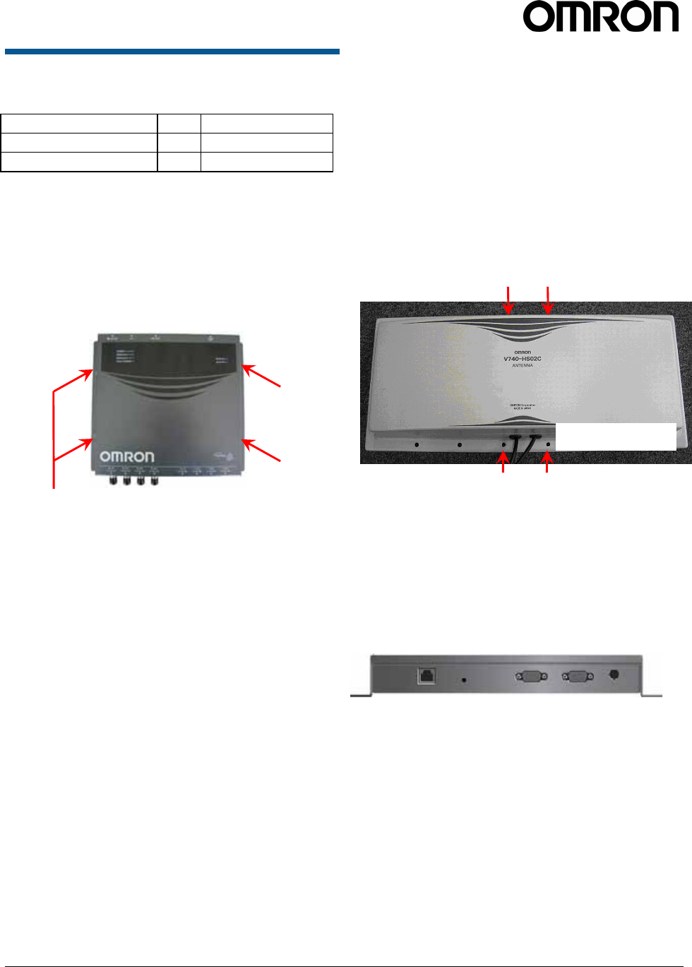
1.3.3 Connect the Reader
A B C D E
A = RJ-45 Ethernet port 10/100Base-T
B = Safe Mode button
C = RS232C (Do not use)
D = I/O port (Non LPS)
E = DC power input
Note: MAC Address is displayed on the lower part of
RJ-45 Ethernet port.
Mountin
g
holes
Mountin
g
holes
V740 RFID READER/WRITER, ANTENNA 2005-09, REV0.1
OPERATION MANUAL 11 of 56 ©OMRON CORPORATION 2005
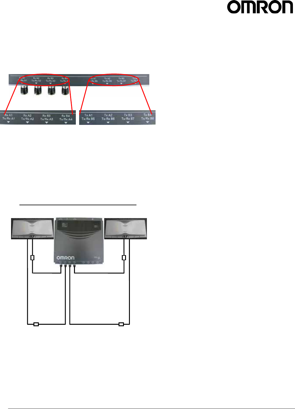
One to four OMRON Bi-static antennas(V740-
HS02CA,02C) can be connected to the reader,
depending on the application requirements. The lower
row of silk-screen markings on the reader identifies
the port number and antenna connections.
Note: Upper row of silk-screen marking on the reader
is reserved for future use.
1. Connect required UHF antennas to the antenna
ports on the reader .
IMPORTANT: Connect antennas to the antenna
ports before applying power to the reader. Any
antenna port not having an antenna connected to
it will be disabled when the reader is powered on.
Antenna Connection : V740-BA50C22A-US
Note: With the two antenna configuration, there is
a possibility that a tag may be read by an inactive
antenna if the tag is located with in approximately
20 cm of the inactive antenna.
2. Verify that all antennas are securely connected.
3. Connect the reader to the network by plugging a
Shielded Ethernet cable into the Ethernet port.
or
Connect the reader to a PC (personal computer)
by plugging a crossover Shielded Ethernet cable
into the Ethernet port.
Note: If DHCP is to be used, then the network
and server must be connected before powering
up the reader. If a DHCP server is not found the
reader will fall back to the IP address:
“10.0.0.101”.
Note: If NTP is to be used, then the network must
be connected and the server must be available
before powering up the reader. If a NTP server is
not found. The reader will not set the current time.
4. Plug the power adapter provided with the reader
into the DC power input connector. Then connect
the AC power cord to a power outlet.
While the reader is powering up, one green light
will be on. After the reader finishes its power-on
self-test, approximately 45 seconds, the green
light will pulse. The reader is now ready for
operation.
Antenna Cable x4
(
V740-A01
)
Antenna x2
(
V740-HS02CA
)
V740 RFID READER/WRITER, ANTENNA 2005-09, REV0.1
OPERATION MANUAL 12 of 56 ©OMRON CORPORATION 2005
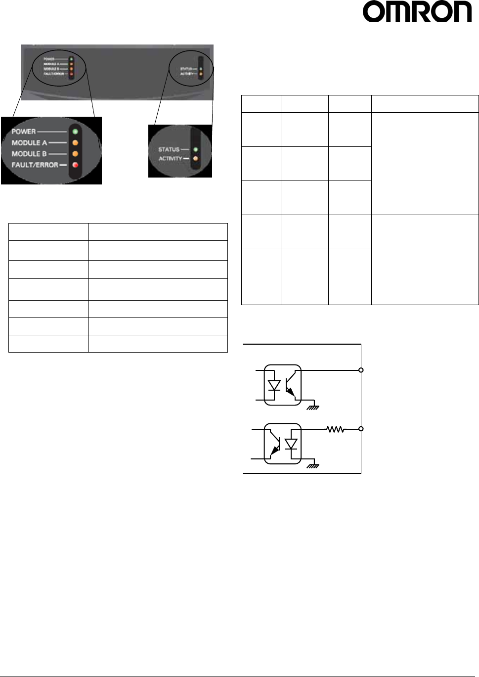
LED Indicators
Name Meaning
POWER Lights while booting.
Blinks when the reader is running.
MODULE A Lights when communicating with tags
via MODULE A(Antenna port 1 and 2)
MODULE B Lights when communicating with tags
via MODULE B(Antenna port 3 and 4)
FAULT/ERROR Lights when system error occurs.
STATUS Reserved for Future Use
ACTIVITY Reserved for Future Use
IMPORTANT: DO NOT disconnect power during
startup. Disconnecting power while booting the V740
reader may result in improper startup.
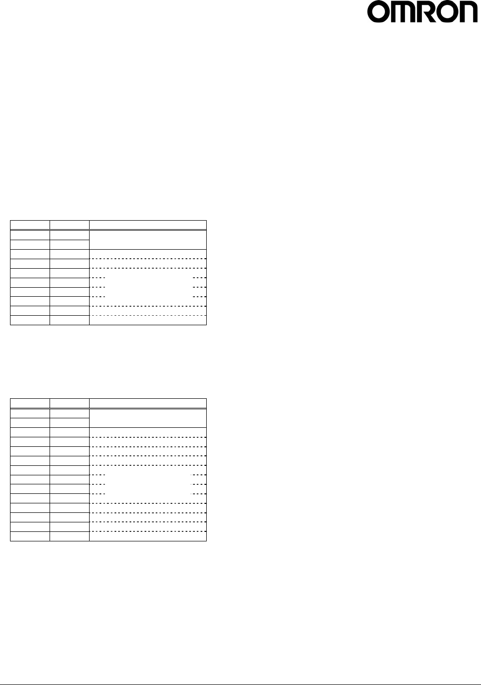
1.3.4 I/O Interface
The Reader provides control of and response to the
I/O(Input/Output) lines.
I/O connector is D-sub(9pin) Male connector.
Name Pin No. IN/OUT Interface
I/O_0 6 OUT
I/O_1 1 OUT
I/O_2 9 OUT
Open-collector output
24VDC maximum,
20mA maximum
I/O_3 4 IN
I/O_4 7 IN
Photo-coupler input
Control capacity
20mA maximum
5~10mA typical
Internal resistance
360ohm
360Ω
V740 Reader
Open-collector output
24VDC max.
20mA max.
Photo-coupler input
Control capacity
20mA max.
5~10mA typ.
Internal resistance 360ohm

V740 RFID READER/WRITER, ANTENNA 2005-09, REV0.1
OPERATION MANUAL 13 of 56 ©OMRON CORPORATION 2005
1.4 Reader Configuration
In some cases, the application software may provide
support for reader configuration. If so, follow the
instructions provided with the application.
The following procedure describes how to configure
the reader directly from a network PC using the
browser-based interface.
The reader is shipped to use DHCP by default but will
fall back to the following static network configuration if
it does not get a DHCP lease:
IP Address: 10.0.0.101
Subnet Mask: 255.255.255.0
Gateway: 10.0.0.1
If you are not using DHCP, you must know the IP
address and subnet mask settings for the network
environment in which the reader will be running. If you
are using DHCP, you must have a means of finding
the reader, typically by having a DHCP server update
a DNS server. Another way of finding readers on a
network is to use the Zeroconf protocol, which Apple
calls Bonjour™. (formerly called Rendezvous. Apple
provides a downloadable Bonjour plug-in for Windows
Internet Explorer at their web site:
http://www.apple.com/macosx/features/bonjour/).
Note: Please contact Apple about operating the
Bonjour ™ technology.
1. Exit any reader applications that are running on
the network.
IMPORTANT: Running another reader application
while using the browser-based interface may
cause a reader error. If this happens, reboot the
reader or restart the system using the browser-
based interface.
2. Verify that the reader is operational. All LED’s
should be out except for the green power LED
which should be pulsing.
3. Start a Java-enabled web browser from any
network-enabled PC. This PC must be configured
with an IP address and subnet mask compatible
with the reader’s settings. For example:
IP address 10.0.0.10
Subnet mask 255.255.255.0
4. Browse to…
http://v740 (dhcp name) or
http://10.0.0.101
The V740 reader browser-based interface to the
reader is displayed.
5. Click the Settings link in the navigation menu.
The Modify Settings page appears.
6. If you wish to use DHCP, modify the “Use
DHCP?” setting by selecting the “Yes” radio
button; otherwise, enter the required network
settings in the IP Address, Subnet Mask, and
Gateway fields. The fields will turn red if the
gateway is not on the same subnet as the IP
address. Then, click the [Save Changes] button.
IMPORTANT: Do not disconnect power until the
save process is completed.
7. Set the reader RF power per instructions on page
to correspond to antenna and cable types.
8. Verify that the settings shown are correct. Then,
restart the reader by disconnecting the power
cable and then reconnecting it.
It may take about 60 seconds for the reader to
restart. If the reader IP address was changed, you
must type the new address into the PC browser
address field to communicate with the reader.
IMPORTANT: Do not disconnect and connect
power cable at the DC cord. Always disconnect
and connect power cable at the AC cord.
9. Once the system restarts, click Settings. You are
taken to the Modify Settings page. Your changes
will be saved and then applied. After the reader
reconfigures its network interfaces, it will
automatically redirect you to its status page.
There is no need to restart the reader.
IMPORTANT: Do not disconnect power while the
reader is saving its new configuration.
The reader is now ready to receive commands
from the network.
10. Use the Query page of the browser-based
interface to verify the reader and antenna
operation by reading tags.
11. Close the browser window. Start an application to
control the reader on the network.
V740 RFID READER/WRITER, ANTENNA 2005-09, REV0.1
OPERATION MANUAL 14 of 56 ©OMRON CORPORATION 2005
1.5 Reader Service
1.5.1 Using the Browser-Based
Interface
The browser-based interface communicates directly
with the V740 reader. It includes several tools that
enable you to monitor reader performance, change
reader settings, and upgrade reader firmware.
A navigation menu provides access to the following
pages:
• Status—Displays current operational settings.
• Query—Allows the user to set timing of operation,
set antennas, set RF air interface protocols, and
read tags.
• Write—Allows the user to write tags; this is only
applicable to tags that are writeable.
• Settings—Allows the user to modify radio and
network settings.
• Firmware—Allows the user to upgrade the V740
reader with new firmware images supplied by
OMRON.
• Restart—Allows the user to restart the reader.
• Diagnostics—Provides the current operating
settings of the reader.
• Help—Provides information that is helpful in
operating the reader.
The browser-based interface can be run from any PC
on the network. Care must be taken to configure the
PC with an IP address and subnet mask compatible
with the current operational settings of the reader.
To start the browser-based interface:
1. Exit all reader applications on the network.
IMPORTANT: Running another reader application
while using the browser-based interface may
cause a reader error. If this happens, reboot the
reader or restart it using the browser-based
interface.
2. Start a Java-enabled web browser from any
network-enabled PC.
3. Type the IP address of the reader to which you
want to communicate in the address field of the
browser or use Apple’s Bonjour™ protocol to
browse to it.
4. A log-dialog appears. Enter the factory-installed
name: "web" and the password: "radio"(all lower
case)
5. A navigation menu and the V740 reader
“Mercury4” Status page appear in the browser.
Descriptions for each page are the following:
Navigation menu
V740 RFID READER/WRITER, ANTENNA 2005-09, REV0.1
OPERATION MANUAL 15 of 56 ©OMRON CORPORATION 2005
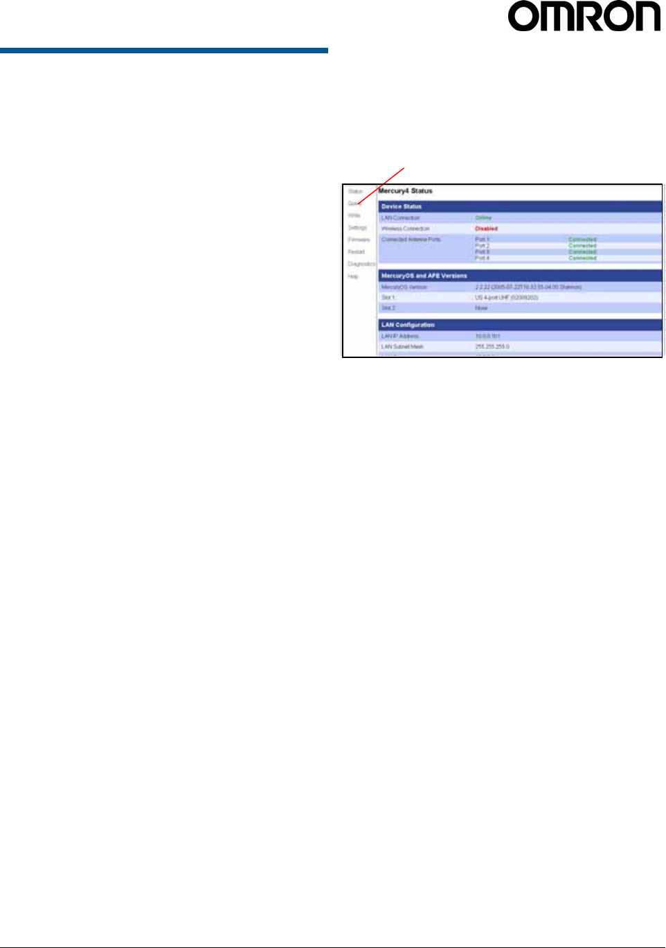
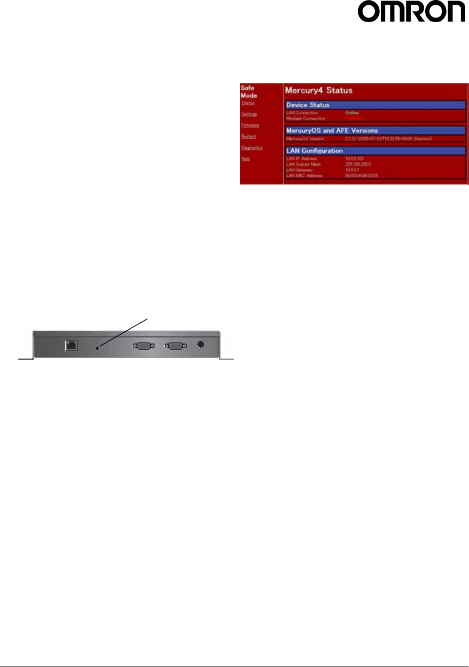
Status Page
The Status page indicates the connected antennas,
software version and LAN configuration of the reader.
IMPORTANT: Check to see that at least one antenna
port is connected before performing any tag queries or
tag write operations.
1. Click the Status link in the navigation menu to
display the Status page.
2. Close the browser window if you are finished
using the browser-based interface.
Note: The status of 'Connected Antenna Ports' is
displayed as 'Connected' only for the antennas
connected to the V740 reader when it starts up.
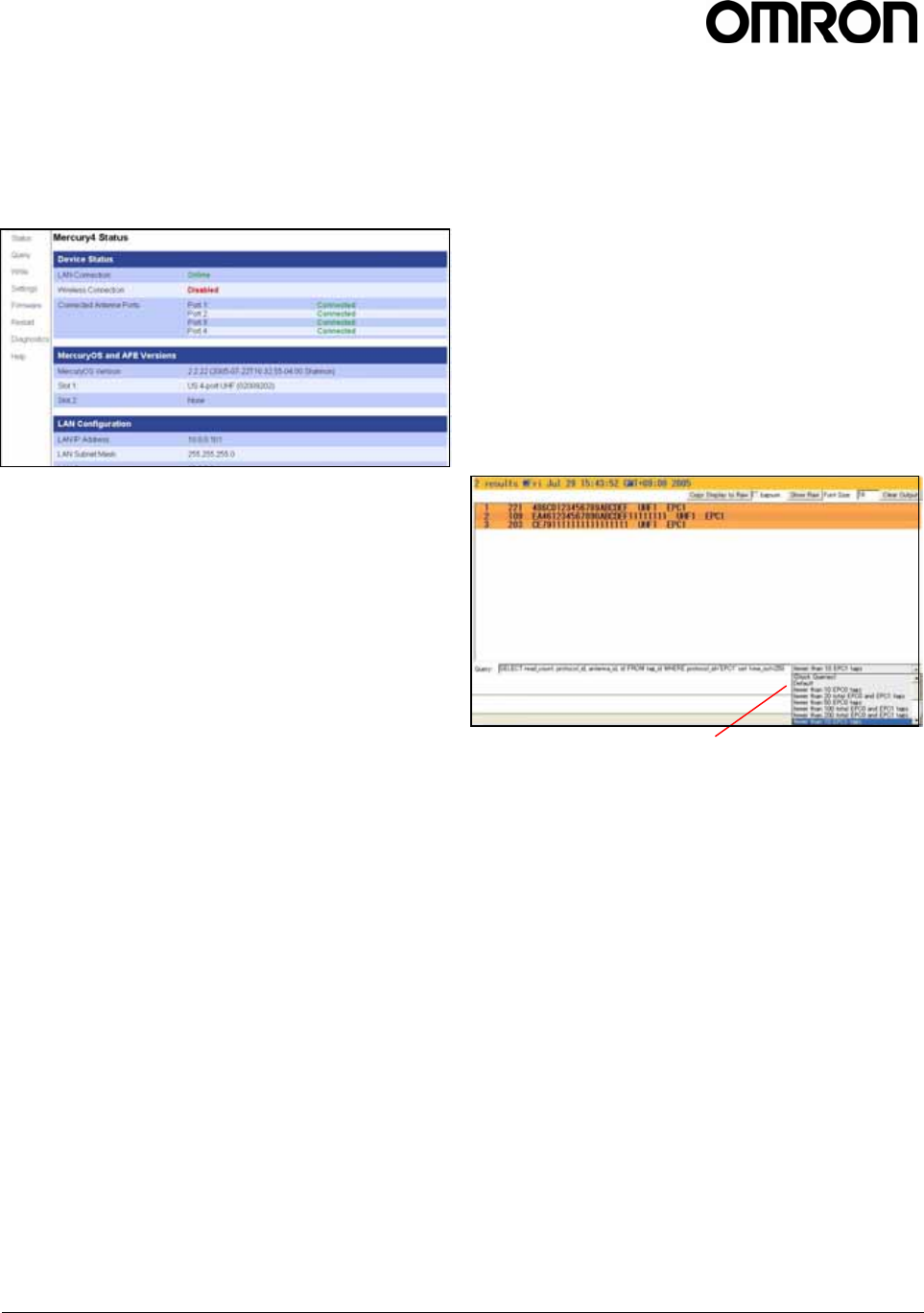
Query Page
The Query page is mainly used to set up and run anti-
collision searches quickly and gives you immediate
feedback, which can be useful for verifying
performance when installation is complete and for
debugging.
At the bottom of the screen is the Query field in which
RQL search statements can be entered or selected
from the stock queries found in the drop-down list to
the right of the Query field. The RQL search statement
in the Query field specifies which tag protocols will be
read, which antenna ports are to be used, how long
the query is to be run, and other read operation
parameters. The query can be run once or
continuously.
Note: The selected settings DO NOT affect reader
performance associated with other applications.
The following stock queries are available from the
drop-down list:
Each mode provides the most suitable time out value
for the protocols and the number of tags to be read.
z fewer than 10 EPC1 tags
z fewer than 50 EPC1 tags
z fewer than 100 EPC1 tags
Note: Only the modes that contain EPC1are
available on this type of V740 reader.
V740 RFID READER/WRITER, ANTENNA 2005-09, REV0.1
OPERATION MANUAL 16 of 56 ©OMRON CORPORATION 2005
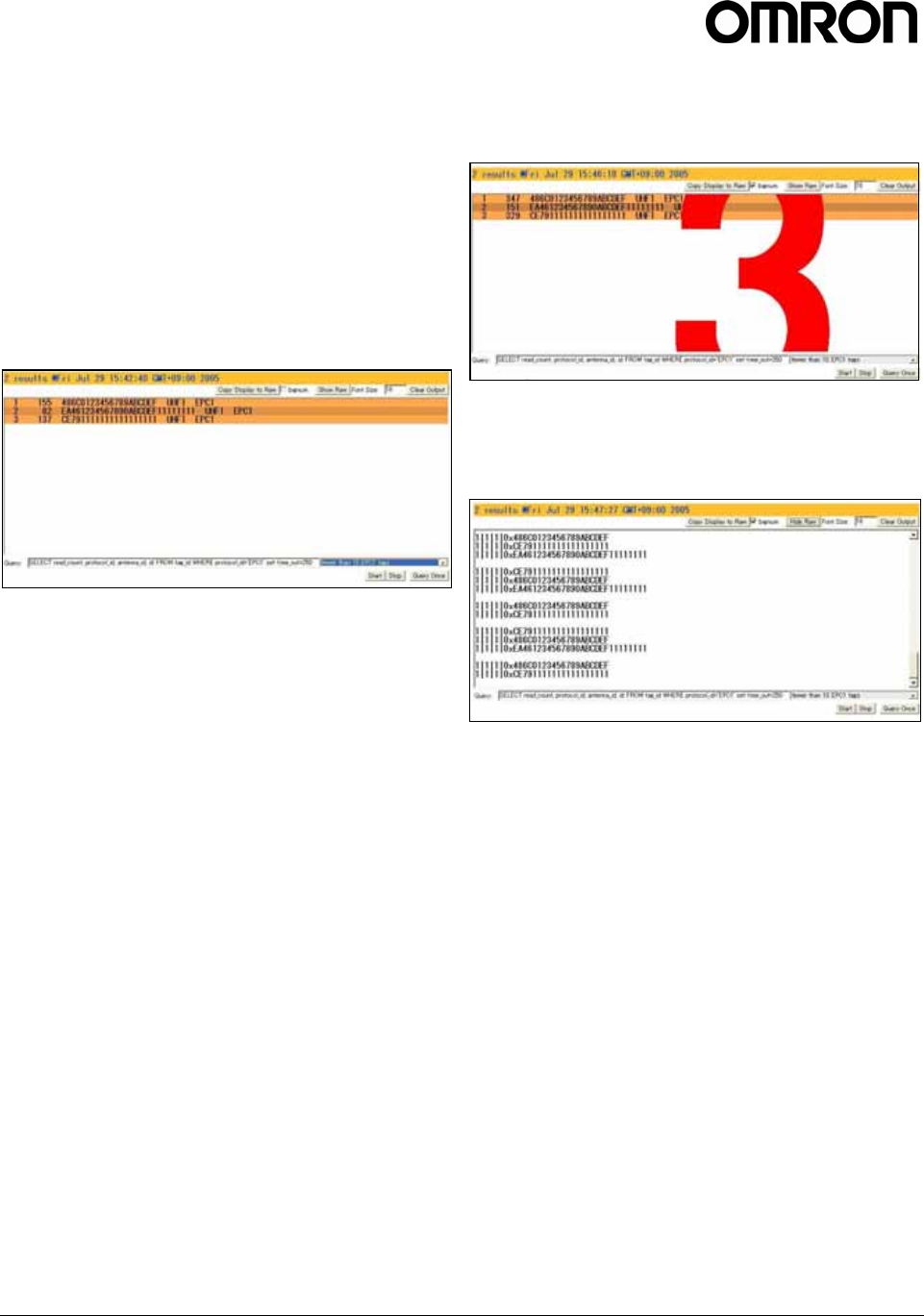
To perform a read operation from the Query
page:
1. Position one or more tags a few feet in front of
one of the antennas connected to the reader.
2. Select a stock query from the pull-down list.
3. Click the Start button to begin continuously
reading tags.
Tag data is displayed. Each row in this example
shows sequential tag number, number of times
tag was read, tag data, antenna, and protocol.
4. Click Stop to stop the tag search.
IMPORTANT: You MUST stop the query before
changing the operating mode or RQL command. If
you do not click STOP before exiting the browser-
based interface, the reader will continue to poll
antennas.
Note: The SELECT clause may be modified.
However changing the SELECT clause may
cause incorrect display of data.
The Query page provides additional options that
enable you to control the data that is gathered and
how it is displayed:
• Copy Display to Raw button enables to copy
data from the colored list screen to raw data mode
that displays raw tag data. This function is
available only when the colored tag list screen is
displayed.
• Bignum checkbox (when checked) displays the
total number of unique tags read. The total is
displayed in large red numbers directly over the
tags read. This function is not available when
Show Raw screen is displayed.
• Show Raw button displays raw tag data on the
Query page. Each row in this example shows read
count, protocol, antenna, and tag data.
• Hide Raw button stops the display of raw tag data.
• Font Size text box decides the character size of
tags read list. It can be applied from 1 to 128.
• Clear Output button clears the tags read list
displayed.
• Query Once button initiates a single search cycle.

V740 RFID READER/WRITER, ANTENNA 2005-09, REV0.1
OPERATION MANUAL 17 of 56 ©OMRON CORPORATION 2005
Write Page
Use the Write page to replace the id or data that is
encoded on a tag.
Consider the following guidelines when writing to tags:
• Always place a tag 0.3–0.6m (1–2ft) from the
antenna when writing data. The tag may be
damaged if it is too close to the antenna.
• Only unlocked tags can be written.
• The id or data to be written must match exactly
the number of hexadecimal characters (numerals
from 0-9 and letters from A-F) specified by the
tag’s protocol. For example: 64-bit EPC1 tag ids
are 16 hexadecimal characters long.
• To write one tag, place the tag in the antenna field.
If multiple tags are present, they will all be
encoded with the same EPC data.
• Use the antenna connected to port 1 of the reader
To write ids or data to a tag:
1. Click the Write link on the navigation menu. The
Write page appears.
2. In the middle pane, type or paste a hexadecimal
tag id to be written to the tag in the RQL
statement after tag_id=0x. ( For example: 16 hex
characters for 64-bit tags, 24 characters for 96-bit
tags, etc.)
3. Select the checkbox for EPC1.
4. Click the Make Update button. A query designed
to write the highlighted data to the tag appears in
the center pane.
5. Place the tag 0.3–0.6m (1–2ft) from the antenna
connected to the port 1.
Verify that no other tags are in the antenna’s field.
6. Click the Submit Query button to write the data. If
the write was successful, the new tag id appears
in the bottom pane.
If the write is not successful, the response will
include an error message.
To read data from a tag:
1. Display the Write page (click the Write link on the
navigation menu).
2. Click the Make Select button. A query designed
to read data from the antenna connected to the
port 1 appears in the center pane.
3. Place the tag to be read within the detection zone
of the antenna.
4. Click the Submit Query button to read tag data.
Query results appear in the bottom pane.
V740 RFID READER/WRITER, ANTENNA 2005-09, REV0.1
OPERATION MANUAL 18 of 56 ©OMRON CORPORATION 2005
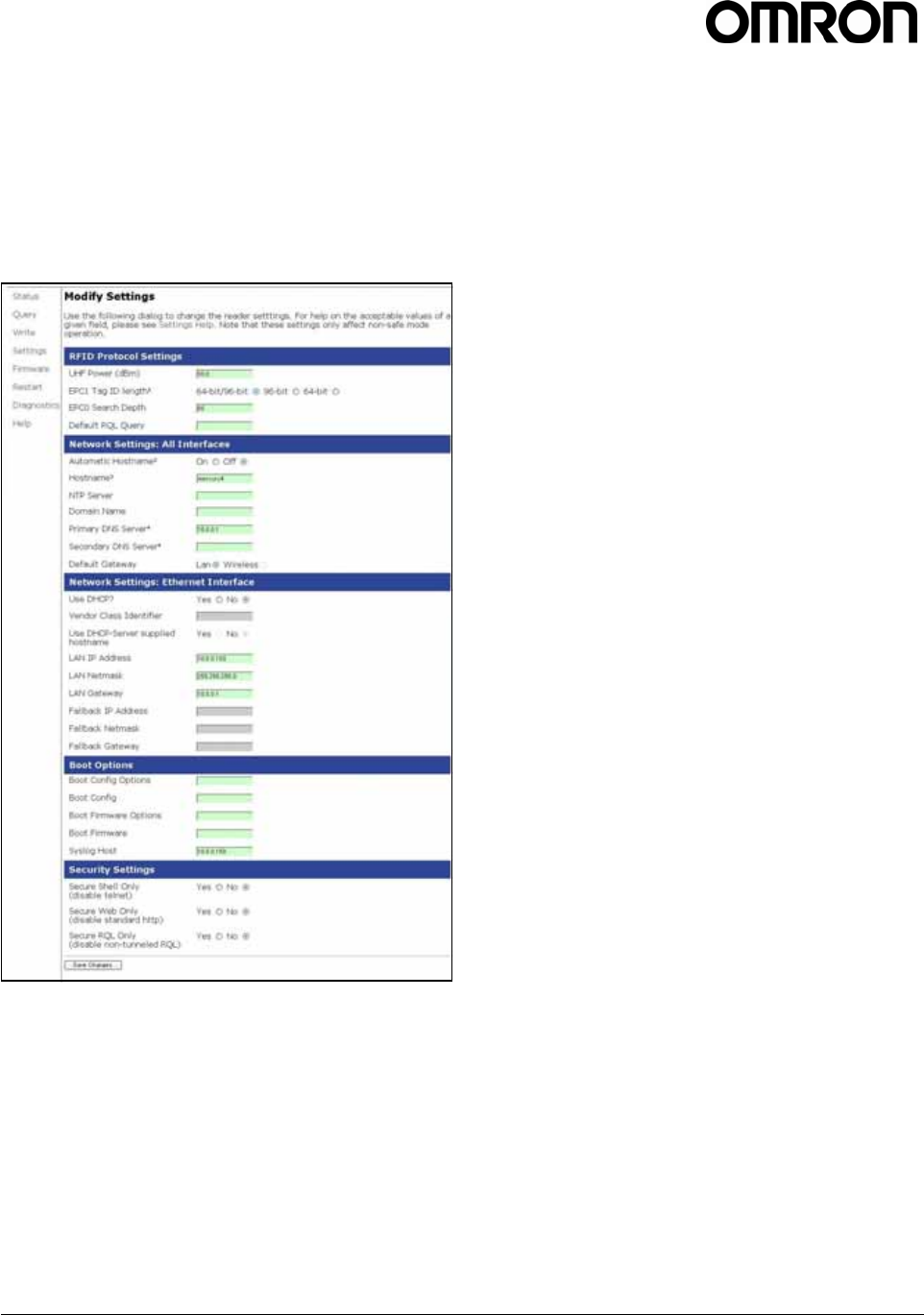
Settings Page
Use the Modify Settings page to change RFID
protocol, network and reader security settings. The
page is divided into five sections: RFID Protocol
Settings; Network Settings: All Interfaces; Network
Settings: Ethernet Interface; Boot Options and
Security Settings.Instructions for Modifying the
Settings.
1. Click the Settings link on the navigation menu.
The Modify Settings page appears.
2. Enter the required settings.
3. Click the Save Changes button to save the new
settings.
IMPORTANT: Do not disconnect power until the
save process is complete.
(see 1.5.2 Restarting the Reader on page 25).
Instructions for Modifying the Settings
Changing these parameters changes the reader’s
settings used on startup. RFID protocol settings, boot
options and network settings can be modified. Care
must be taken to use correct values or you might be
unable to connect the reader without restarting into
safe mode.
IMPORTANT: Do not disconnect power until the save
process is complete.
Static network settings are ignored when in DHCP
mode, and DHCP related settings are ignored when in
static IP mode. Please note that your network needs
to have properly configured DNS servers if you wish
to connect to the reader via its hostname. Usually
when using DHCP, the DHCP server will add the
hostname to the DNS server’s database.
The reader adjusts time by NTP only once when it
starts up. You should confirm if the time is correct
using Get information command (Ref. Section
2.2.4.4).
Note that new RFID, network and security settings
take effect after saving. Boot-related options are
saved but DO NOT take effect until the reader is
restarted. Therefore, to ensure that all new settings
take effect, it is recommended that you restart the
reader whenever reconfiguring and after saving the
new settings.
Note: Please ask the network administrator about the
network settings in your environment.

V740 RFID READER/WRITER, ANTENNA 2005-09, REV0.1
OPERATION MANUAL 19 of 56 ©OMRON CORPORATION 2005
RFID Protocol Settings
The RFID protocol settings take effect immediately on the reader upon saving them. A restart is not required.
The Default RQL Query runs continuously at startup and thus a change to this setting requires a restart of the
reader.
Item Describe Setting
Requirement Default
UHF Power
(dBm)
UHF Output power in dBm. This setting must be adjusted
carefully to comply with FCC regulations. Mandatory 30.0
EPC1 Tag ID
length
Radio buttons that enable combined 96- and 64-bit tag
support or single tag id lengths. If the reader will only be
reading 96- or 64-bit tags, select that radio button to
optimize read rates.
Optional 64-bit/96-bit
EPC0 Search
Depth
Maximum number of EPC0 tags to be singulated on each
query.
(This function is not available as this type of the V740
reader does not support EPC0 protocol.)
Optional 80
Default RQL
Query
Initial query to be run continuously when reader starts up.
The most recent command entered is performed
automatically and continuously every second after
rebooting the reader.
Once a user program has connected to port 8080, the
results of the command will be available.
Optional (none)

V740 RFID READER/WRITER, ANTENNA 2005-09, REV0.1
OPERATION MANUAL 20 of 56 ©OMRON CORPORATION 2005
Network Settings: All Interfaces
Static network settings are ignored when in DHCP mode, and DHCP related settings are ignored when in static
IP mode. Please note that your network needs to have properly configured DNS servers if you wish to connect
to the reader via its hostname. Usually when using DHCP, the DHCP server will add the hostname to the DNS
server’s database.
Item Describe Setting
Requirement Default
Automatic
Hostname
Turning on automatic hostname will append the last six
numbers (3 bytes) of the reader’s MAC address to the text
in the hostname field.
With the unique hostname, avoid the same hostname
existing in the network, which may occur while some
readers are operating simultaneously in DHCP mode.
Optional No
Hostname Specify a name that is unique on the network for the
reader. Mandatory v740
NTP Server Specify the IP address (or machine name) of the server to
get current time from the network (either LAN or WAN). The
reader obtains the correct time from another device since it
doesn't have a hardware clock.
Example) 129.6.15.8(NIST, Gaithersburg, Maryland)
Optional (none)
Domain Name Specify the group name when using devices on the network
as a group. Omit unless using devices as a group. Optional (none)
Primary
DNS Server
Specify the IP address (or machine name) of the server
that replaces a domain name with an IP address on the
network. It is used first, the secondary DNS server is used
next. Omit if you access by the static IP address.
Optional 10.0.0.1
Secondary
DNS Server
Specify the IP address (or machine name) of the server
that replaces a domain name with an ID address. The
server is used only when the primary DNS server can not
find the domain name. Omit if you access by the static IP
address.
Optional (none)
Default Gateway Select whether the reader uses LAN wired or air interface. - LAN(fixed)

V740 RFID READER/WRITER, ANTENNA 2005-09, REV0.1
OPERATION MANUAL 21 of 56 ©OMRON CORPORATION 2005
Network Settings: Ethernet Interfaces
Item Describe Setting
Requirement Default
Use DHCP Select whether the reader gets an IP address on the
network automatically by DHCP or manual setting. You
must not check the item if you use a manually set IP
address.
Optional Yes
Vendor Class
Identifier
Specify an extra DHCP parameter for integration and
customization. It is not supported on the firmware version
2.2.22.
Optional mercury4
Use DHCP
Server Supplied
Hostname
Set this to yes to allow the DHCP server to assign the
reader a hostname. - No
LAN IP Address Specify a unique IP address on the network when manually
set. It is given automatically by the DHCP server, if using
DHCP.
Mandatory (in
the case of not
using DHCP)
10.0.0.101
LAN Netmask Specify the mask value to determine the network address
of the subnet from the IP address. It is not used if using
DHCP.
Mandatory (in
the case of not
using DHCP)
255.255.255.0
LAN Gateway Specify a unique IP address for the gateway machine only
when communicating with the device on another LAN. You
don't have to set the item when communicating with the
device on the same LAN. Also It is not used if using DHCP.
Optional (in the
case of not using
DHCP)
10.0.0.1
Fallback IP
Address
IP address to be used If any DHCP server can't be found
when in DHCP mode. Optional (in the
case of using
DHCP)
(none)
Fallback
Netmask
Subnet mask to be used if any DHCP server can't be found
when in DHCP mode. Optional (in the
case of using
DHCP)
(none)
Fallback
Gateway
Default gateway to be used If DHCP server can't be found
when in DHCP mode. Optional (in the
case of using
DHCP)
(none)

V740 RFID READER/WRITER, ANTENNA 2005-09, REV0.1
OPERATION MANUAL 22 of 56 ©OMRON CORPORATION 2005
Boot Options
The boot option settings specify the location of downloadable firmware and configuration files and their optional
parameters, and the location of a syslog server to which all reader events may be sent.
Item Describe Setting
Requirement Default
Boot Config
Options
Optional parameters used when downloading a new
configuration file to the reader. It is not supported on the
firmware version 2.2.22.
Optional (none)
Boot Config URI to the tm.conf file to be downloaded on startup. Specify
local:default for local tm.config file. It is not supported on
the firmware version 2.2.22.
Optional (none)
Boot Firmware
Options
Same as Boot Config Options used when downloading new
firmware to the reader.
Following four parameters are available as a user
specifiable option.
-f / --force Force a downgrade if config file
version is lower than that currently
running on the reader.
-w / --wipe Wipe flash memory and settings
-p / --preserve Preserve configuration settings under
a wipe.
-a / --auto Add the reader’s MAC address to
download filename.
Optional (none)
Boot Firmware URI to the firmware file to be downloaded at startup. Optional (none)
Syslog Host Name of host for remote logging. All log levels in syslog will
be sent to this host. Syslog message includes information
of events occurring in V740 reader as below.
(a) Boot message
(b) Query page display and query performance
(c) Log-in by telnet, SSH
(d) Change of setting values
(e) Firmware upgrade
Optional (none)

V740 RFID READER/WRITER, ANTENNA 2005-09, REV0.1
OPERATION MANUAL 23 of 56 ©OMRON CORPORATION 2005
Security Settings
These settings control secure access to the reader using a combination of SSH, HTTPS and secure RQL calls.
Item Describe Setting
Requirement Default
Secure Shell
Only
(disable telnet)
If Yes, the telnet server is disabled, and reader access can
only be performed via a secure shell (SSH). It is
recommended to set 'No' in ordinary use.
Optional No
Secure Web Only
(disable standard
http)
If Yes, reader will only respond to requests using https
URLs. Access via http URLs is disallowed. It is
recommended to set 'No' in ordinary use.
Optional No
Secure RQL Only
(disable non-
tunneled RQL)
If Yes, RQL no longer listens on Port 8080 for remote
access. RQL is still accessible via an SSH tunnel. It is
recommended to set 'No' in ordinary use.
Optional No
V740 RFID READER/WRITER, ANTENNA 2005-09, REV0.1
OPERATION MANUAL 24 of 56 ©OMRON CORPORATION 2005
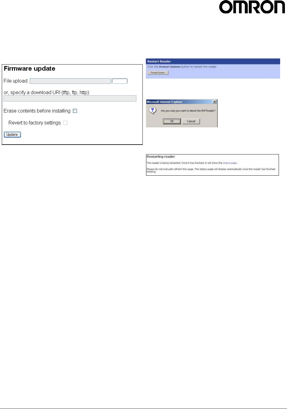
Firmware Upgrade Page
Use the Firmware upgrade page to update firmware.
Only the update firmware file provided by OMRON
can be used.
1. Click the Firmware link on the navigation menu.
The Firmware upgrade page appears.
2. Place the cursor in the Filename field and type
the complete URL network pathname of the
firmware or click the Browse button to locate the
new firmware file.
3. Be sure to click both check boxes if you want the
reader to revert to safe-mode settings (Ref.
section 1.5.3.).
The lower check box becomes enabled after
clicking the check box above.
4. Click the Update button to download the new
firmware to the reader. The status frame at the
bottom of the page displays the progress of the
update.
5. To activate the new firmware, restart the reader.
Until the reader is restarted, the old firmware will
still be active.
In the unlikely event that a firmware update fails,
perhaps due to a power failure, the device will restart
in Safe Mode.
Note: You should not check the check box of 'Erase
contents before installing'. Or the V740 Reader loses
the function of I/O control(See section 3).
If the V740 Reader loses the I/O function, you should
query OMRON to tell the way of recovering the
function.
Restart Page
Use the Restart page to restart the reader.
1. Click the Restart link on the navigation menu. The
Restart Reader page appears.
2. To restart the reader, click the Restart System
button. The following dialog box appears.
3. Click OK. The following message appears and
remains on the screen until the reader restarts.
Then the Status page appears.
Browse
V740 RFID READER/WRITER, ANTENNA 2005-09, REV0.1
OPERATION MANUAL 25 of 56 ©OMRON CORPORATION 2005
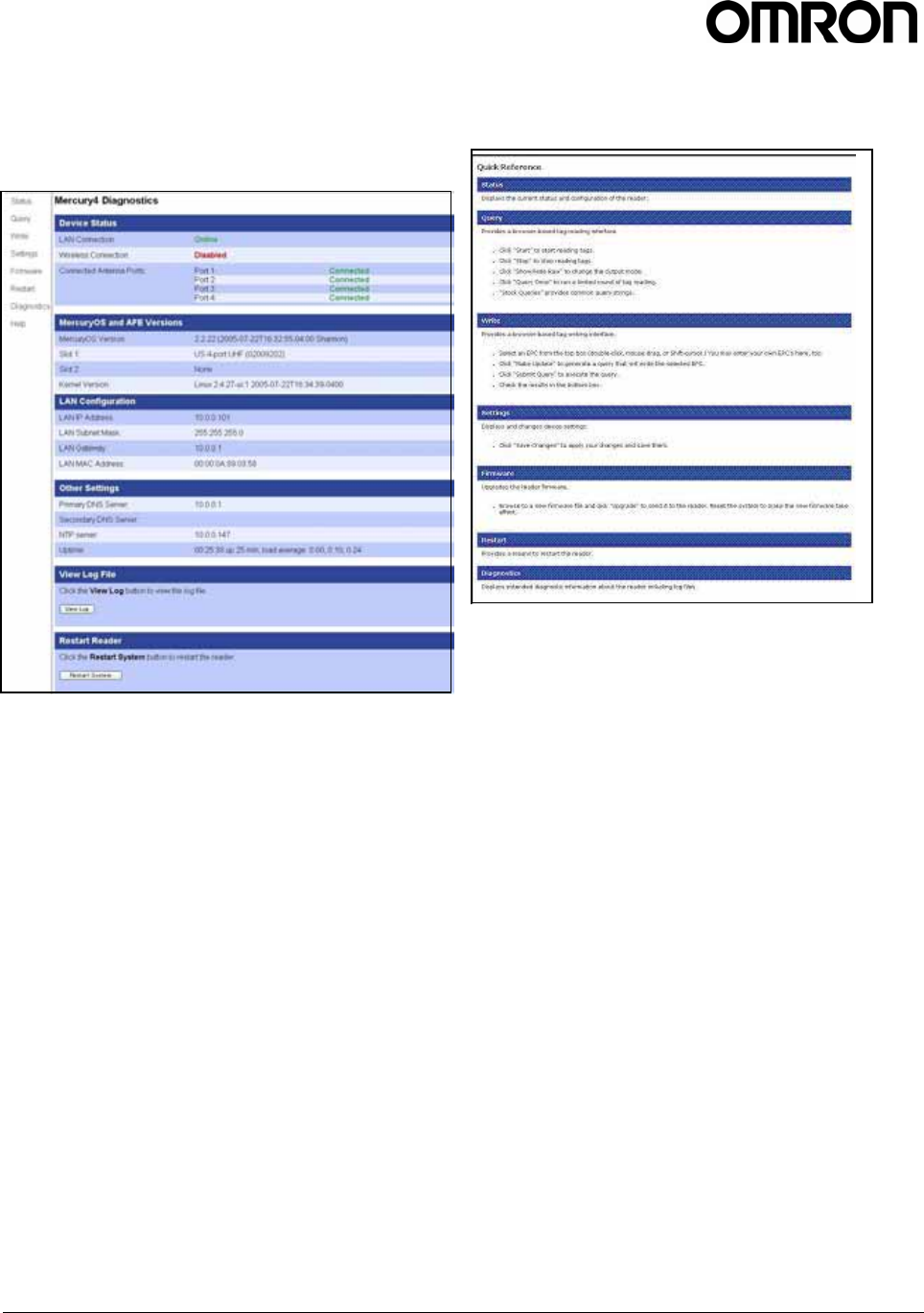
Diagnostics Page
The Diagnostics page provides a wealth of
information, including the current settings of the
reader, comprehensive version information, and
current status of network interfaces.
• View Log is used for maintenance of the reader.
For use by OMRON only.
Help Page
Use the Help page to view descriptions of system
operations.
1.5.2 Restarting the Reader
Use this procedure to recover from a reader error.
1. Click the restart link on the navigation menu.
2. Click the restart button and the OK button on
the confirmation dialog.
Wait for at least 60 seconds for the reader to boot up.
The Power/Heartbeat LED is solid green while the
reader boots. When the LED begins blinking, the boot
process is complete.
V740 RFID READER/WRITER, ANTENNA 2005-09, REV0.1
OPERATION MANUAL 26 of 56 ©OMRON CORPORATION 2005
1.5.3 Using Safe Mode
Use the recessed Safe Mode button on the reader
connector panel to recover from errors which prevent
the reader from operating in normal mode. In Safe
Mode the reader is configured with a static IP address
of 10.0.0.101. Safe mode operation restores factory
default settings as follows:
Firmware Version: factory installed version
IP Address: 10.0.0.101
Host Name: Mercury4
Although the browser-based interface pages are
displayed in red when operating in safe mode, the
reader is still functional, although it cannot read or
write tags. In most cases, the reader will need to be
reconfigured for operation with the reader application
after starting in Safe Mode.
1. 1. With the reader running, hold down the
recessed reset button for 4 seconds, using a non-
conductive object.
2. Release the button
3. The green LED should turn solid as soon as the
button is released, indicating the reader is
rebooting. It should take approximately 30
seconds to boot into Safe Mode. The web server,
telnet server and SSH server run in Safe Mode,
however none of the RFID features are activated.
To communicate with the reader in Safe Mode, a
PC must have an IP address and subnet mask
that are compatible with the reader settings, for
example:
IP address 10.0.0.10
netmask 255.255.255.0
There are two main reasons to enter Safe Mode.
One is to perform a firmware update to repair a
corrupted file system. The second is to change
settings that are preventing the reader from
operating normally.
Both of these tasks can be performed via the web
interface.
4. Once the maintenance has been performed,
restart the reader to activate the changes.
Disconnect power from the reader.
Reset button
V740 RFID READER/WRITER, ANTENNA 2005-09, REV0.1
OPERATION MANUAL 27 of 56 ©OMRON CORPORATION 2005
1.6 Tag Fundamentals
Tag Memory Structure
Protocols and the tag memory structures supported by
the V740 reader are described below. For additional
information regarding tag operation, refer to each tag
specification.
Class 1 Tags
Class 1 tags contain 96 bits of programmable memory.
It consists of EPC Code, Check Code data. 64 bits of
them are EPC Code, and the first 16 bits of them are
Check Code for the EPC Code.
Byte Bit Contents
1 0-7
2 8-15
3 16-23
4 24-31
5 32-39
6 40-47
7 48-55
8 56-63
9 64-71
10 72-79
Class 1B Tags
Class 1B tags contain 128 bits of programmable
memory. The format is almost the same as the Class
1 tags. Bit count of EPC code is 96.
Byte Bit Contents
1 0-7
2 8-15
3 16-23
4 24-31
5 32-39
6 40-47
7 48-55
8 56-63
9 64-71
10 72-79
11 80-87
12 88-95
13 96-103
14 104-111
EPC Code
8bytes (64bits)
Check Code (CRC)
Check Code
(
CRC
)
EPC Code
12bytes (96bits)

V740 RFID READER/WRITER, ANTENNA 2005-09, REV0.1
OPERATION MANUAL 28 of 56 ©OMRON CORPORATION 2005
1.7 Specifications
Electrical
Reader
UHF operating frequency ...................902–928MHz
Input voltage.........................................24Vdc, 2.0A
RF connector type............................. Reverse-TNC
Separate Power Supply
Input voltage.......... Nominal 100–240Vac, 50/60Hz
AC line current...................... Nominal 0.5A at 120V
Output voltage...............Nominal 24Vdc, 2.5A peak
Antenna
Operating frequency...........................902–928MHz
V.S.W.R....................................................... < 1.5 :1
Polarization................................................. Circular
Impedance.....................................................50ohm
Cable length ......................................... 30cm(11.8’)
RF connector type....................................N-Female
Environmental
Reader
Operating temperature: ... 0° to 40°C (32° to 104°F)
Storage temperature: ....-20° to 65°C (-4° to 149°F)
Relative humidity: .... 25 to 85%RH non-condensing
Antenna
Operating temperature: -10° to 55°C (14° to 122°F)
Storage temperature: ..-25° to 65°C (-13° to 149°F)
Relative humidity:.... 25 to 85%RH non-condensing
Mechanical
Reader
Dimension .................................308 X 286 X 40mm
(12.1 X 11.3 X 1.6 in)
Weight ...............................................1.5kg (3.4 lbs)
Protection .........................................................IP40
Antenna
Dimension ..................................496X 221 X 70mm
Weight .............................................................2.0kg
Protection .........................................................IP50
Outline Drawings
See on the page 51 to 52.
Supported Tag Protocols
915 MHz......................................... EPC Class 1/1B

V740 RFID READER/WRITER, ANTENNA 2005-09, REV0.1
OPERATION MANUAL 29 of 56 ©OMRON CORPORATION 2005
2. Query Protocol
Reference Guide
This chapter lays the groundwork for the
communication protocol between client software
running on a remote computer and the V740 reader.
The client software may be a database system,
enterprise software, or user software.
In this chapter, we discuss the underlying transport
protocol used and present the initial communication
protocol RQL. This protocol is loosely based on the
SQL language with extensions for a better notion of
time. This protocol was designed for rapid prototyping
of applications, where a full query to the reader can be
encapsulated in a single line of ASCII text. A simple
polling mechanism exists for automatically receiving
tag event.
2.1 Transport Protocol
In the current implementation, TCP/IP is used as the
transport protocol. TCP is a connection-oriented
protocol that provides a reliable, in-order data
transport layer with end-to-end checksums and flow
control.
2.1.1 TCP Connection Setup and
Teardown
A session between client software and the reader
consists of connection setup, data transactions, and
connection teardown.
At present, all connections are initiated only by the
client software. If, for example, the reader is
configured to automatically forward events and/or data
to the client software but the client software has not
established a connection, then no attempt is made by
the reader to contact the client software to establish a
connection. Furthermore, if an extant connection
terminates unexpectedly, the reader will not attempt to
contact the client software to re-establish a connection.
All responsibility for opening, maintaining, and closing
the connection during a session rests with client
software.
The client software sets up a TCP socket connection
on reader port 8080. After connecting successfully,
communication between the client software and the
reader can proceed as described below. Once the
client software has determined that communication
has concluded, the connection must be terminated at
the TCP level. In order to prevent synchronization
issues, each reader will support only one TCP
connection.
Other transport protocols may be used to
communicate between the client software and its
subjugate readers. The application-level protocol
discussed below is neutral with respect to the
transport layer.
V740 RFID READER/WRITER, ANTENNA 2005-09, REV0.1
OPERATION MANUAL 30 of 56 ©OMRON CORPORATION 2005
2.2 Event/Query Protocol
The client software can control the reader using RQL
via TCP connection and can acquire data from the
readers in two modes: 1) by requesting specific data
or 2) by automatically receiving events. The two
modes are discussed in further detail in the following
subsections.
In order to keep the protocol comprehensive and easy
to use, we specify a small set of commands that allow
the client software to fully configure the readers and
exploit their capabilities.
This minimal set of commands includes the ability to
request reads based on several relevant criteria (for
example, group reads, range reads, reads by prefix,
and so on). The ability to reset the reader database
and other control capabilities are also provided for.
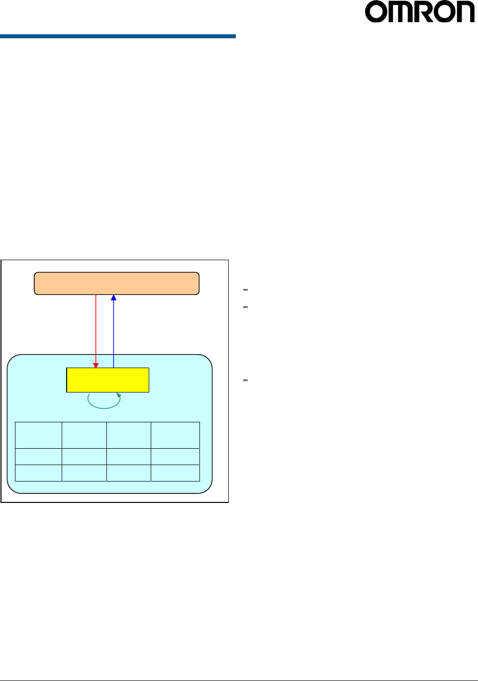
Figure 1 : Conceptual diagram of control flow
2.2.1 Client Software
Requests/Functionality
The client software is able to make the following
requests of a reader:
• Read IDs of all tags within range of all antennas.
• Read IDs of all tags within range of a given
antenna.
• Read IDs of all tags within a certain subset of tag
IDs within range of all antennas.
• Read IDs of all tags within a certain subset of tag
IDs within range of a specific antenna.
• Read Individual tag IDs within range of a certain
antenna or all antennas.
• Read only the IDs of tags communicating a given
RF communication protocol.
• Return the number of times a given tag was read
per query.
• Write IDs to a tag.
• Register any commands as aliases (cursor) to the
V740 reader.
• Execute any aliases (cursor) one time
• Execute any aliases (cursor) repeatedly at the
indicated interval.
• Execute any aliases (cursor) repeatedly in the
specified term.
Client PC
V740 Reader/Writer
RQL Engine
1. Query
id
protocol_id
antenna_id
read_count
3. Reply
0x1234
EPC1
2
1
2. Tag population/general query is made
id protocol
id antenna
id read
count
0x1234 EPC1 2 1
0xABCD EPC1 1 2
0xABCD
EPC1
1
2
V740 RFID READER/WRITER, ANTENNA 2005-09, REV0.1
OPERATION MANUAL 31 of 56 ©OMRON CORPORATION 2005
2.2.2 General Observations,
Commands, and Syntax
We note that a reader behaves very much like
database wherein each individual tag represents an
entry in the database with a given set of attributes.
Due to memory constraints of the reader, the system
will remove entries from the database as they are
queried.
The syntax for querying against this database is
derived from SQL syntax.
In the simplest case, the client software explicitly
requests data by polling the readers. The request
protocol is implemented in such a way that the client
software specifies:
Required information.
• What subset of tags the reader should consider.
• Which read constraints should be applied.
Example commands:
• SELECT id FROM tag_id WHERE
id=0x1234567890ABCDEF AND antenna_id=1 AND
protocol_id='EPC1';
Would return a tag only if its tag ID was
0x1234567890ABCDEF.
• SELECT id FROM tag_id WHERE (antenna_id=1
OR antenna_id=2) AND protocol_id='EPC1'
SET time_out=1000;
Would return a tag only if the antenna ID was 1 or
2 and will search for at least 1000ms.
Note: The RQL command is terminated by a
semicolon. When you use sample commands in this
manual, you must input a command in one line
without line feed characters.
2.2.3 Extended RQL Command
Structure supported by the V740
Reader
Extended Command Set for Data and Write,
and Lock operations
ID Read : Identify tags, including anti-collision.
ID Write : Change tag ID
ID Lock : Prevent further changes of tag ID
Kill : Initialize tag
Password : Set a pass-code to kill a tag
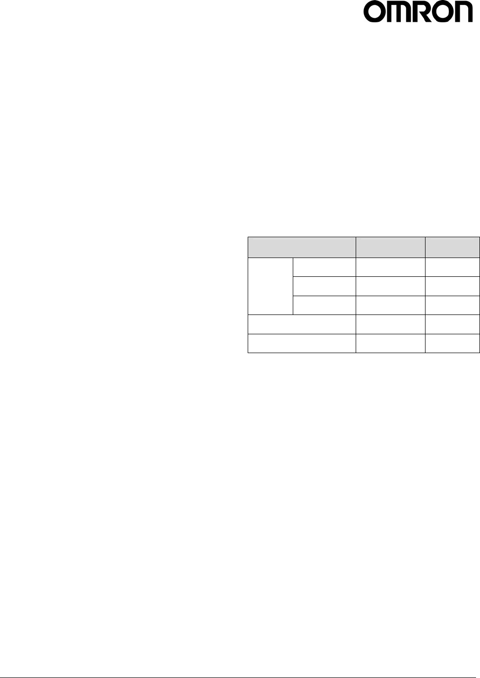
Table1: Supported Protocols for each function
With the exception of the ‘ID Read’ command, all
commands are protocol and antenna specific and can
only be used with a single protocol at a time and with
a single antenna at a time. Hence all queries with the
exception ‘ID Read’ need to be constrained to one
protocol and one antenna, for example
WHERE protocol_id='EPC1' and
antenna_id=1
A complete example of an ‘ID Write’ query would be
UPDATE tag_id SET
id=0x0123456789ABCDEF WHERE
protocol_id='EPC1' AND antenna_id=1.
‘ID Read’ (enumerate tags) is, by definition, a multi-
target command, since it determines what the
individual targets are in the first place.
There are some special cases to the single-target rule.
For example, ID Write is semantically tricky – what
does it mean to target a tag if its target ID is going to
be changing? In the current state of the art, most
protocols do not support addressed ID writes (ID write
targets all tag IDs) or disallow tag ID changes entirely.
Function EPC1 EPC1B
Read ○ ○
Write ○ ○
ID
Lock ○ ○
Kill ○ ○
Password ○ ○

V740 RFID READER/WRITER, ANTENNA 2005-09, REV0.1
OPERATION MANUAL 32 of 56 ©OMRON CORPORATION 2005
2.2.4 Detailed Command Structure
2.2.4.1 ID Read
The client software would use the SELECT command
to read IDs of tags. The SELECT command is for
querying the tag population of the reader as well as
static variables such as firmware version. The
structure of a SELECT command is as follows:
SELECT entry_list FROM
table_expression where_specification
[set_specification];
Ref. Table 2 for entry_list details.
A SELECT clause is entered as:
SELECT entry1, entry2, entry3, ...
one or more entries can be specified, for multiple
entries, a comma delimiter is required.
A table_expression is specified by only one table
name.
FROM table
In the function ID Read, you always use 'tag_id' as a
table name. And so the table_expression is as
follows:
FROM tag_id
A where_specification is entered as:
WHERE boolean_expression
boolean_expression can consist of any expression
which evaluates to a boolean value. In many cases,
this expression will be:
entry binary_operator value
where binary_operator can be one of =, <, <=, >, >= ,
<>, AND, or OR. Parentheses may also be used to
create associations of subexpressions. In the
presence of a 'where_specification', SELECT will not
return any rows for which the WHERE condition does
not evaluate to TRUE.
Note: You must specify one protocol in
'where_specification'.
A set_specification is entered as:
SET expression
expression consists of entry and the value.
In response, all IDs delimitted by LF code are sent.
The format is as follows:
[id1] <LF> [id2] <LF>.....[idn] <LF><LF>
The response includes the check code and ID. The
first 4 digits are the check code, and the ID follows for
the EPC1/1B protocols.
Below are some examples for reading tag ID:
• To query a tag on a specific antenna and protocol,
you can specify a specific antenna and protocol in
the 'where_specification':
SELECT id FROM tag_id WHERE
antenna_id=1 AND protocol_id='EPC1';
SELECT id FROM tag_id WHERE
antenna_id=2 AND protocol_id='EPC1';
The first specifies 1 as an antenna id, and EPC1 as a
protocol id. The second specifies 2 as an antenna id,
and EPC1 as a protocol id. The reader searches tags
that corresponds to the condition, and returns the tag
ID if the tag is present followed by LF code, an empty
event (only LF code) results if tags matching the
'where_specification' are not present.
• To query a tag on multiple antennas, you can
specify multiple antennas by 'OR' operator in the
'where_specification':
SELECT id FROM tag_id WHERE
(antenna_id=1 OR antenna_id=2) AND
protocol_id='EPC1';
SELECT id FROM tag_id WHERE
(antenna_id=1 OR antenna_id=2 OR
antenna_id=3 OR antenna_id=4) AND
protocol_id='EPC1';
The first specifies 2 antennas, and the second
specifies 4 antennas.
• To query a specific tag, given its EPC code, one
can specify a specific tag with an ID as a
hexadecimal number:
SELECT id FROM tag_id WHERE
id=0x1234567890ABCDEF AND
antenna_id=1 AND protocol_id='EPC1';
When Indicating id in the 'where_specification',
the reader searches the ID from the higher order.
If the value is shorter than 16 digit for EPC1(24
digit when using EPC1B), it examines only upper
bits.
SELECT id FROM tag_id WHERE
antenna_id=1 AND protocol_id='EPC1' AND
id=0x1234;
• To query a specific sub class of tags, given a
range of tag ID values:
V740 RFID READER/WRITER, ANTENNA 2005-09, REV0.1
OPERATION MANUAL 33 of 56 ©OMRON CORPORATION 2005
SELECT id FROM tag_id WHERE
protocol_id='EPC1' AND antenna_id=1
AND (tag_id>=min_tag_id AND
tag_id<=max_tag_id);
The reader returns the tag ID values for all the
present tags between min_tag_id and
max_tag_id, which are hexadecimal values.
• To query tags by specific or all antennas:
SELECT id FROM tag_id WHERE
antenna_id=1 AND protocol_id='EPC1';
SELECT id FROM tag_id WHERE
protocol_id='EPC1';
At the first, the reader searches tags only by
antenna 1. Second the reader searches tags by
all antennas available. Omitting the antenna
indication in the 'where_specification' means to
search all antennas available.
Note: When specifying multiple antennas even if
an antenna that does not exist is specified, the
reader obtains the tag ID only using antenna 1
and doesn't return any an error message.
SELECT id FROM tag_id WHERE
(antenna_id=1 OR antenna_id=5) AND
protocol_id='EPC1';
• The client software can specify multiple entries in
the select_list field of the SELECT command:
SELECT id, antenna_id FROM tag_id
WHERE antenna_id=1 AND
protocol_id='EPC1';
SELECT protocol_id, timestamp, id,
antenna_id FROM tag_id WHERE
antenna_id=1 AND protocol_id='EPC1';
The first example returns the tag IDs and
antenna_ids, and the second returns protocol_ids
and the time that the tag was read (seconds from
the unix epoch, Jan 1, 1970) with the tag IDs and
antennas_ids.
Note: To read timestamp, the NTP sever must be
set up in advance.
The reader returns protocol_id as an integer value.
The value '1' represents 'EPC1'. For example, the
query with protocol_id and the response is as
follows:
[Query] SELECT protocol_id, id FROM
tag_id WHERE antenna_id=1 AND
protocol_id='EPC1';
[Res] 1|0xCE791111111111111111<LF><LF>
• To query during a specific time:
SELECT id FROM tag_id WHERE
antenna_id=1 AND protocol_id='EPC1'
SET time_out=500;
The command imposes a time out constraint of
500ms; i.e., the reader stops reading and returns
all collected data after 500ms. The order in which
specifying arguments are used is irrelevant. The
default timeout is 250ms if none is specified.
It is important to always use a timeout in
specifying a query to achieve optimal performance
for a given application. Detailed information will be
discussed in the next section
Timeout
The client software can impose a time limit on a read
operation, requesting the reader to search only for a
limited time (specified in milliseconds). The reader
may fail to detect some tags if insufficient time is
allocated to the search operation. The time_out is the
parameter used for specifying the time allocated for
the read operation.
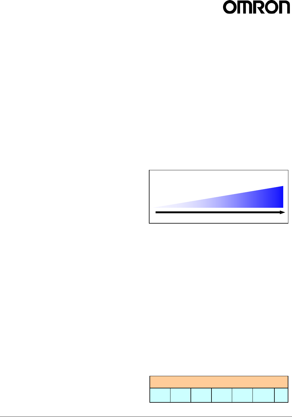
In general, a large time_out should be used for dock
stations (>2000ms), and short time_outs should be
used for conveyor belts (<100ms).
SELECT id FROM tag_id WHERE antenna_id=1
AND protocol_id='EPC1' SET
time_out=1000;
(See 3.2 Communications Time)
The constraints on the scheduler in the reader for the
time_out are shown below. The reader searches
sequentially for each antenna in the time. When the
last antenna completes searching, the reader returns
to the first antenna again. Following chart shows an
example of time schedule given by the model
command as below.
SELECT id FROM tag_id WHERE
(protocol_id='protocol1') and
(antenna_id=ant1 or antenna_id=ant2 or
antenna_id=ant3 or antenna_id=ant3);
short long
time out
Application
Conveyor Dock
Station
time_out
ant1 ant2 ant3 ant4 ant1 ant2 ...

V740 RFID READER/WRITER, ANTENNA 2005-09, REV0.1
OPERATION MANUAL 34 of 56 ©OMRON CORPORATION 2005
The antenna arbitration algorithm is optimized to
maximize the read rate of all the tags in the field. The
time division for each antenna is determined
automatically by the reader and cannot be specified
by the user.
e.g. if 10 EPC1 tags takes 20 ms per tag on
average. With two antennas:
minimum time_out =
10 x 20 x 2 x 2 = 800 ms.
Note: It is caused by the following reasons that the
difference between the time_out value and actual time
required for reading.
It spends 20 ms to switch protocols.
The max of the difference can be calculated by
summing up the time caused by the reasons. You
need consider time lag to avoid mutual interface due
to time sharing.

V740 RFID READER/WRITER, ANTENNA 2005-09, REV0.1
OPERATION MANUAL 35 of 56 ©OMRON CORPORATION 2005
Table 2:
Reader Internal Tag Data Table Schema -Tag Read
Keyword Entry Table Arguments Range Example
Value Comments
id tag_id Hex String - 0xFEDCBA0
987654321
Requests the id (tag
data) of the tag
antenna_id tag_id Int - 2 Requests the antenna
id used to read the
tag
protocol_id tag_id Int - 1 (EPC1/1B)
Requests the protocol
id of the tag
read_count
(*1)
tag_id Int - 1 Requests the number
of times a tag ID was
read
SELECT
timestamp tag_id String - 1101973245.
003590
Requests the time M4
read data from the
tag.
To get the correct
time, you need to
adjust the clock by
setting NTP server.
FROM tag_id - - - - The name of the
internal tag data
table(fixed)
antenna_id tag_id Int [1...4] 1 Specifies the antenna
used to read a tag
protocol_id tag_id String 'EPC1' 'EPC1' Specifies the protocol
used to read a tag.
Must be uppercase.
read_count tag_id Int 1 and over 2 Specifies the number
of times a tag was
read
WHERE
id tag_id Hex String - 0xFEDCBA0
987654321
Specifies the tag id to
be read.
SET time_out tag_id Int [1...65535] 500 Specifies the amount
of time the SELECT
command will read
tags in milliseconds.
Note(*1): If you specify 'read_count' on 'EPC1' protocol, the reader returns '1' due to the search algorithm.

V740 RFID READER/WRITER, ANTENNA 2005-09, REV0.1
OPERATION MANUAL 36 of 56 ©OMRON CORPORATION 2005
2.2.4.2 ID Write – Writing data to tag
The UPDATE command is used to write new data
to a tag. The structure of an UPDATE command is
as follows:
UPDATE table_expression set_specification
where_specification;
table_expression and entries specified in
set_specification are provided in Table 3.
A table_expression is specified by only one table
name:
UPDATE tag_id
A set_specification is entered as:
SET entry=value
A where_specification is entered as:
WHERE boolean_expr
In a where_specification, both protocol_id and
antenna_id must be specified.
The tag_id (tag data) is returned with a check code
as follows:
EPC1:[check_code][tag_id]<LF><LF>
The 'where_specification' is specified in the same
manner as the SELECT in the previous section.:
• Example : To write tag data(tag_id) to a 64-bit
EPC tag:
UPDATE tag_id SET id=0x1234567890ABCDEF
WHERE protocol=’EPC1’ AND antenna_id=1;
The reader returns the tag_id if the write
operation was successful.For example the
response is as follows:
0xCE851234567890ABCDEF<LF><LF>
In this case, “CE85” is the check code.
“1234567890ABCDEF” is tag data(tag id).
If the operation failed, "Error 0102: Error
performing query<LF><LF>" returned.
Note: The format of the tag data in the command
must much the selected protocol or an error will
result.
For example :
- A 64 bit EPC1 tag requires 16 hexadecimal digits
- A 96 bit EPC1 tag requires 24 hexadecimal digits
(See section 1.6)
If wrong data is written to the tag, the tag may be
unreadable. In this case, write correct tag ID again,
after that, the tag would turn to be readable.
Table3 : Reader Internal Tag Data
Table Schema -Tag Write
Keyword Entry Table Arguments Range Example
Value Comments
UPDATE tag_id - - - - The name of the
internal tag data
table(fixed)
SET id tag_id Hex String - 0xFEDCB
A0987654
321
Specifies the tag
id(tag data) to be
written
antenna_id tag_id Int [1...4] 1 Specifies the
antenna used to
read a tag
WHERE
protocol_id tag_id String 'EPC1' 'EPC1'
Specifies the
protocol used to
read a tag.
Must be uppercase.

V740 RFID READER/WRITER, ANTENNA 2005-09, REV0.1
OPERATION MANUAL 37 of 56 ©OMRON CORPORATION 2005
1. ID Lock
The UPDATE command is also used to lock
data of a tag. This can be used to write '1' to
'locked' flag . The structure of an UPDATE
command is the same as ID Write.
• Example : To lock tag id of a 64-bit EPC tag:
UPDATE tag_id SET locked=1,
id=0x1234567890ABCDEF WHERE
protocol=’EPC1’ AND antenna_id=1;
The reader returns the tag_id if the lock
operation was successful. For example the
response is as follows:
|0xCE851234567890ABCDEF<LF><LF>
In this case, “CE85” is the check code.
“1234567890ABCDEF” is tag data(tag id).
If the operation is failed, "Error 0102: Error
performing query<LF><LF>" returned.
• Example : To lock tag id of a 96-bit EPC tag:
UPDATE tag_id SET locked=1,
id=0x1234567890ABCDEF12345678 WHERE
protocol=’EPC1’ AND antenna_id=1;
The reader returns the tag_id the same way as 64-
bit tag.
Note: The format of the tag data in the command
must much the selected protocol or an error will
result. (See section 1.6)
For example :
- A 64 bit EPC1 tag requires 16 hexadecimal digits
- A 96 bit EPC1 tag requires 24 hexadecimal digits
Note: You must send this command to only one tag
at one time in the stable communication area.
Note: Response data always contains a separator in
front of the tag ID.
Note: If the response of the command is different
from the ID of the tag in the communication area,
you need to retry it.
Table4 : Table Schema - Tag Lock
Keyword Entry Table Arguments Range Example
Value Comments
UPDATE tag_id - - - - Tag id database
table (Fixed)
locked tag_id Int 1 1
Can be specified
with only “1”(Fixed).
SET
id tag_id Hex String - 0xFEDCB
A0987654
321
Specifies the tag id
to be updated
antenna_id tag_id Int [1...4] 1 Specifies the
antenna used to
update a tag
WHERE
protocol_id tag_id String 'EPC1' 'EPC1'
Specifies the
protocol used to
update a tag.
Must be uppercase.

V740 RFID READER/WRITER, ANTENNA 2005-09, REV0.1
OPERATION MANUAL 38 of 56 ©OMRON CORPORATION 2005
2. Kill
The UPDATE command is also used to initialize
a tag. 3 parameters must be specified in SET
Clause. The first is 'killed' flag, the second is
password for the tag and the last is id of the tag.
The structure of an UPDATE command is the
same as ID Write.
• Example : To lock tag id of a 64-bit EPC tag:
UPDATE tag_id SET killed=1,
password=0x88, id=0x1234567890ABCDEF
WHERE protocol=’EPC1’ AND antenna_id=1;
The reader returns the tag_id if the kill operation
was successful. For example the response is as
follows:
||0x00000000000000000000<LF><LF>
If succeeded, the response of kill command is all
0.
If the operation is failed, "Error 0102: Error
performing query<LF><LF>" returned.
• Example : To lock tag id of a 96-bit EPC tag:
UPDATE tag_id SET killed=1,password=0x88,
id=0x1234567890ABCDEF12345678 WHERE
protocol=’EPC1’ AND antenna_id=1;
The reader returns the tag_id the same way as 64-
bit tag.
Note: The format of the tag data in the command
must much the selected protocol or an error will
result. (See section 1.6)
For example :
- A 64 bit EPC1 tag requires 16 hexadecimal digits
- A 96 bit EPC1 tag requires 24 hexadecimal digits
Note: You must send this command to only one tag
at one time in the stable communication area.
Note: Response data always contains 2 separators
in front of the tag ID.
Note: After sending this command, you must send
an ID read command and confirm no ID data is sent
as a response.
Table5 : Table Schema - Kill Tag
Keyword Entry Table Arguments Range Example
Value Comments
UPDATE tag_id - - - - Tag id database
table (Fixed)
killed tag_id Int 1 1
Can be specified
with only “1”
(Fixed).
password tag_id Hex Streing [0x00...0xFF] 0x88
Specifies the
password set to the
tag in advance.
SET
id tag_id Hex String - 0xFEDC
BA09876
54321
Specifies the tag id
to be updated
antenna_id tag_id Int [1...4] 1 Specifies the
antenna used to
update a tag
WHERE
protocol_id tag_id String 'EPC1' 'EPC1'
Specifies the
protocol used to
update a tag.
Must be uppercase.

V740 RFID READER/WRITER, ANTENNA 2005-09, REV0.1
OPERATION MANUAL 39 of 56 ©OMRON CORPORATION 2005
3. Set Password
The UPDATE command is also used to set
password of a tag. This can be used to set
password. The structure of an UPDATE
command is the same as ID Write.
• Example : To set password of a 64-bit EPC tag:
UPDATE tag_id SET password=0x88,
id=0x1234567890ABCDEF WHERE
protocol=’EPC1’ AND antenna_id=1;
The reader returns the password if the setting
password operation was successful. For
example the response is as follows:
|0x88<LF><LF>
In this case, “0x88” is the password.
If the operation is failed, "Error 0102: Error
performing query<LF><LF>" returned.
• Example : To lock tag id of a 96-bit EPC tag:
UPDATE tag_id SET password=0x88,
id=0x1234567890ABCDEF12345678 WHERE
protocol=’EPC1’ AND antenna_id=1;
The reader returns the tag_id the same way as 64-
bit tag.
Note: The format of the tag data in the command
must much the selected protocol or an error will
result. (See section 1.6)
For example :
- A 64 bit EPC1 tag requires 16 hexadecimal digits
- A 96 bit EPC1 tag requires 24 hexadecimal digits
Note: You must send this command to only one tag
at one time in the stable communication area.
Note: Response data always contains a separator in
front of the tag ID.
Table6 : Table Schema - Set Password
Keyword Entry Table Arguments Range Example
Value Comments
UPDATE tag_id - - - - Tag data database
table (Fixed)
password tag_id Hex String [0x00...0xF
F] 0x88 Specifies the
password for the
tag to kill.
SET
id tag_id Hex String - 0xFEDCB
A0987654
321
Specifies the tag id
to be updated
antenna_id tag_id Int [1...4] 1 Specifies the
antenna used to
update a tag
WHERE
protocol_id tag_id String 'EPC1' 'EPC1'
Specifies the
protocol used to
update a tag.
Must be uppercase.
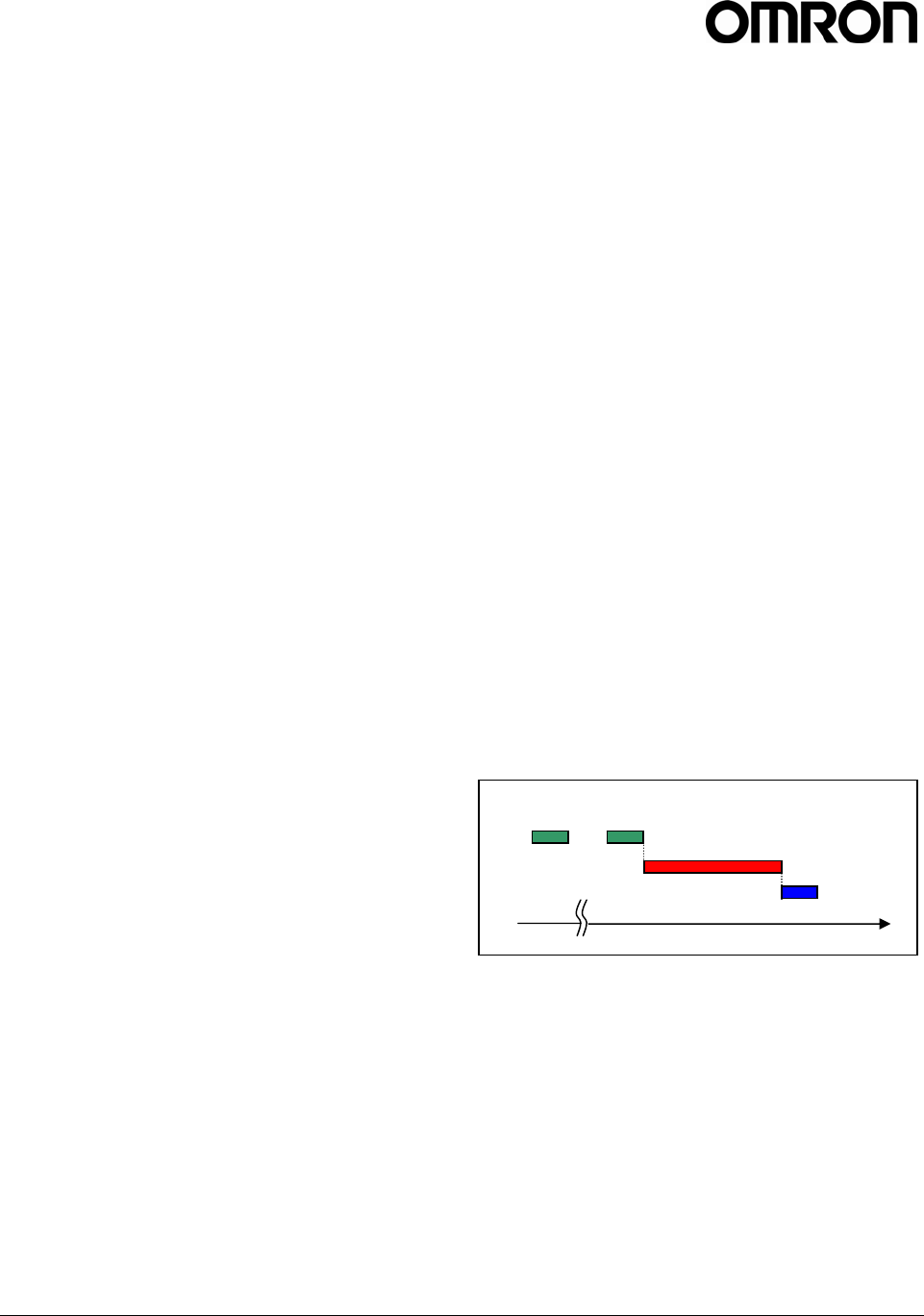
V740 RFID READER/WRITER, ANTENNA 2005-09, REV0.1
OPERATION MANUAL 40 of 56 ©OMRON CORPORATION 2005
4. Reader Control
The client software can register a command with a
cursor name to the reader. This section describes
Cursors (Stored Procedures or Aliases ) and Reader
settings.
i. Cursors
Declare
The client software has the ability to declare cursors
(saved queries), which it can then use to request data
repeatedly using the FETCH or the AUTO_MODE
command. Only one cursor can be executed at one
time. A maximum of 16 cursors can be defined.
To create a cursor:
DECLARE cursorname CURSOR FOR query;
cursorname — an arbitrary string.
query — an RQL query (SELECT/UPDATE
statement), as defined above.
If the query is valid in its syntax, an empty event (only
LF code) is returned. If invalid, an error message is
shown(Ref. Table 9).
Example:
DECLARE cursor1 CURSOR FOR SELECT id,
antenna_id FROM tag_id WHERE
protocol_id='EPC1';
DECLARE cursor2 CURSOR FOR UPDATE
tag_data SET id=0xFEDCBA9876543210
WHERE protocol_id='EPC1' and
antenna_id=1;
Note: Commands for getting information and setting
the separator can not be used as cursors.
Close
Used to close(delete) a cursor and free its
resources(only 16 cursors may be defined
simultaneously). Only one cursor can be closed at one
time. The client software issues the command:
CLOSE cursorname;
If the cursorname is valid, following the command, an
empty event (only LF code) is returned.
Reset
To reset the reader RQL server, for example, if the
RQL state is undefined or questionable, use:
RESET;
Following the command, an empty event (only LF
code) is returned. The command returns the RQL
daemon to its initial state; that is, resets the reader,
deletes cursors and clears memory.
ii. Execution
Commands stored as cursors can be executed in 3
ways as described below.
Fetch
To execute the stored cursor, a FETCH command is
sent by the client software. Only one cursor can be
executed at one time.
FETCH cursorname;
which performs all actions appropriate to the declared
query and sends the result back.
Example:
DECLARE cursor3 CURSOR FOR SELECT id,
antenna_id FROM tag_id WHERE id =
0x11111111111111111111 AND
protocol_id='EPC1';
FETCH cursor3;
could return:
if the tag was read by antenna 2,
0xCE791111111111111111|2<LF><LF>
or if the tag was not found.
<LF>
Auto Mode
The client software may switch the reader into Auto
Mode, causing the reader to repeatedly execute a
cursor indefinitely.
SET auto cursorname = ON, repeat = interval;
For example,
DECLARE cursor4 CURSOR FOR SELECT id,
antenna_id FROM tag_id WHERE
protocol_id='EPC1' SET time_out=250;
SET auto cursor4 = ON, repeat = 500;
Every 500 milliseconds, the cursor executes for 250
milliseconds querying for tags. The remaining 250
time
DECLARE FETCH
RQL execution
Response
Sequence of execution
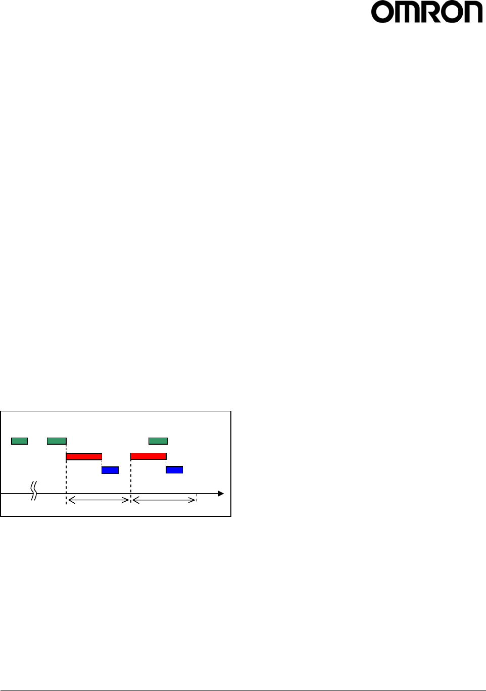
V740 RFID READER/WRITER, ANTENNA 2005-09, REV0.1
OPERATION MANUAL 41 of 56 ©OMRON CORPORATION 2005
milliseconds are spent with cursor idle(RF off). This
syntax can be used for controlling the duty cycle of the
reader. For full reader utilization, ensure that the value
of time_out is less than the value of repeat, if not the
cursor is executed continuously.
Auto Mode can be terminated by sending the
command:
SET auto = OFF;
No other command can be used while Auto Mode is
active.
To schedule intermittent reads with off times of 1
second starting at a specific time use:
Example:
DECLARE cursor5 CURSOR FOR SELECT id
FROM tag_id WHERE protocol_id='EPC1'
SET time_out=500;
SET auto cursor5 = ON, repeat = 1000;
(get resopnses...)
SET auto = OFF;
To turn off Auto Mode, the SET auto = OFF command
is sent by the client software.
1. If the SET command executes while the cursor is
executing, the cursor will finish before Auto Mode
stops.
2. If the SET command executes while the cursor is
idle, then Auto Mode stops immediately.
Scheduled Reads
The reader uses the Network Time Protocol as a
means to establish absolute time on the reader. With
that capability in place the reader is enabled to
execute tag operations that have been scheduled
relative to absolute time. The reader adjusts UTC time
of the NTP server, whatever time zone it works on.
Here is how it works.
First the user declares a cursor , in a way similar to
how to you use cursors in auto mode.
To run the query once at a specific time you use a
command of the form:
SET trigger_time cursorname = 'starttime';
To run the query in auto mode over a given interval:
SET auto_time cursorname = 'starttime',
repeat=interval;
or SET auto_time cursorname =
'starttime/stoptime', repeat=interval;
The first form here starts the auto mode at a given
time, and then just continues until you stop it, the
same way you would stop normal auto mode.
The second form runs during the specified interval.
The start and stop time are specified in ISO8601 time
strings, of the form
YYYY-MM-DDTHH:mm:SS.DDDDZZZZZ
Where YYYY is the year, MM is the month, DD is the
day, HH is the hour, mm is the minute, SS is the
second, and DDDD is the fraction of a second, and
ZZZZZ is the time zone. The seconds and fractions of
a second are both optional (but if you want fractions of
a second, you must specify seconds as well). The
time zone can either be specified as GMT or Zulu time
by using a 'Z' or it can be an offset from GMT using
+HH:MM or -HH:MM. For example, in Eastern time,
that would be -05:00.
Some examples:
C6: DECLARE cursor6 CURSOR FOR SELECT id
FROM tag_id WHERE antenna_id=1 AND
protocol_id='EPC1';
C7: DECLARE cursor7 CURSOR FOR SELECT id
FROM tag_id WHERE antenna_id=2 AND
protocol_id='EPC1';
To run c6 once on February 14th 2004 at 18:54:50
GMT:
SET trigger_time cursor6 = '2004-
02-14T18:54:50Z';
To run c7 for 10 seconds starting in intervals of 1000
ms at 2004-01-20 at 15:37 in Eastern Standard Time:
SET auto_time cursor7 = '2004-01-
20T15:37-05:00/2004-01-20T15:37:10-
05:00', repeat=2000;
Note: If only the start time is specified and the current
time has passed the start time, the cursor is executed
immediately.
If the current time has passed the start time and the
stop time specified in the future, the cursor is
executed immediately and finished at the specified
stop time.
time
DECLARE AUTO ON
RQL execution
Response
repeat repeat
AUTO OFF
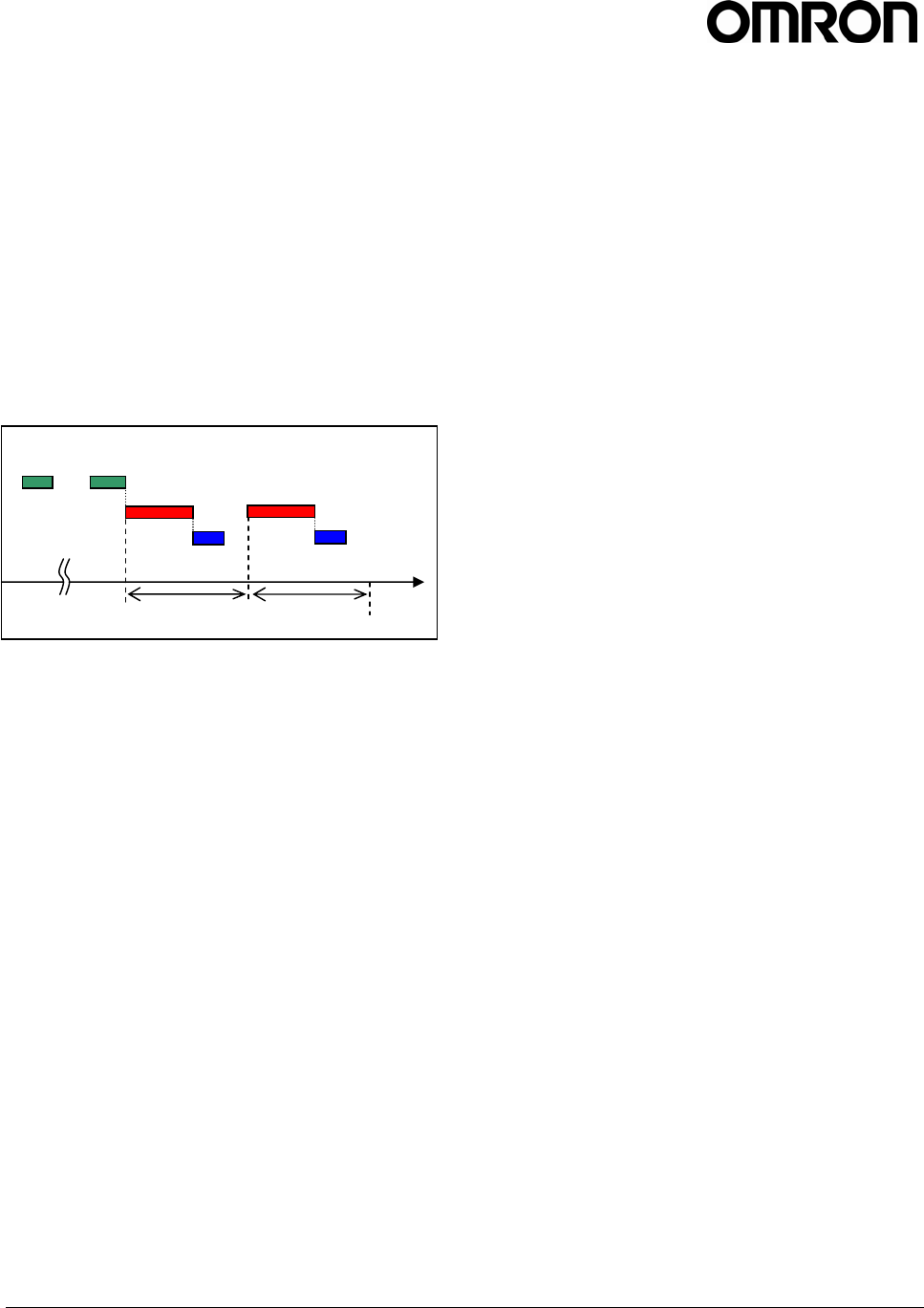
V740 RFID READER/WRITER, ANTENNA 2005-09, REV0.1
OPERATION MANUAL 42 of 56 ©OMRON CORPORATION 2005
Example:
The following example schedules reads to execute 1
time per second with an off time of 750ms, starting at
a specific time:
DECLARE cursor8 CURSOR FOR SELECT id
FROM tag_id WHERE protocol_id='EPC1';
SET auto_time cursor8 = '2004-01-
22T12:43:08-05:00', repeat=1000;
Note: Since time_out is not specified, the default
time_out of 250ms is used.
iii. Setting of ID Read response format
Separator
The client software can change the separator
between the entries of the response for ID
reading.(Ref. 2.2.4.1 ID Read).
SET separator = 'c';
Following the command, an empty event (only LF
code) is returned. The default separator is '|'. The
separator must be one character. Example is as
follows:
SET separator='#';
SELECT id, protocol_id, antenna_id
FROM tag_id WHERE protocol_id='EPC1';
The response would be as follows.
0xCE85123467890ABCDEF#1#1<LF><LF>
Table7 : Table Schema - Reader Control
time
DECLARE SET auto_time
RQL execution
Response
repeat repeat
start time (stop time)

V740 RFID READER/WRITER, ANTENNA 2005-09, REV0.1
OPERATION MANUAL 43 of 56 ©OMRON CORPORATION 2005
Keyword Entry Table Arguments Range Example
Value Comments
DECLARE - n/a cursorname,
query
- cursor1 Defines the cursor name for
the query.
FETCH - n/a cursorname - cursor1 Executes a cursor and
sends the data
CLOSE - n/a cursorname - cursor1 Deletes a defined cursor
RESET - n/a - - - Resets the reader, deletes
cursors, clears memory
tirgger_time n/a cursorname,
time
- - Set a cursor to run at the
specified time once.
auto_time n/a cursorname,
start time,
stop time
- - Set a cursor to keep
running from the start time
to the stop time repeatedly.
auto n/a cursorname,
ON, OFF - cursor1 = ON
Turns auto-mode of cursors
on/off.
repeat n/a Integer - - Sets a cursor to keep
running
SET
separator n/a character except
';' ‘|’ Changes the separator in
the output format of a
query.

V740 RFID READER/WRITER, ANTENNA 2005-09, REV0.1
OPERATION MANUAL 44 of 56 ©OMRON CORPORATION 2005
2.2.4.3 Get Information
The client software can get the information about the
status of the reader. For example, firmware version
and current time of the system. To get firmware
version information, The format is as follows:
SELECT entry FROM table_expression
Table8 : Table Schema - Get Information
Keyword Entry Table Arguments Range Example
Value Comments
version Firmware String - 2.2.22 (2005-
07-
22T16:32:55-
04:00
Shannon)
Requests the
firmware version of
the reader
SELECT
current_time Settings String - 2006-01-
01T00:01:39.8
91808
Requests the
current time of the
reader.
Firmware - - - - Table for the
information about
the reader's
firmware.
FROM
Settings - - - - Table for the
information about
the reader's
settings.

V740 RFID READER/WRITER, ANTENNA 2005-09, REV0.1
OPERATION MANUAL 45 of 56 ©OMRON CORPORATION 2005
2.2.5 Errors
If the reader is unable to execute a command issued
by the client software, the reader issues an error
message, which has the basic form:
Error error_code : string
where error_code is an integer. Error codes and
strings are documented in Table 6.
For example:
DECLARE cursor9 CURSOR FOR SELECT id
FROM tag_id;
FETCH cursor10;
Would result in the error message:
Error 0100: Cursor does not
exist<LF><LF>
Table 9: Error codes and Strings
Error Codes Strings Explanation/Cause
No protocol specified Indicates missing or more than 17
protocol_id are declared (only for UPDATE
command)
Too many protocols specified Indicates too many protocols are declared
(only for UPDATE command)
No antenna specified Indicates missing or more than 17
antenna_id are declared (only for UPDATE
command)
Too many antennas specified Indicates more than 2 antennas
specified(only for UPDATE command)
Unknown table
Cursor already exists Declared cursor name already exists
Unknown setting Indicates no entry item in the table
Cursor does not exist Fetch non-existent cursor
Unknown field Indicates items for GetInfo command (only
for UPDATE command)
Invalid set clause entry
DELETE: Cursor does not exist Indicates a cursor name for CLOSE
command that is not defined by DECLARE
command
Start_time not specified correctly Indicates time format incorrectly for start or
finish time.
time_out value out of range Set sleep time_out value out of range
Unknown protocol Indicates nonexistent protocol
Syntax Error Syntax error or spelling mistake etc
0100 :
ERROR_INVALID
_ARGUMENTS
Invalid argument
Unknown setting
Time is invalid
0101 :
ERROR_INVALID
_DATA Unknown protocol ID

V740 RFID READER/WRITER, ANTENNA 2005-09, REV0.1
OPERATION MANUAL 46 of 56 ©OMRON CORPORATION 2005
Invalid command in current mode Execute a command while another command
is running on auto mode
Error Codes Strings Explanation/Cause
Error performing query Tag is absent.
Argument is illegal.(only for UPDATE
command)
Error setting ping threshold
Error setting saved ping threshold
Error setting saved IP address
Error setting saved gateway
Error setting saved netmask
Error setting firmware version
Error setting safemode version
Error setting OS version
Error setting supported protocols
0102 :
ERROR_REMOT
E
Error getting operation state
0106 :
ERROR_INVALID
_ANTENNA
Antenna does not exist in current
hardware configuration Antenna does not exist in current hardware
configuration.
0107 :
ERROR_UNCON
NECTED_ANTEN
NA
Antenna port exists. But no antenna
connected Antenna port exists. But no antenna
connected.
Tag data access failed Table name on update command is invalid
Error getting entry
Error getting ip address entry
Error getting netmask entry
0199:
ERROR_UNKNO
WN
Error getting gateway entry

V740 RFID READER/WRITER, ANTENNA 2005-09, REV0.1
OPERATION MANUAL 47 of 56 ©OMRON CORPORATION 2005
2.2.6 Protocol Specific Functionality and Parameter Settings
While the standard ID_read and anti-collision searches are supported by practically all offered protocols,
therefore no protocol-specific information is required to issue a RQL search. More specific commands, such as
data_read and data_write require protocol specific information when formatting the query and interpreting the
results. The tables below provide that information.
2.2.6.1 915 MHz EPC Class 1/1B
Parameters /
Constraints Return Value
(String) Example
Read ()
Class1: 80 bits (64
bits ID and 16 bits
CRC, hex format)
Class1B: 112 bits
(96 bits ID and 16
bits CRC)
SELECT id FROM tag_id WHERE
protocol_id='EPC1';
Write
id: 64 bits
or 96 bits
(hex)
new_id or error_code
with string
UPDATE tag_id SET
id=0x1234567890ABCDEF WHERE
protocol_id='EPC1' AND
antenna_id=1;
ID
Lock
id: 64 bits
or 96 bits
(hex)
Locked Flag:
1(Fixed)
id or error_code
with string
UPDATE tag_id SET locked=1,
id=0x1234567890ABCDEF WHERE
protocol_id='EPC1' AND
antenna_id=1;
Kill
id: 64 bits
or 96 bits
(hex)
password:
8bits(hex)
Killed Flag:
1(Fixed)
all zero id or
error_code with
string
UPDATE tag_id SET killed=1,
password=0x88,
id=0x1234567890ABCDEF WHERE
protocol_id='EPC1' AND
antenna_id=1;
Password
id: 64 bits
or 96 bits
(hex)
password:
8bits(hex)
password or
error_code with
string
UPDATE tag
_
id SET
password=0x88,
id=0x1234567890ABCDEF WHERE
protocol_id='EPC1' AND
antenna_id=1;
Note: The state of the tag becomes 'Quiet' after reading by RQL. If you wish to communicate with the tag
using a 2nd reader, a ‘Talk’ command must be sent to change the tag to active mode.(for more detailed
information about the status of the tag see 'Communication Interface Specification' for EPC1)
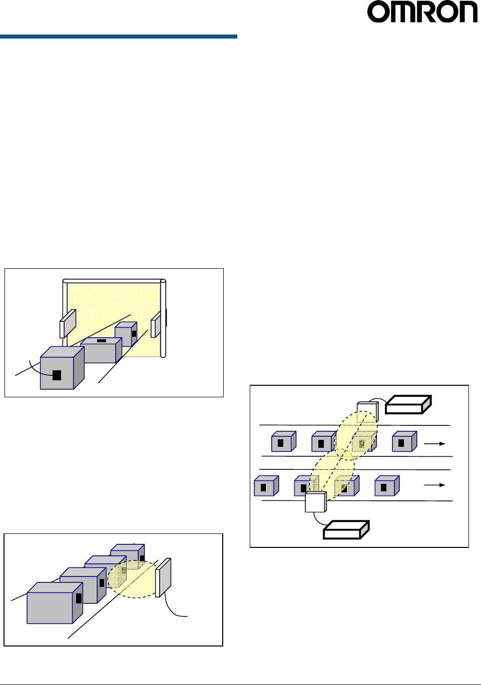
V740 RFID READER/WRITER, ANTENNA 2005-09, REV.01
OPERATION MANUAL 48 of 56 OMRON CORPORATION 2005
2.3 Examples
Examples given in this chapter are provided as a
guide for the user in determining suitability and does
not constitute a warranty. Users must verify operation
in their specific environment and application.
2.3.1 Example 1
To read tags attached to cases passed through a gate
on a conveyer, the client software finds tags using 2
antennas. For the example pictured below, the
command is as follows:
SELECT id, antenna_id FROM tag_id
WHERE (antenna_id=1 OR antenna_id=2)
AND protocol_id='EPC1' SET
time_out=500;
Then the reader continues to read tags through the
gate.
2.3.2 Example 2
To read tags and send a response repeatedly every 1
second using one antenna. For the example pictured
below, the command is as follows:
DECLARE query1 CURSOR FOR SELECT id
FROM tag_id WHERE antenna_id=1 AND
protocol_id='EPC1' SET time_out=500;
SET AUTO query1=ON, repeat=1000;
2.3.3 Example 3
To synchronize two readers see the following
instructions.
On Reader 1:
DECLARE cursor_one CURSOR FOR SELECT
id FROM tag_id WHERE
protocol_id='EPC1' SET time_out=300;
SET auto_time cursor_one = '2005-02-
01T13:00:00Z', repeat=1000;
The first reader will start reading for no less than 300
ms at just 13 o’clock, and it will repeat the command
1000ms.
On Reader 2:
DECLARE cursor_two CURSOR FOR SELECT
id FROM tag_id WHERE
protocol_id='EPC1' SET time_out=300;
SET auto_time cursor_two = '2005-02-
01T13:00:00.5Z', repeat = 1000;
The second reader will start reading for no less than
300ms starting at time 0.5 second after 13 o’clock,
and it will repeat the command every 1000ms.
The effect will be that each reader will have a almost
50% duty cycle with each one only active when the
other one is off.
cases
conve
y
o
r
antenna 2
antenna 1
ta
g
antenna 1
Reader 1
Reader 2
Line 1
Line 2
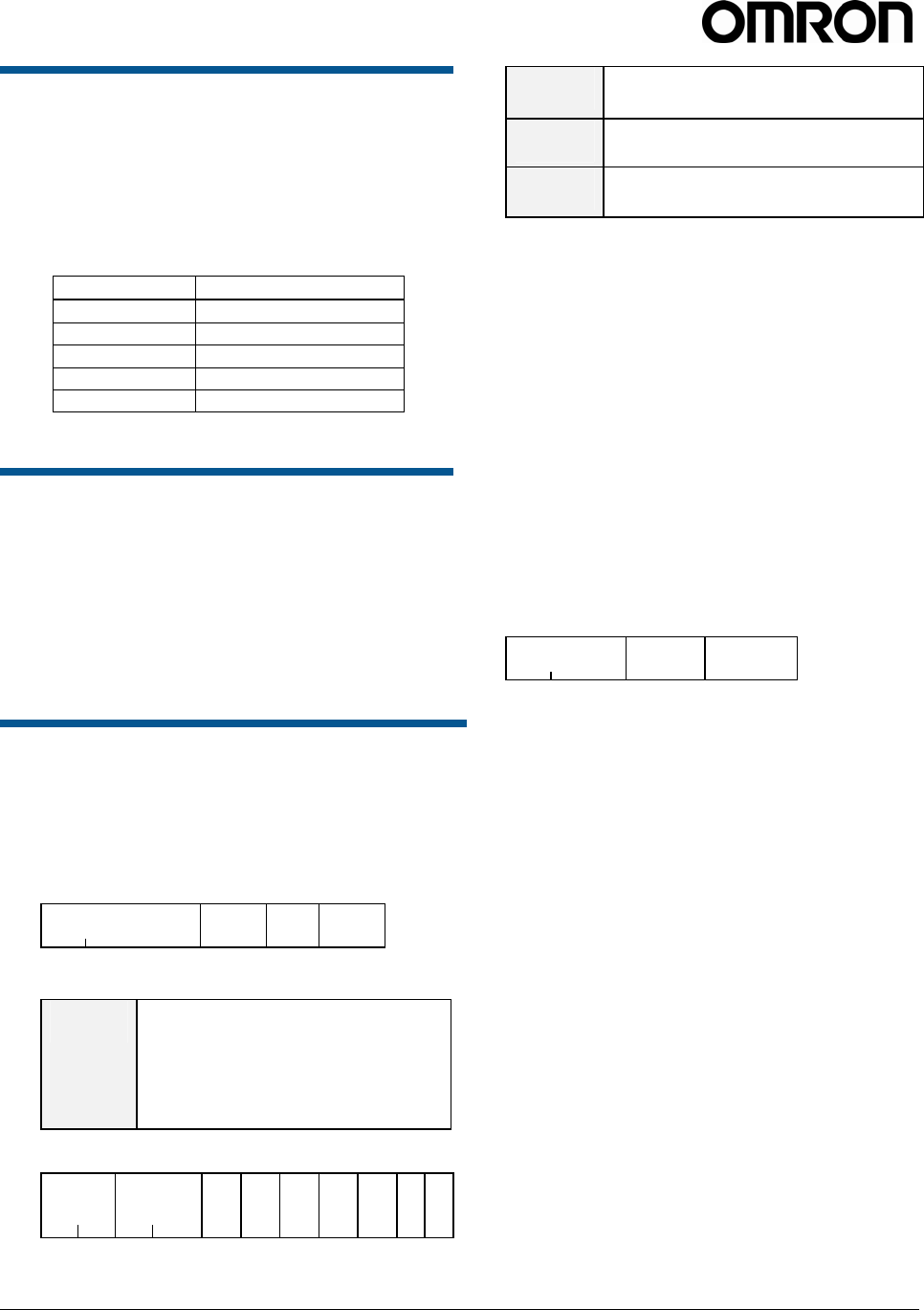
V740 RFID READER/WRITER, ANTENNA 2005-09, REV.01
OPERATION MANUAL 49 of 56 OMRON CORPORATION 2005
3. I/O
This chapter describes how to use this function a
function for external input/output control.
The V740 Reader has an external input/output
function on the RS232C connector; two for input
and three for output. Following table is a terminal
assignment.
RS232C Connector
Input 1 pin 4
Input 2 pin 7
Output 1 pin 6
Output 2 pin 1
Output 3 pin 9
3.1 Using the input/output
function
1. Start the socket communication program created
by users. In the open window connect to the IP
address of V740 on port 8091.
2. Send the I/O control command (“CC”) to the
reader.
3.2 Detailed Command structure
1. I/O Control Command (CC)
CC changes statuses of external input/output
connectors (OUT1, OUT2, OUT3, IN1 and IN2)
and read their statuses.
< Command format>
Command code
“CC” OUT1 OUT2 OUT3
2 1 1 1
OUT1-
OUT3 Writing “1” or “0” following CC
specifies the status of the output.
1:ON/0:OFF
Writing “*” instead of “1” or “0”
starts to read the statuses of the
connectors.
< Response format >
Coomand
“CC” Response
Code
“00”
OUT
1OUT
2 OUT
3 IN
1 IN
2LF LF
2 2 1 1 1 1 1 1 1
Response
Code 00 : Normal
14 : Format Error
OUT1 -
OUT3 Displays the status of output.
1 : ON / 0 : OFF
IN1,
IN2 Displays the status of input.
1 : ON / 0 : OFF
Example (1) To output +5V from OUT1, -5V from
OUT2 and +5V from OUT3, enter the below command
and the following response will be received.
Command: CC101
Response: CC000101<LF><LF>
Example (2) To read the statuses of each connector;
OUT 1-3 and IN 1 and 2, enter the below command
and the following response will be received.
Command: CC***
Response: CC0001010<LF><LF>
2. Invalid Command Response
Invalid Command Response is sent whenever the
reader receives any invalid or undefined
commands.
< Response format>
Command code
“IC” LF LF
2 1 1
For example, if the invalid command =”AA” is sent,
in response to the command, the following data will
be received.
Command: AA000
Response: IC<LF><LF>
.
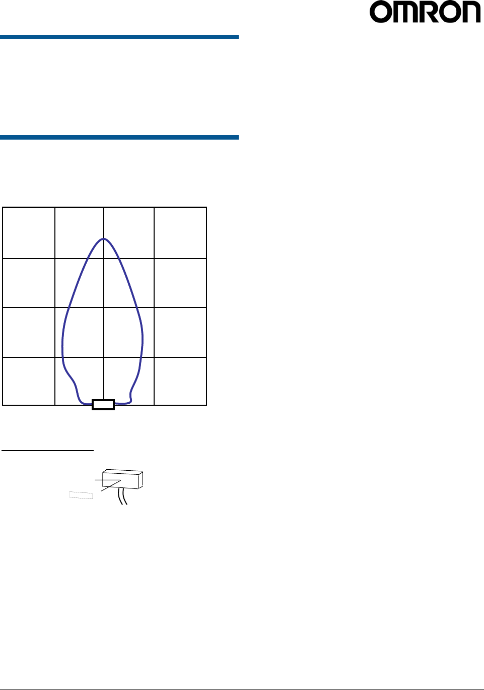
V740 RFID READER/WRITER, ANTENNA 2005-09, REV.01
OPERATION MANUAL 50 of 56 OMRON CORPORATION 2005
4. Characteristics(Reference)
Characteristics data given in this chapter is provided
as a guide for the user in determining suitability and
does not constitute a warranty. Actual performance
may vary based on actual user conditions.
4.1 Communications Range
Circular Antenna(V740-HS02CA,04C) /
Class1b Tag
<Measurement Set-up>
*. There are no RF reflection objects around the Antenna and Tag
in the measurement environment.
*. There are some areas where communication is possible outside
the communications range shown in the graph by the effect of
reflection off of the ground.
For example, an electric wave darkroom.
*. 6dB attenuator is attached at the time of measurement with a
Liner polarization antenna.
3dB attenuator is attached at the time of measurement with a
Circular polarization antenna.
X
Y
Antenna
Tag
1m 2m1m 2m
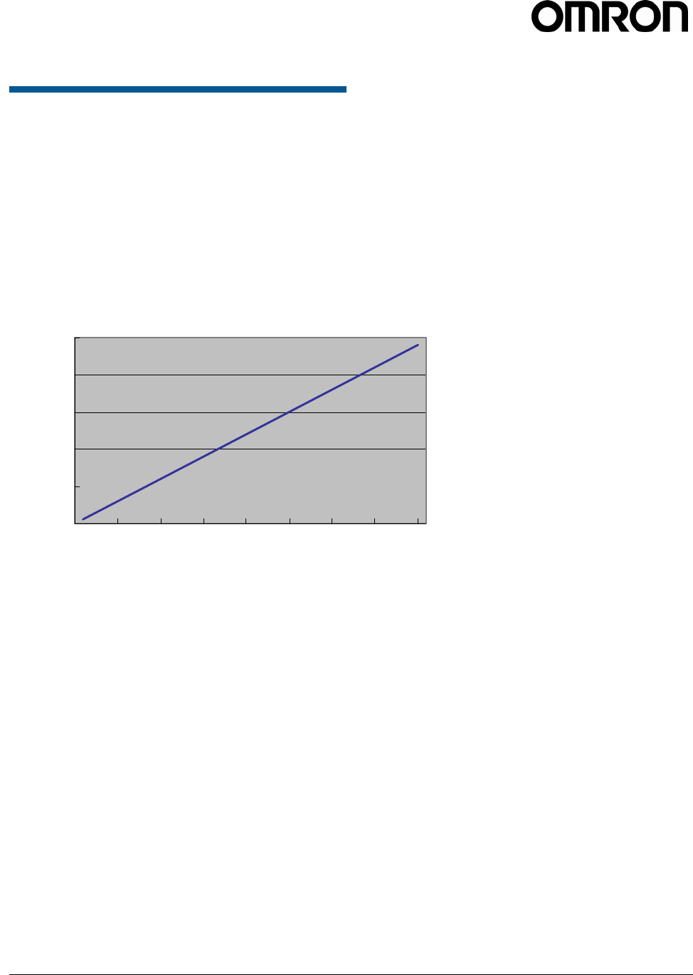
V740 RFID READER/WRITER, ANTENNA 2005-09, REV.01
OPERATION MANUAL 51 of 56 OMRON CORPORATION 2005
4.2 Communications Time
Communications time varies for several reasons
such as the actual noise environment and the
distance between tags and antennas. The chart
below shows the communication time vs. the
number of tags in the antenna read range. One may
use the communication time value as a reference
when setting time out values in the RQL command.
Class1/1b Tags
0
200
400
600
800
1000
0 5 10 15 20 25 30 35 40
Number of Tags
Actual communication time (ms)
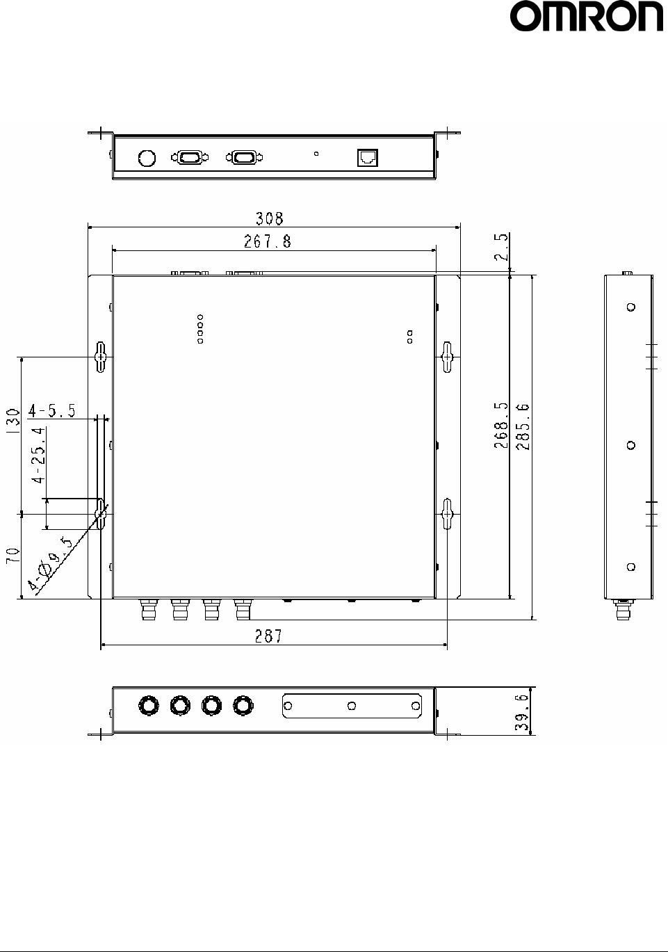
V740 RFID READER/WRITER, ANTENNA 2005-09, REV.01
OPERATION MANUAL 52 of 56 OMRON CORPORATION 2005
APPENDIX : OUTLINE DRAWINGS
Reader : ( V740-BA50C22A-US)
Material : Aluminium
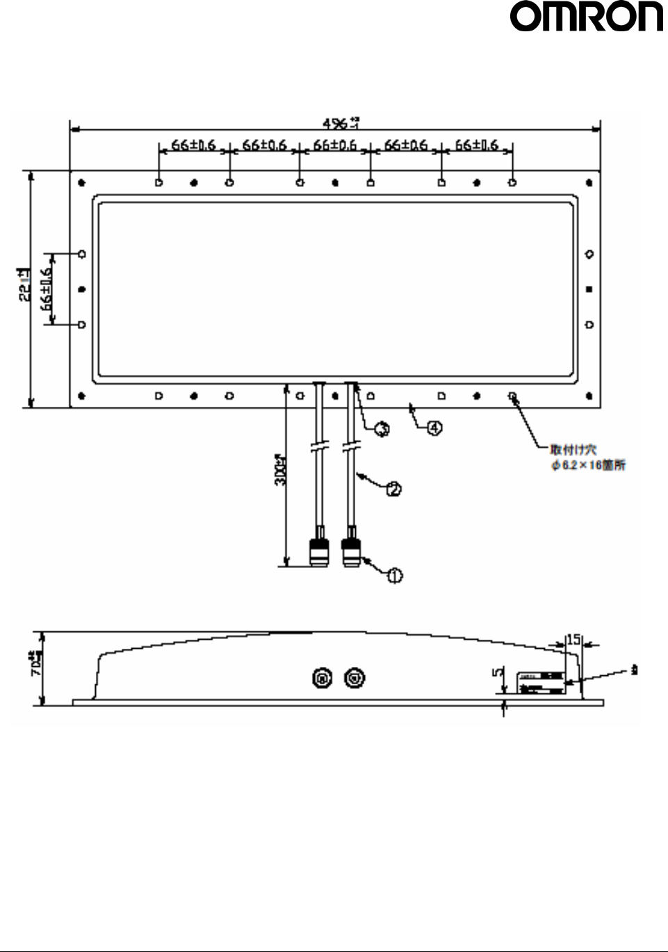
V740 RFID READER/WRITER, ANTENNA 2005-09, REV.01
OPERATION MANUAL 53 of 56 OMRON CORPORATION 2005
Antenna : ( V740-HS02CA,V740-HS02C)
Material : Aluminium
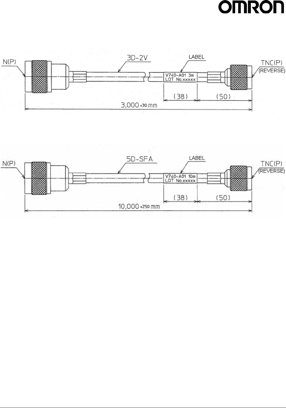
V740 RFID READER/WRITER, ANTENNA 2005-09, REV.01
OPERATION MANUAL 54 of 56 OMRON CORPORATION 2005
Antenna Cable:
Short cable (V740-A01-3.0M)
Long cable ( V740-A01-10M)
V740 RFID READER/WRITER, ANTENNA 2005-09, REV.01
OPERATION MANUAL 55 of 56 OMRON CORPORATION 2005
Revision History
Catalog No. RFM - 002 - 01
Revision Code Date Reason for revision/revised page
01 2005/11 First edition
Revision Code

V740 RFID READER/WRITER, ANTENNA 2005-09, REV.01
OPERATION MANUAL 56 of 56 OMRON CORPORATION 2005
OMRON CORPORATION
RFID BUSINESS DEVELOPMENT DEPARTMENT
14th Fl., Gate City Osaki West Tower
1-11-1 Osaki, Shinagawa-ku,
Tokyo 141-0032 Japan
Tel: (81)3-5435-2016/Fax: (81)3-5435-2017
Regional Headquarters
OMRON ELECTRONICS LLC
1 East Commerce Drive, Schaumburg, IL 60173
U.S.A.
Tel: (1)847-843-7900/Fax: (1)847-843-8568
Up-to-date information on RFID Systems can be accessed at OMRON's web site at
http://www.omron.com/card/rfid/
Up-to-date information on RFID Systems can be accessed at OMRON's web site at
http://www.omron.com/card/rfid/
Cat. No. RFM - 002 - 01 Note: Specifications subject to change without notice. Printed in Japan