Omron RFID Business Development Department V740-BA50CX4 Radio Identification System User Manual users manual
Omron Corporation, RFID Business Development Department Radio Identification System users manual
UserManual.wiki
>
Omron RFID Business Development Department
>
V740 BA50CX4 User Manual
users manual
Navigation menu
Upload a User Manual
Namespaces
Wiki Guide
HTML
PDF
Info
Views
User Manual
Discussion / Help
Navigation
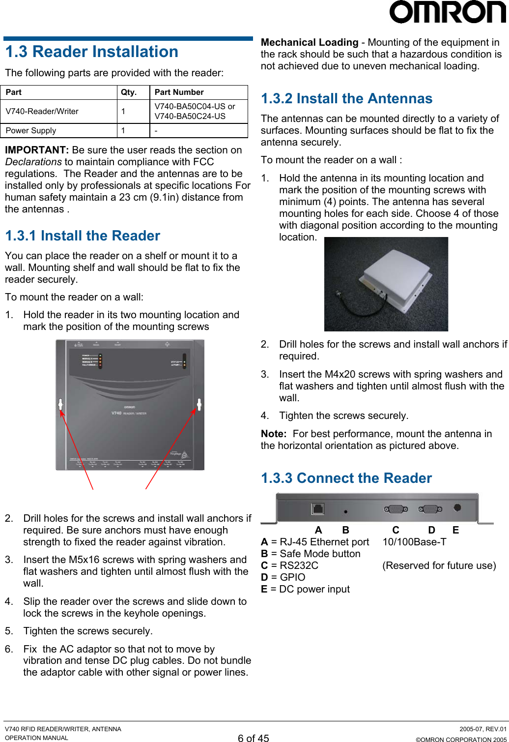
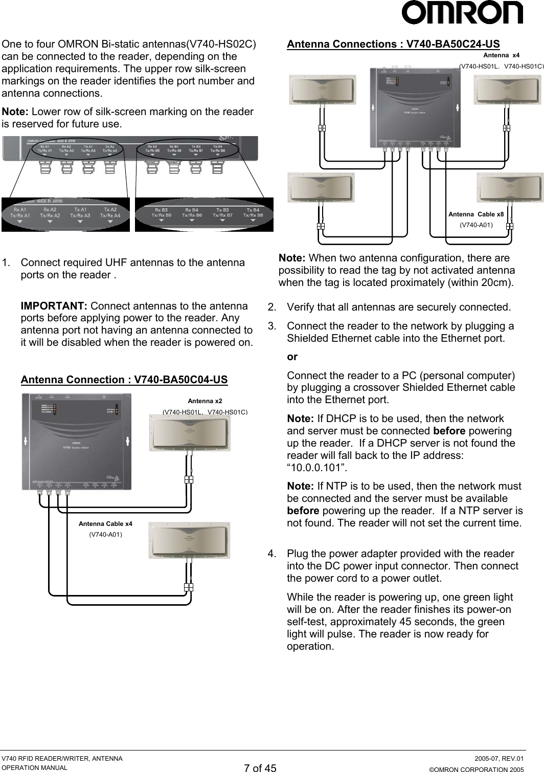
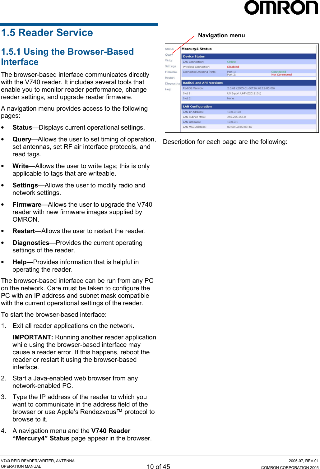
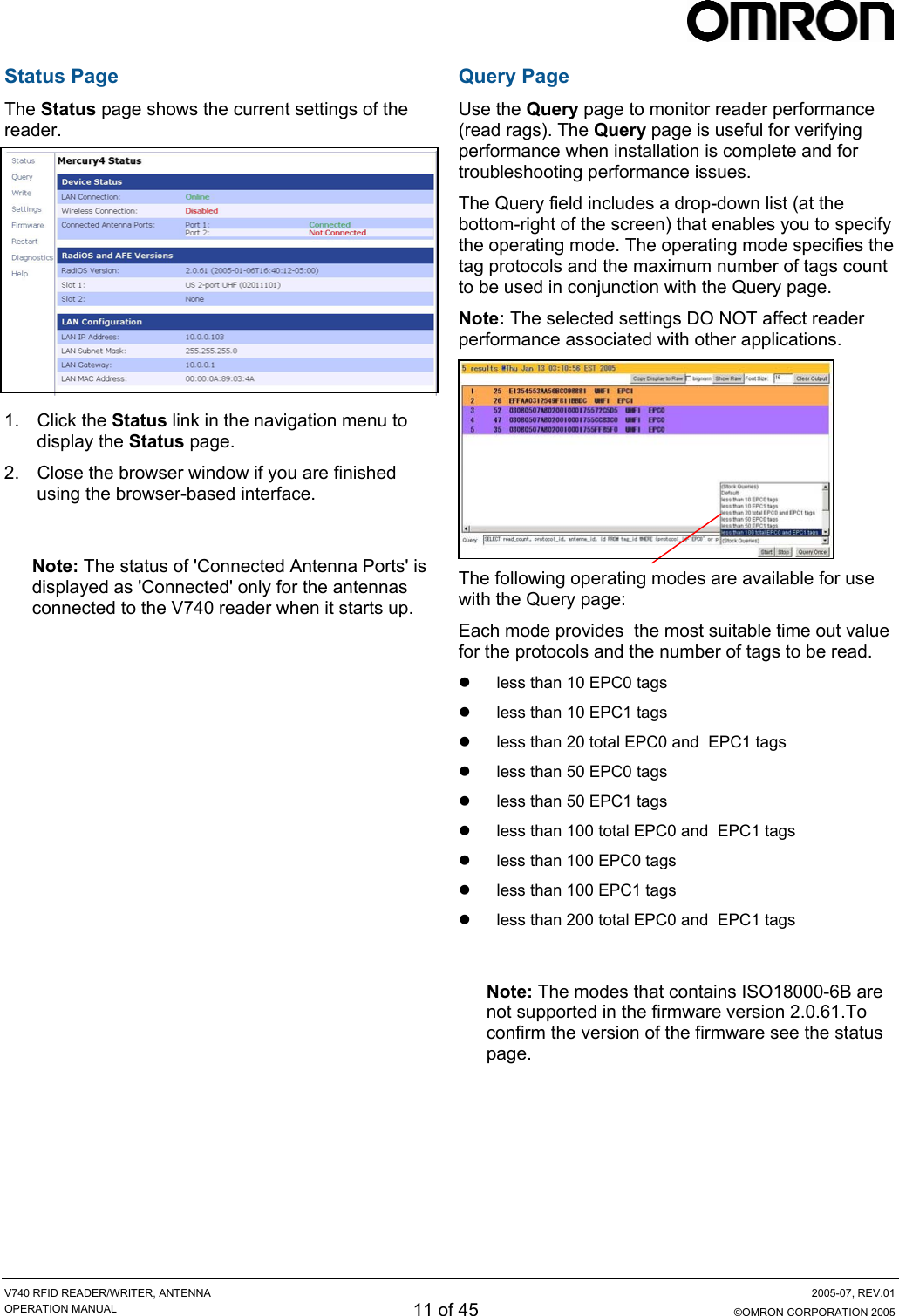
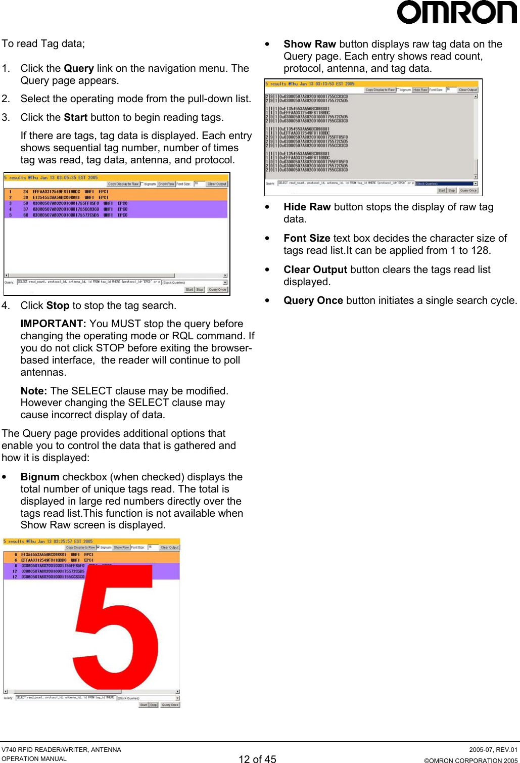
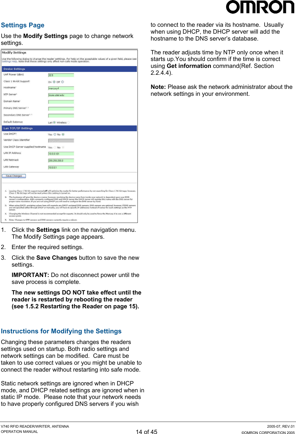
![V740 RFID READER/WRITER, ANTENNA 2005-07, REV.01 OPERATION MANUAL 9 of 45 ©OMRON CORPORATION 2005 1.4 Reader Configuration In some cases, the application software may provide support for reader configuration. If so, follow the instructions provided with the application. The following procedure describes how to configure the reader directly from a network PC using the browser-based interface. The reader is shipped to use DHCP by default but will fall back to the following static network configuration if it does not get a DHCP lease: IP Address: 10.0.0.101 Subnet Mask: 255.255.255.0 Gateway: 10.0.0.1 You must know the IP address and subnet mask settings for the network environment in which the reader will be running or you may use Apple’s Rendezvous™ protocol (download Rendezvous™ from Apple’s website) to browse to it. Also if DHCP and the DNS function are available on the server such as Microsoft® Windows® 2000 server operating system, it can tell you an IP address and a hostname. Note: Please contact Apple about operating the Rendezvous™ technology. 1. Exit any reader applications that are running on the network. IMPORTANT: Running another reader application while using the browser-based interface may cause a reader error. If this happens, reboot the reader or restart the system using the browser-based interface. 2. Verify that the reader is operational. All LED’s should be out except for the green power LED which should be pulsing. 3. Start a Java-enabled web browser from any network-enabled PC. This PC must be configured with an IP address and subnet mask compatible with the reader’s settings. For example: IP address 10.0.0.10 Subnet mask 255.255.255.0 4. Browse to… http://mercury4 (dhcp name) or http://10.0.0.101 The V740 Reader browser-based interface to the reader is displayed. 5. Click the Settings link in the navigation menu. The Modify Settings page appears. 6. If you wish to use DHCP, modify the “Use DHCP?” setting by selecting the “Yes” radio button; otherwise, enter the required network settings in the IP Address, Subnet Mask, and Gateway fields. The fields will turn red if the gateway is not on the same subnet as the IP address. Then, click the [Save Changes] button. IMPORTANT: Do not disconnect power until the save process is completed. 7. Set the reader RF power per instructions on page 5 to correspond to antenna and cable types. 8. Verify that the settings shown are correct. Then, restart the reader by disconnecting the power cable and then reconnecting it. It may take about 60 seconds for the reader to restart. If the reader IP address was changed, you must type the new address into the PC browser address field to communicate with the reader. IMPORTANT: Do not disconnect and connect power cable at the DC cord. Always disconnect and connect power cable at the AC cord. 9. Once the system restarts, click Settings. You are taken to the Modify Settings page. Your changes will be saved and then applied. After the reader reconfigures its network interfaces, it will automatically redirect you to its status page. There is no need to restart the reader. IMPORTANT: Do not disconnect power while the reader is saving its new configuration. The reader is now ready to receive commands from the network. 10. Use the Query page of the browser-based interface to verify the reader and antenna operation by reading tags. 11. Close the browser window. Start an application to control the reader on the network.](https://usermanual.wiki/Omron-RFID-Business-Development-Department/V740-BA50CX4/User-Guide-577901-Page-9.png)
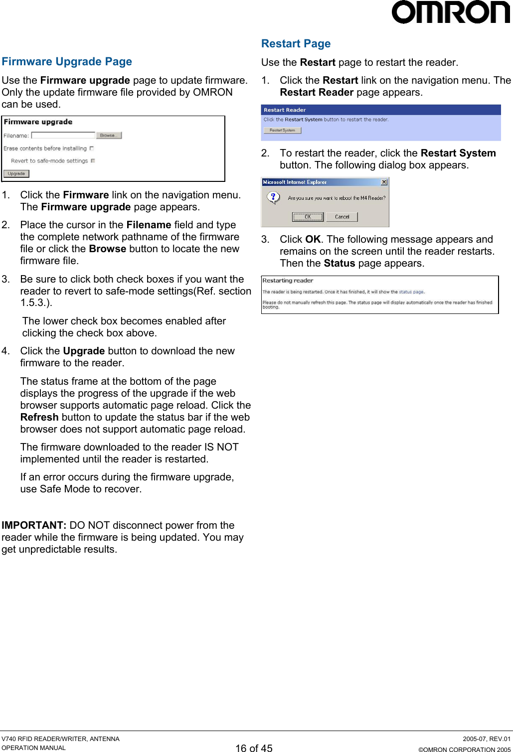
![V740 RFID READER/WRITER, ANTENNA 2005-07, REV.01 OPERATION MANUAL 19 of 45 ©OMRON CORPORATION 2005 5. Click the Settings link on the navigation menu and verify the new settings. Be sure to click [SAVE] to store all settings changes. 6. Restart the reader with the new settings. Once the restart is complete, the reader is no longer in Safe Mode. A navigation menu provides access to the following pages: • • • • • Status—Displays current settings in safe mode. Settings—Displays current settings in normal mode. And allows the user to modify network settings. Firmware—This page can be used to upgrade the tag reader with new firmware images supplied by OMRON. Restart—Allows the user to restart the reader. Diagnostics—This page provides the current operating settings in safe mode. Help—This page provides information that is helpful in operating the tag reader. Note: Enabling Safe-Mode resets all settings to factory default. Modify settings in the normal mode as required for the application.](https://usermanual.wiki/Omron-RFID-Business-Development-Department/V740-BA50CX4/User-Guide-577901-Page-19.png)
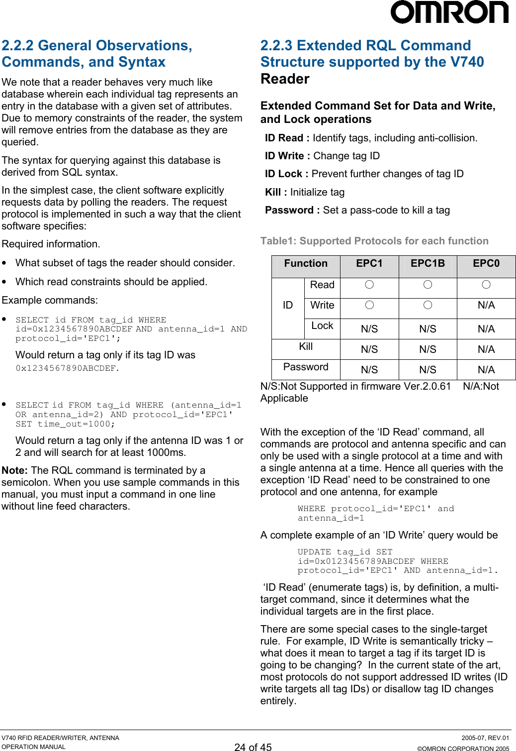
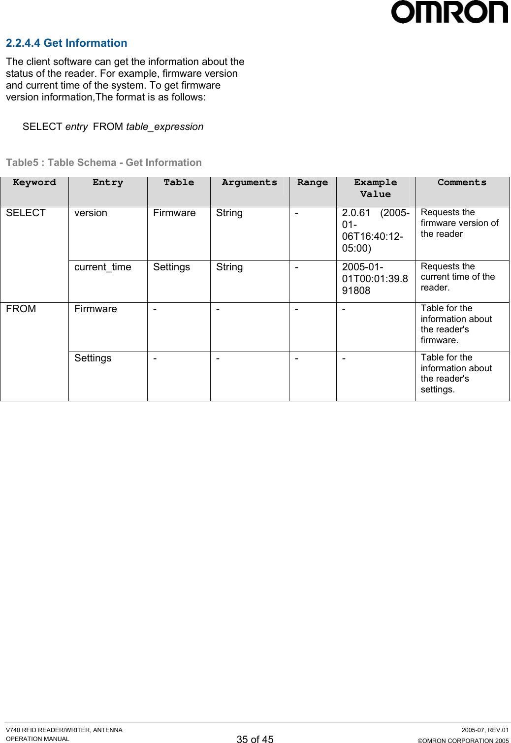
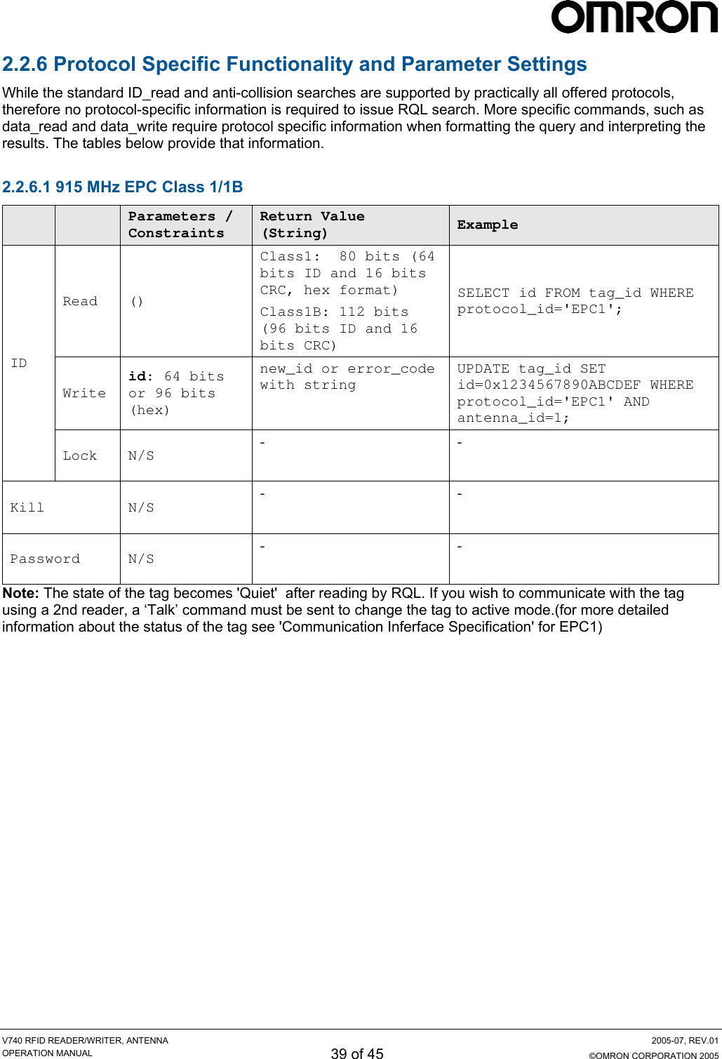
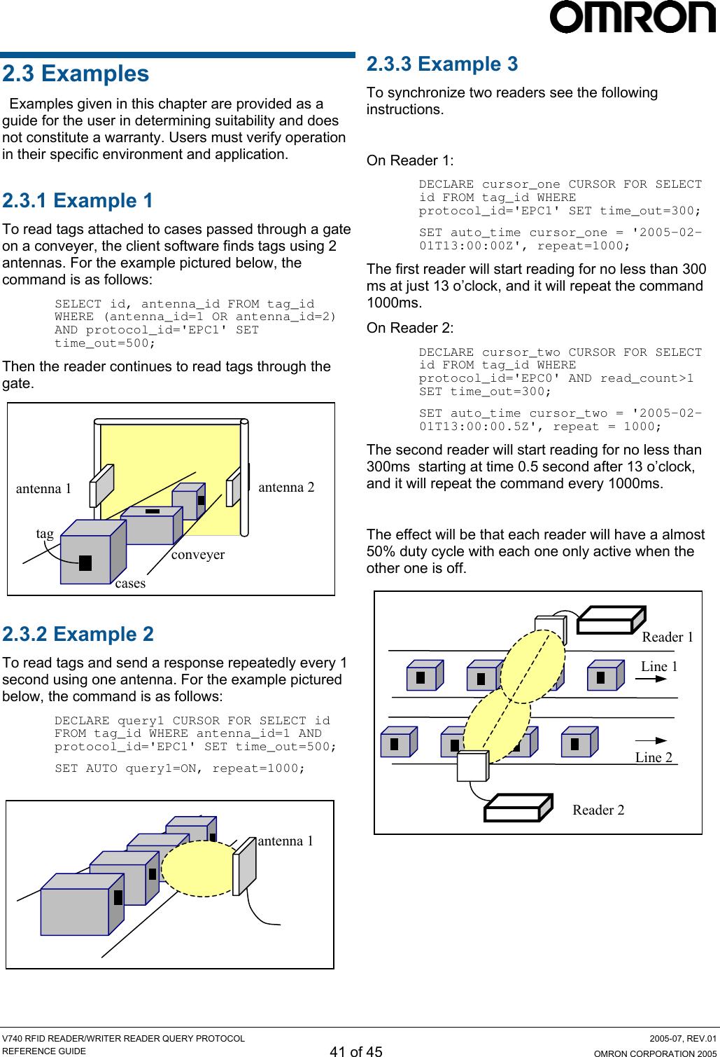
![V740 RFID READER/WRITER, ANTENNA 2005-07, REV.01 OPERATION MANUAL 25 of 45 ©OMRON CORPORATION 2005 2.2.4 Detailed Command Structure 2.2.4.1 ID Read The client software would use the SELECT command to read IDs of tags. The SELECT command is for querying the tag population of the reader as well as static variables such as firmware version. The structure of a SELECT command is as follows: SELECT entry_list FROM table_expression where_specification [set_specification]; Ref. Table 2 for entry_list details. A SELECT clause is entered as: SELECT entry1, entry2, entry3, ... one or more entries can be specified, for multiple entries, a comma delimiter is required. A table_expression is specified by only one table name. FROM table In the function ID Read, you always use 'tag_id' as a table name. And so the table_expression is as follows: From tag_id A where_specification is entered as: WHERE boolean_expr boolean_expr can consist of any expression which evaluates to a boolean value. In many cases, this expression will be: entry binary_operator value where binary_operator can be one of =, <, <=, >, >= , <>, AND, or OR. Parentheses may also be used to create associations of subexpressions. In the presence of a 'where_specification', SELECT will not return any rows for which the WHERE condition does not evaluate to TRUE. Note: You must specify one or more protocols in 'where_specification'. A set_specification is entered as: SET expression expression consists of entry and the value. In response, all IDs delimitted by LF code are sent. The format is as follows: [id1] <LF> [id2] <LF>.....[idn] <LF><LF> The response includes the check code and ID. The first 4 digits are the check code, and the ID follows for the EPC1/1B protocols. For EPC0, the 24 digits ID is first, followed by the 4 digit check code. Below are some examples for reading tag ID: • To query a tag on a specific antenna and protocol, you can specify a specific antenna and protocol in the 'where_specification': SELECT id FROM tag_id WHERE antenna_id=1 AND protocol_id='EPC1'; SELECT id FROM tag_id WHERE antenna_id=2 AND protocol_id='EPC0'; The first specifies 1 as an antenna id, and EPC1 as a protocol id. The second specifies 2 as an antenna id, and EPC0 as a protocol id. The reader searches tags that corresponds to the condition, and returns the tag ID if the tag is present followed by LF code, an empty event (only LF code) results if tags matching the 'where_specification' are not present. • To query a tag on multiple antennas and protocols, you can specify multiple antennas and protocols by 'OR' operator in the 'where_specification': SELECT id FROM tag_id WHERE (antenna_id=1 OR antenna_id=2) AND protocol_id='EPC1'; SELECT id FROM tag_id WHERE antenna_id=2 AND (protocol_id='EPC1' OR protocol_id='EPC0'); The first specifies 2 antennas, and the second specifies 2 protocols. • To query a specific tag, given its EPC code, one can specify a specific tag with an ID as a hexadecimal number: SELECT id FROM tag_id WHERE id=0x1234567890ABCDEF AND antenna_id=1 AND protocol_id='EPC1'; When Indicating id in the 'where_specification', the reader searches the ID from the higher order. If the value is shorter than 16 digit for EPC1(24 digit when using EPC1B), it examines only upper bits. SELECT id FROM tag_id WHERE antenna_id=1 AND protocol_id='EPC1' AND id=0x1234;](https://usermanual.wiki/Omron-RFID-Business-Development-Department/V740-BA50CX4/User-Guide-577901-Page-25.png)
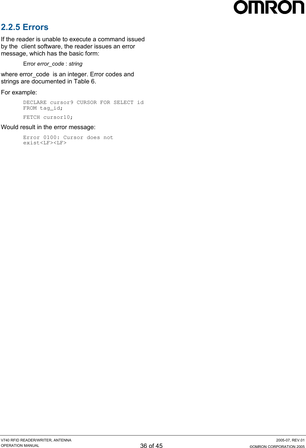
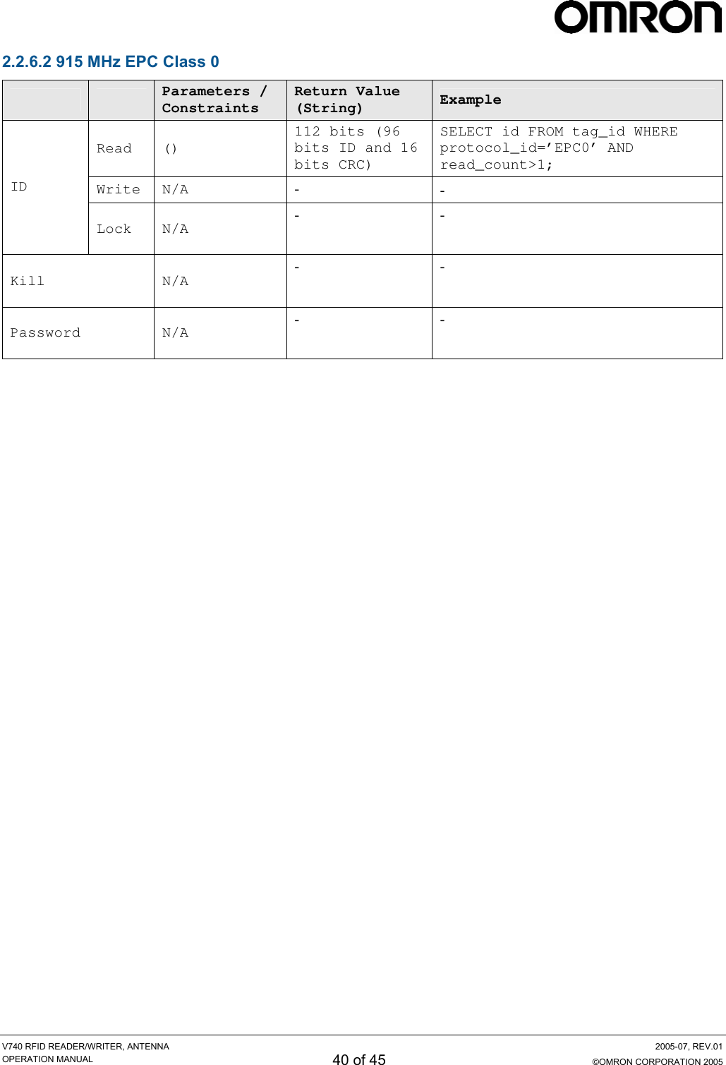
![V740 RFID READER/WRITER, ANTENNA 2005-07, REV.01 OPERATION MANUAL 26 of 45 ©OMRON CORPORATION 2005 • To query EPC0 tags: • To query a specific sub class of tags, given a range of tag ID values: When the client software reads tags of the 'EPC0' protocol, it should indicate 'read_count>1' in the 'where_specification'. SELECT id FROM tag_id WHERE protocol_id='EPC1' AND tag_id>=min_tag_id AND tag_id<=max_tag_id; For example, the command is as follows: The reader returns the tag ID values for all the present tags between min_tag_id and max_tag_id, which are hexadecimal values. SELECT id FROM tag_id WHERE antenna_id=1 AND protocol_id='EPC0' AND read_count>1; To read EPC1 and EPC0 tags at the same time: • To query tags by specific or all antennas: SELECT id FROM tag_id WHERE protocol_id='EPC1' OR (protocol_id='EPC0' AND read_count>1); SELECT id FROM tag_id WHERE antenna_id=1 AND protocol_id='EPC1'; SELECT id FROM tag_id WHERE protocol_id='EPC1'; Note: If you don't specify the 'read_count>1', the reader returns ghost data occasionally. 'Ghost data' means the data which is returned even if tags do not exist in the antenna field. At the first, the reader searches tags only by antenna 1. Second the reader searches tags by all antennas available. Omitting the antenna indication in the 'where_specification' means to search all antennas available. • To query during a specific time: SELECT id FROM tag_id WHERE antenna_id=1 AND protocol_id='EPC1' SET time_out=500; Note: When specifying multiple antennas even if an antenna that does not exist is specified, the reader obtains the tag ID only using antenna 1 and doesn't return any an error message. The command imposes a time out constraint of 500ms; i.e., the reader stops reading and returns all collected data after 500ms. The order in which specifying arguments are used is irrelevant. The default timeout is 250ms if none is specified. SELECT id FROM tag_id WHERE (antenna_id=1 OR antenna_id=5) AND protocol_id='EPC1'; It is important to always use a timeout in specifying a query to achieve optimal performance for a given application. Detailed information will be discussed in the next section • The client software can specify multiple entries in the select_list field of the SELECT command: SELECT id, antenna_id FROM tag_id WHERE antenna_id=1 AND protocol_id='EPC1'; Timeout SELECT protocol_id, timestamp, id, antenna_id FROM tag_id WHERE antenna_id=1 AND protocol_id='EPC1'; The client software can impose a time limit on a read operation, requesting the reader to search only for a limited time (specified in milliseconds). The reader may fail to detect some tags if insufficient time is allocated to the search operation. The time_out is the parameter used for specifying the time allocated for the read operation. The first example returns the tag IDs and antenna_ids, and the second returns protocol_ids and the time that the tag was read (seconds from the unix epoch, Jan 1, 1970) with the tag IDs and antennas_ids. Note: To read timestamp, the NTP sever must be set up in advance. The reader returns protocol_id as an integer value. The value '1' represents 'EPC1',and the value '9' represents 'EPC0'. For example, the query with protocol_id and the response is as follows: In general, a large time_out should be used for dock stations (>2000ms), and short time_outs should be used for conveyor belts (<100ms). DockStation Conveyor Application short time outlong[Query] SELECT protocol_id, id FROM tag_id WHERE antenna_id=1 AND protocol_id='EPC1'; [Res] 1|0xCE791111111111111111<LF><LF> SELECT id FROM tag_id SET time_out=1000;](https://usermanual.wiki/Omron-RFID-Business-Development-Department/V740-BA50CX4/User-Guide-577901-Page-26.png)
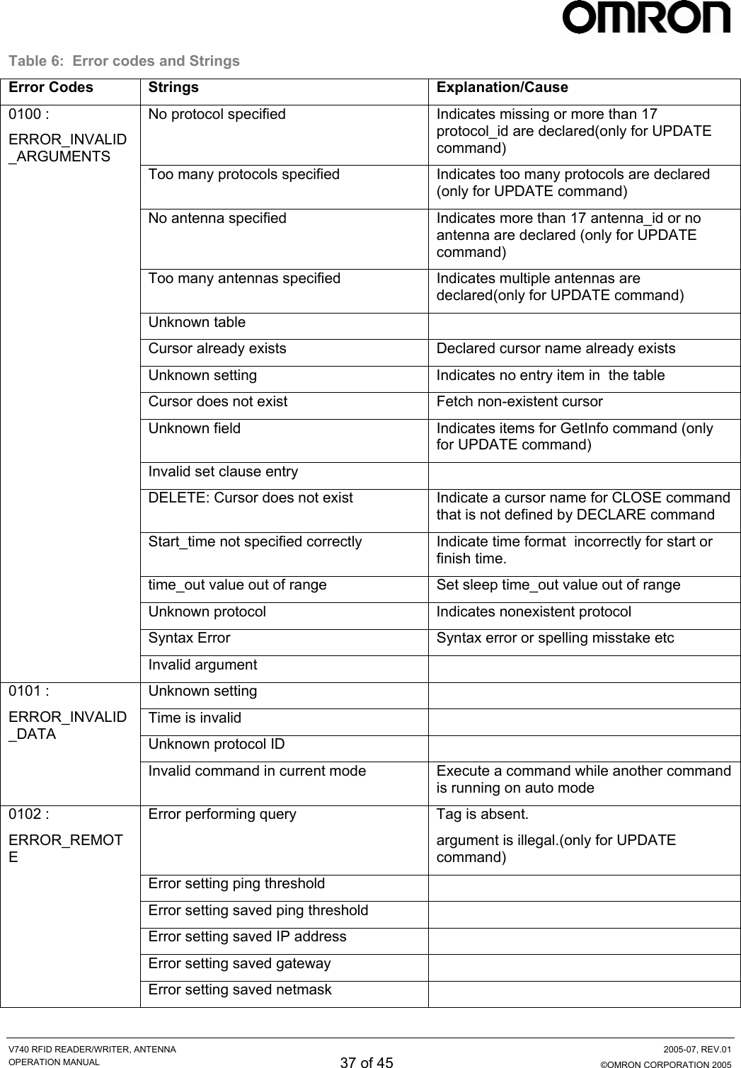
![V740 RFID READER/WRITER, ANTENNA 2005-07, REV.01 OPERATION MANUAL 28 of 45 ©OMRON CORPORATION 2005 Table 2: Table Schema - Tag Read Keyword Entry Table Arguments Range Example Value Comments id tag_id Hex String - 0xFEDCBA0987654321 Requests the id tag data (tag id) of the tag antenna_id tag_id Int - 2 Requests the antenna id used to read the tag protocol_id tag_id Int - 9 ( EPC0), 1 (EPC1/1B) Requests the protocol id of the tag read_count (*1) tag_id Int - 1 Requests the number of times a tag ID was read SELECT timestamp tag_id String - 1101973245.003590 Requests the time M4 read data from the tag. To get the correct time, you need to adjust the clock by setting NTP server. FROM tag_id - - - - The name of the internal tag data table(fixed) antenna_id tag_id Int [1...4] 1 Specifies the antenna used to read a tag protocol_id tag_id String 'EPC1' or 'EPC0' 'EPC1' Specifies the protocol used to read a tag. Must be uppercase. read_count tag_id Int 1 and over 2 Specifies the number of times a tag was read WHERE id tag_id Hex String - 0xFEDCBA0987654321 Specifies the tag id to be read. SET time_out tag_id Int [1...65535] 500 Specifies the amount of time the SELECT command will read tags in milliseconds. Note(*1): If you specify 'read_count' on 'EPC1' protocol, the reader returns '1' due to the search algorithm.](https://usermanual.wiki/Omron-RFID-Business-Development-Department/V740-BA50CX4/User-Guide-577901-Page-28.png)
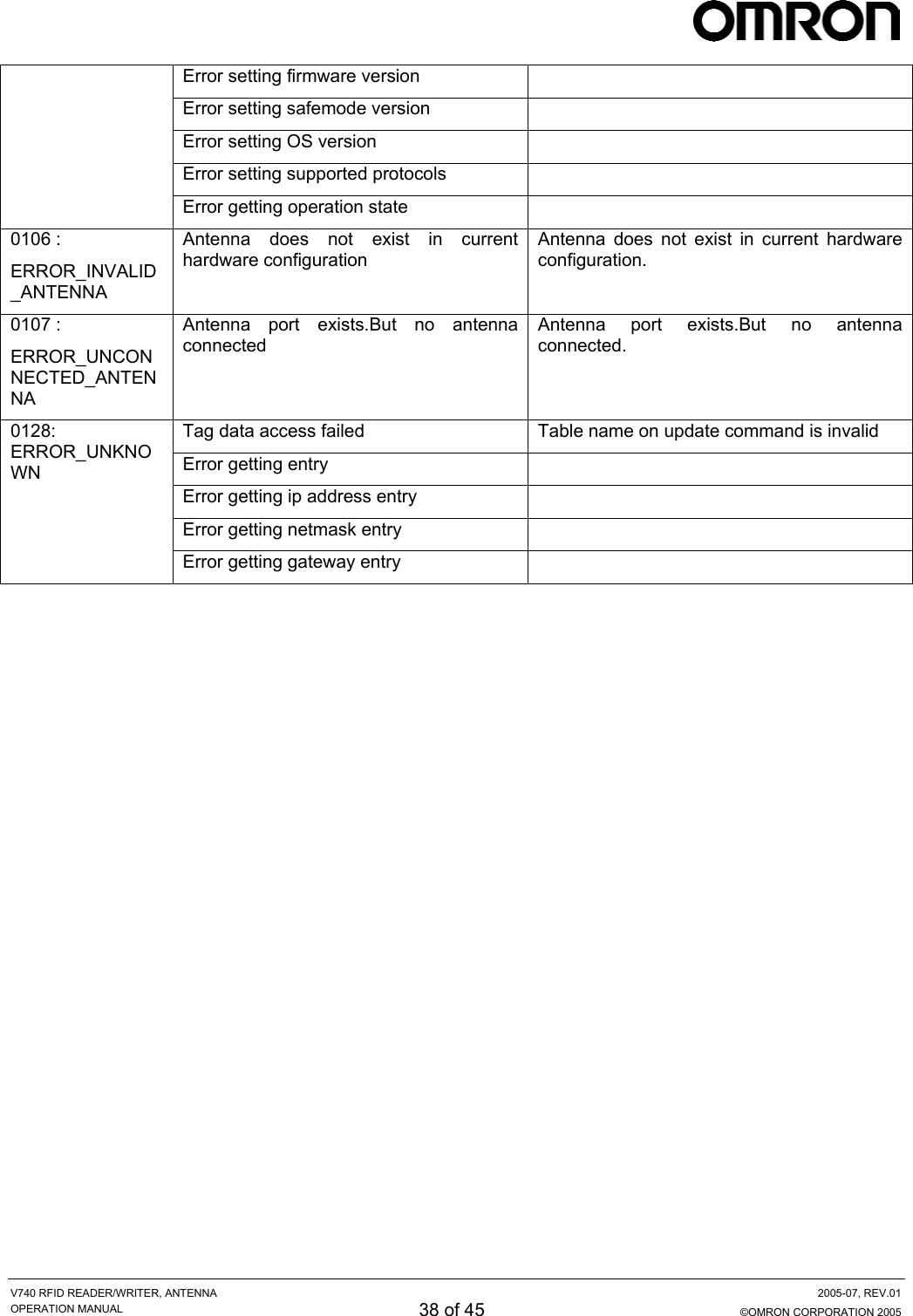
![V740 RFID READER/WRITER, ANTENNA 2005-07, REV.01 OPERATION MANUAL 29 of 45 ©OMRON CORPORATION 2005 2.2.4.2 ID Write The UPDATE command is used to write new data to a tag. This can be used to write a new tag_id. The structure of an UPDATE command is as follows: UPDATE table_expression set_specification where_specification; table_expression and entries specified in set_specification are provided in Table 3. A table_expression is specified by only one table name: UPDATE tag_id A set_specification is entered as: SET entry=value A where_specification is entered as: WHERE boolean_expr In a where_specification, both protocol_id and antenna_id must be specified. The tag_id (tag data) is returned with a check code as follows: EPC0: [id][check_code]<LF><LF> EPC1:[check_code][tag_id]<LF><LF> The 'where_specification' is specified in the same manner as the SELECT in the previous section.: • Example : To write tag data(tag_id) a 64-bit EPC tag: UPDATE tag_id SET id=0x1234567890ABCDEF WHERE protocol=’EPC1’ AND antenna_id=1; The reader returns the tag_id if the write operation was successful.For example the response is as follows: 0xCE851234567890ABCDEF<LF><LF> In this case, “CE85” is the check code. “1234567890ABCDEF” is tag data(tag id). If the operation is failed, "Error 0102: Error performing query<LF><LF>" returend. Note: The format of the tag data in the command must much the selected protocol or an error will result. For example : - A 64 bit EPC1 tag requires 16 hexadecimal digits - A 96 bit EPC1 tag requires 24 hexadecimal digits (See section 1.6) If wrong data is written to the tag, the tag may be unreadable. In this case, write correct tag ID again, after that, the tag would turn to be readable.](https://usermanual.wiki/Omron-RFID-Business-Development-Department/V740-BA50CX4/User-Guide-577901-Page-29.png)
![V740 RFID READER/WRITER, ANTENNA 2005-07, REV.01 OPERATION MANUAL 30 of 45 ©OMRON CORPORATION 2005 Table3 : Table Schema - Tag Write Keyword Entry Table Arguments Range Example Value Comments UPDATE tag_id - - - - Tag id data database table(fixed) SET id tag_id Hex String - 0xFEDCBA0987654321 Specifies the tag id(tag data) to be written antenna_id tag_id Int [1...4] 1 Specifies the antenna used to read a tag WHERE protocol_id tag_id String 'EPC1' 'EPC1' Specifies the protocol used to read a tag. Must be uppercase.](https://usermanual.wiki/Omron-RFID-Business-Development-Department/V740-BA50CX4/User-Guide-577901-Page-30.png)