Omron 6CYCIDV6400304 RF ID Transmitter User Manual users manual
Omron Corporation RF ID Transmitter users manual
Omron >
users manual

ÇÕǹÇ?Ç ëÊ 1 èÕ ëÊ 2 èÕ ëÊ 3 èÕ ëÊ 4 èÕ
INTRODUCTION
SECTION 1 SECTION 2 SECTION 3 SECTION 4 SECTION 5 SECTION 6
Introduction
SECTION 1
SECTION 2
SECTION 3
SECTION 4
SECTION 5
SECTION 6
Table of Contents/Precautions on Safety
Product Outline
Installation and Connections/Wiring
Preparing for Communications
Reading from/Writing to ID Tags
Troubleshooting
Appendix
CIDRW System
V640-HAM11 Amplifier Unit
V640-HS61 CIDRW Head
V700-L22 CIDRW Controller
V700-L11 Link Unit
User's Manual

2
22
2
INTRODUCTION
Warranty, Limitations of Liability, Application Considerations Disclaimers
CIDRW System
User’s Manual
INTRODUCTION
Warranty, Limitations of Liability, Application Considerations Disclaimers
Please read and understand this manual before storing, installing, programming, operating, maintaining, or disposing of
the products. Please consult your OMRON representative if you have any questions or comments.
OMRON's exclusive warranty is that the products are free from defects in materials and workmanship for a period of one
year (or other period if specified) from date of sale by OMRON.
OMRON MAKES NO WARRANTY OR REPRESENTATION, EXPRESS OR IMPLIED, REGARDING NON-
INFRINGEMENT, MERCHANTABILITY, OR FITNESS FOR PARTICULAR PURPOSE OF THE PRODUCTS. ANY
BUYER OR USER ACKNOWLEDGES THAT THE BUYER OR USER ALONE HAS DETERMINED THAT THE
PRODUCTS WILL SUITABLY MEET THE REQUIREMENTS OF THEIR INTENDED USE. OMRON DISCLAIMS ALL
OTHER WARRANTIES, EXPRESS OR IMPLIED.
OMRON SHALL NOT BE RESPONSIBLE FOR SPECIAL, INDIRECT, OR CONSEQUENTIAL DAMAGES, LOSS OF
PROFITS OR COMMERCIAL LOSS IN ANY WAY CONNECTED WITH THE PRODUCTS, WHETHER SUCH CLAIM IS
BASED ON CONTRACT, WARRANTY, NEGLIGENCE, OR STRICT LIABILITY.
In no event shall the responsibility of OMRON for any act exceed the individual price of the product on which liability is
asserted.
IN NO EVENT SHALL OMRON BE RESPONSIBLE FOR WARRANTY, REPAIR, OR OTHER CLAIMS REGARDING THE
PRODUCTS UNLESS OMRON'S ANALYSIS CONFIRMS THAT THE PRODUCTS WERE PROPERLY HANDLED,
STORED, INSTALLED, AND MAINTAINED AND NOT SUBJECT TO CONTAMINATION, ABUSE, MISUSE, OR
INAPPROPRIATE MODIFICATION OR REPAIR.
Read and Understand this Manual
WARRANTY
LIMITATIONS OF LIABILITY

3
33
3
CIDRW System
User’s Manual
INTRODUCTION
Warranty, Limitations of Liability, Application Considerations Disclaimers
INTRODUCTION
OMRON shall not be responsible for conformity with any standards, codes, or regulations that apply to the combination of
the product in the customer's application or use of the products.
At the customer's request, OMRON will provide applicable third party certification documents identifying ratings and
limitations of use that apply to the products. This information by itself is not sufficient for a complete determination of the
suitability of the products in combination with the end product, machine, system, or other application or use.
The following are some examples of applications for which particular attention must be given. This is not intended to be
an exhaustive list of all possible uses of the products, nor is it intended to imply that the uses listed may be suitable for the
products:
• Outdoor use, uses involving potential chemical contamination or electrical interference, or conditions or uses not
described in this manual.
• Nuclear energy control systems, combustion systems, railroad systems, aviation systems, medical equipment,
amusement machines, vehicles, safety equipment, and installations subject to separate industry or government
regulations.
• Systems, machines, and equipment that could present a risk to life or property.
Please know and observe all prohibitions of use applicable to the products.
NEVER USE THE PRODUCT FOR AN APPLICATION INVOLVING SERIOUS RISK TO LIFE OR PROPERTY WITHOUT
ENSURING THAT THE SYSTEM AS A WHOLE HAS BEEN DESIGNED TO ADDRESS THE RISKS, AND THAT THE
OMRON PRODUCTS ARE PROPERLY RATED AND INSTALLED FOR THE INTENDED USE WITHIN THE OVERALL
EQUIPMENT OR SYSTEM.
OMRON shall not be responsible for the user's programming of a programmable product, or any consequence thereof.
SUITABILITY FOR USE
PROGRAMMABLE PRODUCTS

4
44
4
INTRODUCTION
Warranty, Limitations of Liability, Application Considerations Disclaimers
CIDRW System
User’s Manual
INTRODUCTION
Warranty, Limitations of Liability, Application Considerations Disclaimers
Performance data given in this manual is provided as a guide for the user in determining suitability and does not constitute
a warranty. It may represent the result of OMRON's test conditions, and the users must correlate it to actual application
requirements. Actual performance is subject to the OMRON Warranty and Limitations of Liability.
Product specifications and accessories may be changed at any time based on improvements and other reasons.
It is our practice to change model numbers when published ratings or features are changed, or when significant
construction changes are made. However, some specifications of the product may be changed without any notice. When
in doubt, special model numbers may be assigned to fix or establish key specifications for your application on your
request. Please consult with your OMRON representative at any time to confirm actual specifications of purchased
product.
Dimensions and weights are nominal and are not to be used for manufacturing purposes, even when tolerances are
shown.
The information in this document has been carefully checked and is believed to be accurate; however, no responsibility is
assumed for clerical, typographical, or proofreading errors, or omissions.
PERFORMANCE DATA
CHANGE IN SPECIFICATIONS
DIMENSIONS AND WEIGHTS
ERRORS AND OMISSIONS

5
CIDRW System
User’s Manual
INTRODUCTION
Precautions for Safe Use
INTRODUCTION
Applicable Standards
1. FCC Rules (Federal Communications Commission)
This device complies with Part 15 Subpart C of the FCC Rules.
FCC ID: E4E6CYCID6400202
Operation is subject to the following two conditions:
(1) this device may not cause harmful interference, and
(2) this device must accept any interference received, including interference that may cause undesired oper-
ation.
FCC NOTICE
This equipment has been tested and found to comply with the limits for a Class B digital device, pursu-
ant to part 15 of the FCC Rules. These limits are designed to provide reasonable protection against
harmful interference in a residential installation.
This equipment generates, uses and can radiate radio frequency energy and, if not installed and used
in accordance with the instructions, may cause harmful interference to radio communications. How-
ever, there is no guarantee that interference will not occur in a particular installation. If this equipment
does cause harmful interference to radio or television reception, which can be determined by turning
the equipment off and on, the user is encouraged to try to correct the interference by one or more of
the following measures:
• Reorient or relocate the receiving antenna
• Increase the separation between the equipment and receiver.
• Connect the equipment into an outlet on a circuit different from that to which the receiver is
connected.
• Consult the dealer or an experienced radio/TV technician for help.
FCC WARNING
Changes or modifications not expressly approved by the party responsible for compliance could void
the user's authority to operate the equipment.
Properly shielded and grounded cables and connectors must be used for connection to host
computer and/or peripherals in order to meet FCC emission limits.
CAUTION
This device must be professionally installed.
This CIDRW Head [Model: V640-HS61 (-X)] is dedicated to Amplifier Unit [Model: V640-HAM11 (-X)].
E4E6CYCIDV6400304
Do not remove the ferrite core on the cable of the CIDRW head.

7
CIDRW System
User’s Manual
INTRODUCTION
Precautions for Safe Use
INTRODUCTION
Applicable SEMI Standards
This CIDRW system complies with the following standards.
• SEMI E99 THE CARRIER ID READER/WRITER FUNCTIONAL STANDARD
• SEMI E5 EQUIPMENT COMMUNICATION STANDARD 2 MESSAGE CONTENT (SECS II)
• SEMI E4 EQUIPMENT COMMUNICATION STANDARD 1 MESSAGE TRANSFER (SECS I)
SEMI is the acronym for Semiconductor Equipment and Materials International.
SECS is the acronym for SEMI Equipment Communications Standard.

8
INTRODUCTION
Precautions for Safe Use
CIDRW System
User’s Manual
INTRODUCTION
Please observe the following precautions for safe use of the products.
• Do not insert water or wires through gaps in the case. This could cause fire or electric shock.
• In the event of a malfunction, stop using the product immediately, turn off the power, and consult your
OMRON dealer.
• Dispose of this product as industrial waste.
Precautions for Safe Use

9
CIDRW System
User’s Manual
INTRODUCTION
Precautions for Safe Use
INTRODUCTION
Please observe the following precautions to prevent failure to operate, malfunctions, or undesirable effects on
product performance.
Installation Site
Install the product at a location where:
• It is not exposed to direct sunlight.
• It is not exposed to corrosive gases, dust, metal chips, or salt.
• The working temperature is within the range stipulated in the specifications.
• There are no sudden variations in temperature (no condensation).
• The relative humidity is within the range stipulated in the specifications.
• No vibration or shock exceeding the values stipulated in the specifications is transmitted directly to
the body of the product.
• It is not subject to splashing water, oil, or chemical substances.
Mounting
• This product communicates with ID Tags using the 134 kHz frequency band. Note that some trans-
ceivers, motors, monitoring equipment, and power supplies (power supply ICs) generate electrical
waves (noise) that interfere with communications with ID Tags. If you are using the product in the
vicinity of any of these devices, check the effect on communications in advance.
• In order to minimize the effects of noise, ground nearby metal bodies with a grounding resistance not
exceeding 100 ohms.
• When mounting Amplifier Units, tighten the screws with a torque no greater than 1.2 N·m.
• When mounting CIDRW Heads, tighten the screws with a torque no greater than 0.6 N·m.
• When multiple CIDRW Heads are mounted next to each other, communications performance could
be impaired by mutual interference. Note the information in this manual on mutual interference when
installing multiple heads.
Refer to page 115.
Precautions for Correct Use

10
INTRODUCTION
Precautions for Safe Use
CIDRW System
User’s Manual
INTRODUCTION
Power and Ground Cables
• Use the power supply voltage specified in this manual.
• Ensure correct polarity when connecting to the +/- power supply terminals.
• The ground terminals must be connected to a ground with a grounding resistance not exceeding 100
ohms.
Wiring Work
• Always turn the power off before starting wiring work or connecting/disconnecting cables.
• Do not run high-voltage lines and power lines though the same conduit.
• To prevent damage by static electricity, wear a wrist strap or equivalent, and take measures to pre-
vent charging, before touching terminal components or parts inside connectors.
Screw Locking Adhesive
• Screw locking adhesive (screw lock) may cause deterioration and cracking of resin parts: do not use
it for screws in resin parts or anywhere where resin washers are used.
Cleaning
• Do not use organic solvents such as thinner or benzene.

11
CIDRW System
User’s Manual
INTRODUCTION
Precautions for Safe Use
INTRODUCTION
Editor’s Note
Visual Aids
Indicates an explanation of a point that must be observed to ensure that the product is capable of its proper functions and perfor-
mance. Read this information carefully and follow the cautions: if the product is used incorrectly, data or the equipment itself
could be destroyed.
Indicates summaries of points of particular importance relating to product performance, e.g. points to note during operation and
advice on how to use the product.
Indicates the number of a page where related information can be found.
Indicates information for reference when you encounter a problem.
Indicator Statuses
The following symbols are used to show the status of the indicators on the CIDRW Controller and Amplifier
Units.
OFF
Flashing
ON

12
INTRODUCTION
Table of Contens
CIDRW System
User’s Manual
INTRODUCTION
Table of Contents
Table of Contents
Introduction 3
Read and Understand this Manual 2
WARRANTY 2
LIMITATIONS OF LIABILITY 2
SUITABILITY FOR USE 3
PROGRAMMABLE PRODUCTS 3
PERFORMANCE DATA 4
CHANGE IN SPECIFICATIONS 4
DIMENSIONS AND WEIGHTS 4
ERRORS AND OMISSIONS 4
Applicable Standards 5
Applicable SEMI Standards 7
Precautions for Safe Use 8
Precautions for Correct Use 9
Editor’s Note 11
Table of Contents 12
SECTION 1 Product Outline 15
What is a CIDRW System? 16
Features 17
System Configuration 18
Component Names and Functions 19
Flowchart for Getting Started 23
SECTION 2 Installation and Connections/Wiring 25
Installation 26
Connections and Wiring 31
SECTION 3 Preparing for Communications 47
Set the Communications Conditions for the CIDRW Controller 48
Set the Communications Conditions for Amplifier Units 61
Set the Communications Conditions for Link Units 63
Communications Test 65

13
CIDRW System
User’s Maual
INTRODUCTION
Table of Contents
INTRODUCTION
Table of Contents
SECTION 4 Reading from/Writing to ID Tags 69
When SECS is Used 70
When SECS is Not Used 81
SECTION 5 Troubleshooting 91
When SECS is Used 92
When SECS is Not Used 98
SECTION 6 Appendix 103
Specifications and Dimensions 104
System Configuration Examples 108
Characteristic Data depending on Conditions of Use 110
Data Segment Area 122
Regular Inspection 123
SECS Protocol Specifications 124
ASCII Code Table 129
Protective Construction 130
Revision History 134

14
INTRODUCTION
Table of Contens
CIDRW System
User’s Manual
INTRODUCTION
Table of Contents
MEMO

16
SECTION 1
What is a CIDRW System?
CIDRW System
User’s Manual
SECTION 1
Product Outline
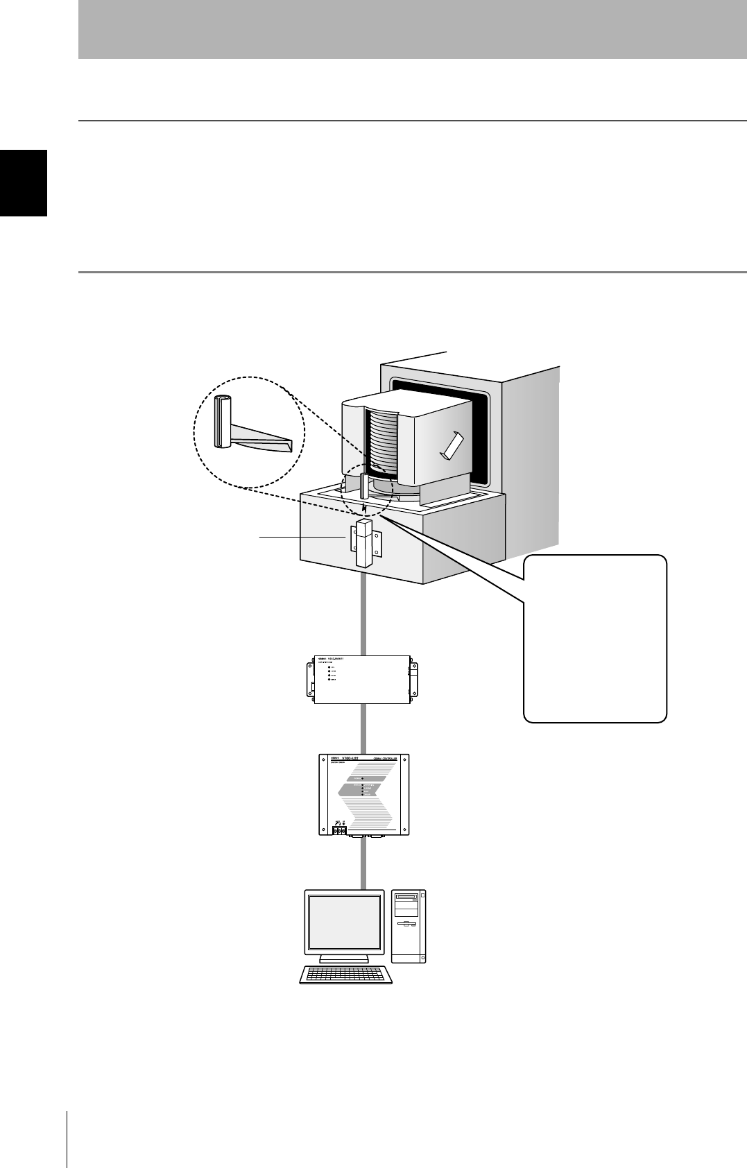
What is a CIDRW System?
The CIDRW system writes data to, and reads data from, the carrier IDs (ID Tags) mounted on the carriers
(FOUP) in semiconductor manufacturing processes without contacting these ID Tags. CIDRW is the
abbreviation of "Carrier ID Reader/Writer" and this abbreviation is used throughout this manual.
Reading and writing information such as models, process instructions, lots, and inspection results to and from
ID Tags makes it possible to manage work instruction information from a host device.
Example: Management of information in semiconductor and wafer manufacturing processes
ID Tag
(holder is separate)
CIDRW Head
Reading and writing
information
• Model information
• Process instruction
information
• Completion
information
• Lot information
• Inspection results
Etc.
Host
Amplifier Unit
CIDRW Controller
17
CIDRW System
User’s Maual
SECTION 1
Features
SECTION 1
Product Outline
Features
CIDRW Systems that Conform to SEMI Standards (SEMI E99, E5, E4)
List of Applicable Standards
• SEMI E99 THE CARRIER ID READER/WRITER FUNCTIONAL STANDARD
• SEMI E5 EQUIPMENT COMMUNICATION STANDARD 2 MESSAGE CONTENT (SECS II)
• SEMI E4 EQUIPMENT COMMUNICATION STANDARD 1 MESSAGE TRANSFER (SECS I)
SEMI is the acronym for Semiconductor Equipment and Materials International.
SECS is the acronym for SEMI Equipment Communications Standard.
Host
SECS I/II
CIDRW Controller
V700-L22
Amplifier Unit
V640-HAM11
CIDRW Head
V640-HS61
ID Tag
RI-TRP-DR2B
(Made by Texas
Instruments)
CIDRW System Conforming to SEMI Standards
RS-232C RS-232C
18
SECTION 1
System Configuration
CIDRW System
User’s Manual
SECTION 1
Product Outline
System Configuration
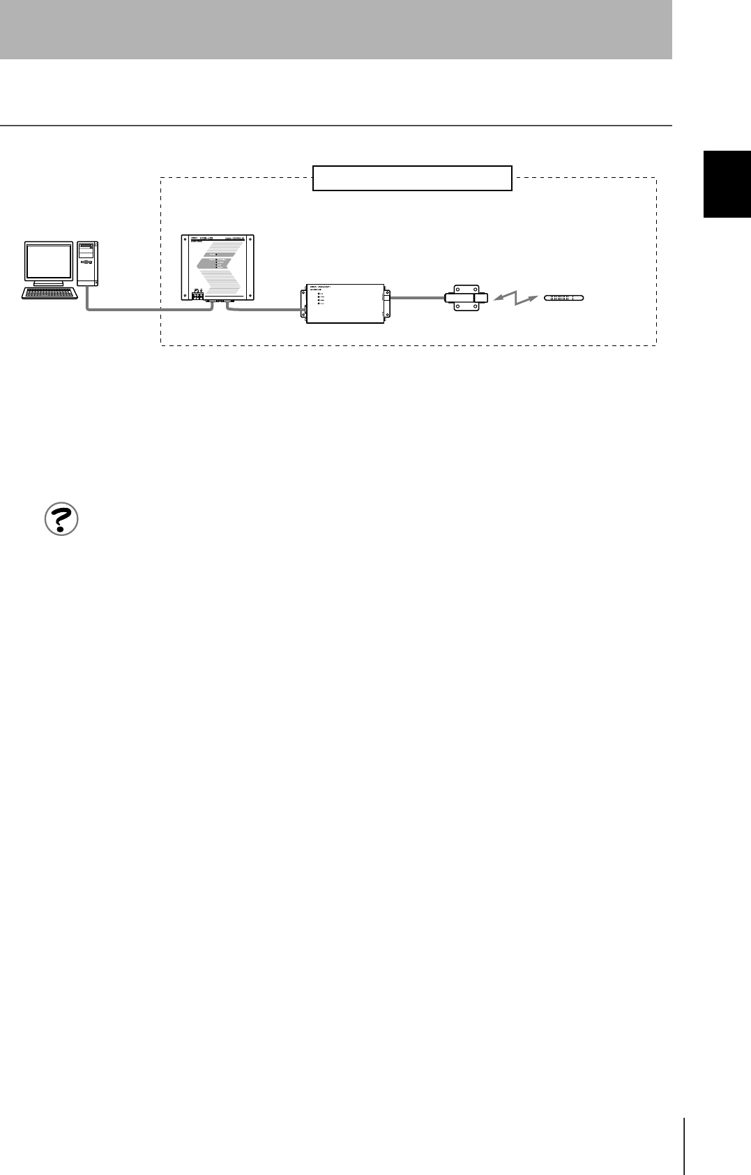
When SECS is Used
Communication with the host device is possible using the SECS protocol.
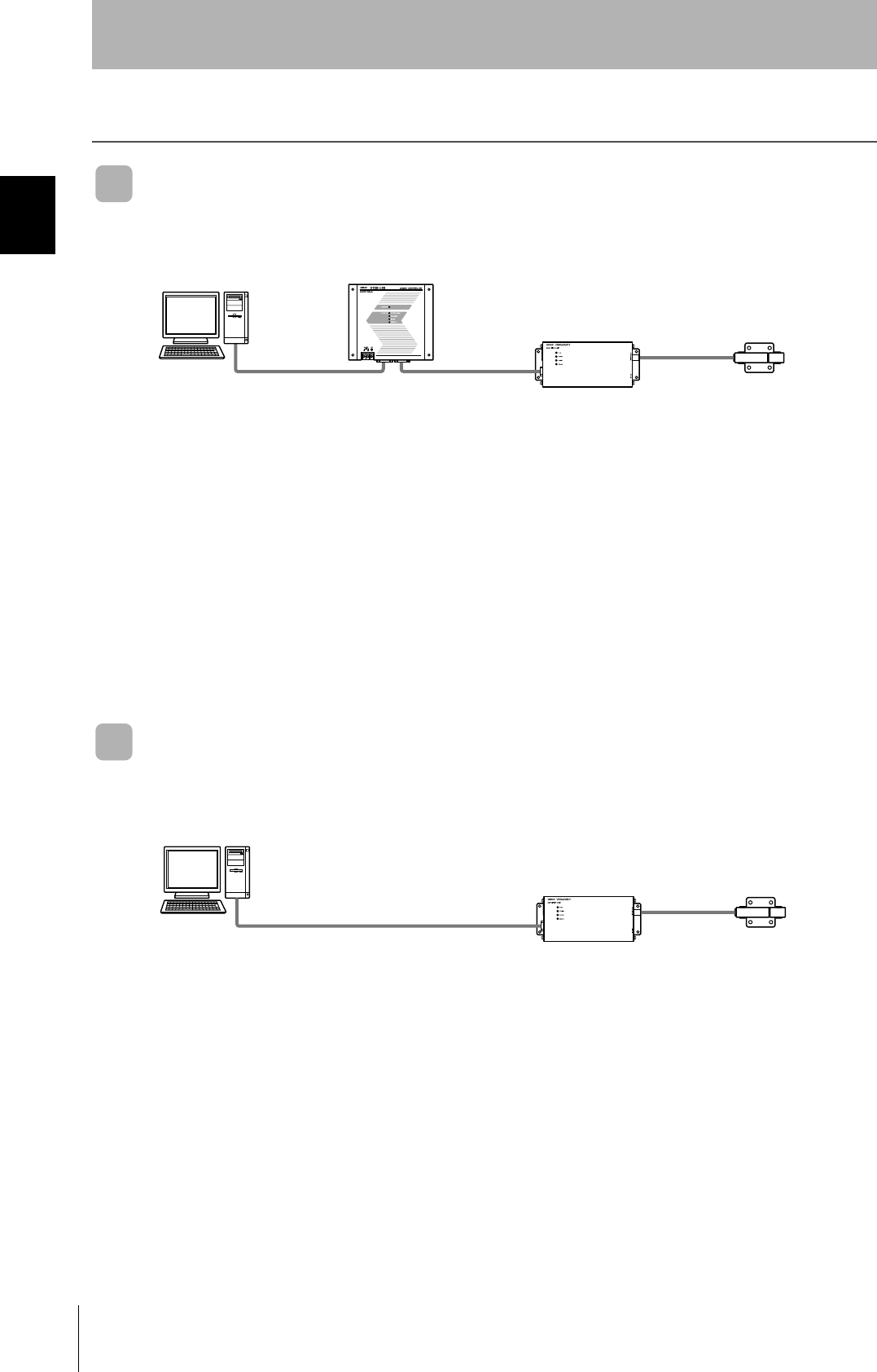
When SECS is Not Used
Communications with the host device follow the OMRON proprietary protocol.
The Amplifier Units are connected directly to the host device without using a CIDRW Controller.
These are antennae for
reading the carrier IDs
from the ID Tags and
writing the carrier IDs.
These are units that
control a CIDRW Head.
This is e.g. a host,
or equipment con-
troller.
CIDRW Head
V640-HS61
Amplifier Unit
V640-HAM11
CIDRW Controller
V700-L22
Host
Multiple Amplifier Units
are controlled in
response to commands
(SECS) from the host
device.
RS-232C
SECS I/II RS-232C
These are antennae for
reading the carrier IDs
from the ID Tags and
writing the carrier IDs.
These are units that
control a CIDRW Head.
This is e.g. a host,
or equipment con-
troller.
CIDRW Head
V640-HS61
Amplifier Unit
V640-HAM11
Host
RS-232C
OMRON proprietary protocol
19
CIDRW System
User’s Maual
SECTION 1
Component Names and Functions
SECTION 1
Product Outline
Component Names and Functions
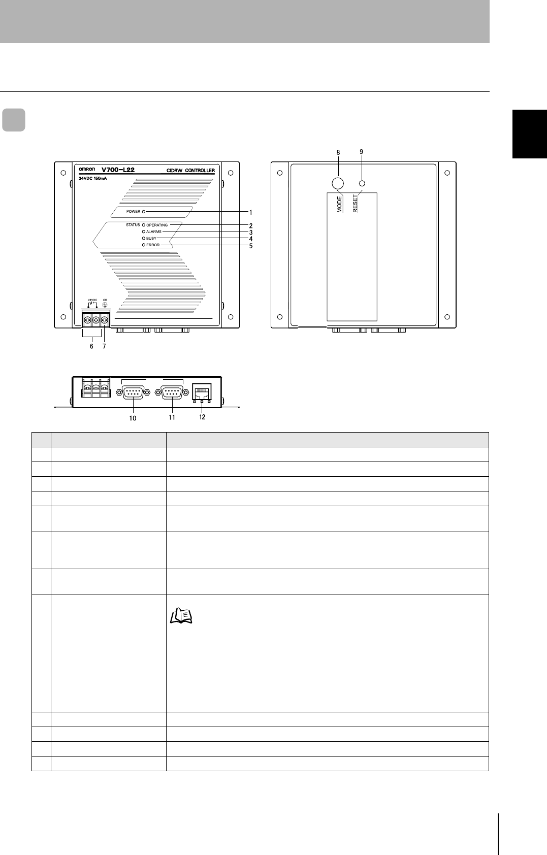
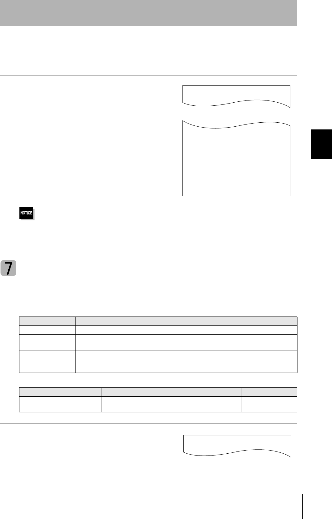
CIDRW Controller V700-L22
No. Name Function
1 Power indicator (green) An LED that indicates whether the power is ON or OFF. Lit while the power is ON.
2 OPERATING indicator (green) Lit while the CIDRW system status model is operating.
3 ALARMS indicator (green) Lit when the status of "AlamStatus" of the CIDRW system is "Alarm (1)."
4 BUSY indicator (green) Lit when the status of "OparationalStatus" of the CIDRW system is "BUSY."
5 ERROR indicator (red) When a processing error is detected (when SSACK is other than "NO"), this indicator is
lit for 50 ms.
6 24 VDC power supply termi-
nals
(with cover)
Connect to the 24 VDC power supply.
7 Frame ground terminal
(with cover)
The grounding wire is connected here. (Ground to 100 Ω or less)
8 MODE switch Used to select the mode of operation.
Refer to page 48.
0 : Normal Operation mode. When mounting the Controller, set the switch to this posi-
tion.
3 : Setting mode, selected to set information such as the communication conditions.
When the switch on the bottom face of the Controller cannot be accessed, the opera-
tion mode can be changed from the host device while the switch is left at the "0" set-
ting.
1 - 2, 4 - 7 : Setting prohibited
9 RESET switch Restarts the CIDRW Controller.
10 SECS port Port for connecting the host device. Conforms to SECS I/II.
11 ID port An Amplifier Unit or Link Unit is connected here.
12 Maintenance port (with cover) Not used. Do not remove the cover.
45%
5'%5 +& /#+06'0#00%'
20
SECTION 1
Component Names and Functions
CIDRW System
User’s Manual
SECTION 1
Product Outline
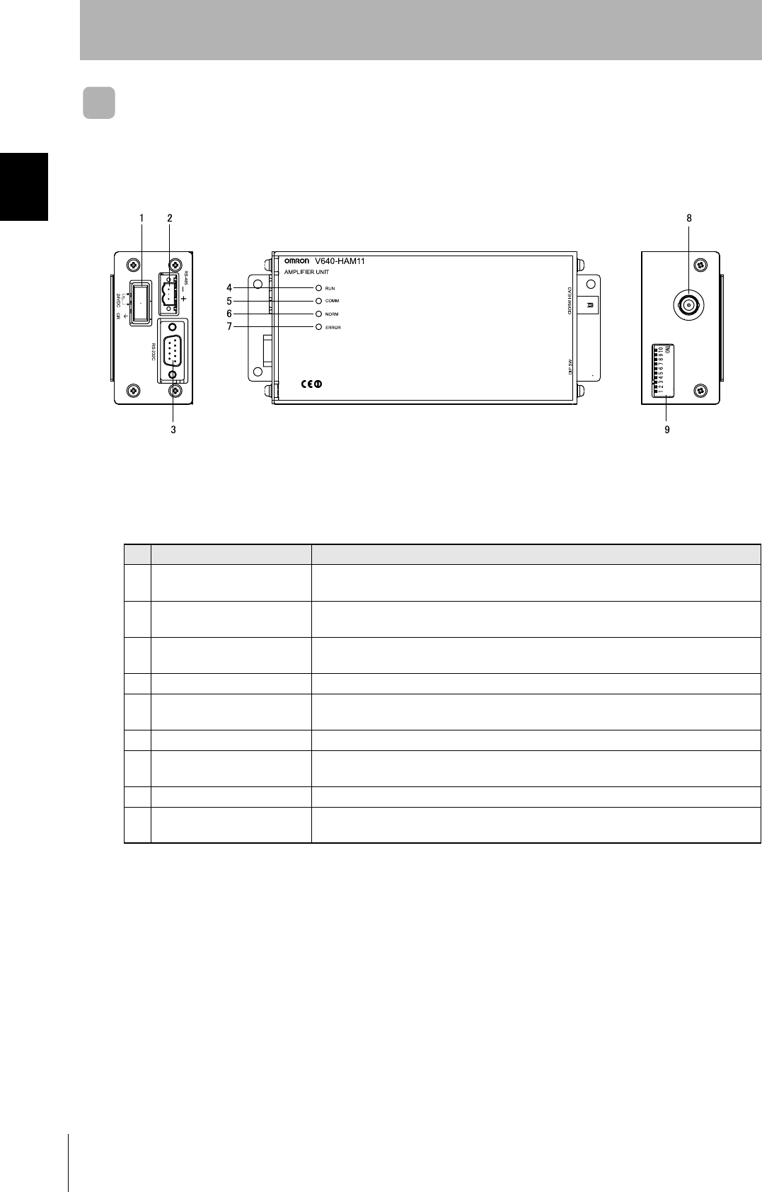
Amplifier Unit V640-HAM11
No. Name Function
1 Dedicated power supply con-
nector
Connect to the 24 VDC power supply.
2 RS-485 port When using multiple CIDRW Heads, connect this to the RS-485 port of another Amplifier
Unit or to the multi-connection port of a Link Unit.
3 RS-232C port Connected to a CIDRW Controller or a host device.
Uses the OMRON proprietary communications protocol.
4 RUN indicator (green) Turns ON when the Amplifier Unit is in normal operation.
5 COMM indicator (yellow) Turns ON during communications with the host device or during communications with an
ID Tag.
6 NORM indicator (green) Turns ON when the communications finish with no error.
7 ERROR indicator (red) Turns ON when an error occurs during communication with the host device, or during
communication with an ID Tag.
8 CIDRW Head connection port A CIDRW Head is connected here.
9 Setting DIP switches Used to set the node number, the communications conditions, and the RS-485 terminal
resistance.
21
CIDRW System
User’s Maual
SECTION 1
Component Names and Functions
SECTION 1
Product Outline
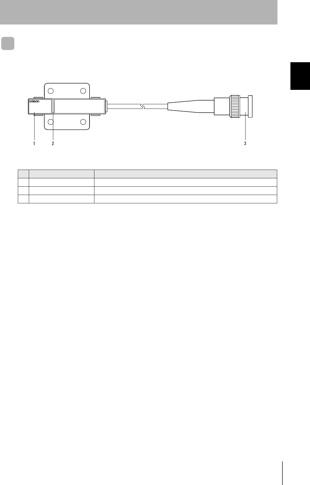
CIDRW Head V640-HS61
No. Name Function
1 Antenna Used to communicate with ID Tags.
2 Antenna center This is the center of the communications area.
3 Connector Connect to an Amplifier Unit.
V640-HS61
CIDRW HEAD
22
SECTION 1
Component Names and Functions
CIDRW System
User’s Manual
SECTION 1
Product Outline
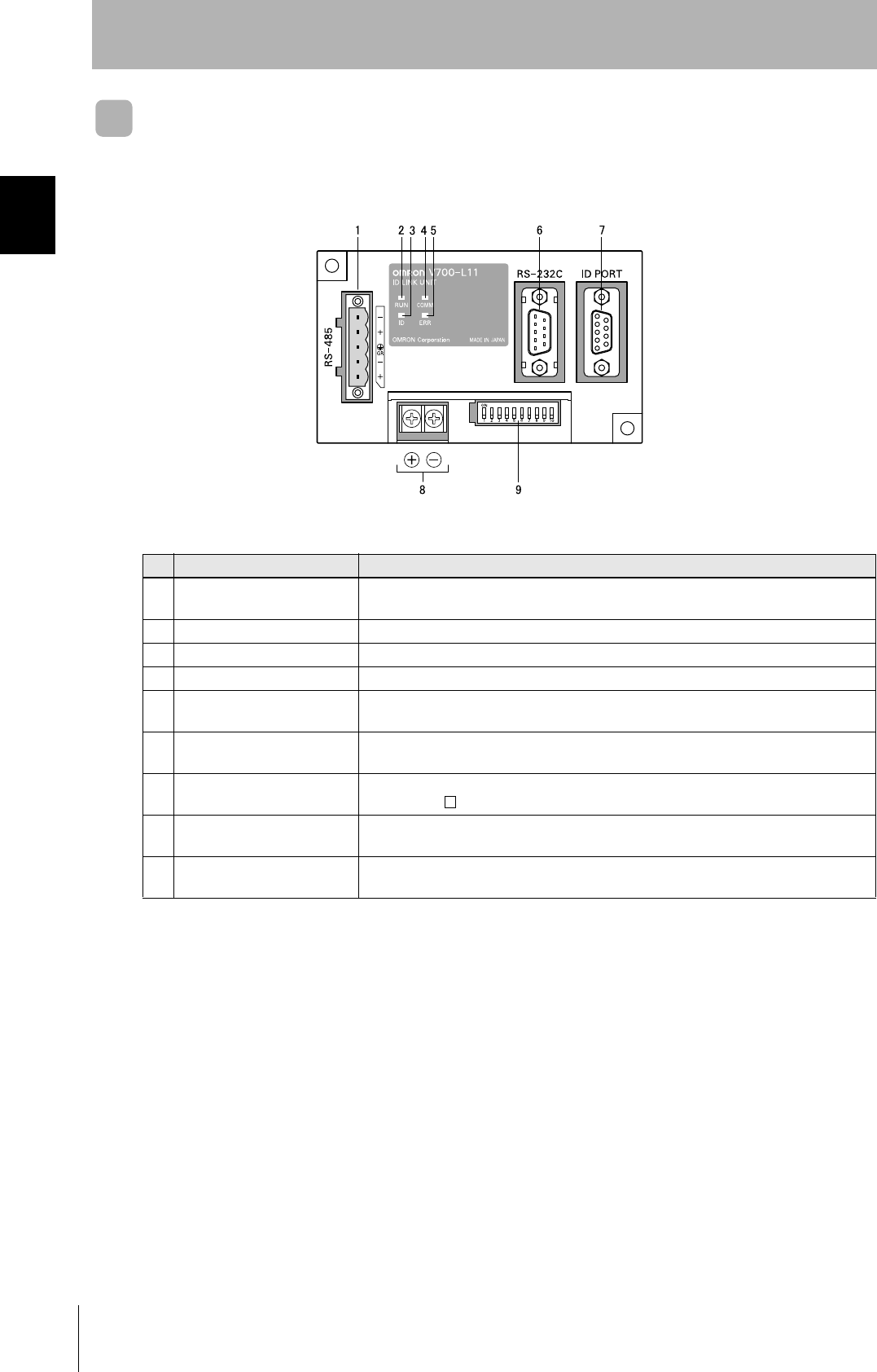
Link unit V700-L11
No. Name Function
1 Multi-connection port
(RS-485)
This is the port that connects to the Amplifier Units when multiple CIDRW Heads are
connected to a CIDRW Controller. The GR (frame ground) terminal is also at this port.
2 RUN indicator (green) Turns ON while the Link Unit is in normal operation.
3 ID indicator (green) Turns ON during data communications with a V700 series IDRW Head.
4 COMM indicator (green) Turns ON during data communications with the host device.
5 ERR indicator (red) Turns ON when an error occurs during data communications with the host device or
head.
6 Host device connection port
(RS-232C)
This is a port for connecting to the CIDRW Controller via an RS-232C interface. A dust
cover is fitted on shipment from the factory. Remove this cover before using the port.
7 ID connection port This is a dedicated port for connecting a V700 series IDRW Head. Connect either a
V700-HMD13 or V700-HMD11-1 IDRW Head.
8 24 V power supply terminals
(inside the cover)
Connect to the 24 VDC power supply.
9 Setting DIP switches
(inside the cover)
Used to set the equipment number, the communications conditions, and the RS-485 ter-
minal resistance.
23
CIDRW System
User’s Maual
SECTION 1
Flowchart for Getting Started
SECTION 1
Product Outline
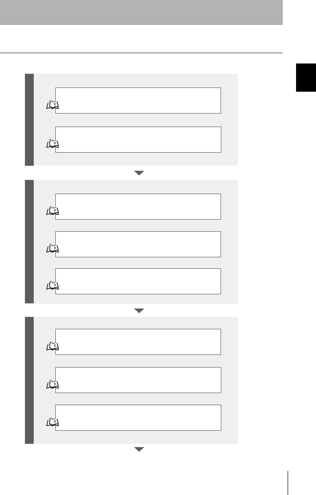
Flowchart for Getting Started
Refer to page 26.
Refer to page 31.
Refer to page 48.
Refer to page 61.
Refer to page 65.
Refer to page 66.
Installation
Connection and Wiring
Set the Communications Conditions for the CIDRW Controller
Set the Communications Conditions for Amplifier Units
Refer to page 63.
Set the Communications Conditions for Link Units
Test for Communications with the Host Device
ID Tag <-> CIDRW System Communications Test
Check the Surrounding Environment
Refer to page 28.
Preparation for CommunicationsTrial Operation Installation and Connections
24
SECTION 1
Flowchart for Getting Started
CIDRW System
User’s Manual
SECTION 1
Product Outline
Refer to page 70.
Refer to page 81.
Refer to page 92. List of Error Messages
Refer to page 92. Controller Indicators
Refer to page 93. Operation Check Flowchart
Refer to page 98. List of Error Messages
Refer to page 98. Amplifier Unit Indicators
Refer to page 99. Operation Check Flowchart
When SECS is Used
When SECS is Not Used
When SECS is Not Used
When SECS is Used
When you Encounter a Problem...
Communications

26
SECTION 2
Installation
CIDRW System
User’s Manual
SECTION 2
Installation and Connections/Wiring
Installation
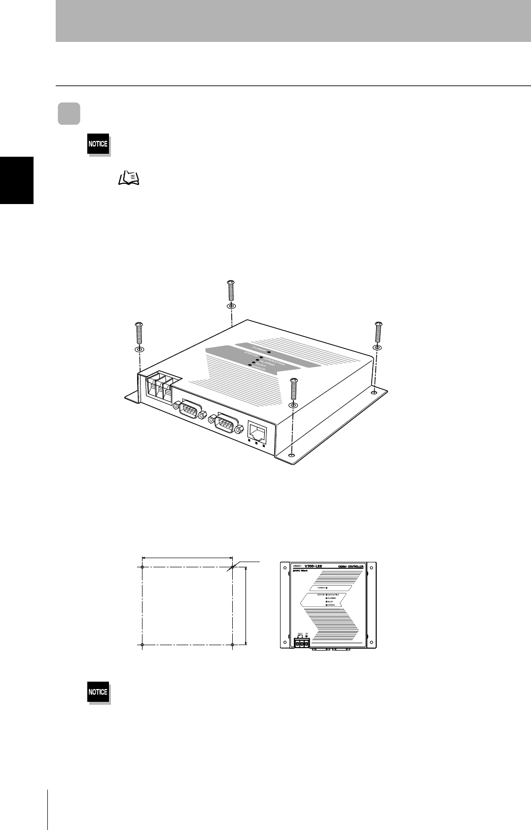
CIDRW Controller
There is a switch for selecting the operation mode (Normal Operation mode <-> Setting mode) on the bottom face of the
CIDRW Controller. Set the communications conditions in the Setting mode (switch position 3) before mounting the
CIDRW Controller.
Refer to page 48.
Set the Controller to the Normal Operation mode (switch position 0) when mounting it.
Mount the CIDRW Controller with the resin washers and four M4 screws provided as accessories.
•Tighten the M4 screws with a torque not exceeding 1.2 N·m.
• Do not apply organic solvents used with screw locking agents at the locations where the screws are inserted.
r
r /
Mounting dimensions
(Unit: mm)
27
CIDRW System
User’s Manual
SECTION 2
Installation
SECTION 2
Installation and Connections/Wiring
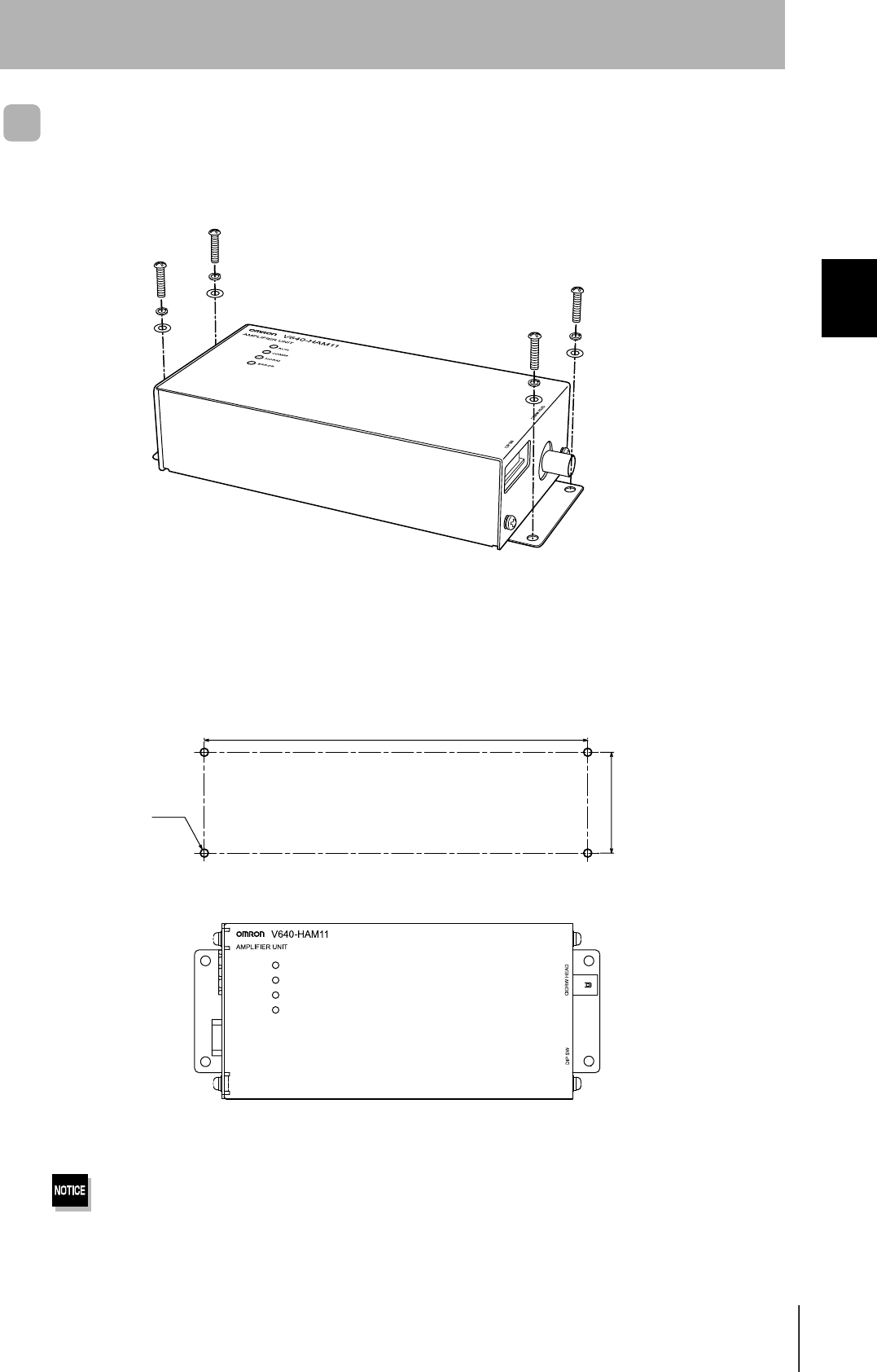
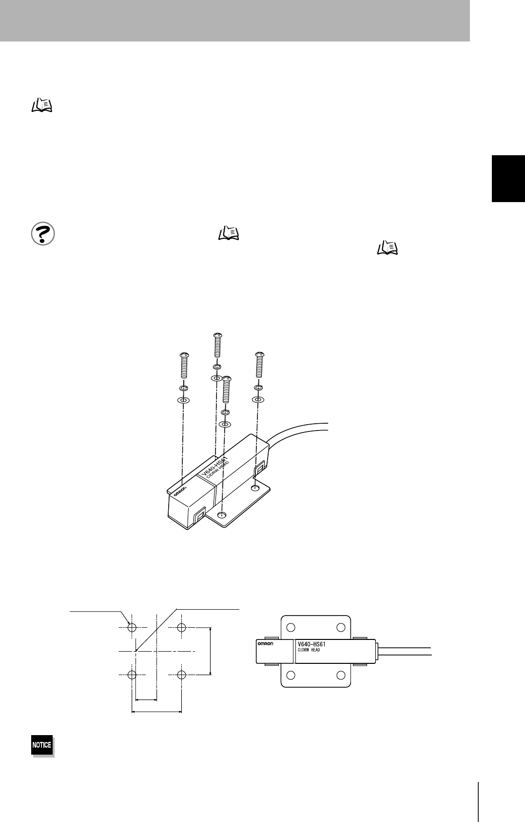
Amplifier Unit
Use spring washers and flat washers with the four M4 screws when mounting the Amplifier Unit.
Tighten the M4 screws with a torque not exceeding 1.2 N·m.
r
r
/
RUN
COMM
NORM
ERROR
Mounting dimensions
(Unit: mm)
28
SECTION 2
Installation
CIDRW System
User’s Manual
SECTION 2
Installation and Connections/Wiring
CIDRW Head
The area for communications with ID Tags varies substantially according to the installation orientations
and the background conditions (metals, noise, etc.). Check the communications area before deciding
the installation position.
For details on actual communications distances, see Characteristic Data depending on Conditions of
Use in Appendix.
Refer to page 109.
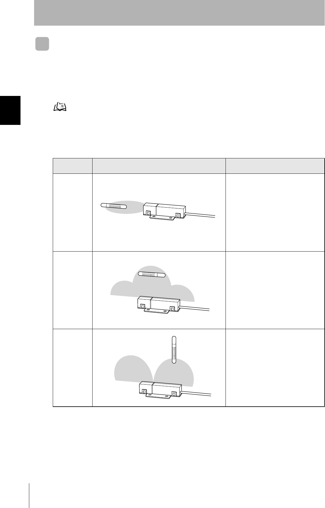
Positional Relationship between the CIDRW Head and the ID Tag
The communications area differs according to the positional relationship during communications.
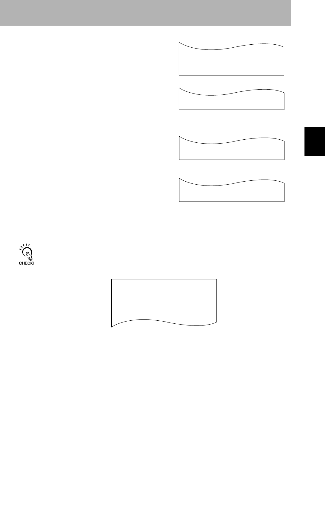
Data Reading and Writing
The communications distances for reading and writing are not the same; the distance is shorter for
writing. Therefore, when data is to be both read and written, take the distance for writing as the refer-
ence distance when installing the CIDRW Head and the ID Tag.
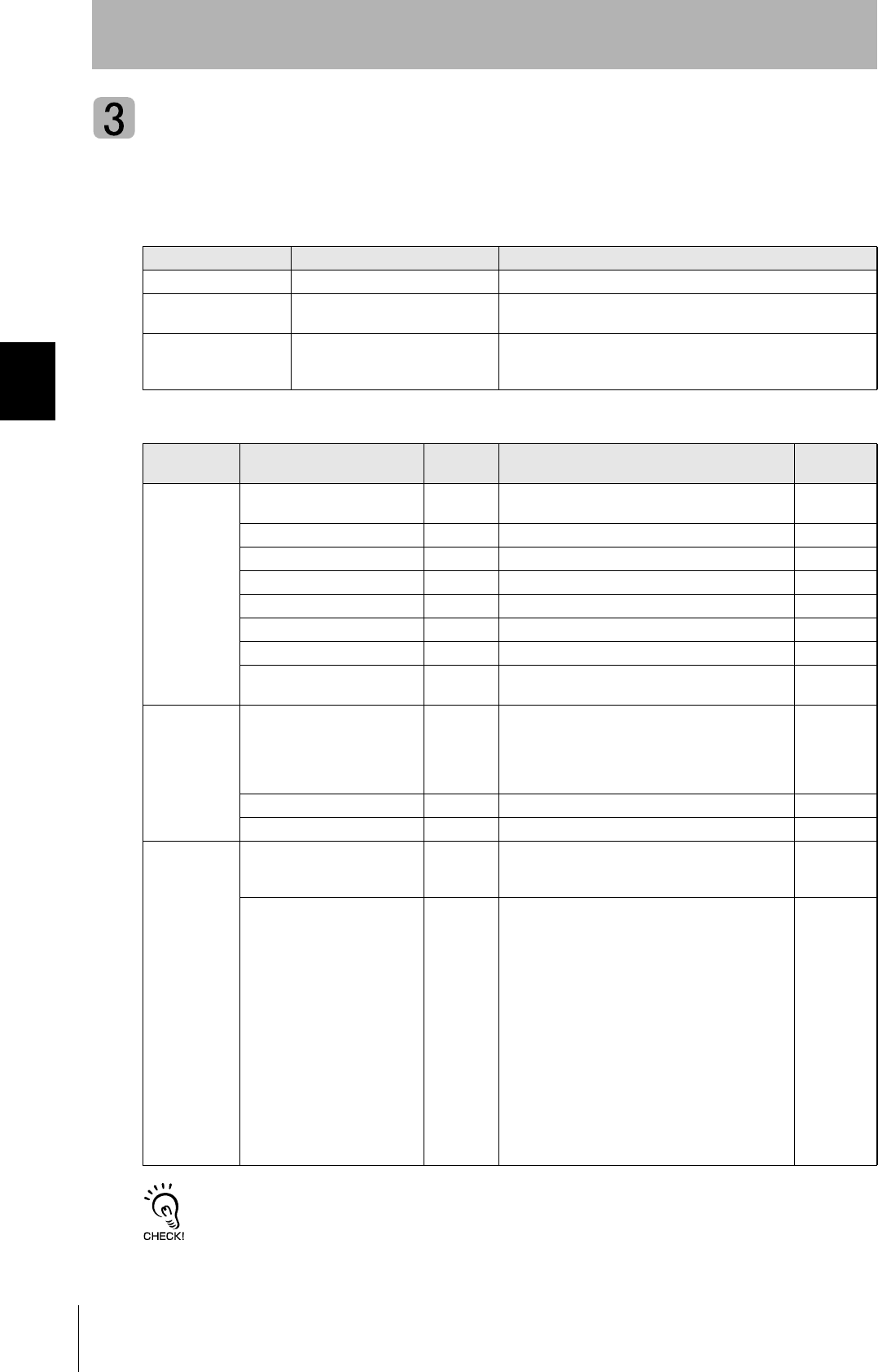
Mounting
orientation Communications area (purely illustrative) Explanation
Coaxial The maximum communications area is
obtained when the centerlines of the CIDRW
Head and the ID Tag coincide.
Parallel The maximum communications area is
obtained when the center point of the
antenna on the CIDRW Controller is aligned
with the centerline of the ID Tag.
Vertical When the center point of the antenna on the
CIDRW Head is aligned with the centerline of
the ID Tag, the communications area is sub-
stantially reduced.
29
CIDRW System
User’s Manual
SECTION 2
Installation
SECTION 2
Installation and Connections/Wiring
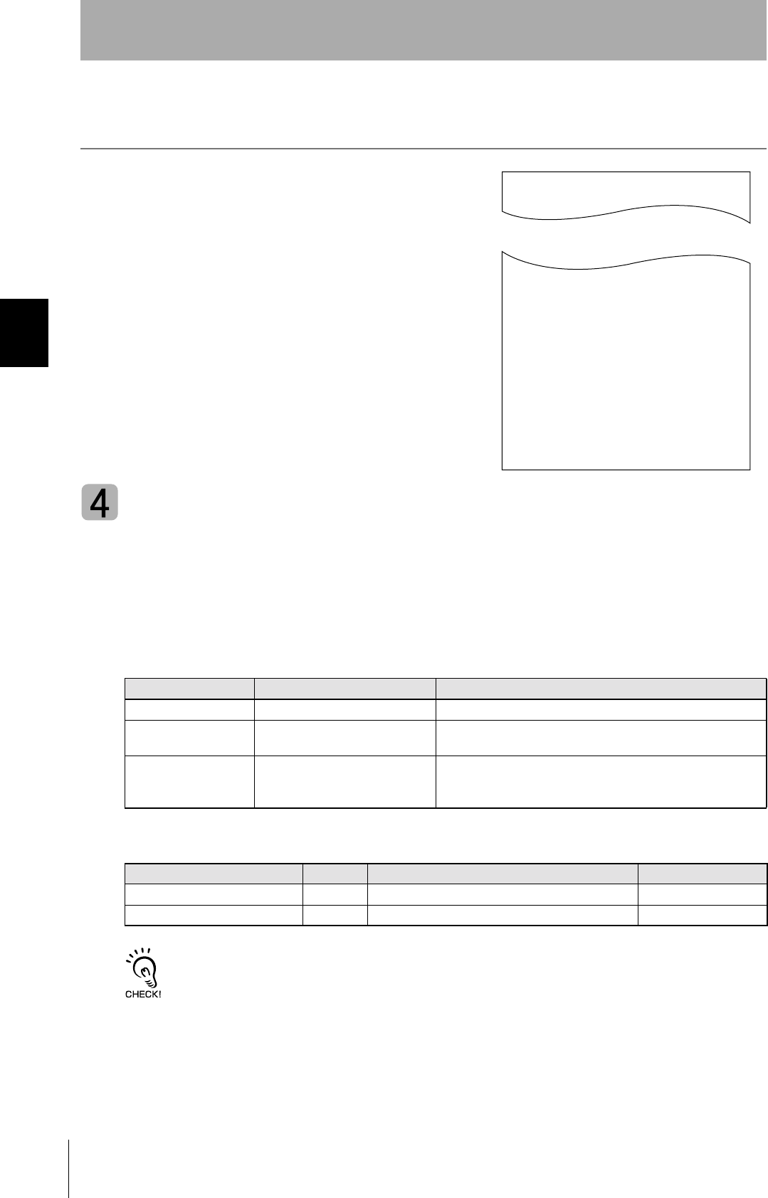
Influence of Background Metal on ID Tag
Metals in the vicinity of the communications area will affect the range, making it smaller.
Refer to page 115.
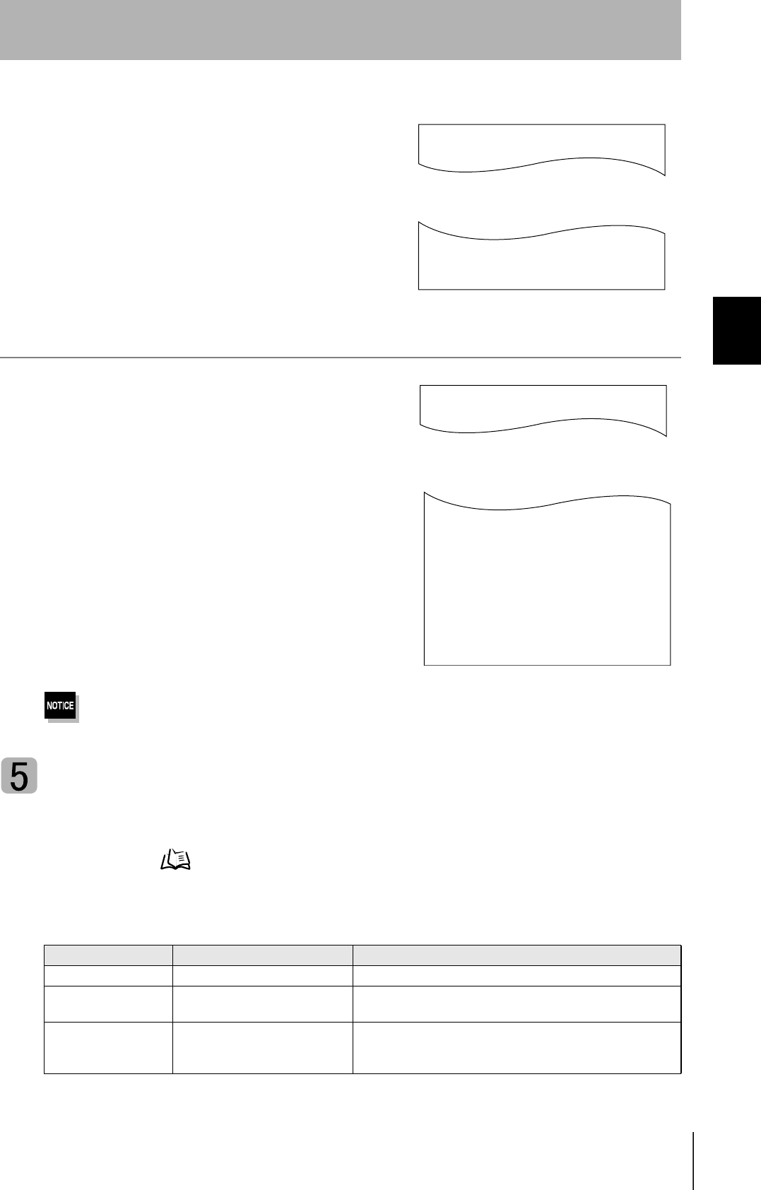
Influence of Noise
This CIDRW system uses a frequency of 134 kHz for communications with ID Tags. Equipment such
as switching power supplies, inverters, servomotors, or monitors in the surrounding area will adversely
affect communications, restricting the communications area.
The noise levels in the vicinity of the CIDRW Head can be determined with the environmental noise measurement com-
mand (applies only when SECS is not used). Refer to page 89.
For details on the relationship between noise and communications distance, see Appendix. Refer to page 121.
Mounting
Use spring washers and flat washers with the four M3 screws when mounting a CIDRW Head.
Tighten the M3 screws with a torque not exceeding 0.6 N·m.
Be sure to install the Amplifier Unit in a panel or metal-shielded equipment.
r
r
/14Ǿ
Mounting dimensions
(Unit: mm)
Antenna center
30
SECTION 2
Installation
CIDRW System
User’s Manual
SECTION 2
Installation and Connections/Wiring
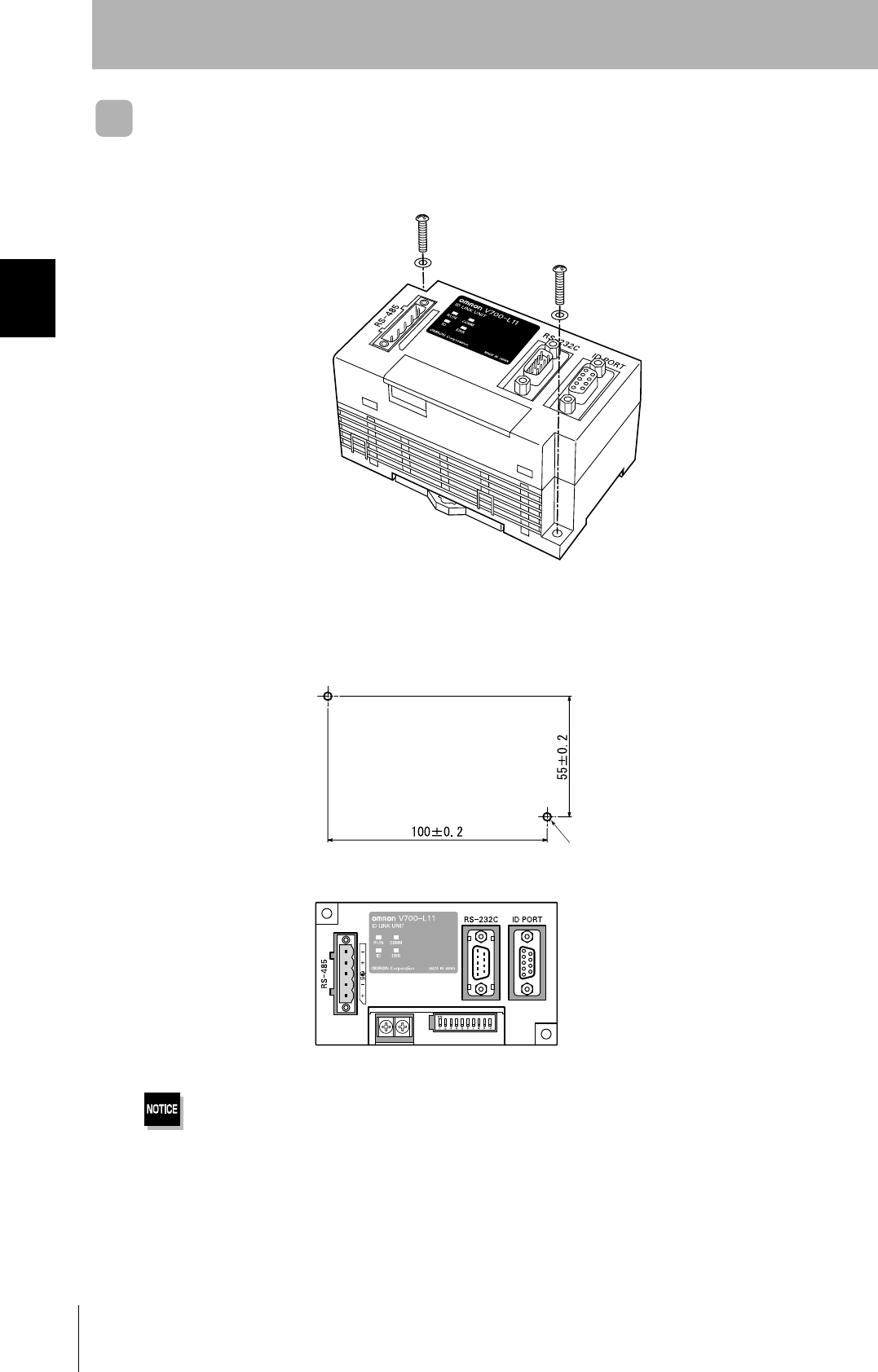
Link Unit
Mount Link Units with the two M4 screws and washers provided as accessories.
•Tighten the M4 screws with a torque not exceeding 1.2 N·m.
• Do not apply organic solvents used with screw locking agents at the locations where the screws are inserted.
Mounting dimensions
(Unit: mm)
Two M4 or 4.2-dia. holes
31
CIDRW System
User’s Manual
SECTION 2
Connections and Wiring
SECTION 2
Installation and Connections/Wiring
Connections and Wiring
CIDRW Controller
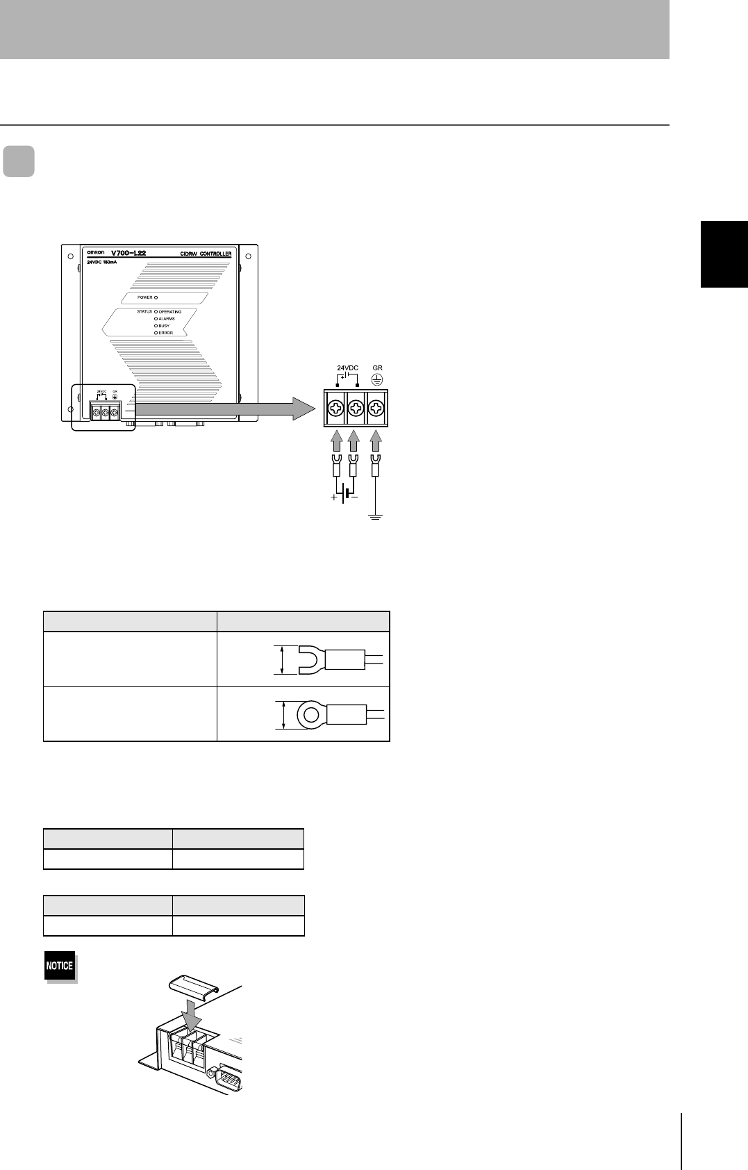
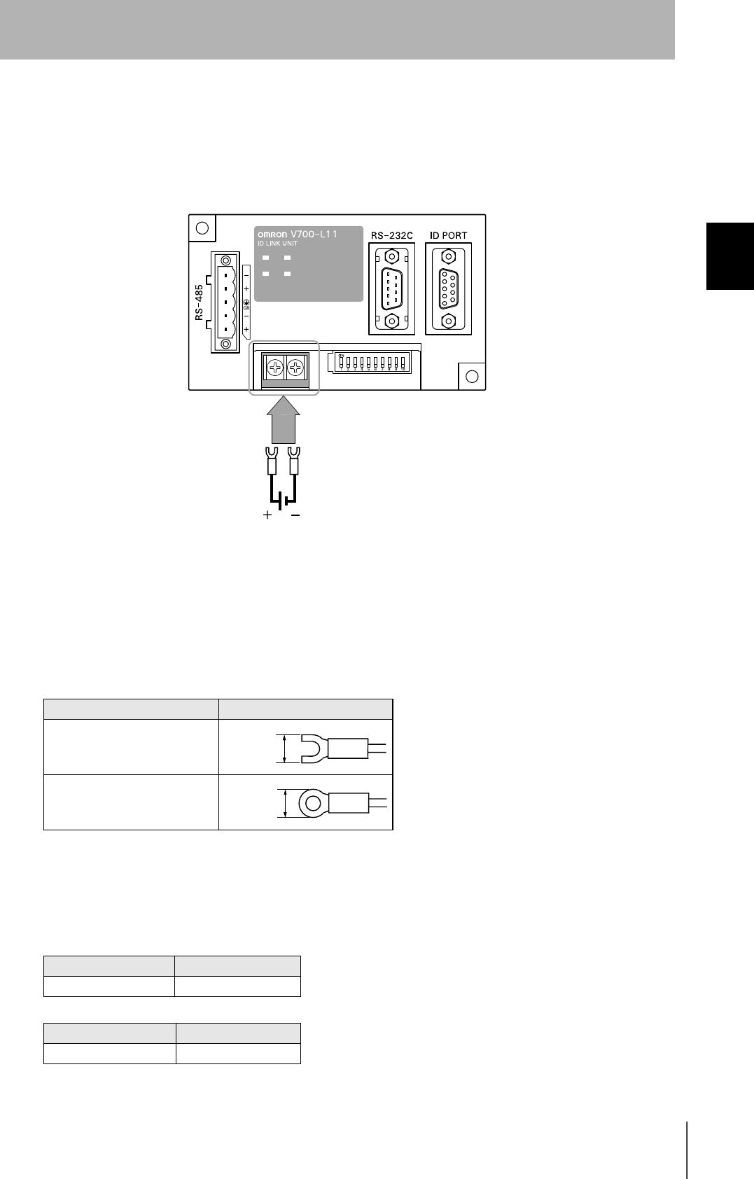
Power Supply and Grounding Wires
Connect the wires to the 24 VDC power supply terminals and frame ground terminal.
• Crimp terminals
The terminal screws on the terminal block are M3 size. Use appropriate crimp terminals for M3 screws
as shown below.
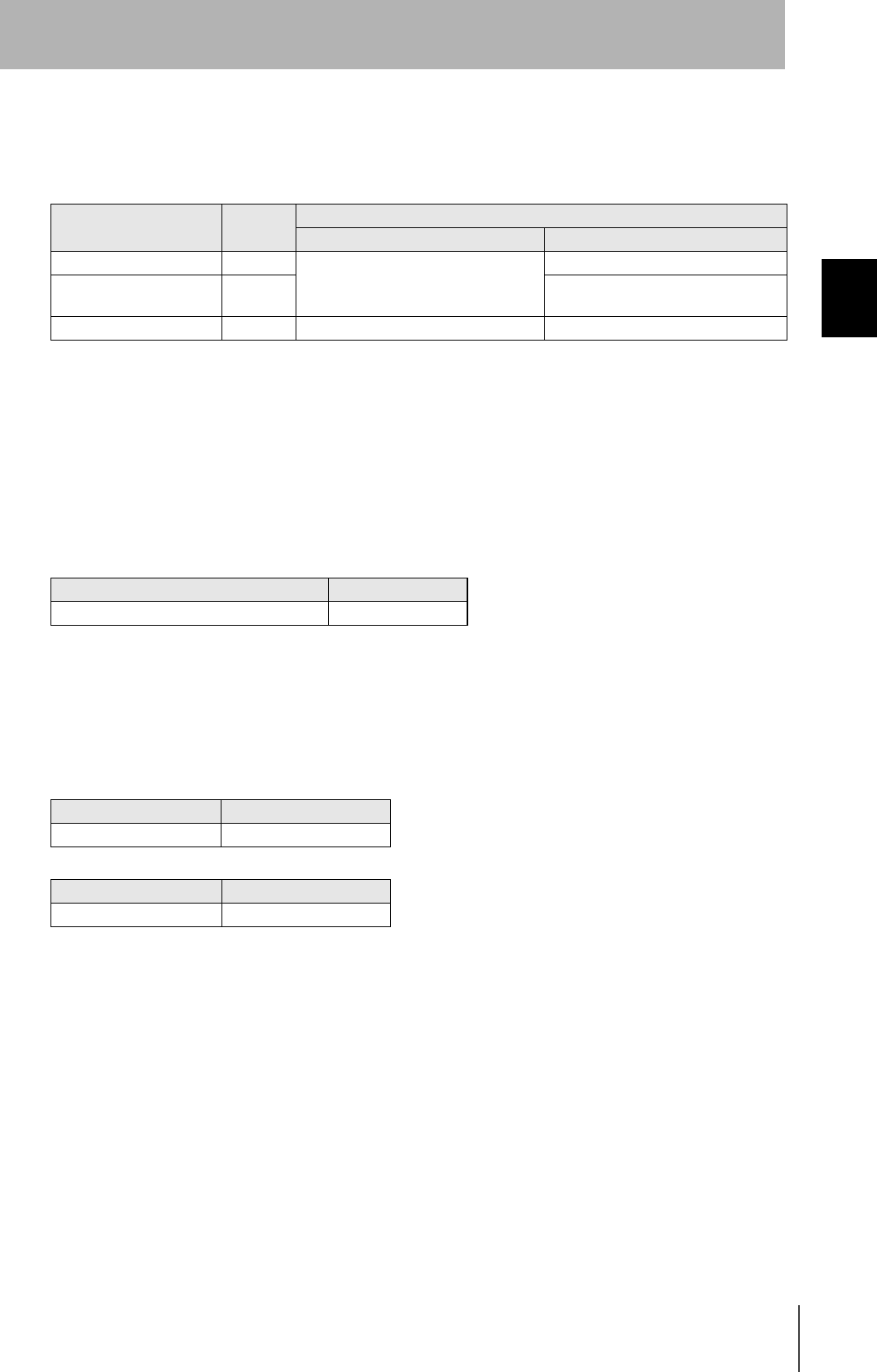
• Power supply
Use a power supply unit that satisfies the following conditions.
Be sure to replace the cover after wiring.
Crimp terminals
Shape Size
Forked
Round
Condition
Power supply voltage Output current
24 VDC +10%, -15% 500 mA DC min.
Recommended model
Manufacturer Model
OMRON S82K-01524
Ground to 100 Ω or less.
24 VDC
6 mm max.
6 mm max.
32
SECTION 2
Connections and Wiring
CIDRW System
User’s Manual
SECTION 2
Installation and Connections/Wiring
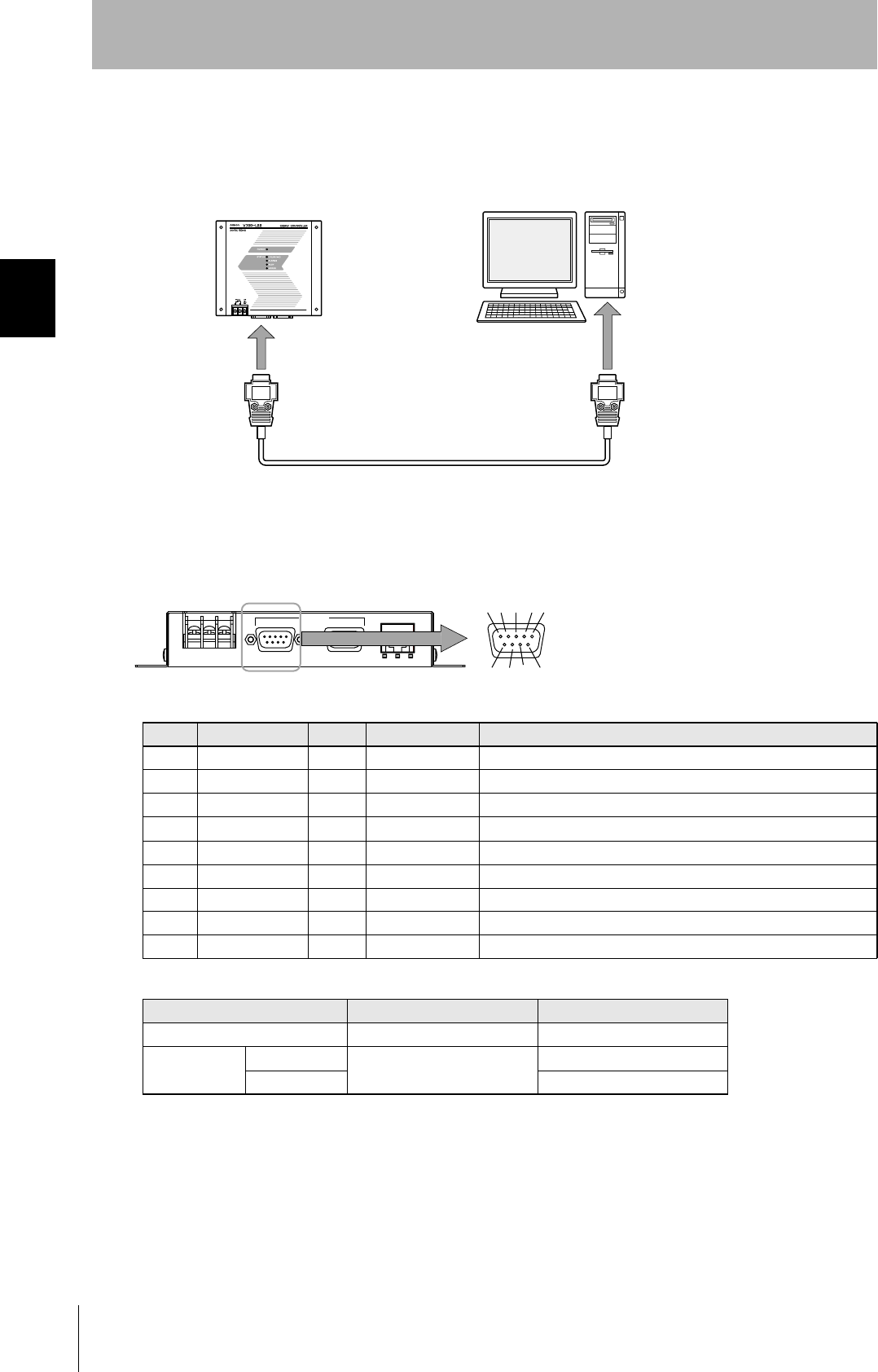
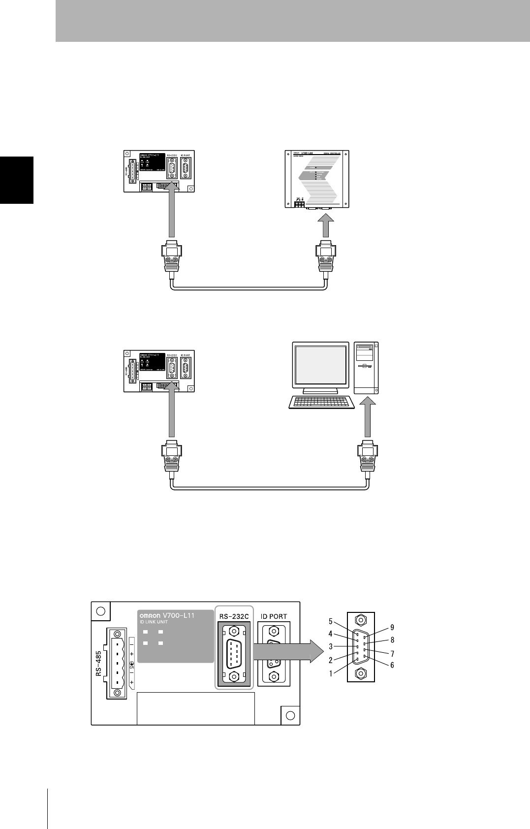
SECS port
The method for wiring for communications with a host device via the SECS port is explained here.
• Connector
The SECS port on the Controller is a D-SUB 9-pin connector. The pin arrangement is shown below.
Recommended model
Pin No. Signal name Symbol Signal direction Remarks
1 — NC — Not connected
2 Receive data RD Input
3 Send data SD Output
4 — — Output Always OFF
5 Signal ground SG —
6 — — Input Use in the "open" status.
7 Request send RS Input Always ON during normal operation
8 — NC — Not connected
9 — NC — Not connected
Manufacturer Model
Cable Hitachi Cable CO-MA-VV-SB 5PX28AWG
Connector Socket OMRON XM2D-0901
Hood XM2S-0913
CIDRW Controller Host
To the RS-232 port
To the SECS port
45%
5'%5 +& /#+06'0#00%'
The connector rim has electrical continuity with the
GR (frame ground) in the 24 VDC power supply ter-
minals.
33
CIDRW System
User’s Manual
SECTION 2
Connections and Wiring
SECTION 2
Installation and Connections/Wiring
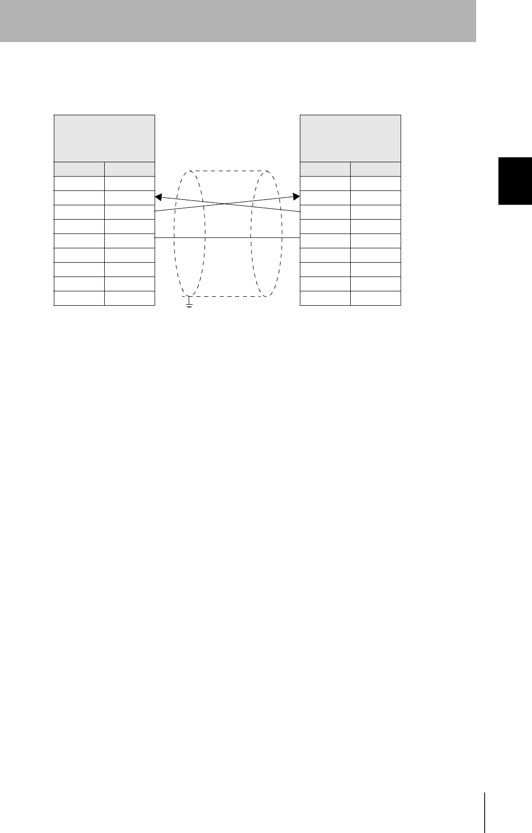
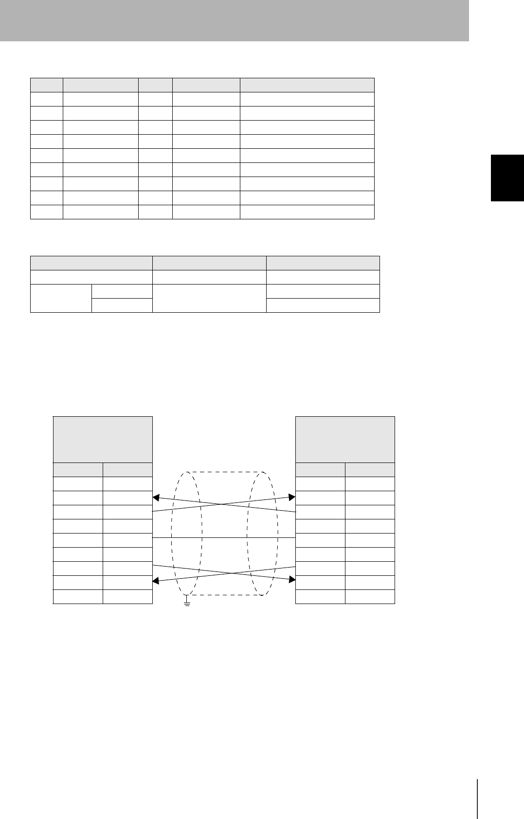
•Wiring
The cable length should be no greater than 15 m.
CIDRW Controller
V700-L22
D-SUB, 9-pin
Socket type #4-40
Name Pin No.
NC 1
RD 2
SD 3
NC 4
SG 5
NC 6
RS 7
NC 8
NC 9
PC/AT Computer
D-SUB, 9-pin
Socket type #4-40
Pin No. Name
1NC
2RD
3SD
4NC
5SG
6NC
7RS
8CS
9NC
Ground shielded wires either at the CIDRW Controller side or at the PC/AT side.
34
SECTION 2
Connections and Wiring
CIDRW System
User’s Manual
SECTION 2
Installation and Connections/Wiring
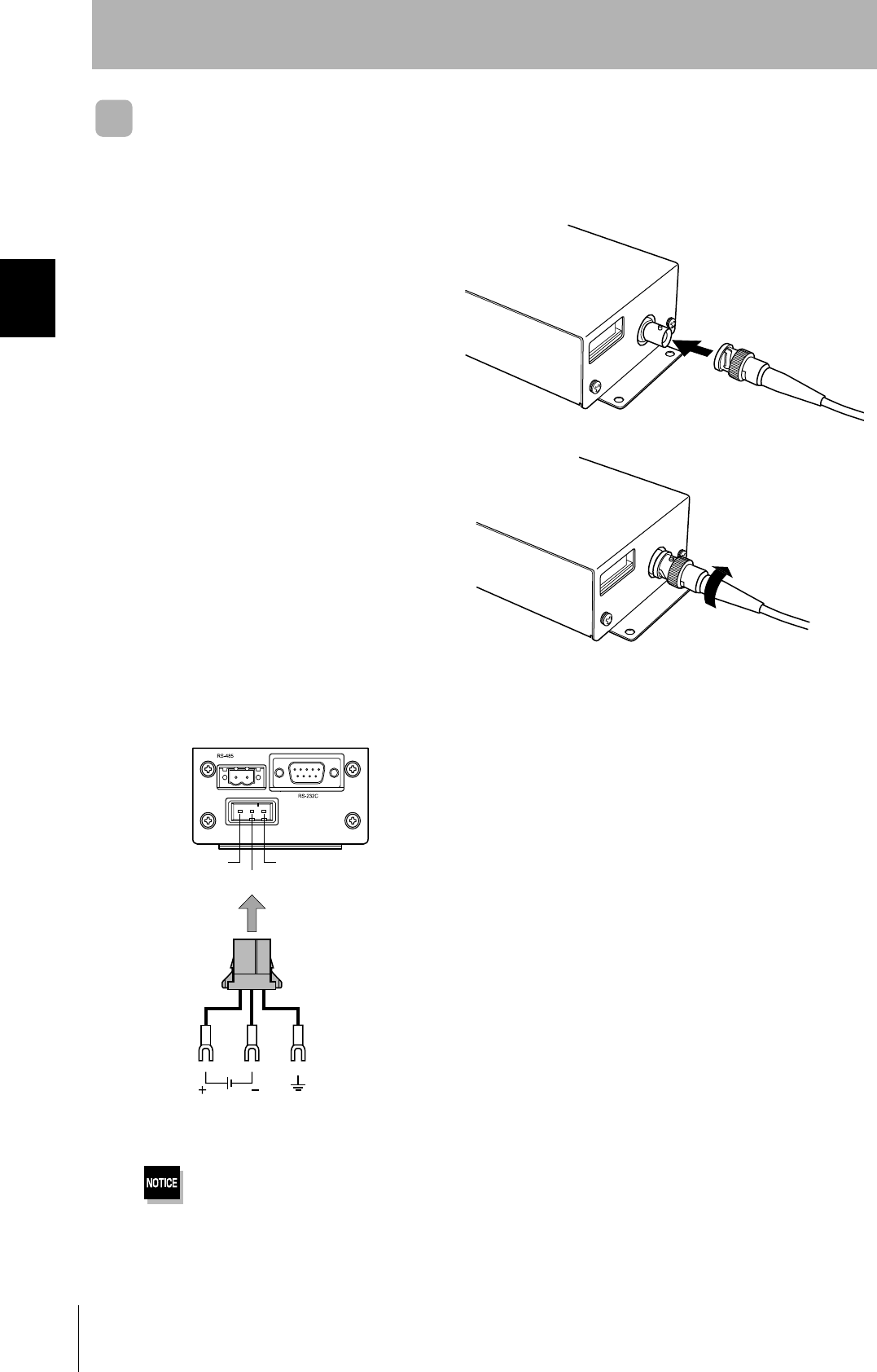
Amplifier Unit
Connector for connecting a CIDRW Head
1. Align the pin on the connector with the
channel in the cable connector and insert
the cable connector.
Hold the fixed part of the connector while making
this insertion.
2. After inserting the connector fully home,
turn the fixed part clockwise to lock it.
Power Supply and Grounding Wires
Connect the power supply and grounding wires to the dedicated power supply connector.
•The grounding wire should be connected to a ground exclusive to the Amplifier Unit. If the grounding wire is shared
with another unit, or connected to a beam in a building, there may be adverse effects.
•Make the grounding point as close as possible and the length of the grounding wire used as short as possible.
24 V+
24 V- GR
24 VDC Ground to 100 Ω or less
Connector
35
CIDRW System
User’s Manual
SECTION 2
Connections and Wiring
SECTION 2
Installation and Connections/Wiring
• Dedicated power supply connector and RS-485 port connector
Prepare a V640-A90 (can be purchased as an accessory).
• Dedicated power supply cable
Use an AWG20 - 24 cable.
Use a dedicated tool for crimping the cable to the connector pins.
• Power supply unit
Use a power supply unit that satisfies the following conditions.
Contents of the V640-A90 set (accessory)
Name Quantity When procured individually
Manufacturer Model
Power supply connector One Tyco Electronics 1-178288-3
Pins for power supply con-
nector
Three 175217-3
Connector for RS-485 port One Phoenix Contact MSTB2.5/2-STF-5.08
Recommended crimping tool
Manufacturer Model
Tyco Electronics 919601-1
Condition
Power supply voltage Output current
24 VDC +10%, -15% 300 mA DC min.
Recommended product
Manufacturer Model
OMRON S82K-01524
36
SECTION 2
Connections and Wiring
CIDRW System
User’s Manual
SECTION 2
Installation and Connections/Wiring
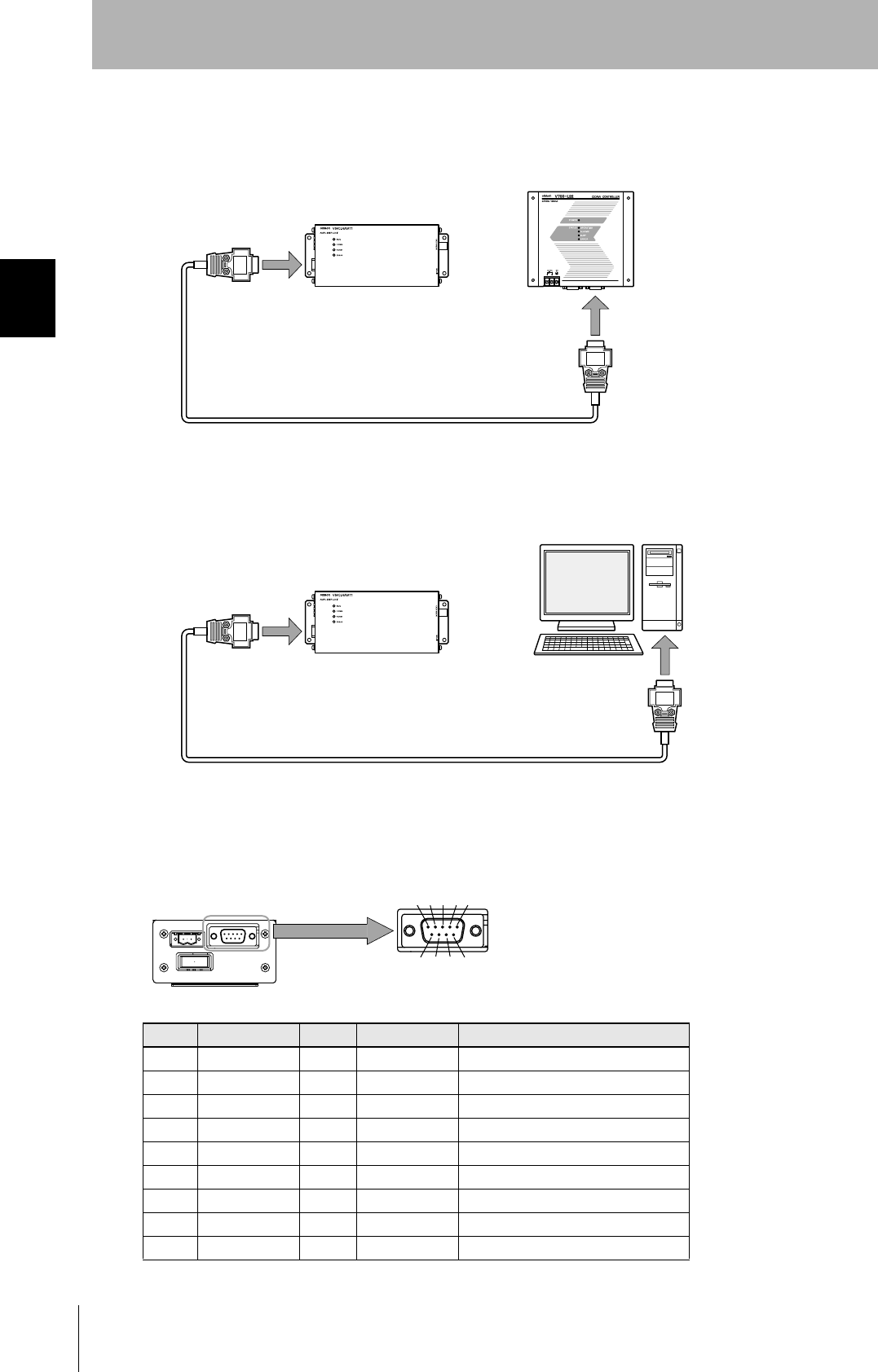
RS-232C Port
The method for connecting a CIDRW Controller or host device via the RS-232C port is explained here.
• Connector
The RS-232C port of the Amplifier Unit is a D-SUB, 9-pin connector. The pin arrangement is shown
below.
Pin No. Signal name Symbol Signal direction Remarks
1 — NC — Not connected
2 Receive data RD Input
3 Send data SD Output
4 — NC — Not connected
5 Signal ground SG —
6 — NC — Not connected
7 Request send RS Output Always ON during normal operation
8 Send enable CS Input
9 — NC — Not connected
Host
To ID port
To the RS-232C port
Amplifier Unit
To the RS-232C port
To the RS-232C port
CIDRW Controller
Amplifier Unit
The connector rim has electrical continuity with the GR (frame
ground) terminal in the dedicated power supply connector.
37
CIDRW System
User’s Manual
SECTION 2
Connections and Wiring
SECTION 2
Installation and Connections/Wiring
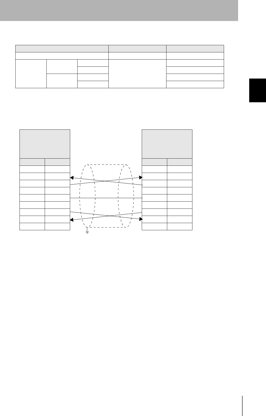
• Wiring for connection to a V700-L22 CIDRW Controller
The cable length should be no greater than 15 m.
Recommended model
Manufacturer Model
Cable Hitachi Cable CO-MA-VV-SB 5PX28AWG
Connector Host side Socket OMRON XM2D-0901
Hood XM2S-0913
Amplifier unit
side
Socket XM2D-0901
Hood XM2S-0911
Amplifier unit
V640-HAM11
D-SUB, 9-pin
Socket type
Metric screw, M2.6
Name Pin No.
NC 1
RD 2
SD 3
NC 4
SG 5
NC 6
RS 7
CS 8
NC 9
CIDRW Controller
V700-L22
D-SUB, 9-pin
Socket type
#4-40
Pin No. Name
1NC
2RD
3SD
4NC
5SG
6NC
7RS
8CS
9NC
Ground shielded wires either at the amplifier unit side or at the
CIDRW side.
38
SECTION 2
Connections and Wiring
CIDRW System
User’s Manual
SECTION 2
Installation and Connections/Wiring
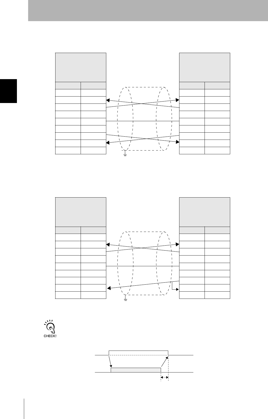
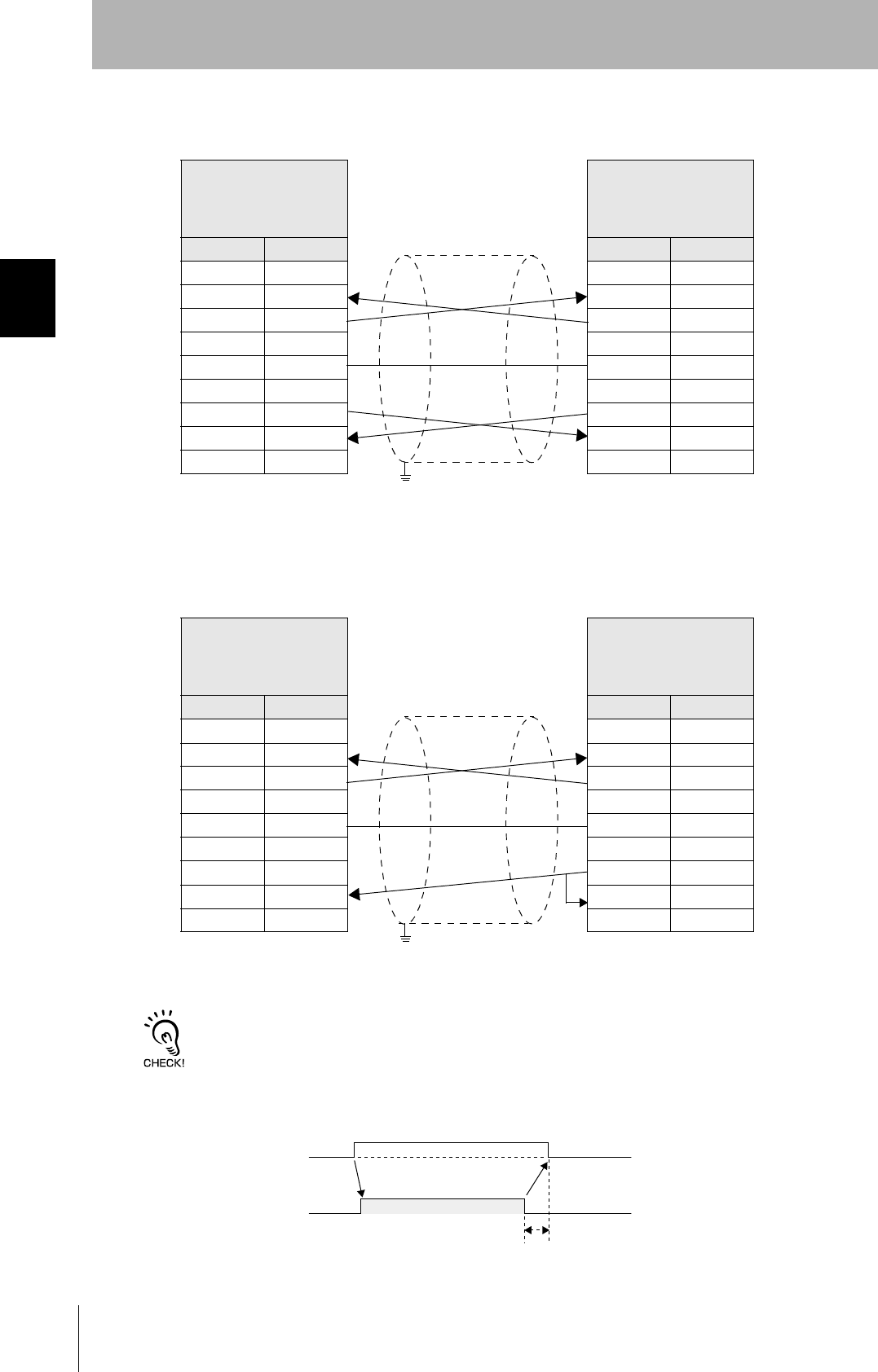
• Wiring for connection to a PC/AT computer (9-pin connector specification)
The cable length should be no greater than 15 m.
If the CS function is to be used at the PC/AT computer side, a return wire is required.
RS signal control method at the host device
In a 1:N connection using Link Units, the RS signals generated from the host device by normal control must be input as
CS signals. Turn the RS signals OFF within 15 ms after the completion of data transmission. Correct communications
will not be possible without this control.
Amplifier unit
V640-HAM11
D-SUB, 9-pin
Socket type
Metric screw, M2.6
Name Pin No.
NC 1
RD 2
SD 3
NC 4
SG 5
NC 6
RS 7
CS 8
NC 9
PC/AT Computer
D-SUB, 9-pin
Socket type
#4-40
Pin No. Name
1NC
2RD
3SD
4NC
5SG
6NC
7RS
8CS
9NC
Ground shielded wires either at the CIDRW Controller side or at the
PC/AT side.
Amplifier unit
V640-HAM11
D-SUB, 9-pin
Socket type
Metric screw, M2.6
Name Pin No.
NC 1
RD 2
SD 3
NC 4
SG 5
NC 6
RS 7
CS 8
NC 9
PC/AT computer
D-SUB, 9-pin
Socket type
#4-40
Pin No. Name
1NC
2RD
3SD
4NC
5SG
6NC
7RS
8CS
9NC
Ground shielded wires either at the CIDRW Controller side or at the
PC/AT side.
SD at host device
RS at host device
ON only during data transmission from the host device
Within 15 ms
39
CIDRW System
User’s Manual
SECTION 2
Connections and Wiring
SECTION 2
Installation and Connections/Wiring
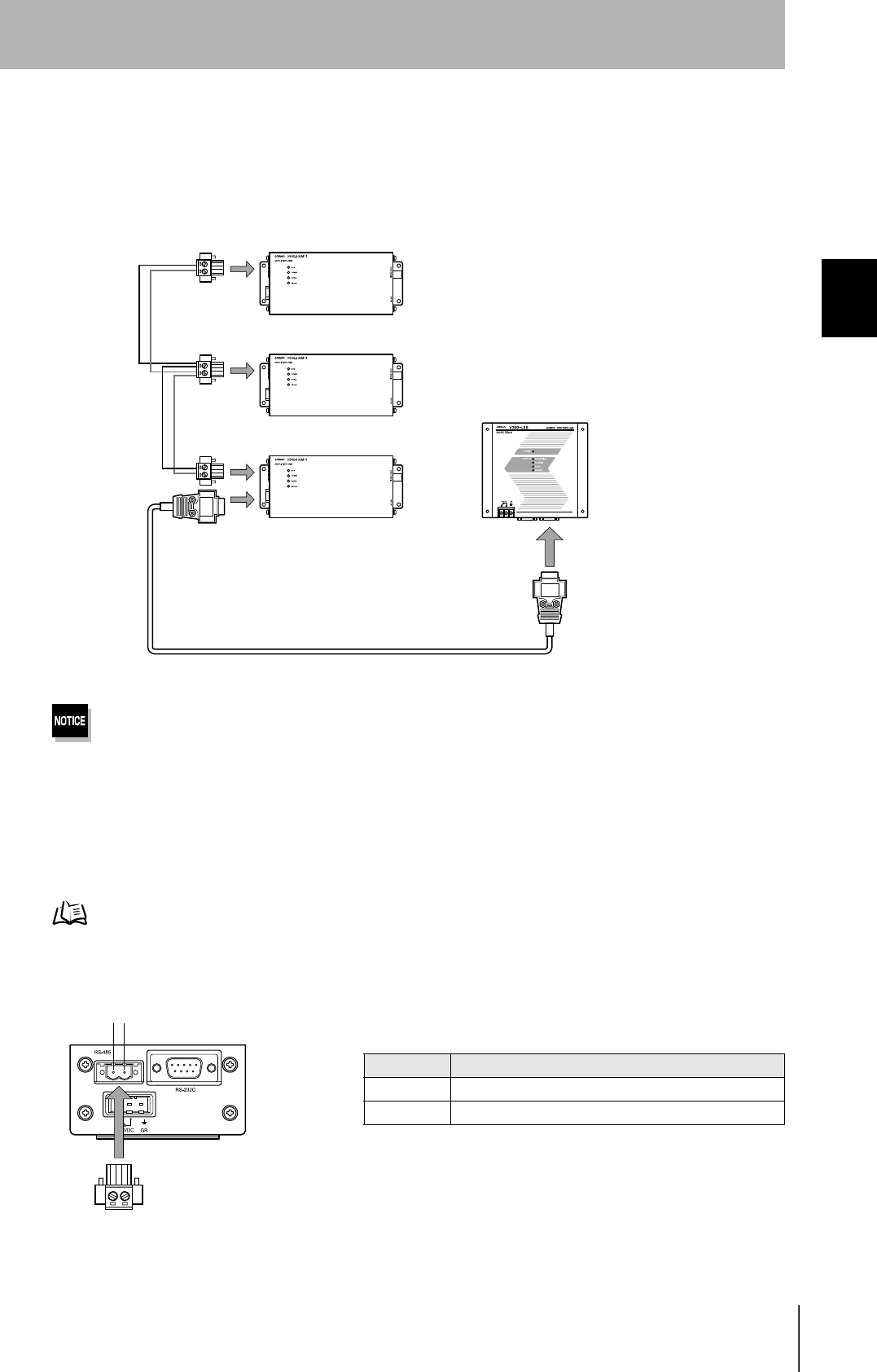
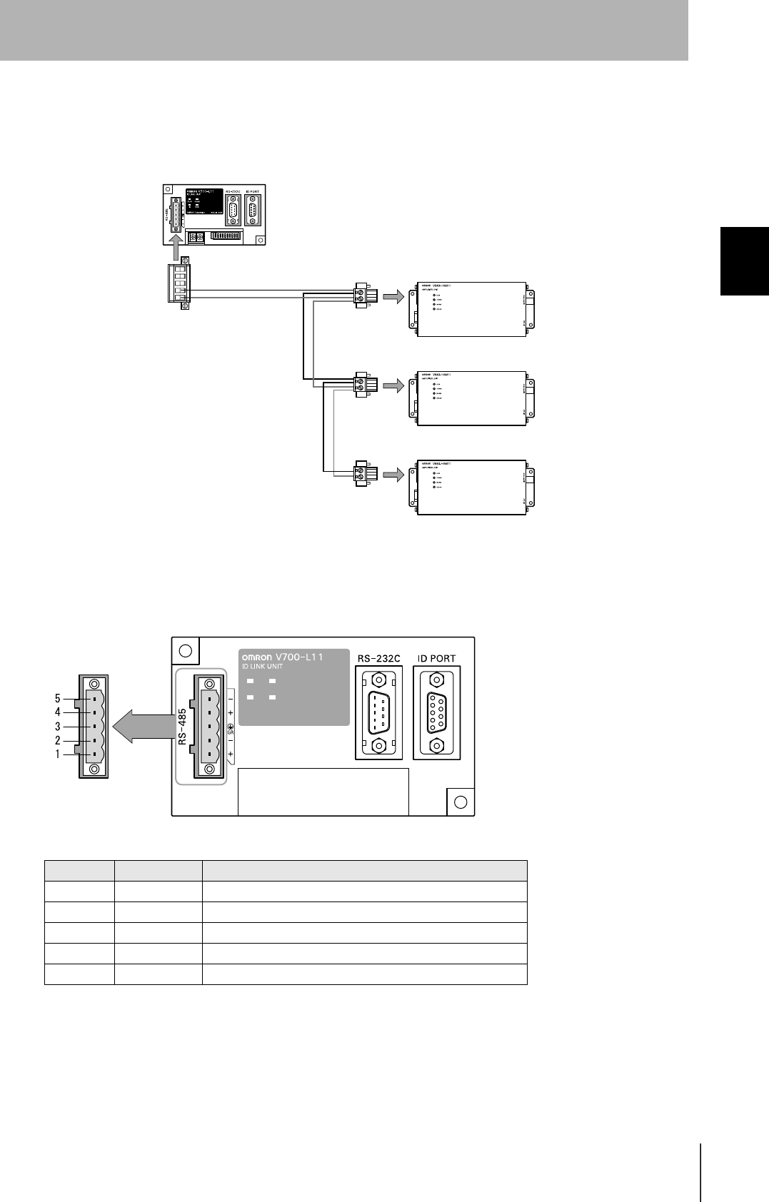
RS-485 Port
The method for connection to the RS-485 port of another Amplifier Unit when multiple CIDRW Heads
are used is explained here.
The maximum total length of RS-485 cable is 50 m.
• Connector
Prepare a V640-A90 (can be purchased as an accessory) as the connector for the RS-485 port on the
Amplifier Unit.
Refer to page 35.
The pin arrangement is shown below.
To the RS-485 port Amplifier Unit
To the RS-232C port
CIDRW Controller
Connector
Name Function
- Connect to the "minus" line of another Amplifier Unit.
+ Connect to the "plus" line of another Amplifier Unit.
-
40
SECTION 2
Connections and Wiring
CIDRW System
User’s Manual
SECTION 2
Installation and Connections/Wiring
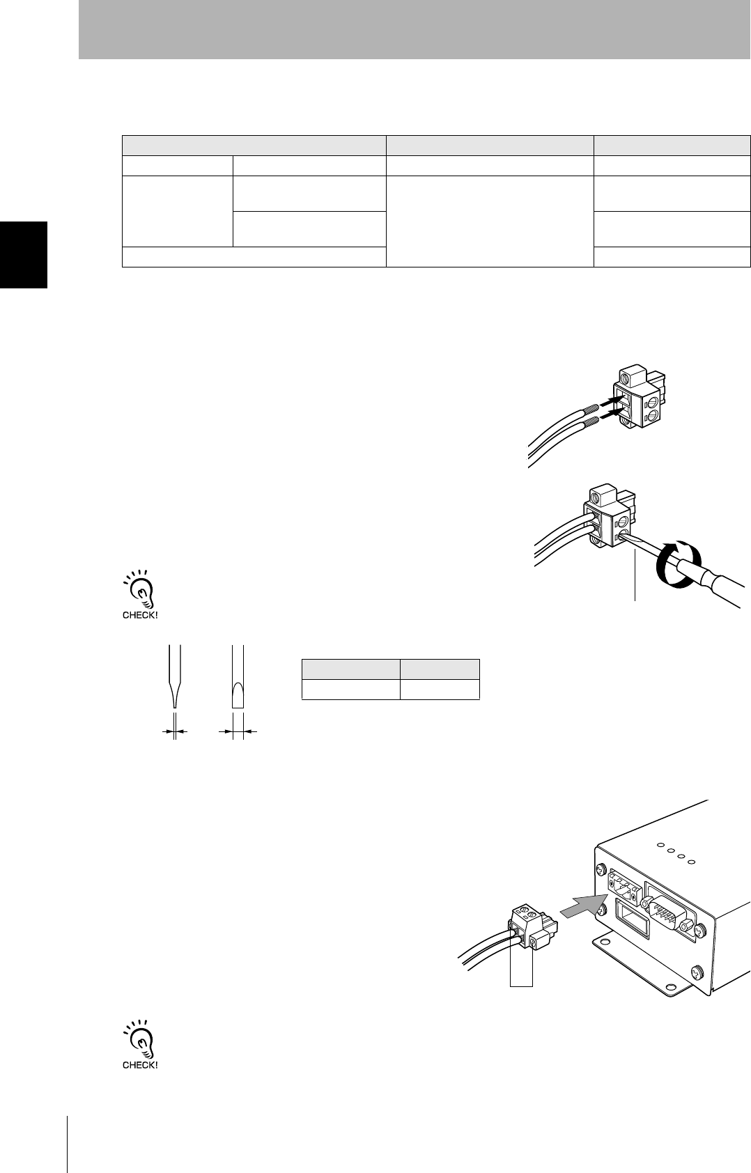
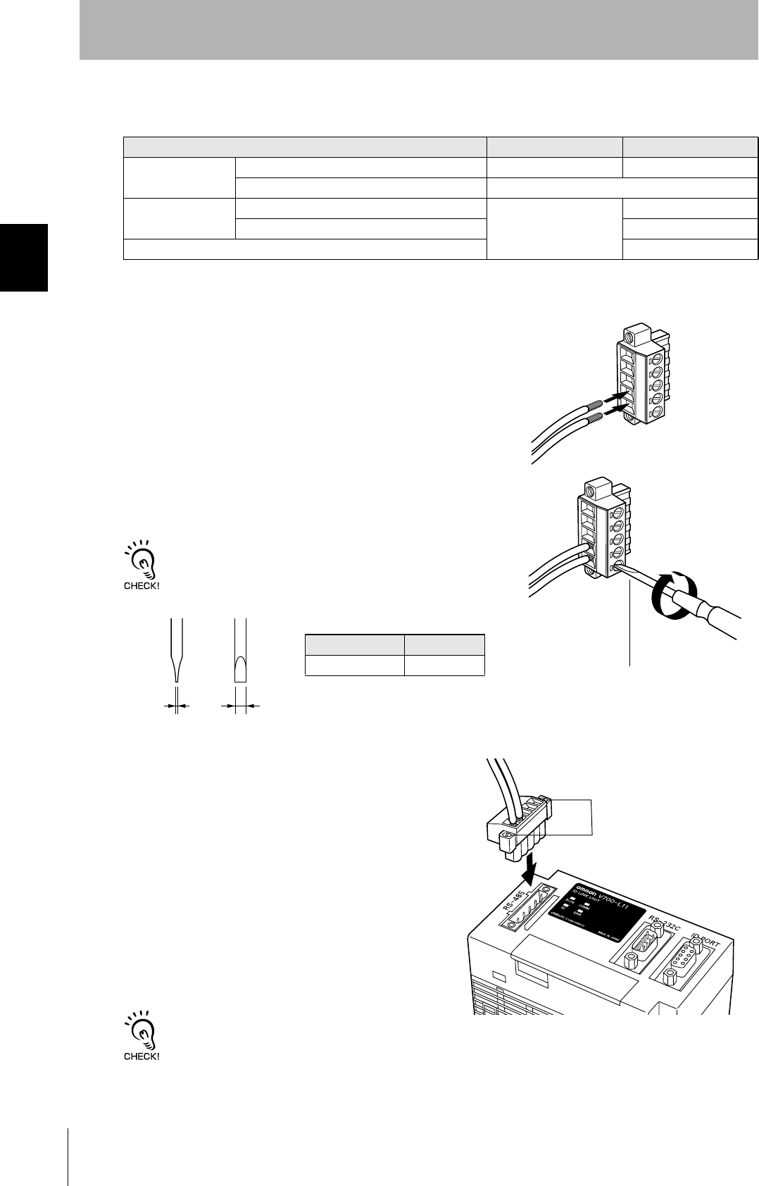
• Notes on cables
•Wiring method
1. Attach crimp terminals to stripped portions of the cables.
2. Insert the wires into the correct holes in the connector, bearing
the orientation of the connector in mind.
3. Tighten the set screws of the connector firmly to secure the
cables.
The appropriate tightening torque is around 0.5 N·m.
A standard, tapered screwdriver will not enter all the way into the
screw holes. Use a small gauge flat-blade screwdriver whose shaft
and tip have the same thickness.
4. Having fitted the connector to the cable, connect it
to an Amplifier Unit.
Orient the cable connector correctly in relation to the connector
on the Amplifier Unit, and fasten the cable connector by fully
tightening the retaining screws.
Disconnecting the connector
Fully loosen the two screws, then grip the projections on the connector and pull it straight out. If it is difficult to pull the
connector out, press down on the Amplifier Unit while pulling on the connector.
Recommended model
Manufacturer Model
Cable RS-485 signal wire Tachii Electric Wire MVVS 2CX0.5SQ
Crimp terminals When one wire is connected
to each terminal.
Phoenix Contact AI0.5-8WH
When two wires are con-
nected to each terminal.
AI-TWIN2×0.5-8WH
Crimping tool CRIMPFOX UD6
Small flat-blade screw-
driver with no taper
Recommended screwdriver
Manufacturer Model
OMRON XW4Z-00C
Side view Face view
0.6 mm 3.5 mm
Set screws
41
CIDRW System
User’s Manual
SECTION 2
Connections and Wiring
SECTION 2
Installation and Connections/Wiring
Link Unit
Power Supply
Opening the cover on the top face of the Link Unit exposes the power supply terminals.
• Crimp terminals
The terminal screws on the terminal block are M3 size. Use appropriate crimp terminals for M3 screws
as shown below.
• Power supply
Use a power supply unit that satisfies the following conditions.
Crimp terminals
Shape Size
Forked
Round
Condition
Power supply voltage Output current
24 VDC +10%, -15% 500 mA DC min.
Recommended model
Manufacturer Model
OMRON S82K-01524
24 VDC
6 mm max.
6 mm max.
42
SECTION 2
Connections and Wiring
CIDRW System
User’s Manual
SECTION 2
Installation and Connections/Wiring
Host Connection Port
The method for connecting to a CIDRW Controller or host device via the RS-232C port is explained
here.
• Connector
The host device connection port on the Link Unit is a D-SUB, 9-pin connector. The pin arrangement is
shown below.
CIDRW Controller
Link Unit
To ID port
To the RS-232C port
To host device port
Link Unit
To host device port
Host
The connector rim does not have electrical
continuity with the GR (frame ground) termi-
nal in the multi-connection port.
43
CIDRW System
User’s Manual
SECTION 2
Connections and Wiring
SECTION 2
Installation and Connections/Wiring
• Wiring for connection to a CIDRW Controller
The cable length should be no greater than 15 m.
Pin No. Signal name Symbol Signal direction Remarks
1 — NC — Not connected
2 Receive data RD Input
3 Send data SD Output
4 — NC — Not connected
5 Signal ground SG —
6 — NC — Not connected
7 Request send RS Output Always ON during normal operation
8 Send enabled CS Input
9 — NC — Not connected
Recommended model
Manufacturer Model
Cable Hitachi Cable CO-MA-VV-SB 5PX28AWG
Connector Socket OMRON XM2D-0901
Hood XM2S-0913
Link unit
V700-L11
D-SUB, 9-pin, female
Socket type #4-40
Name Pin No.
NC 1
RD 2
SD 3
NC 4
SG 5
NC 6
RS 7
CS 8
NC 9
CIDRW Controller
V700-L22
D-SUB, 9-pin, female
Socket type #4-40
Pin No. Name
1NC
2RD
3SD
4NC
5SG
6NC
7RS
8CS
9NC
Ground shielded wires at the CIDRW Controller side.
44
SECTION 2
Connections and Wiring
CIDRW System
User’s Manual
SECTION 2
Installation and Connections/Wiring
• Wiring for connection to a PC/AT computer
If the CS function is to be used at the PC/AT computer side, a return wire is required.
RS signal control method at the host device
In a 1:N system using Link Units, the RS signals generated from the host device by normal control must be input as CS
signals. Turn the RS signals OFF within 15 ms after the completion of data transmission. Correct communications will
not be possible without this control.
Link unit
V700-L11
D-SUB, 9-pin
Socket type #4-40
Name Pin No.
NC 1
RD 2
SD 3
NC 4
SG 5
NC 6
RS 7
CS 8
NC 9
PC/AT Computer
D-SUB, 9-pin
Socket type #4-40
Pin No. Name
1NC
2RD
3SD
4NC
5SG
6NC
7RS
8CS
9NC
Ground shielded wires at the PC/AT computer side.
Link unit
V700-L11
D-SUB, 9-pin
Socket type #4-40
Name Pin No.
NC 1
RD 2
SD 3
NC 4
SG 5
NC 6
RS 7
CS 8
NC 9
PC/AT Computer
D-SUB, 9-pin
Socket type #4-40
Pin No. Name
1NC
2RD
3SD
4NC
5SG
6NC
7RS
8CS
9NC
Ground shielded wires at the PC/AT computer side.
SD at host device
RS at host device
ON only during data transmission from the host device
Within 15 ms
45
CIDRW System
User’s Manual
SECTION 2
Connections and Wiring
SECTION 2
Installation and Connections/Wiring
Multi-connection port
The method for connecting to an Amplifier Unit is explained here.
• Connector
Pin No. Name Function
5 - No wiring is required. (Short with terminal 2 within the circuit)
4 + No wiring is required. (Short with terminal 1 within the circuit)
3 GR Ground to 100 Ω or less.
2 - Connect to the "minus" line of the Amplifier Unit.
1 + Connect to the "plus" line of the Amplifier Unit.
Link Unit
Amplifier Unit
To the RS-485 port
To multi-connection port
46
SECTION 2
Connections and Wiring
CIDRW System
User’s Manual
SECTION 2
Installation and Connections/Wiring
•Cable
•Wiring method
1. Attach crimp terminals to stripped portions of the cables.
2. Insert the wires into the correct holes in the connector, bearing
the orientation of the connector in mind.
3. Tighten the set screws of the connector firmly to secure the
cables.
The appropriate tightening torque is around 0.5 N·m.
A standard, tapered screwdriver will not enter all the way into the
screw holes. Use a small gauge flat-blade screwdriver whose shaft
and tip have the same thickness.
4. Having fitted the connector to the cable, connect
it to the Link Unit.
Orient the cable connector correctly in relation to the connec-
tor on the Link Unit, and fasten the cable connector by fully
tightening the retaining screws.
Disconnecting the connector
Fully loosen the two screws, then grip the projections on the connector and pull it straight out. If it is difficult to pull the
connector out, press down on the Link Unit while pulling on the connector.
Recommended Product
Manufacturer Model
Cable RS-485 signal wire Tachii Electric Wire MVVS 2CX0.5SQ
Frame ground line AWG22 - 20 cable
Crimp terminals When one wire is connected to each terminal. Phoenix Contact AI0.5-8WH
When two wires are connected to each terminal. AI-TWIN2×0.5-8WH
Crimping tool CRIMPFOX UD6
Small gauge flat-blade
screwdriver with no taper
Recommended screwdriver
Manufacturer Model
OMRON XW4Z-00C
Side view Face view
0.6 mm 3.5 mm
Set screws

48
SECTION 3
Set the Communications Conditions for the CIDRW Controller
CIDRW System
User’s Manual
SECTION 3
Preparing for Communications
Set the Communications Conditions for the CIDRW
Controller
Set the communications conditions of the CIDRW Controller only when SECS is used.
Switch to the Setting mode
The CIDRW Controller has two operating modes, the "Normal Operation mode" and the "Setting
mode."
Switch to the "Setting mode" to set the communications conditions.
There are two methods for switching the mode. Use the one that is appropriate for the circumstances.
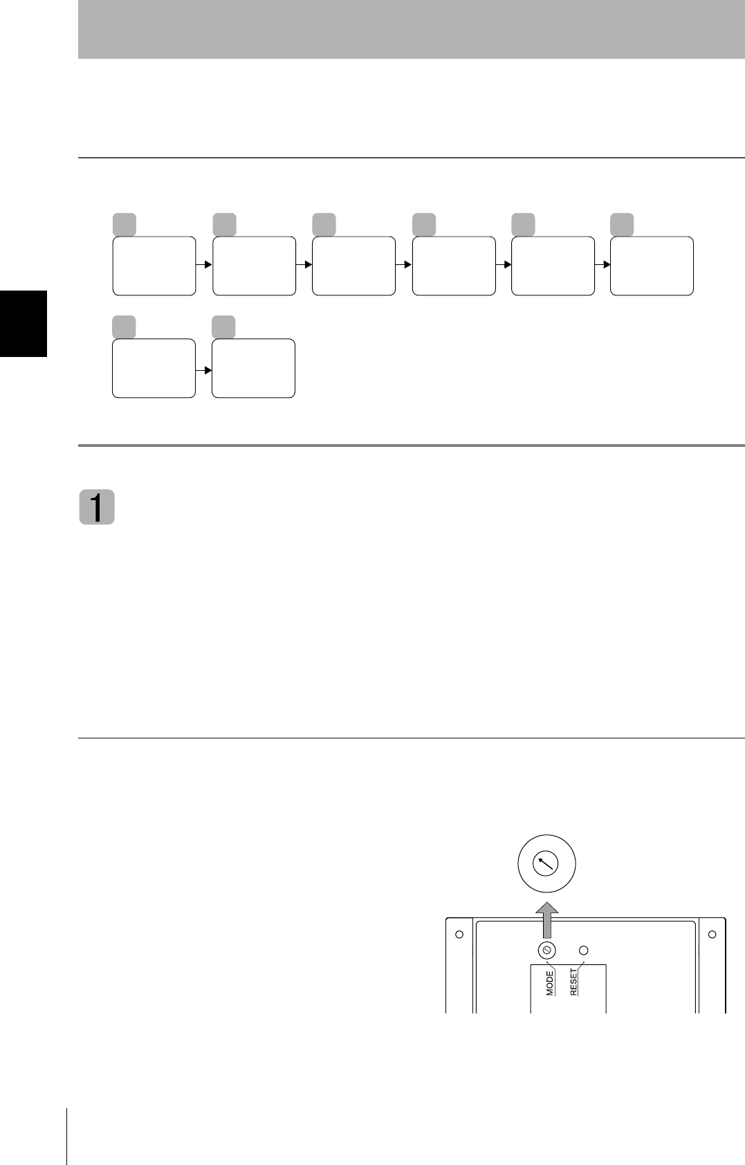
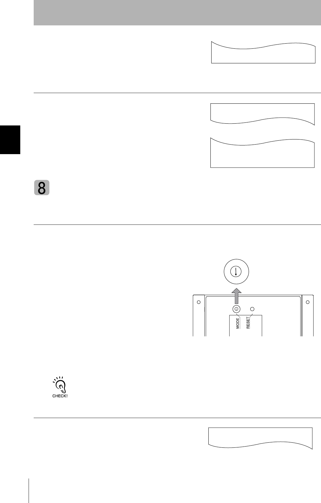
Changing the Position of the Mode Switch on the Bottom of the Unit
This is the convenient method for setting before mounting the unit.
1. Turn OFF the power to the CIDRW Controller.
2. Set the mode switch on the bottom of the unit to
"3."
1
Switch to the
Setting mode.
2
Start the
terminal
software.
3
Set the
parameters for the
communications
conditions.
4
Change the
Carrier ID
5
Change the
Data
segment
area.
6
Change the
response
time-out time.
7
Set Software
Revisions
8
Return to the
Normal
Operation
mode.
2
1
0
7
6
5
7
3
2
1
0
7
6
5
7
3
49
CIDRW System
User’s Manual
SECTION 3
Set the Communications Conditions for the CIDRW Controller
SECTION 3
Preparing for Communications
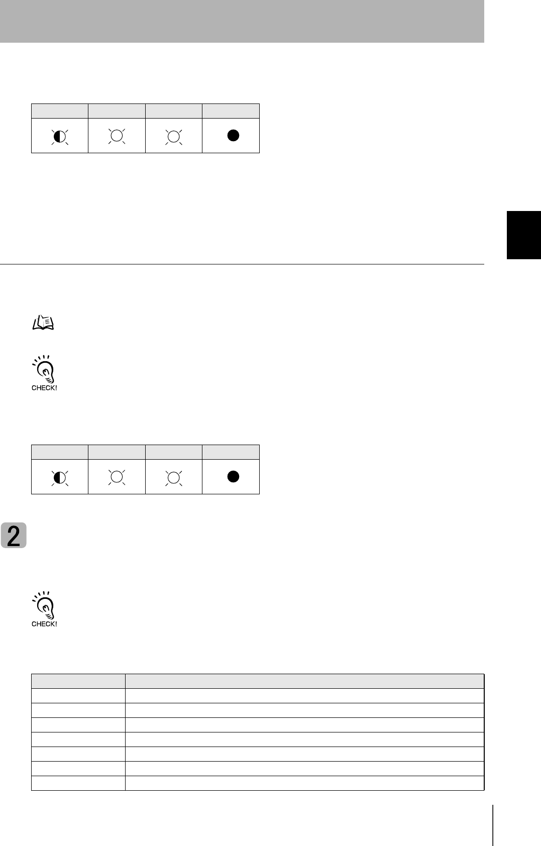
3. When all of the devices to be used are connected, turn the power ON.
The system starts up in the Setting mode, and the indicators react as shown below.
Sending a Switching Command from the Host Device
This method is convenient when the unit has already been mounted and the switch on the bottom can-
not be repositioned to "3."
During operation in the Normal Operation mode, a command is sent from the host device to switch to
the Setting mode.
1. Send a subsystem command (S18F13 ChangeState CPVAL1 = "PS") from the host device.
Refer to page page 77.
CPVAL1="PS" is an expansion designation unique to V700-L22 and does not conform to SEMI standards.
The system is automatically restarted and the mode switches to the Setting mode.
The operation indicators react as shown below.
Start the terminal software
Use the host device's terminal software for the setting.
The commands and communications conditions in the setting mode are unique to OMRON. They do not conform to the
SEMI standards. For the terminal software, use Hyper Terminal, which is standard with Windows, or a similar program.
The communications conditions for communication between the host device and CIDRW Controller
are fixed. Make the following settings using the terminal software.
OPERATING ALARMS BUSY ERROR
OPERATING ALARMS BUSY ERROR
Item Setting
Baud rate 9600 bps
Data length 8 bits
Parity EVEN
Stop bit 1
Communications control None
Send code At the end of a line (when [ENTER] is input), the "line feed" characters ([LF]) are appended.
Display Local echo
50
SECTION 3
Set the Communications Conditions for the CIDRW Controller
CIDRW System
User’s Manual
SECTION 3
Preparing for Communications
Set the parameters for the communications conditions
Specify the parameters whose settings are to be changed from the terminal software of the host
device. The commands, and the parameters that can be set are indicated below.
The setting mode commands do not conform to SEMI standards.
For the terminal software, use Hyper Terminal, which is standard with Windows, or a similar program.
List of Commands
Designation Command Input Explanation
Parameter designation (Tag name) = (Set value) <CRLF> Specify the parameter value corresponding to the tag name.
Parameter confirmation ::END Checks the parameter designations that have been received so
far and, if there is no error, confirms the settings.
Comment # (Comment) <CRLF>
or
CRLF
This is ignored as the comment line.
Tag Name List
Classification Parameter Tag name Setting range
Default
setting
Protocol Baud Rate S_BAUD 1200, 2400, 4800, 9600, 19200, 38400, 57600,
115200 bps
9600 bps
Device ID S_DEVID 0 to 32767 0
Time-out between characters S_T1 0.1 to 10 s 0.5 s
Protocol time-out S_T2 0.2 to 25 s 10 s
Response time-out S_T3 1 to 120 s 45 s
Time-out between blocks S_T4 1 to 120 s 45 s
Retry limit S_RTY 0 to 31 3
Master/slave S_MS M : Master
S : Slave
M
SECS Double block detection yes/no S_DB 1: The header of the block currently being
received is compared with the correct block
received immediately before, and double
blocks are detected.
0: Double block detection is not performed.
1
Source ID S_SRC 0 to 32767 0
Single block No. S_BNO 0, 1 1
Operation Baud rate for communications
with Amplifier Unit/Link Unit
C_BAUD 9600, 19200, 38400 bps
Use a consistent baud rate setting within the
same system configuration.
9600 bps
Number of heads count pro-
cessing
C_HEAD 0 to 31
0: The number of heads is automatically
detected at the start. Any increase or
decrease in the number of heads is auto-
matically detected.
1 to 31: The number of heads is specified. The
number of heads detected is compared
with this specified number of heads. If
the number of heads changes, for exam-
ple because a head fails, an error (with
alarm) is detected.
If a head is not connected or an error is
detected with a connected head, so that
the number of heads does not match the
specified number, an error (with alarm) is
detected.
0
51
CIDRW System
User’s Manual
SECTION 3
Set the Communications Conditions for the CIDRW Controller
SECTION 3
Preparing for Communications
1. Specify the parameters to be changed.
When the first parameter is specified, the ALARMS indicator flashes.
2. Confirm the parameter change.
The input parameter is checked and written.
When writing is completed, a message indicating the result is displayed.
The ALARMS indicator lights.
If writing is completed with an error, the parameters are not updated.
The figure in square brackets [ ] indicates the line number where the
error was first detected. If a parity error is detected in the received char-
acters, this figure is [0].
Check the sent data based on this information.
A text file is created based on the data that is keyed in, as shown below, and this data can be conveniently transmitted
using the terminal's text file send function.
S_BAUD=19200
S_DEVID=1
S_BNO=0
_
::END
_
SETUP_COMPLETE
_
SETUP_FAILED [2]_
When writing is completed without error
When writing is completed with an error
#Parameter Setting File for SystemA
#Protocol
S_BAUD=19200
S_DEVID=1
#SECS
S_BNO=0
::END
Example: PRM.TXT
52
SECTION 3
Set the Communications Conditions for the CIDRW Controller
CIDRW System
User’s Manual
SECTION 3
Preparing for Communications
!Check for Correct Setting
The currently set data can be output so that you can check if it is correct.
1. Send the parameter output command "::GET_PARAM"
from the host device.
The current communication parameter settings are displayed.
Change the Carrier ID
To read the carrier ID, the CID has to be specified within the area where the carrier ID can be set
(CarrierIDField) within the ID tag's memory. This section explains the procedure for setting the "carrier
ID offset" (attribute name: CarrierIDOffset) and the "carrier ID size (bytes)" (attribute name:
CarrierIDLength) in the memory map of the ID tag.
The commands, and the parameters that can be set, are indicated below.
• Settings that exceed the carrier ID area (*) cannot be made. If such a setting is made, an
error occurs.
*: (CIDOF+CIDLN) ≤ T_CIDLEN
• "Carrier ID offset" and "carrier ID size (bytes)" can only be changed in the L22 mode. They
cannot be changed in the L21 mode. When you change from the L22 mode to the L21 mode,
"carrier ID offset" and "carrier ID size (bytes)" are returned to their initial settings.
List of Commands
Designation Command input Explanation
Parameter designation (Tag name) = (Set value) <CRLF> Specify the parameter value corresponding to the tag name.
Parameter confirmation ::END Checks the parameter designations that have been received so
far and, if there is no error, confirms the settings.
Comment # (Comment) <CRLF>
or
CRLF
This is ignored as the comment line.
Tag Name List
Parameter Tag name Setting range Default setting
Carrier ID offset CIDOF 0 -15 0
Carrier ID size (bytes) CIDLN 01 - 16 16
::GET_PARAM
S_BAUD=19200
S_DEVID=1
S_T1=0.5
S_T2=10.0
S_T3=45
S_T4=3
S_RTY=3
S_MS=M
S_SRC=0
S_BNO=0
C_BAUD=9600
C_HEAD=0
::END
_
53
CIDRW System
User’s Manual
SECTION 3
Set the Communications Conditions for the CIDRW Controller
SECTION 3
Preparing for Communications
1. Specify the parameters to be changed.
When the first parameter is specified, the ALARMS indicator flashes.
2. Confirm the parameter change.
The input parameter is checked and written.
Check for Correct Setting
The currently set data can be output so that you can check if it is correct.
1. Send the parameter output command "::GET_E99SYS"
from the host device.
The carrier ID settings are displayed.
Do not change operation parameters other than RT, CIDOF, and CIDLN.
This can cause the system to stop operating correctly.
Change the data segment area
The data segment area (memory map) must be changed to communicate with ID Tags (RI-TRP-DR2B,
made by Texas Instruments). The procedure for changing the data segment area is explained here.
Data Segment Area Refer to page 122.
The commands, and the parameters that can be set, are indicated below.
List of Commands
Designation Command input Explanation
Parameter designation (Tag name) = (Set value) <CRLF> Specify the parameter value corresponding to the tag name.
Parameter confirmation ::END Checks the parameter designations that have been received so
far and, if there is no error, confirms the settings.
Comment # (Comment) <CRLF>
or
CRLF
This is ignored as the comment line.
CIDOF=0
CIDLN=16
::END
_
::GET_E99SYS
RT=10.0
CT=0.1
RTY=3
DINST=
MENT=
MODEL=L22
HREV=001.04
CIDOF=00
CIDLN=16
::END
_

54
SECTION 3
Set the Communications Conditions for the CIDRW Controller
CIDRW System
User’s Manual
SECTION 3
Preparing for Communications
1. The form of the input from the host device is shown in the
figure to the right.
When the first parameter is specified, the ALARMS indicator flashes.
2. Confirm the parameter change.
The input parameter is checked and written.
When writing is completed, a message indicating the result is displayed.
The ALARMS indicator lights.
If writing is completed with an error, the parameters are not updated.
The figure in square brackets [ ] indicates the line number where the
error was first detected. If a parity error is detected in the received char-
acters, this figure is [0].
Check the sent data based on this information.
Tag Name List
Parameter Tag name Setting range Default setting
Number of bytes in the carrier ID T_CIDLEN 16 (fixed)
The setting must maintain the following relationship
(CIDOF + CIDLN) ≤ T_CIDLEN
16
Segment name T_SEGN "S01" to "S99" "S01" to "S28"
Number of bytes in a segment T_SEGL 8 (fixed) 8
T_CIDLEN=16
T_SEGN=S01
T_SEGL=8
T_SEGN=S02
T_SEGL=8
T_SEGN=S03
T_SEGL=8
T_SEGN=S04
T_SEGL=8
T_SEGN=S05
T_SEGL=8
T_SEGN=S06
T_SEGL=8
T_SEGN=S07
T_SEGL=8
T_SEGN=S08
T_SEGL=8
T_SEGN=S09
T_SEGL=8
T_SEGN=S10
T_SEGL=8
T_SEGN=S11
T_SEGL=8
T_SEGN=S12
T_SEGL=8
T_SEGN=S13
T_SEGL=8
T_SEGN=S14
T_SEGL=8
T_SEGN=S15
T_SEGL=8
_
::END
_
SETUP_COMPLETE
_
SETUP_FAILED [2]_
When writing is completed without error
When writing is completed with an error

55
CIDRW System
User’s Manual
SECTION 3
Set the Communications Conditions for the CIDRW Controller
SECTION 3
Preparing for Communications
Check for Correct Setting
The currently set data can be output so that you can check if it is correct.
1. Send the parameter output command "::GET_SEG" from
the host device.
The data segment area is displayed.
::GET_SEG
T_CIDLEN=16
T_SEGN=S01
T_SEGL=8
T_SEGN=S02
T_SEGL=8
T_SEGN=S03
T_SEGL=8
T_SEGN=S04
T_SEGL=8
T_SEGN=S05
T_SEGL=8
T_SEGN=S06
T_SEGL=8
T_SEGN=S07
T_SEGL=8
T_SEGN=S08
T_SEGL=8
T_SEGN=S09
T_SEGL=8
T_SEGN=S10
T_SEGL=8
T_SEGN=S11
T_SEGL=8
T_SEGN=S12
T_SEGL=8
T_SEGN=S13
T_SEGL=8
T_SEGN=S14
T_SEGL=8
T_SEGN=S15
T_SEGL=8
::END
_

56
SECTION 3
Set the Communications Conditions for the CIDRW Controller
CIDRW System
User’s Manual
SECTION 3
Preparing for Communications
Change the response time-out time
In the initial settings of the CIDRW Controller, when ID Tag (RI-TRP-DR2B, made by Texas Instru-
ments) data is read or written, a "response time-out" may occur. Be sure to set the response time-out
time to "10 s."
The commands, and the parameters that can be set are indicated below.
1. Set the response time-out time to "10.0."
2. Confirm the parameter change.
The input parameter is checked and written.
When writing is completed, a message indicating the result is displayed.
The ALARMS indicator lights.
If writing is completed with an error, the parameters are not updated.
The figure in square brackets [ ] indicates the line number where the
error was first detected. If a parity error is detected in the received char-
acters, this figure is [0].
Check the sent data based on this information.
List of Commands
Designation Command input Explanation
Parameter designation (Tag name) = (Set value) <CRLF> Specify the parameter value corresponding to the tag name.
Parameter confirmation ::END Checks the parameter designations that have been received so
far and, if there is no error, confirms the settings.
Comment # (Comment) <CRLF>
or
CRLF
This is ignored as the comment line.
Tag Name List
Parameter Tag name Setting range Default setting
Response time-out time RT 10.0 (fixed) 2.5
RT=10.0
_
::END
_
SETUP_COMPLETE
_
SETUP_FAILED [2]_
When writing is completed without error
When writing is completed with an error
57
CIDRW System
User’s Manual
SECTION 3
Set the Communications Conditions for the CIDRW Controller
SECTION 3
Preparing for Communications
Check for Correct Setting
The currently set data can be output so that you can check if it is correct.
1. Send the parameter output command "::GET_E99SYS"
from the host device.
The current operation parameter settings are displayed.
Do not change operation parameters other than RT, CIDOF, and CIDLN.
This can cause the system to stop operating correctly.
Set Software Revisions
The operations of the V700-L22 can be changed to match those of the previous model, the V700-L21.
The commands, and the parameters that can be set are indicated below.
1. Specify the parameters to be changed.
When the first parameter is specified, the ALARMS indicator flashes.
List of Commands
Designation Command input Explanation
Parameter designation (Tag name) = (Set value) <CRLF> Specify the parameter value corresponding to the tag name.
Parameter confirmation ::END Checks the parameter designations that have been received so
far and, if there is no error, confirms the settings.
Comment # (Comment) <CRLF>
or
CRLF
This is ignored as the comment line.
Tag Name List
Parameter Tag name Setting range Default setting
Software revision RVER 2.00: in V700-L22 mode
1.10: in V700-L21 mode
2.00
::GET_E99SYS
RT=10.0
CT=0.1
RTY=3
DINST=
MENT=
MODEL=L22
HREV=001.04
CIDOF=00
CIDLN=16
::END
_
RVER=1.10
58
SECTION 3
Set the Communications Conditions for the CIDRW Controller
CIDRW System
User’s Manual
SECTION 3
Preparing for Communications
2. Confirm the parameter change.
The input parameter is checked and written.
Check for Correct Setting
The currently set data can be output so that you can check if it is correct.
1. Send the parameter output command "::GET_VER" from
the host device.
The software revision settings are displayed.
Return to the Normal Operation mode
When the Mode is Selected with the Mode Switch on the Bottom of the Unit
1. Turn OFF the power to the CIDRW Controller.
2. Set the mode switch on the bottom of the unit to
the "0."
3. When all of the devices to be used are connected, turn the power ON.
Start up in the Normal Operation mode.
Even if you restart with the mode switch left at the "3" position, or send a reset command "::EXIT," the Controller will
start in the Setting mode. To switch to Normal Operation mode, you must set the mode switch to "0."
When the Mode is Selected by a Command Sent from the Host Device
1. Either send the reset command "::EXIT" from the host
device or turn the power to the CIDRW Controller OFF
and then back ON.
Start up in the Normal Operation mode.
::END
_
::GET_VER
RVER=1.10
::END
_
2
1
0
7
6
5
7
3
2
1
0
7
6
5
7
3
::EXIT
_
59
CIDRW System
User’s Manual
SECTION 3
Set the Communications Conditions for the CIDRW Controller
SECTION 3
Preparing for Communications
Reference:
List of Commands
Designation Command input Explanation
Parameter designation (Tag name) = (Set value) <CRLF> Specify the parameter value corresponding to the tag name.
Parameter confirmation ::END Checks the parameter designations that have been received so
far and, if there is no error, confirms the settings.
Comment # (Comment) <CRLF> or CRLF This is ignored as the comment line.
Parameter output ::GET_PARAM Outputs the set parameters (protocol, SECS, operation).
::GET_SEG Outputs the set parameters (ID Tag memory map).
::GET_E99SYS Outputs the set parameters (operations).
::GET_VER Outputs the set parameters (software revision).
RESET :EXIT Restarts the CIDRW Controller.
Tag Name List
Classification Parameter Tag name Setting range Default setting
Protocol Baud Rate S_BAUD 1200, 2400, 4800, 9600, 19200, 38400, 57600,
115200 bps 9600 bps
Device ID S_DEVID 0 to 32767 0
Time-out between
characters S_T1 0.1 to 10 s 0.5 s
Protocol time-out S_T2 0.2 to 25 s 10 s
Response time-out S_T3 1 to 120 s 45 s
Time-out between
blocks S_T4 1 to 120 s 45 s
Retry limit S_RTY 0 to 31 3
Master/slave S_MS M : Master
S : Slave M
SECS Double block detec-
tion yes/no S_DB 1: The header of the block currently being received
is compared with the correct block received
immediately before, and double blocks are
detected.
0: Double block detection is not performed.
1
Source ID S_SRC 0 to 32767 0
Single block No. S_BNO 0, 1 1
Operation Baud rate for com-
munications with
Amplifier Unit/Link
Unit
C_BAUD 9600, 19200, 38400 bps
Use a consistent baud rate setting within the same
system configuration.
9600 bps
Number of heads
count processing C_HEAD 0 to 31
0: The number of heads is automatically
detected at the start. Any increase or
decrease in the number of heads is auto-
matically detected.
1 to 31: The number of heads is specified. The
number of heads detected is compared
with this specified number of heads. If the
number of heads changes, for example
because a head fails, an error (with alarm)
is detected.
If a head is not connected or an error is
detected with a connected head, so that
the number of heads does not match the
specified number, an error (with alarm) is
detected.
0
ID Tag Number of bytes in
the carrier ID T_CIDLEN 16 (fixed) 16
Segment name T_SEGN "S01" - "S99" "S01" - "S28"
Number of bytes in a
segment T_SEGL 8 (fixed) 8

60
SECTION 3
Set the Communications Conditions for the CIDRW Controller
CIDRW System
User’s Manual
SECTION 3
Preparing for Communications
E99 Response timeout
time
RT 10.0 s (fixed) 2.5 s
Carrier ID offset CIDOF 00 - 15 00
Carrier ID length CIDLEN 10 - 16 16
Tag Name List
Classification Parameter Tag name Setting range Default setting
61
CIDRW System
User’s Manual
SECTION 3
Set the Communications Conditions for Amplifier Units
SECTION 3
Preparing for Communications
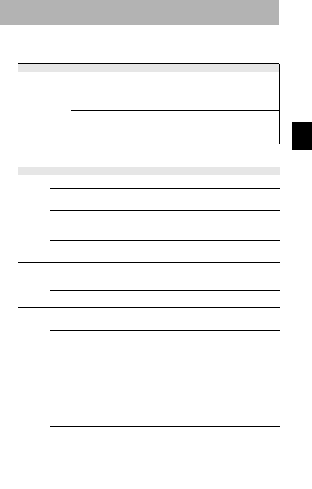
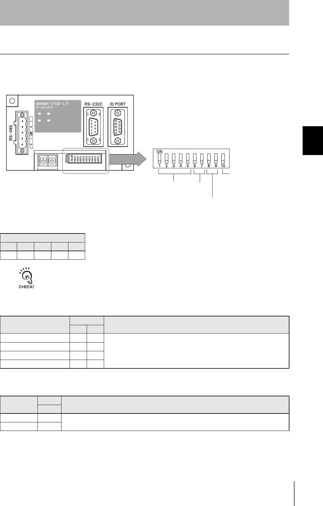
Set the Communications Conditions for Amplifier Units
Set the communications conditions using the DIP switches on the side face of the Amplifier Unit.
After changing the DIP switch settings, restart the system. The new settings will not become effective until the
system is restarted.
Baud rate
Option DIP-SW Description
6 7
38400 bps ON ON Use a consistent baud rate setting within the same system configuration.
19200 bps OFF ON
9600 bps (default setting) OFF OFF
4800 bps ON OFF
RS-485 terminator
Option DIP-SW Description
10
Invalid OFF Set "ON" at both of the end units in a multidrop system, and "OFF" at all the other units. If there is only one
unit, set "ON."
If there is a possibility that one of multiple Amplifier Units in use may be used independently, turn the termi-
nators of all the Amplifier Units OFF and fit external terminators close to the units at both ends.
Valid ON
Node No. Baud rate
Always OFF
(Not used in this CIDRW system)
RS-485 terminator
Node No.
Node No. DIP-SW
12345
01 OFF OFF OFF OFF OFF
02 ON OFF OFF OFF OFF
03 OFF ON OFF OFF OFF
04 ON ON OFF OFF OFF
05 OFF OFF ON OFF OFF
06 ON OFF ON OFF OFF
07 OFFONONOFFOFF
08 ON ON ON OFF OFF
09 OFF OFF OFF ON OFF
10 ON OFF OFF ON OFF
11 OFF ON OFF ON OFF
12 ON ON OFF ON OFF
13 OFF OFF ON ON OFF
14 ON OFF ON ON OFF
15 OFFONONONOFF
16 ON ON ON ON OFF
Node No. DIP-SW
1 2 3 4 5
17 OFFOFFOFFOFFON
18 ON OFF OFF OFF ON
19 OFF ON OFF OFF ON
20 ON ON OFF OFF ON
21 OFF OFF ON OFF ON
22 ON OFF ON OFF ON
23 OFF ON ON OFF ON
24 ON ON ON OFF ON
25 OFFOFFOFFON ON
26 ON OFF OFF ON ON
27 OFF ON OFF ON ON
28 ON ON OFF ON ON
29 OFF OFF ON ON ON
30 ON OFF ON ON ON
31 OFFONONONON
Setting not possible
ON ON ON ON ON
A
lways set node numbers that are unique within the system configuration. When SECS is used, the node number set here is
"HeadID(E99)."

62
SECTION 3
Set the Communications Conditions for Amplifier Units
CIDRW System
User’s Manual
SECTION 3
Preparing for Communications
Communications conditions
Item Specifications
Standard conformed to RS-232C
Communications con-
trol protocol
1:N protocol exclusive to OMRON
Synchronization
method
Start-stop synchronization
Baud rate Set using a DIP switch
Frame composition Start bit Data bits Parity bit Stop bit Total
1 8 None 1 10
Error detection FCS (frame check sequence)
63
CIDRW System
User’s Manual
SECTION 3
Set the Communications Conditions for Link Units
SECTION 3
Preparing for Communications
Set the Communications Conditions for Link Units
Set the communications conditions by setting the DIP switches.
The node numbers for Link Units are fixed. Check that DIP switches 1to 5 are all ON.
Node No. (fixed)
DIP-SW
12345
ON ON ON ON ON
Baud rate
Option DIP-SW Description
6 7
38400 bps ON ON Use a consistent baud rate setting within the same system configuration.
19200 bps OFF ON
9600 bps (default setting) OFF OFF
4800 bps ON OFF
RS-485 terminator
Option DIP-SW Description
10
Invalid OFF Set "ON".
Valid ON
Node No. Baud rate
Always OFF
(Not used in this CIDRW system)
RS-485 terminator

64
SECTION 3
Set the Communications Conditions for Link Units
CIDRW System
User’s Manual
SECTION 3
Preparing for Communications
Communications conditions
Item Specifications
Standard conformed to RS-232C
Communications con-
trol protocol
1:N protocol exclusive to OMRON
Synchronization
method
Start-stop synchronization
Baud rate Set using a DIP switch
Frame composition Start bit Data bits Parity bit Stop bit Total
1 8 None 1 10
Error detection FCS (frame check sequence)
65
CIDRW System
User’s Manual
SECTION 3
Communications Test
SECTION 3
Preparing for Communications
Communications Test
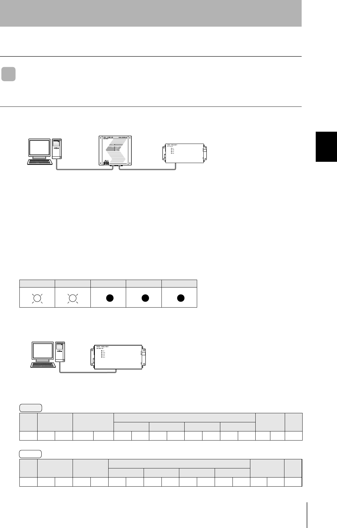
Test for Communications with the Host Device
Check if the host device, CIDRW Controller, and Amplifier Units are correctly connected.
When SECS is Used
• Connection between host device and CIDRW Controller
Send Are You There Request message "S1, F1" from the host device.
If it is correctly connected, On Line Data "S1, F2" will be sent from the CIDRW Controller.
• Connection between the CIDRW Controller and Amplifier Unit
The connection between the CIDRW Controller and Amplifier Unit is checked automatically. If they are
connected correctly, the operation indicators on the CIDRW Controller light in the manner shown
below.
When SECS is Not Used
Node No.1 is tested with the data "12345678."
POWER OPERATING ALARMS BUSY ERROR
SOH Node No. Command code Test data FCS CR
Data 1 Data 2 Data 3 Data 4
01h01 1 0 12345678080Dh
SOH Node No. Response
code
Test data FCS CR
Data 1 Data 2 Data 3 Data 4
01h010012345678090Dh
CIDRW ControllerHost Amplifier Unit
Amplifier UnitHost
Command
Response
66
SECTION 3
Communications Test
CIDRW System
User’s Manual
SECTION 3
Preparing for Communications
ID Tag ↔ CIDRW System Communications Test
Send a command from the host device and check that normal communication with the ID Tag is possi-
ble.
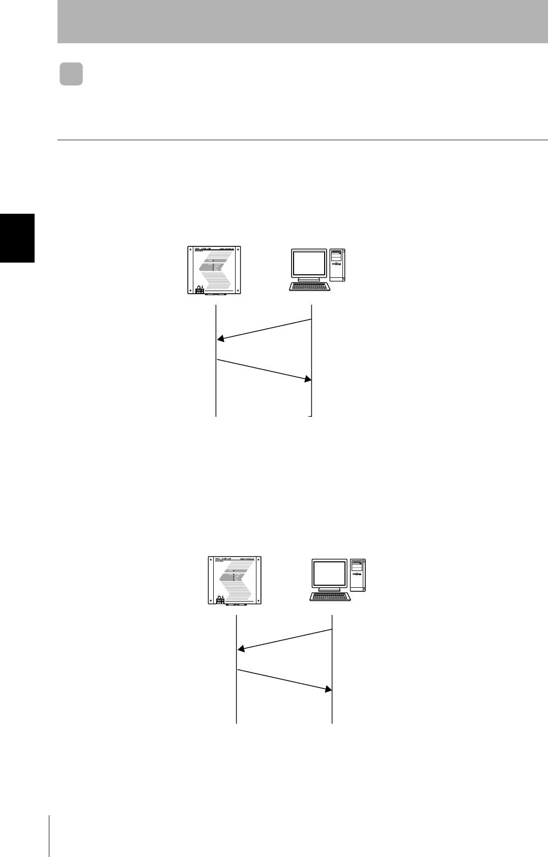
When SECS is Used
• Read ID
The host device sends a Read ID Request message to the CIDRW Controller for Head 1. The CIDRW
Head 1 reads the ID, and the CIDRW Controller returns the ID to the host device.
• Read Data
The host device sends a Read Data Request message to the CIDRW Controller for Head 1, DataSeg
S01 and Datalength 8. The CIDRW Head 1 reads the data, and the CIDRW Controller returns the data
to the host device.
CIDRW Controller Host
S18, F9 Read ID Request
Target ID="01"
S18, F10 Read ID Data
MID="XYZ00001"
CIDRW Controller Host
S18, F5 Read Request
Target ID="01"
Dataseg="S01"
Datalength="8"
S18,F6 Read Data
Data="yyyyyyyy"
67
CIDRW System
User’s Manual
SECTION 3
Communications Test
SECTION 3
Preparing for Communications
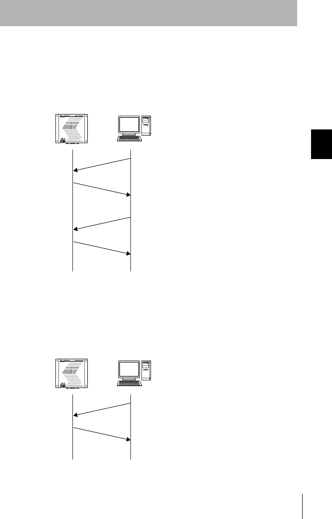
• Write ID
(1) The CIDRW Controller is in IDLE. The host device requests the CIDRW Controller change its oper-
ational status to MAINTENANCE.
(2) The CIDRW Controller changes to MAINTENANCE and replies that it has changed state.
(3) The host device sends a Write ID Request message to the CIDRW Controller for Head 1. The
CIDRW Head 1 writes ID, and the CIDRW Controller returns the ID to the host devices.
• Write Data
The host device sends a Write Data Request message to the CIDRW Controller for Head 1 and Data-
Seg S02. The CIDRW Head 1 writes the data, and the CIDRW Controller returns the results to the host
device.
CIDRW Controller Host
S18, F13 SubSystem Command Request
Target ID="01"
CPVAL="MT"
S18, F14 SubSystem Command Acknowledge
SSACK="NO"
S18, F11 Write ID
Target ID="01"
MID="ABC"
S18, F12 Write ID Data
SSACK="NO"
CIDRW Controller Host
S18, F7 Write ID Request
Target ID="01"
Dataseg="S02"
Data="xxxxxx"
S18, F8 Write Data Acknowledge
SSACK="NO"
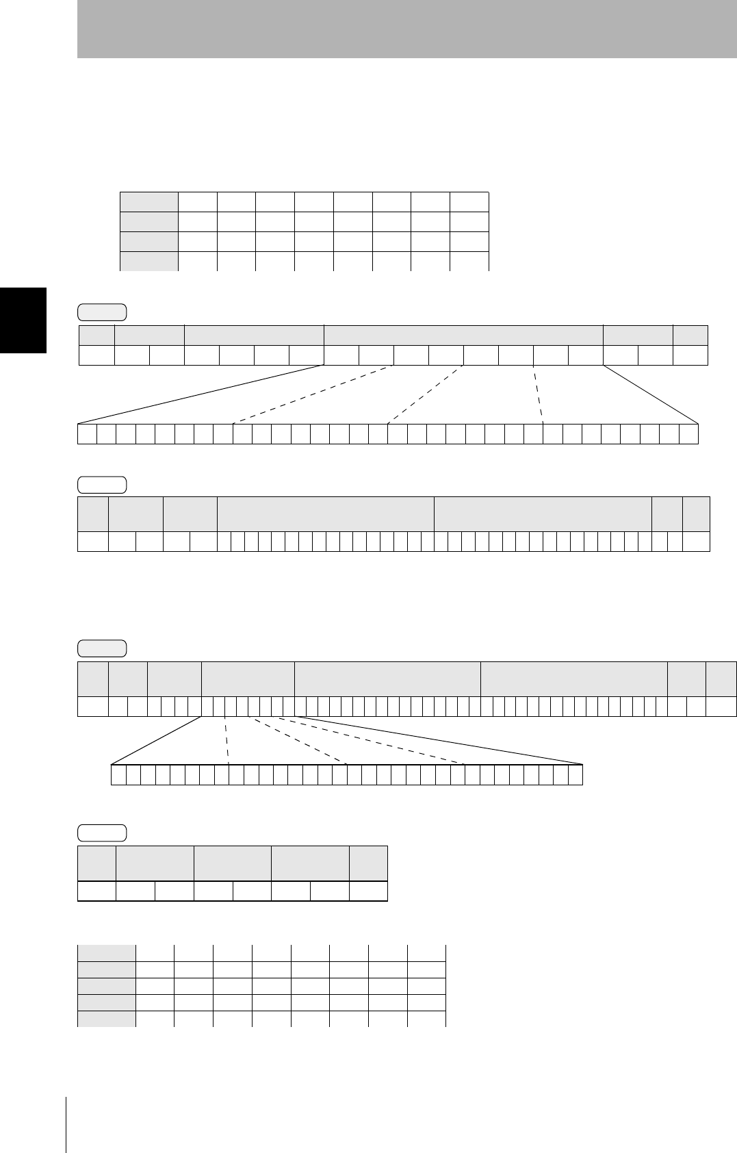
68
SECTION 3
Communications Test
CIDRW System
User’s Manual
SECTION 3
Preparing for Communications
When SECS is Not Used
•Read
Reading the page 1 and page 3 data of node No.1:
•Write
Writing data to page 8 and page 10 of node No.1:
The ID Tag status on normal completion is as shown below:
Data content of the ID Tag
Page 1 12h 34h 56h 78h 90h 12h 34h 56h
Page 2
Page 3 11h 22h 33h 44h 55h 66h 77h 88h
Page 4
SOH Node No. Response
code Page 1 Page 3 FCS CR
01h 0 1 0 0 12345678901234561122334455667788070Dh
SOH Node No. Response
code FCS CR
01h0100010Dh
Page 8 11h 22h 33h 44h 55h 66h 77h 88h
Page 9
Page 10 01h 23h 45h 67h 89h ABh CDh EFh
Command
00000000000000000000000000010100
Binary notation
SOH Node No. Command code Page designation FCS CR
01h01010000000014050Dh
Response
Command
00000000000000000000101000000000
SOH Node
No.
Command
code Page designation Data of page 8 Data of page 10 FCS CR
01h 0 1 0 2 0 000000A0011223344556677880123456789ABCDEF 7 4 0Dh
Binary notation
Response

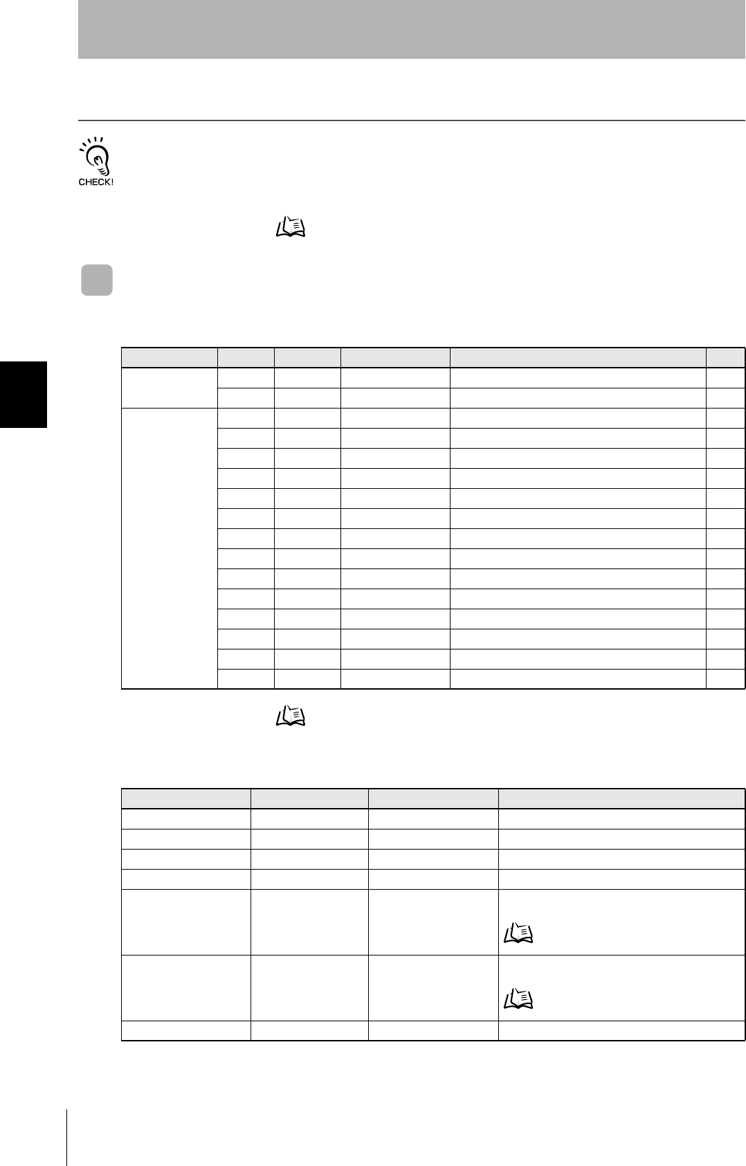
70
SECTION 4
When SECS is Used
CIDRW System
User’s Manual
SECTION 4
Reading from/Writing to ID Tags
When SECS is Used
The SEMI standards are subject to revision: you must refer to the actual standards.
• SEMI E99 THE CARRIER ID READER/WRITER FUNCTIONAL STANDARD
• SEMI E5 EQUIPMENT COMMUNICATION STANDARD 2 MESSAGE CONTENT (SECS II)
• SEMI E4 EQUIPMENT COMMUNICATION STANDARD 1 MESSAGE TRANSFER (SECS I)
SECS Protocol Specifications Refer to page 124.
Message Specifications
List of Error Messages Refer to page 92.
List of Messages Used
Classification S F Direction SECS II names See
General purpose
messages
11 S,H→E,reply Are You There Request p.72
12 S,H←E On Line Data p.72
CIDRW system
messages
18 1 S,H→E,reply Read Attribute Request p.72
18 2 S,H←E Read Attribute Data p.72
18 3 S,H→E,reply Write Attribute Request p.73
18 4 S,H←E Write Attribute Acknowledge p.73
18 5 S,H→E,reply Read Request p.74
18 6 S,H←E Read Data p.74
18 7 S,H→E,reply Write Request p.75
18 8 S,H←E Write Acknowledge p.75
18 9 S,H→E,reply Read ID Request p.76
18 10 S,H←E Read ID Data p.76
18 11 S,H→E,reply Write ID Request p.76
18 12 S,H←E Write ID Acknowledge p.76
18 13 S,H→E,reply Subsystem Command Request p.77
18 14 S,H←E Subsystem Command Acknowledge p.77
Data Item Dictionary
SECS II data items Name Format Value
ATTRID Attribute ID 20 Attribute name
ATTRVAL Attribute value 20 Attribute value
MID Carrier ID MID 2016 - 7E16 (Visible ASCII)
DATA Data 20 All characters 00H-0FFH
DATALENGTH DataSize 52 Offset designation: 1 - 224
Segment designation:
Refer to Data Segment Area page 122.
DATASEG DataSeg 20 Offset designation: "00", "01"..."0222", "0223"
Segment designation:
Refer to Data Segment Area page 122.
STATUS PM information 20 "NE": Normally executed

71
CIDRW System
User’s Manual
SECTION 4
When SECS is Used
SECTION 4
Reading from/Writing to ID Tags
*1: "PS" is an expansion command for this unit.
*2: When the TARGET ID is "00" (CIDRW), this is a zero length item.
*3: "EE," "HE," and "TE" are used only with S18F6, S18F8, S18F10, and S18F12.
S9F7 responses
An S9F7 response is given when a message in an illegal format is received from the host device.
"Illegal format" here means that there is a problem with the message composition, such as illegal attributes, or insuffi-
cient or too many items. If other problems relating to the item contents arise, the response is SSACK = "CE" (commu-
nications error).
SSACK Result status 20 "NO": Normal
"EE": Execution error *3
"CE": Communications error
"HE": Hardware error *3
"TE": Tag error *3
List of STATUS Status L,4
1.<PMInformation>
2.<AlarmStatus>
3.<OperationalStatus>
4.<HeadStatus> *2
The STATUS values are included in the PM
information.
CPVAL State request 20 "OP", "MT", "PS" *1
TARGETID Target ID 20 "00"-"31"
"00" indicates the CIDRW Controller itself.
SSCMD Subsystem com-
mands
20 "ChangeState"
"GetStatus"
"PerformDiagnostics"
"Reset"
Data Item Dictionary
SECS II data items Name Format Value
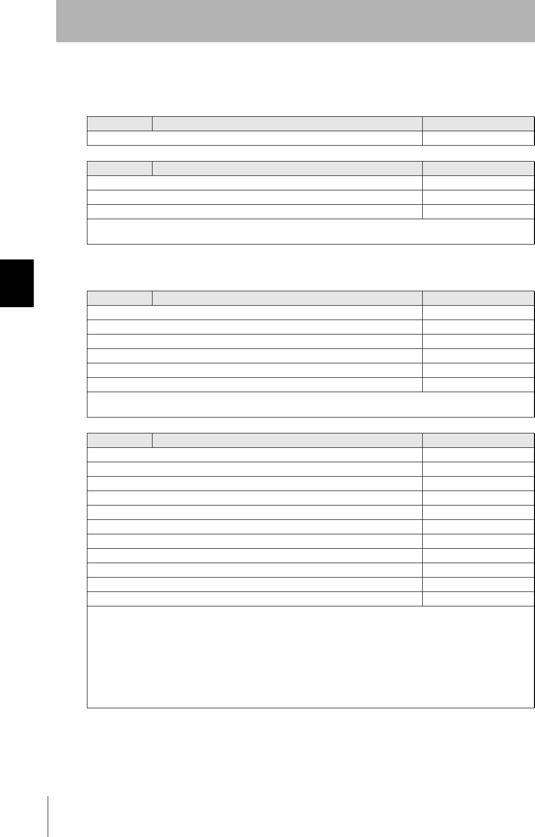
72
SECTION 4
When SECS is Used
CIDRW System
User’s Manual
SECTION 4
Reading from/Writing to ID Tags
Specifications for Each Stream/Function
• Online check
• Get attributes
S1,F1 Are You There Request S,H→E,reply
Header only
S1,F2 On Line Data S,H←E
L,2
1.<MDLN>
2.<SOFTREV>
• Set MDLN (model number).
• Set SOFTREV (software revision level).
S18,F1 Read Attribute Request S,H→E,reply
L,2
1.<TARGETID> "00"-"31"
2.L,n
1.<ATTRID1>
⋅
n.<ATTRIDn>
• The setting for reading all attributes (CIDRW Controller or heads) is n = 0.
S18,F2 Read Attribute Data S,H←E
L,4
1.<TARGETID> "00"-"31"
2.<SSACK>
3.L,n
1.<ATTRVAL1>
⋅
n.<ATTRVALn>
4.L,s
1.<STATUS1>
⋅
s.<STATUSs>
• The order of the attribute data corresponds to the attribute ID specified by S18, F1.
When reading of all attributes is specified, unsupported attribute items (ATTRVAL) are omitted.
• When the specified target is invalid:
n = 0, s = 0, SSACK = "CE" communications error
• When one or more undefined attributes are included:
n = 0, s = 0, SSACK = "CE" communications error
• When head attributes are specified with TARGET = "00" or CIDRW Controller attributes are specified with TARGET <> "00":
n = 0, s = 0, SSACK = "CE" communications error
• If the status of SSACK is other than "NO" (normal), the List of Status will comprise zero items.

73
CIDRW System
User’s Manual
SECTION 4
When SECS is Used
SECTION 4
Reading from/Writing to ID Tags
• Set attributes
F18,F3 Write Attribute Request S,H→E,reply
L,2
1.<TARGETID> "00" (fixed)
2.L,n
1.L,2
1.<ATTRID1>
2.<ATTRVAL1>
n.L,2
1.<ATTRIDn>
2,<ATTRVALn>
Since the attributes for heads are all RO in this system, the target ID is fixed as "00".
S18,F4 Write Attribute Acknowledge S,H←E
L,3
1.<TARGETID> "00" (fixed)
2.<SSACK>
3.L,s
1.<STATUS1>
⋅
s.<STATUSs>
• When the specified target is invalid:
s = 0, SSACK = "CE" communications error
• When one or more undefined attributes or RO attributes are included:
s = 0, SSACK = "CE" communications error
• When illegal attribute data is specified:
s = 0, SSACK = "CE" communications error
• If the status of SSACK is other than "NO" (normal), the List of Status will comprise zero items.
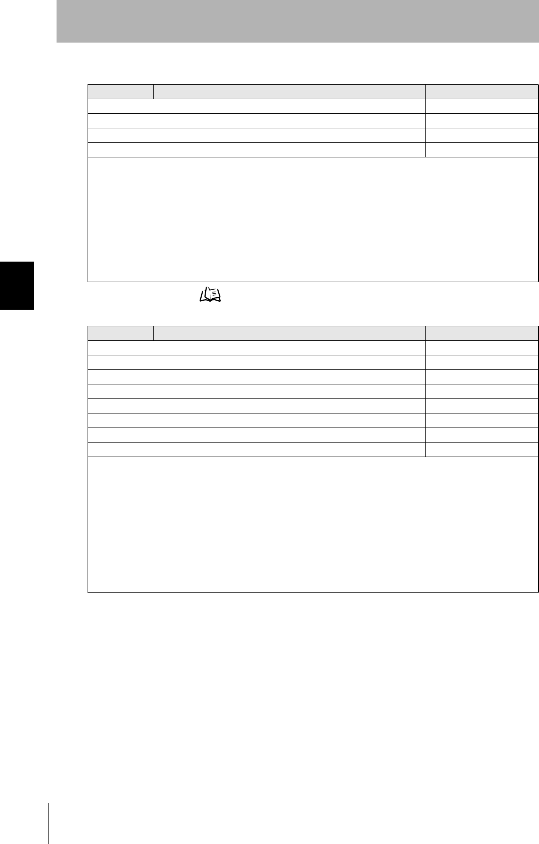
74
SECTION 4
When SECS is Used
CIDRW System
User’s Manual
SECTION 4
Reading from/Writing to ID Tags
• Read data
Data Segment Area Refer to page 122.
S18,F5 Read Request S,H→E,reply
L,3
1.<TARGETID> "01"-"31"
2.<DATASEG>
3.<DATALENGTH>
• When DATASEG is specified as "0" and a character string, the size of data determined by the DATALENGTH setting is read,
starting from the address indicated by the DATASEG setting. If DATALENGTH = 0, data is read up to the end of the data
area.
• If DATASEG is specified as a character string, a size of data determined by DATALENGTH, starting from the address speci-
fied by DATASEG, is read (segment specification).
• When the data of all segments is batch read, both DATASEG and DATALENGTH are omitted (they are zero length items).
• When all the data for a particular segment is read, DATALENGTH is omitted (it is a zero length item).
• In a segment specification, it is not possible to specify a DATALENGTH that exceeds the maximum length of the relevant
DATASEG.
• In a segment specification, if a DATALENGTH that is under the set length for DATASEG is specified, only the data corre-
sponding to specified DATALENGTH is read.
S18,F6 Read Data S,H→E,reply
L,4
1.<TARGETID> "01"-"31"
2.<SSACK>
3.<DATA>
4.L,s
1.<STATUS1>
⋅
s.<STATUSs>
• When the specified target is invalid:
DATA item length = 0, s = 0, SSACK = "CE" communications error
• In an address specification, if:
(SEGMENT + DATALENGTH) ≤ total value for all segments then SSACK = "NO"
• In an address specification, if:
(SEGMENT + DATALENGTH) > total value for all segments then DATA item length = 0, s = 0, SSACK = "CE" communica-
tions error
• In a segment specification, if an undefined DATASEG is specified, or if the DATALENGTH is illegal:
DATA item length = 0, s = 0, SSACK = "CE" communications error
• When reading of all segment data is specified in a system where the data segment is not defined:
DATA length = 0, SSACK = "NO"
• If the status of SSACK is other than "NO" (normal), the List of Status will comprise zero items.
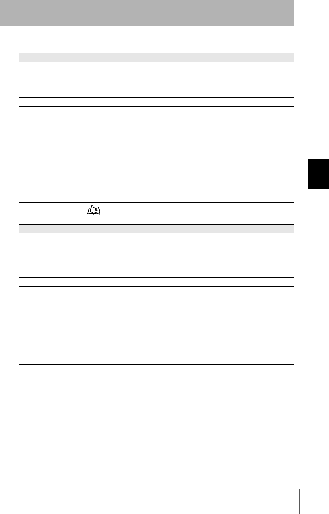
75
CIDRW System
User’s Manual
SECTION 4
When SECS is Used
SECTION 4
Reading from/Writing to ID Tags
• Write data
Data Segment Area Refer to page 122.
S18,F7 Write Request S,H→E,reply
L,4
1.<TARGETID> "01"-"31"
2.<DATASEG>
3.<DATALENGTH>
4.<DATA>
• If DATASEG is specified as "0" and a character string, a size of data corresponding to the DATALENGTH setting and starting
from the address within the data area indicated by the DATASEG setting is written (address specification). If DATALENGTH
= 0, data is written up to the end of the data area.
• If DATASEG is specified as a character string, a size of data determined by DATALENGTH, starting from the address speci-
fied by DATASEG, is written (segment specification).
• When the data for all segments is batch written, both DATASEG and DATALENGTH are omitted (they are zero length items).
• When all the data for a particular segment is written, DATALENGTH is omitted (it is a zero length item).
• In a segment specification, it is not possible to specify a DATALENGTH that exceeds the maximum length of the relevant
DATASEG.
• In a segment specification, if a DATALENGTH that is under the set length for DATASEG is specified, only the data corre-
sponding to the specified DATALENGTH is written, compressed into the smaller addresses.
• The item lengths of DATASEG and DATA must be matched.
• If DATASEG and DATALENGTH are both omitted (made zero length items), the length of DATA must match the total of the
set lengths of all segments.
S18,F8 Write Acknowledge S,H←E
L,3
1.<TARGETID> "01"-"31"
2.<SSACK>
3.L,s
1.<STATUS1>
⋅
s.<STATUSs>
• When the specified target is invalid:
s = 0, SSACK = "CE" communications error
• In an address specification, if:
(SEGMENT + DATALENGTH) ≤ total value for all segments then SSACK = "NO"
• In an address specification, if:
(SEGMENT + DATALENGTH) > total value for all segments then DATA item length = 0, s = 0, SSACK = "CE" (communica-
tions error)
• In a segment specification, if DATASEG and DATALENGTH are illegal:
s = 0, SSACK = "CE" communications error
• If the status of SSACK is other than "NO" (normal), the List of Status will comprise zero items.
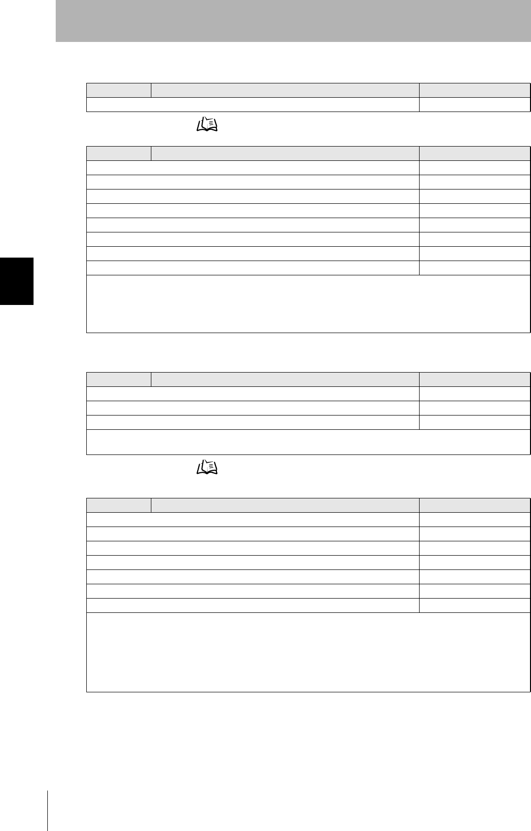
76
SECTION 4
When SECS is Used
CIDRW System
User’s Manual
SECTION 4
Reading from/Writing to ID Tags
• Read ID
Data Segment Area Refer to page 122.
• Write ID
Data Segment Area Refer to page 122.
S18,F9 Read ID Request S,H→E,reply
1.<TARGETID> "01"-"31"
S18,F10 Read ID Data S,H←E
L,4
1.<TARGETID> "01"-"31"
2.<SSACK>
3.<MID>
4.L,s
1.<STATUS1>
⋅
s.<STATUSs>
• If the MID data contains Non-Visible ASCII code:
s = 0, MID item length = 0, SSACK = "EE" execution error
• When the specified target is invalid:
s = 0, MID item length = 0, SSACK = "CE" communications error
• If the status of SSACK is other than "NO" (normal), the List of Status will comprise zero items.
S18,F11 Write ID Request S,H→E,reply
L,2
1.<TARGETID> "01"-"31"
2.<MID>
• If an MID that is under the length set for the CarrierIDlength attribute is specified, an error occurs and the MID data is not
written.
S18,F12 Write ID Acknowledge S,H←E
L,3
1.<TARGETID> "01"-"31"
2.<SSACK>
3.L,s
1.<STATUS1>
⋅
s.<STATUSs>
• When the specified target is invalid:
s = 0, SSACK = "CE" communications error
• When there is an MID length error:
s = 0, SSACK = "CE" communications error
• If the MID data contains Non-Visible ASCII code:
s = 0, SSACK = "EE" execution error
• If the status of SSACK is other than "NO" (normal), the List of Status will comprise zero items.

77
CIDRW System
User’s Manual
SECTION 4
When SECS is Used
SECTION 4
Reading from/Writing to ID Tags
• Subsystem command (ChangeState)
S18,F13 Subsystem Command Request (ChangeState) S,H→E,reply
L,3
1.<TARGETID> "00" (fixed)
2.<SSCMD> "ChangeState"
3.L,1
1.<CPVAL1> "OP", "MT" or "PS"
CPVAL = "PS" is a parameter setting unique to this CIDRW Controller for switching to the Setting mode.
S18,F14 Subsystem Command Acknowledge (ChangeState) S,H←E
L,3
1.<TARGETID> "00"
2.<SSACK>
3.L,s
1.<STATUS1>
⋅
s.<STATUSs>
• When the specified target is invalid:
s = 0, SSACK = "CE" communications error
• When SSCMD is invalid:
s = 0, SSACK = "CE" communications error
• When OperationalStatus is BUSY:
s = 0, SSACK = "EE" execution error
• If the status of SSACK is other than "NO" (normal), the List of Status will comprise zero items.
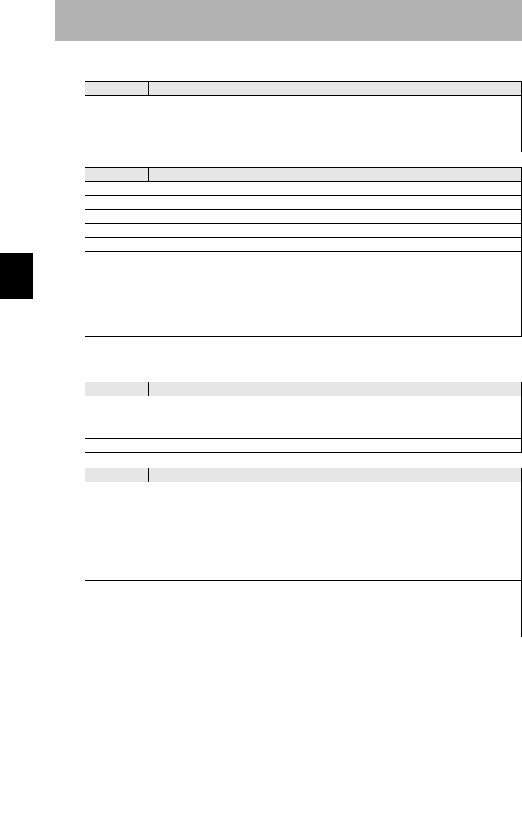
78
SECTION 4
When SECS is Used
CIDRW System
User’s Manual
SECTION 4
Reading from/Writing to ID Tags
• Subsystem command (GetStatus)
• Subsystem command (PerformDiagnostics)
S18,F13 Subsystem Command Request (GetStatus) S,H→Ε,reply
L,3
1.<TARGETID> "00"-"31"
2.<SSCMD> "GetStatus"
3.L,0
S18,F14 Subsystem Command Acknowledge (GetStatus) S,H←E
L,3
1.<TARGETID> "00"-"31"
2.<SSACK> "GetStatus"
3.L,s
1.<STATUS1>
⋅
s.<STATUSs>
• When the specified target is invalid:
s = 0, SSACK = "CE" communications error
• When SSCMD is invalid:
s = 0, SSACK = "CE" communications error
• If the status of SSACK is other than "NO" (normal), the List of Status will comprise zero items.
S18,F13 Subsystem Command Request (PerformDiagnostics) S,H→E,reply
L,3
1.<TARGETID> "00"-"31"
2.<SSCMD> "PerformDiagnostics"
3.L,0
S18,F14 Subsystem command Acknowledge (PerformDiagnostics) S,H←E
L,3
1.<TARGETID> "00"-"31"
2.<SSACK>
3.L,s
1.<STATUS1>
⋅
s.<STATUSs>
• When the specified target is invalid:
s = 0, SSACK = "CE" communications error
• When SSCMD is invalid:
s = 0, SSACK = "CE" communications error
• If the status of SSACK is other than "NO" (normal), the List of Status will comprise zero items.

79
CIDRW System
User’s Manual
SECTION 4
When SECS is Used
SECTION 4
Reading from/Writing to ID Tags
• Subsystem command (Reset)
S18,F13 Subsystem Command Request (Reset) S,H→E,reply
L,3
1.<TARGETID> "00" (fixed)
2.<SSCMD> "Reset"
3.L,0
S18,F14 Subsystem Command Acknowledge (Reset) S,H←E
L,3
1.<TARGETID> "00"
2.<SSACK>
3.L,0
• When the specified target is invalid:
SSACK = "CE" communications error
• When SSCMD is invalid:
SSACK = "CE" communications error

80
SECTION 4
When SECS is Used
CIDRW System
User’s Manual
SECTION 4
Reading from/Writing to ID Tags
Operation Conditions
The response messages and response codes (SSACK) in each state are shown below:
State Initializing Operating Maintenance
Message Function IDLE BUSY
S1,F1 OnlineRequest S1,F0 S1,F2 S1,F2 S1,F2
S18,F11 WriteID S18,F0 S18,F0 S18,F0 NO
S18,F7 WriteData S18,F0 NO NO S18,F0
S18,F3 SetAttribute S18,F0 NO NO NO
S18,F13(Reset) Reset S18,F0 NO NO NO
S18,F9 ReadID S18,F0 NO NO NO
S18,F5 ReadData S18,F0 NO NO S18,F0
S18,F13(PerformDiagnostics) Diagnostics S18,F0 NO NO NO
S18,F13(GetStatus) GetStatus S18,F0 NO NO NO
S18,F1 GetAttribute S18,F0 NO NO NO
S18,F13(ChangeState) ChangeState(to MT) S18,F0 NO S18,F0 S18,F0
S18,F13(ChangeState) ChangeState(to OP) S18,F0 S18,F0 S18,F0 NO
S18,F13(ChangeState) ChangeState(to PS) S18,F0 NO S18,F0 NO
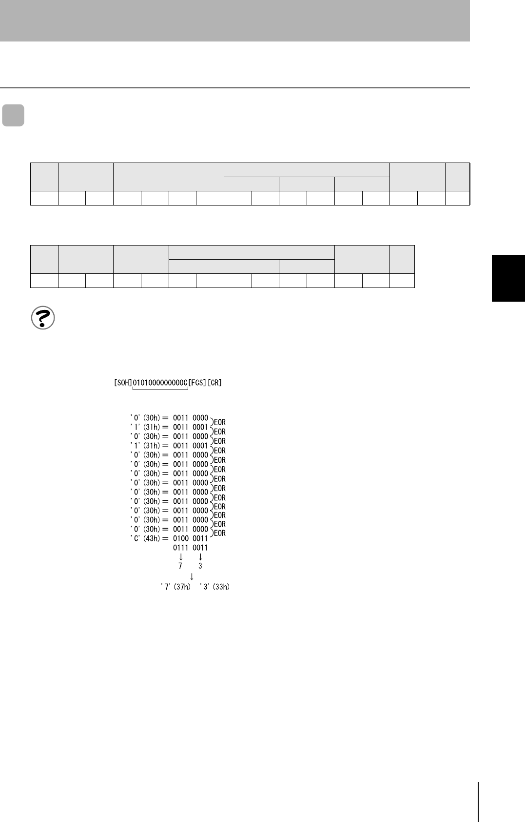
81
CIDRW System
User’s Manual
SECTION 4
When SECS is Not Used
SECTION 4
Reading from/Writing to ID Tags
When SECS is Not Used
Command/Response Format
Meaning of FCS (frame check sequence)
This is two ASCII code characters obtained by conversion from the 8-bit exclusive logical sum (EOR) of the characters
from the character immediately after SOH to the character immediately before FCS.
Example: Reading the data of page 1 and page 2 of node No.1:
Command
SOH Node No. Command code Parameter FCS CR
1 ⋅ ⋅ ⋅ n
01h 0Dh
Response
SOH Node No. Response
code
Parameter FCS CR
1 ⋅ ⋅ ⋅ n
01h 0Dh
Command
Calculation range
(ASCII conversion)
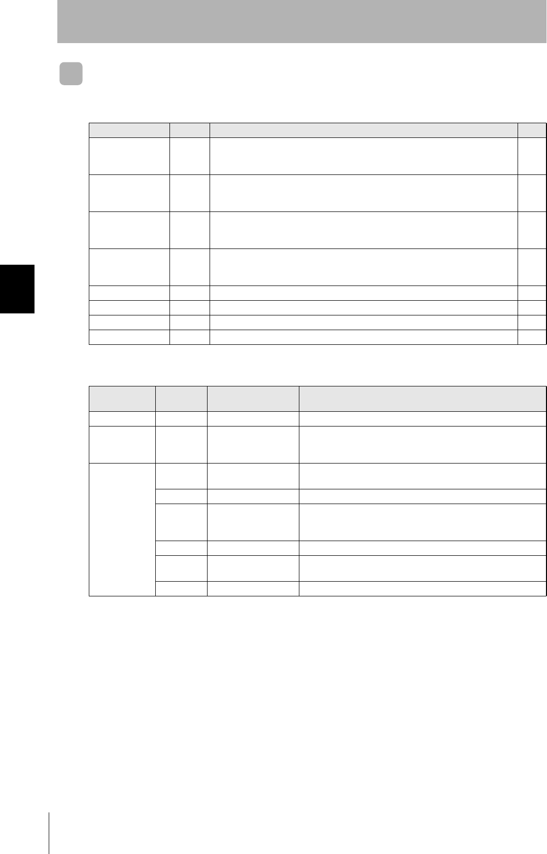
82
SECTION 4
When SECS is Not Used
CIDRW System
User’s Manual
SECTION 4
Reading from/Writing to ID Tags
Command
Command code list
Name Value Function See
READ 0100 When this command is received, the system communicates with the ID Tag, and
reads the specified page(s) of data. Any pages up to a maximum of 16 can be
selected.
p.83
WRITE 0200 When this command is received, the system communicates with the ID Tag, and
writes the specified page(s) of data. Any pages up to a maximum of 16 can be
selected.
p.84
Same Write 0300 When this command is received, the system communicates with the ID Tag, and
writes the same data in page units to the specified pages. Up to 17 pages, which is
the maximum number of pages for an ID Tag, can be specified.
p.86
Byte Write 0400 When this command is received the system communicates with the ID Tag, and
writes data to the area specified by a first address and number of bytes. A maximum
of 128 bytes can be specified.
p.87
TEST 10 Sends received data to the host device. p.88
NAK 12 Sends the response made immediately before again. p.89
Noise measurement 40 Measures the noise in the vicinity of the CIDRW Head. p.89
RESET 7F Resets the Amplifier Unit. p.89
Response code list
Type Response
code Name Description
Normal end 00 Normal end Command execution is completed normally.
Host communi-
cations error
14 Format error There is a mistake in the command format.
(E.g. the command code is undefined, or the page or address spec-
ification is inappropriate.)
Communica-
tions error
70 Communications error Noise or another hindrance occurs during communication with an
ID Tag, and communications cannot be completed normally.
71 Verification error Correct data cannot be written to an ID Tag.
72 No Tag error Either there is no ID Tag in front of the CIDRW Head, or the CIDRW
Head is unable to detect the ID Tag due to environmental factors
(e.g. noise).
7B Outside write area error Writing is not completed normally.
7E ID system error (1) The ID Tag is in a status where it cannot execute command pro-
cessing.
7F ID system error (2) An inapplicable ID Tag has been used.
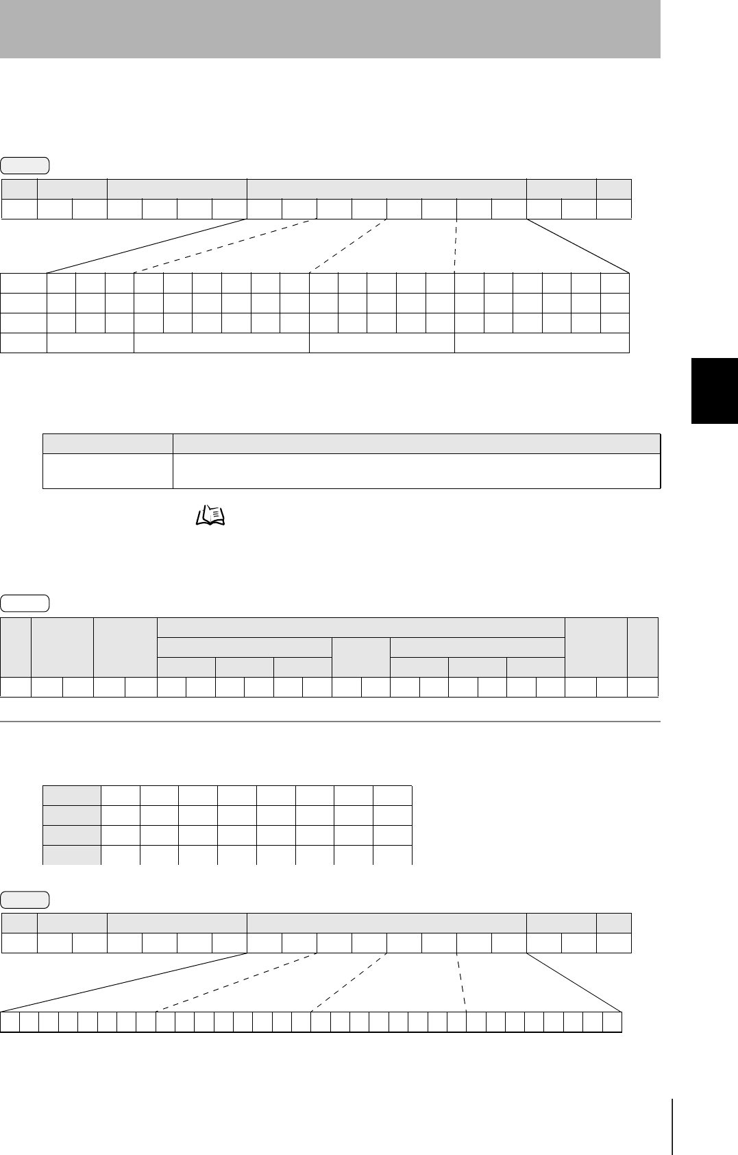
83
CIDRW System
User’s Manual
SECTION 4
When SECS is Not Used
SECTION 4
Reading from/Writing to ID Tags
READ
Reads any pages of data from the ID Tag. The maximum number of pages that can be read at one
time is 16.
Data Segment Area Refer to page 122.
The response code (when normal: 00) and the data in the specified pages are returned in ascending order of
page numbers.
Example: Reading the data of pages 1 and 3 of node No.1
Parameter description
Parameter Description
Page designation Pages are specified by setting the bits corresponding to pages that are to be read to "1" and setting
the other bits to "0", then converting the result to a hexadecimal character string.
SOH Node No. Response
code
Read data
FCS CRPage n ⋅ ⋅ ⋅ Page m (n<m)
Data 1 ⋅ ⋅ ⋅ Data 8 Data 1 ⋅ ⋅ ⋅ Data 8
01h 0 0 0Dh
Data content of the ID Tag
Page 1 12h 34h 56h 78h 90h 12h 34h 56h
Page 2
Page 3 11h 22h 33h 44h 55h 66h 77h 88h
Page 4
Command
Bit 7-07-321076-1076-210
PageSys-SysSys-Sys1716151413-8765-1SysSys
Designation 0* 0* 0* 0* 0* 0/1 0/1 0/1 0/1 0/1 ••• 0/1 0/1 0/1 0/1 ••• 0/1 0* 0*
Value 00 00 - 07 00 - FF 00 - FC
* Always specify 0. If you specify 1 an error (Response code : 14) will occur.
SOH Node No. Command code Page designation (8 characters) FCS CR
01h 0100 0Dh
Response
Command
00000000000000000000000000010100
Binary notation
SOH Node No. Command code Page designation FCS CR
01h01010000000014050Dh
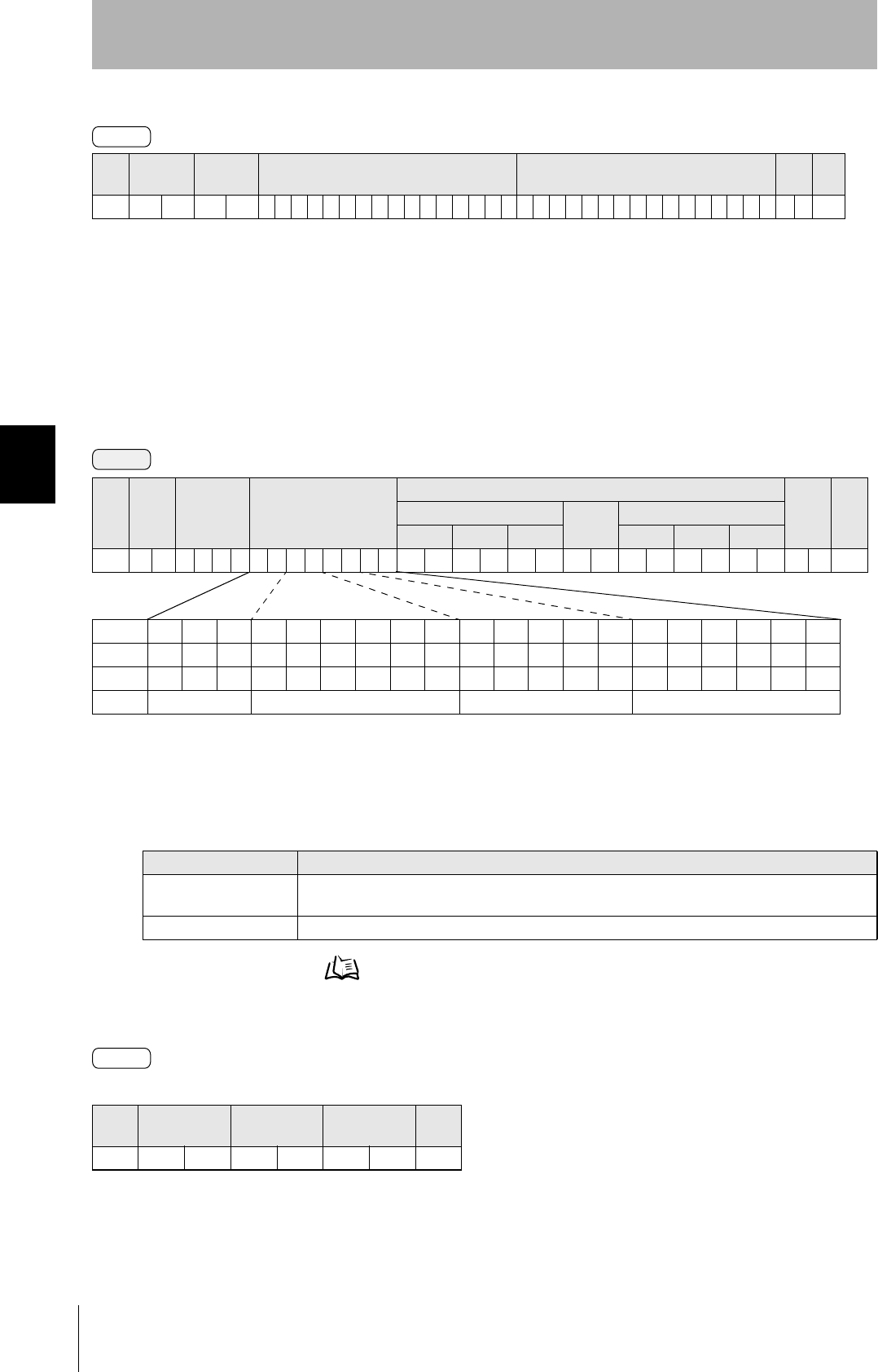
84
SECTION 4
When SECS is Not Used
CIDRW System
User’s Manual
SECTION 4
Reading from/Writing to ID Tags
WRITE
Data is written in page units to the ID Tag. Any page(s) can be specified. It is possible to write to a
maximum of 16 pages at one time.
Data Segment Area Refer to page 122.
The response code (when normal: 00) is returned.
SOH Node No. Response
code Page 1 Page 3 FCS CR
01h 0 1 0 0 12345678901234561122334455667788070Dh
Parameter description
Parameter Description
Page designation Pages are specified by setting the bits corresponding to pages that are to be read to "1" and setting
the other bits to "0", then converting the result to a hexadecimal character string.
Write data The data to be written to the specified pages is specified in ascending order of page numbers.
SOH Node No. Response
code FCS CR
01h 0 0 0Dh
Response
Command
Bit 7-07-321076-1076-210
PageSys-SysSys-Sys1716151413-8765-1SysSys
Designation 0* 0* 0* 0* 0* 0/1 0/1 0/1 0/1 0/1 ••• 0/1 0/1 0/1 0/1 ••• 0/1 0* 0*
Value 00 00 - 07 00 - FF 00 - FC
* Always specify 0. If you specify 1 an error (Response code : 14) will occur.
SOH Node
No.
Command
code
Page designation
(8 characters)
Write data
FCS CRPage n ⋅ ⋅ ⋅ Page m (n<m)
Data 1 ⋅ ⋅ ⋅ Data 8 Data 1 ⋅ ⋅ ⋅ Data 8
01h 0200 0DH
Response
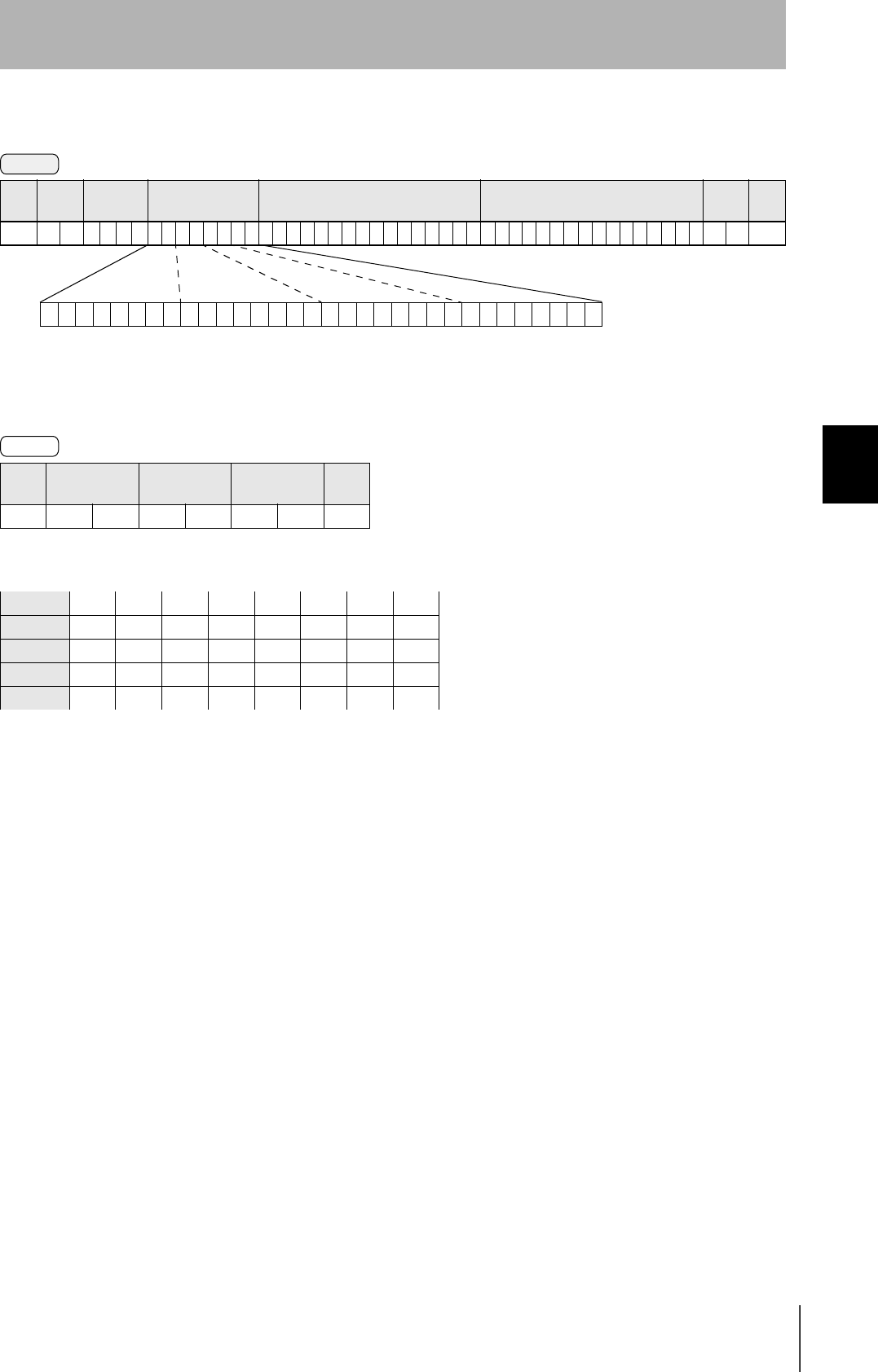
85
CIDRW System
User’s Manual
SECTION 4
When SECS is Not Used
SECTION 4
Reading from/Writing to ID Tags
Example: Writing data to pages 8 and 10 of node No.1:
The ID Tag status on normal completion is as shown below:
SOH Node No. Response
code FCS CR
01h0100010Dh
Page 8 11h 22h 33h 44h 55h 66h 77h 88h
Page 9
Page 10 01h 23h 45h 67h 89h ABh CDh EFh
Command
00000000000000000000101000000000
SOH Node
No.
Command
code
Page designation Data of page 8 Data of page 10 FCS CR
01h 0 1 0 2 0 000000A0011223344556677880123456789ABCDEF 7 4 0Dh
Binary notation
Response
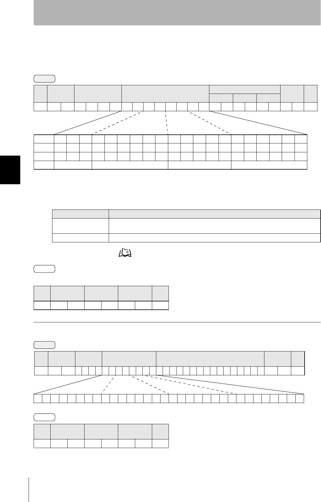
86
SECTION 4
When SECS is Not Used
CIDRW System
User’s Manual
SECTION 4
Reading from/Writing to ID Tags
Same Write
Writes the same data to multiple pages of an ID Tag.
Any page(s) can be specified.
Data Segment Area Refer to page 122.
The response code (when normal: 00) is returned.
Example: Clearing pages 1 to 17 of node No.1 to 0:
Parameter description
Parameter Description
Page designation Pages are specified by setting the bits corresponding to pages that are to be read to "1" and setting
the other bits to "0", then converting the result to a hexadecimal character string.
Write data Specify the write data.
SOH Node No. Response
code FCS CR
01h 0 0 0Dh
SOH Node No. Response
code FCS CR
01h0100010Dh
Command
SOH Node No. Command code Page designation (8 characters) Write data FCS CR
Data 1 ⋅ ⋅ ⋅ Data 8
01h 0 3 0 0 0DH
Bit 7-07-321076-1076-210
PageSys-SysSys-Sys1716151413-8765-1SysSys
Designation 0* 0* 0* 0* 0* 0/1 0/1 0/1 0/1 0/1 ••• 0/1 0/1 0/1 0/1 ••• 0/1 0* 0*
Value 00 00 - 07 00 - FF 00 - FC
* Always specify 0. If you specify 1 an error (Response code : 14) will occur.
Response
Command
00000000000001111111111111111100
Binary notation
SOH Node No. Command
code Page designation Write data FCS CR
01h 0 1 03000007FFFC0000000000000000 0 0 0Dh
Response
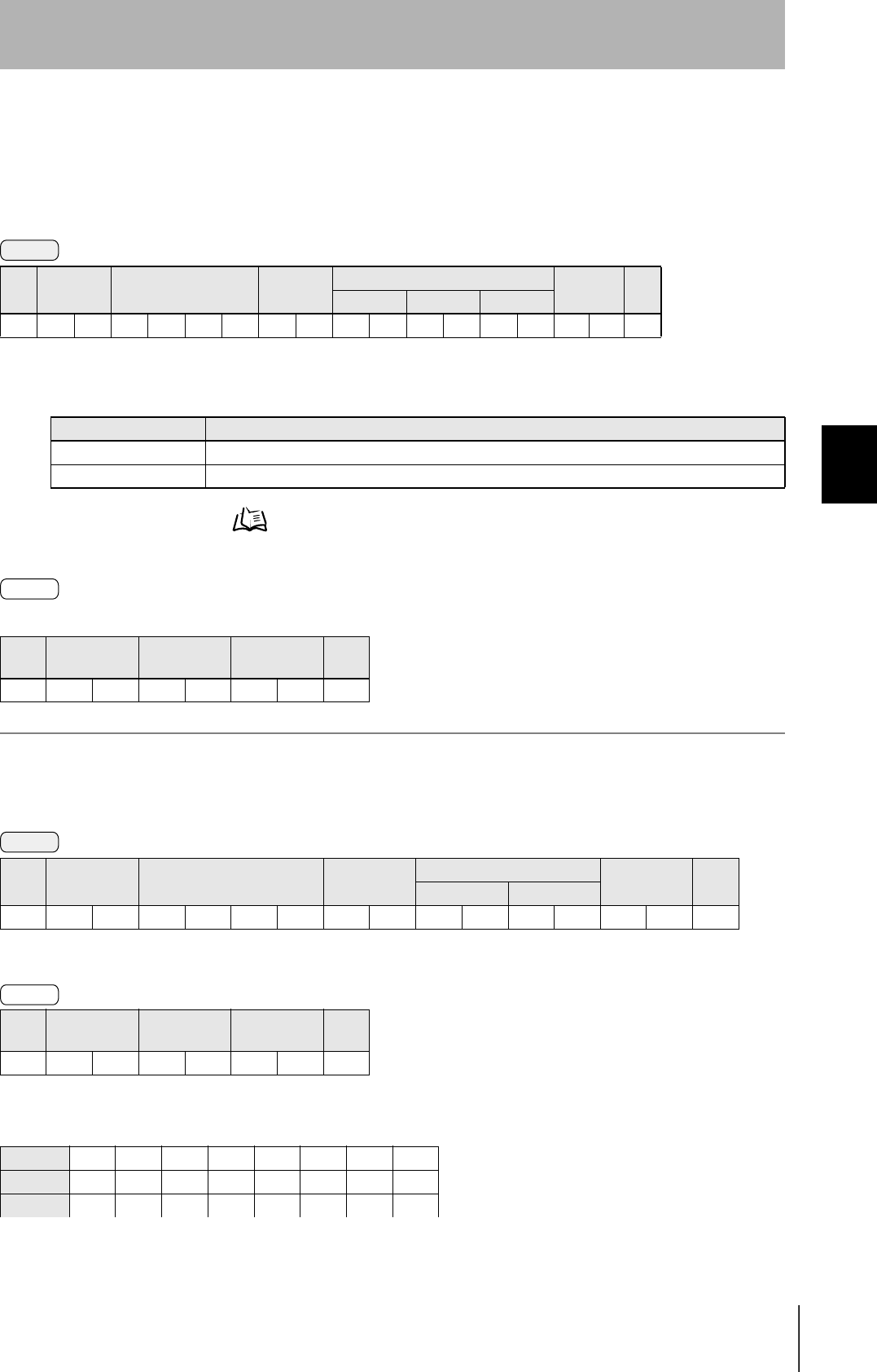
87
CIDRW System
User’s Manual
SECTION 4
When SECS is Not Used
SECTION 4
Reading from/Writing to ID Tags
Byte Write
Writes data to any specified number of bytes starting from the address specified in the ID Tag.
The maximum number of bytes that can be written at one time is 128.
* Data number n = number of bytes written to (2-character units)
Data Segment Area Refer to page 122.
The response code (when normal: 00) is returned.
Example: Writing to two bytes starting from address 05h of node No.1:
The ID Tag status on normal completion is as shown below:
SOH Node No. Command code First
address
Write data FCS CR
Data 1 ••• Data n
01h 0400 0Dh
Parameter description
Parameter Description
Address designation Addresses can be specified in the range 00h to 87h.
Write data Up to 128 bytes of write data, starting from the specified address, can be specified.
SOH Node No. Response
code FCS CR
01h 0 0 0Dh
SOH Node No. Command code First address Write data FCS CR
Data 1 Data 2
01h010400051234040Dh
SOH Node No. Response
code FCS CR
01h0100010Dh
Page 1 12h 34h
Page 2
Command
Response
Command
Response
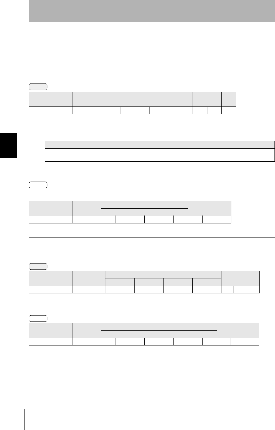
88
SECTION 4
When SECS is Not Used
CIDRW System
User’s Manual
SECTION 4
Reading from/Writing to ID Tags
TEST
Performs a communication test on communications between the host device and Amplifier Unit.
When an Amplifier Unit receives a test command, it sends the response code and command test data
to the host device as the response.
* Number of data n < 136 (2-character units)
The response code (when normal: 00) and the received test data are returned.
Example: Testing by sending the data "12345678" to node No.1:
SOH Node No. Command code Test data FCS CR
Data 1 ••• Data n
01h 1 0 0Dh
Parameter description
Parameter Description
Test data The data to be sent in the test is specified with a hexadecimal value. (Max. 270 characters)
However, note that odd numbers of characters cannot be used.
SOH Node No. Response
code
Test data FCS CR
Data 1 ••• Data n
01h 0 0 0Dh
SOH Node No. Command code Test data FCS CR
Data 1 Data 2 Data 3 Data 4
01h01 1 0 12345678080Dh
SOH Node No. Response
code
Test data FCS CR
Data 1 Data 2 Data 3 Data 4
01h010012345678090Dh
Command
Response
Command
Response
89
CIDRW System
User’s Manual
SECTION 4
When SECS is Not Used
SECTION 4
Reading from/Writing to ID Tags
NAK
Sends the response made immediately before again.
Sends the response made immediately before again.
Noise measurement
The levels of noise in the vicinity of the CIDRW Head are measured and the noise level is expressed
numerically in the range "00" to "99."
The response code (when normal: 00) and the noise level "00" to "99" are returned.
Influence of background noise on communication distance Refer to page 121.
RESET
All Amplifier Unit processing is stopped, and the initial status is re-established.
There is no response to this command.
SOH Node No. Command code FCS CR
01h 1 2 0Dh
SOH Node No. Command code FCS CR
01h 4 0 0Dh
SOH Node No. Response code Noise level FCS CR
01h 0 0 0Dh
SOH Node No. Command code FCS CR
01h 7 F 0Dh
Command
Response
Command
Response
Command
Response

90
SECTION 4
When SECS is Not Used
CIDRW System
User’s Manual
SECTION 4
Reading from/Writing to ID Tags
MEMO

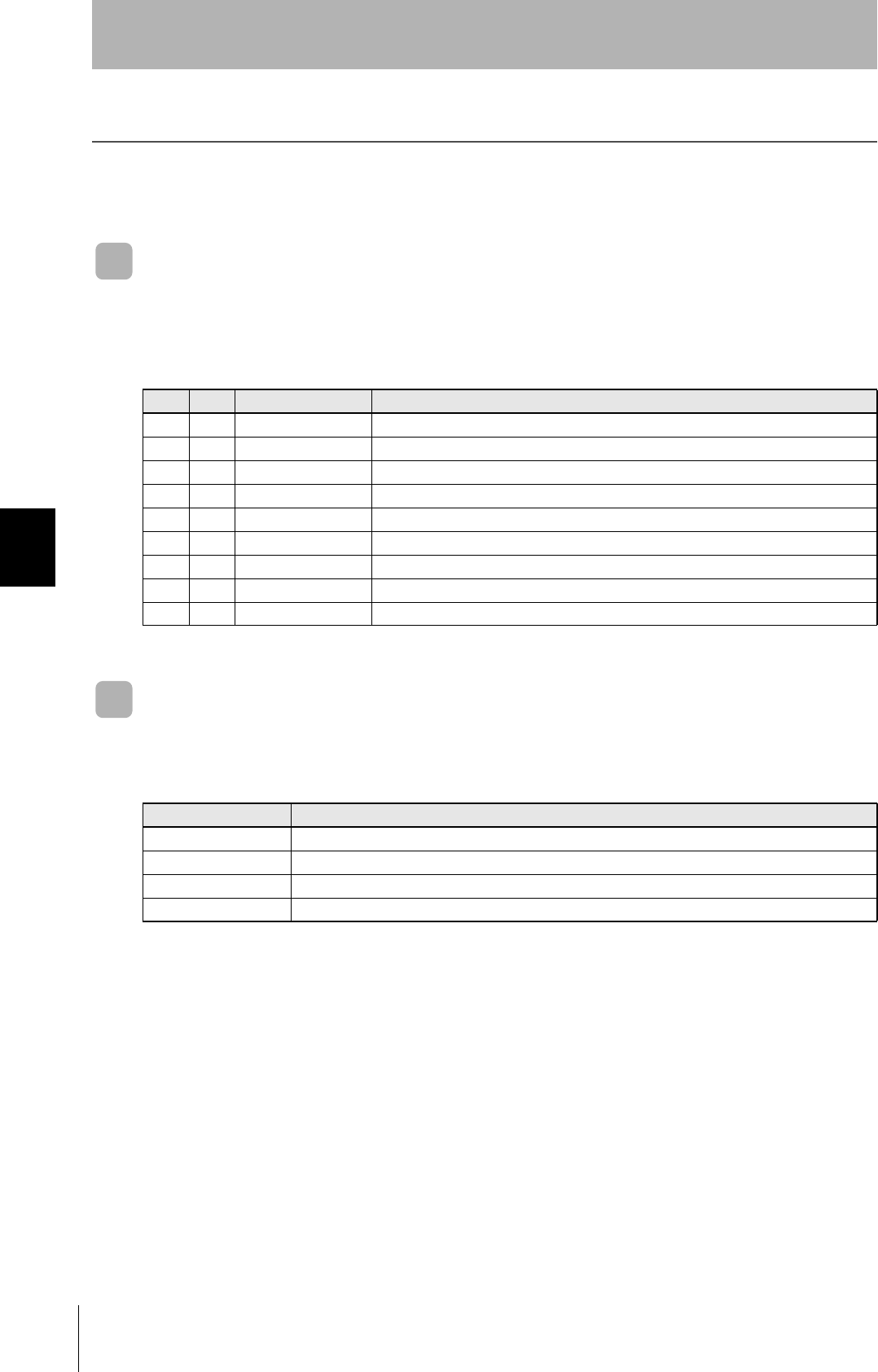
92
SECTION 5
When SECS is Used
CIDRW System
User’s Manual
SECTION 5
Troubleshooting
When SECS is Used
Errors are indicated by the contents of the CIDRW Controller response messages, and by the indicators.
List of Error Messages
When responses are made to messages sent by the CIDRW Controller, errors are expressed by the
contents of error messages and the nature of the SSACK response.
Controller Indicators
If an error or alarm has occurred at the CIDRW Controller, the LEDs on the front of the Controller light.
S F Direction SECS II names
10S,H←E Abort Transaction
90S,H→E Abort Transaction
91S,H←E Unrecognized Device ID
93S,H←E Unrecognized Stream Type
95S,H←E Unrecognized Function Type
97S,H←E Illegal Data
99S,H←E Transaction Timer Timeout
911S,H←E Data Too Long
18 0 S,H←E Abort Transaction
Name Function
OPERATING (green) Lit when the operation status (status model) of the CIDRW system is "operating."
ALARMS (green) Lit when the status of "AlamStatus" of the CIDRW system is "Alarm (1)."
BUSY (green) Lit when the status of "OparationalStatus" of the CIDRW system is "BUSY."
ERROR (red) When a processing error is detected (when SSACK is other than "NO"), this indicator is lit for 50 ms.
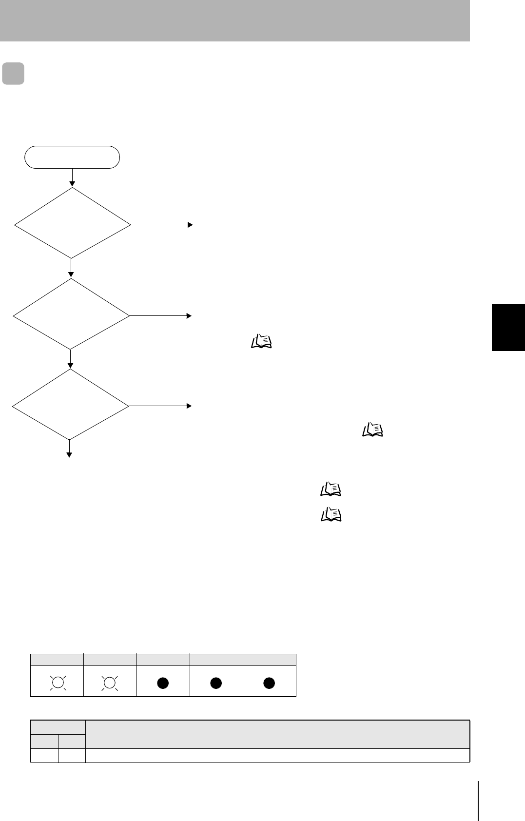
93
CIDRW System
User’s Manual
SECTION 5
When SECS is Used
SECTION 5
Troubleshooting
Operation Check Flowchart
Normal Operation Mode
• Operating normally in the Normal Operation mode
Indicators
POWER OPERATING ALARMS BUSY ERROR
Response
Response Function
S F
— — SSACK="NO"
There is a
response to message
transmission.
(SSNAK = other than
"NO")
Error occurrence
All LEDs are lit
or flashing.
POWER-LED is off.
No
Yes
No
Yes
No
An error has occurred in the CIDRW Controller power supply.
Check the power supply of the CIDRW power supply.
Check the contents of the response message.
When the CIDRW Controller responds to a message transmis-
sion Refer to page 94.
Yes An error has occurred at the CIDRW Controller.
Check the status of the indicators.
When all the LEDs are lit or flashing Refer to page 94.
Check if the settings of the CIDRW Controller and Amplifier Unit are correct.
When the CIDRW Controller fails to respond to messages sent to it Refer to page 95.
When an error unrelated to message transmission and responses occurs Refer to page 95.
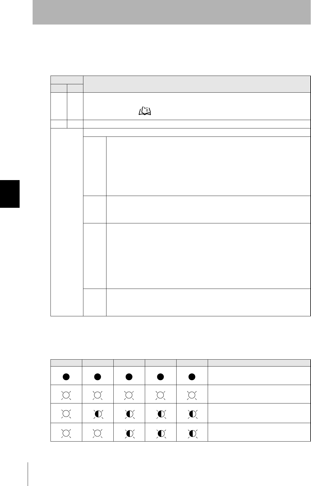
94
SECTION 5
When SECS is Used
CIDRW System
User’s Manual
SECTION 5
Troubleshooting
• When the CIDRW Controller responds to a message transmission
There is a mistake in the message sent to the CIDRW Controller or the Amplifier Unit settings. After
taking the appropriate corrective action, restart the Controller and the Amplifier Unit and send the mes-
sage again.
• When all the LEDs are lit or flashing
An error has occurred in the CIDRW Controller.
After taking the appropriate corrective action, restart the CIDRW Controller.
Response Main check points
S F
— 0 Status conditions when the message was issued (e.g. a Write ID Request message (S18, F11) was sent in
the operating mode, or the message was sent during initial processing)
Operation Conditions Refer to page 80.
9 7 Message composition: illegal attributes, insufficient items, etc.
Other than
above
Ascertain the cause from the contents of the SSACK response.
CE • Mistake in the details of the items in the message
(The node number of an amplifier that is not set was specified as the "TARGET ID," or a segment
name that is not set has been specified for "DATASEG.")
• Connection of RS-485 cables between Amplifier Units (failure to detect Amplifier Units)
• Amplifier Unit baud rate settings (failure to detect Amplifier Units)
• Node numbers of the Amplifier Units (The same number is set for more than one unit, making
detection impossible)
• Cable routing between the host device and CIDRW Controller (influence of background noise)
• Noise levels of the power supply line to the CIDRW Controller
EE • Installation distance/inclination between the ID Tag and CIDRW Head
• Background noise levels of the CIDRW Head
• Installation spacing in relation to CIDRW Heads connected in other CIDRW systems
• When the ID read command is executed, the carrier ID contains non-visible ASCII code.
HE • Mistake in the details of the items in the message
(A segment that does not match the Amplifier Unit specifications has been set; the response
time-out setting is not correct.)
• Connection and wiring of cable between CIDRW Controller and Amplifier Unit
• Power supply to Amplifier Units
• Amplifier Unit terminal resistance settings
• Routing of each cable (influence of background noise)
• Node numbers of the Amplifier Units (the same number is set for more than one unit)
• Amplifier Unit error (hardware error)
• Noise levels of the power supply line
TE • Type/specifications of the ID Tags used
• Settings of the ID Tags used (lock, etc.)
• Environment of use of the ID Tags (ID Tag breakage due to use in unanticipated ways)
• ID Tag overwrite life
POWER OPERATING ALARMS BUSY ERROR Main check points
• Supply of 24 VDC power
• The CIDRW Controller may be damaged.
• Mode switch setting (Is the setting "0"?)
If the error cannot be resolved after checking,
the CIDRW Controller may be damaged.
• The CIDRW Controller may be damaged.
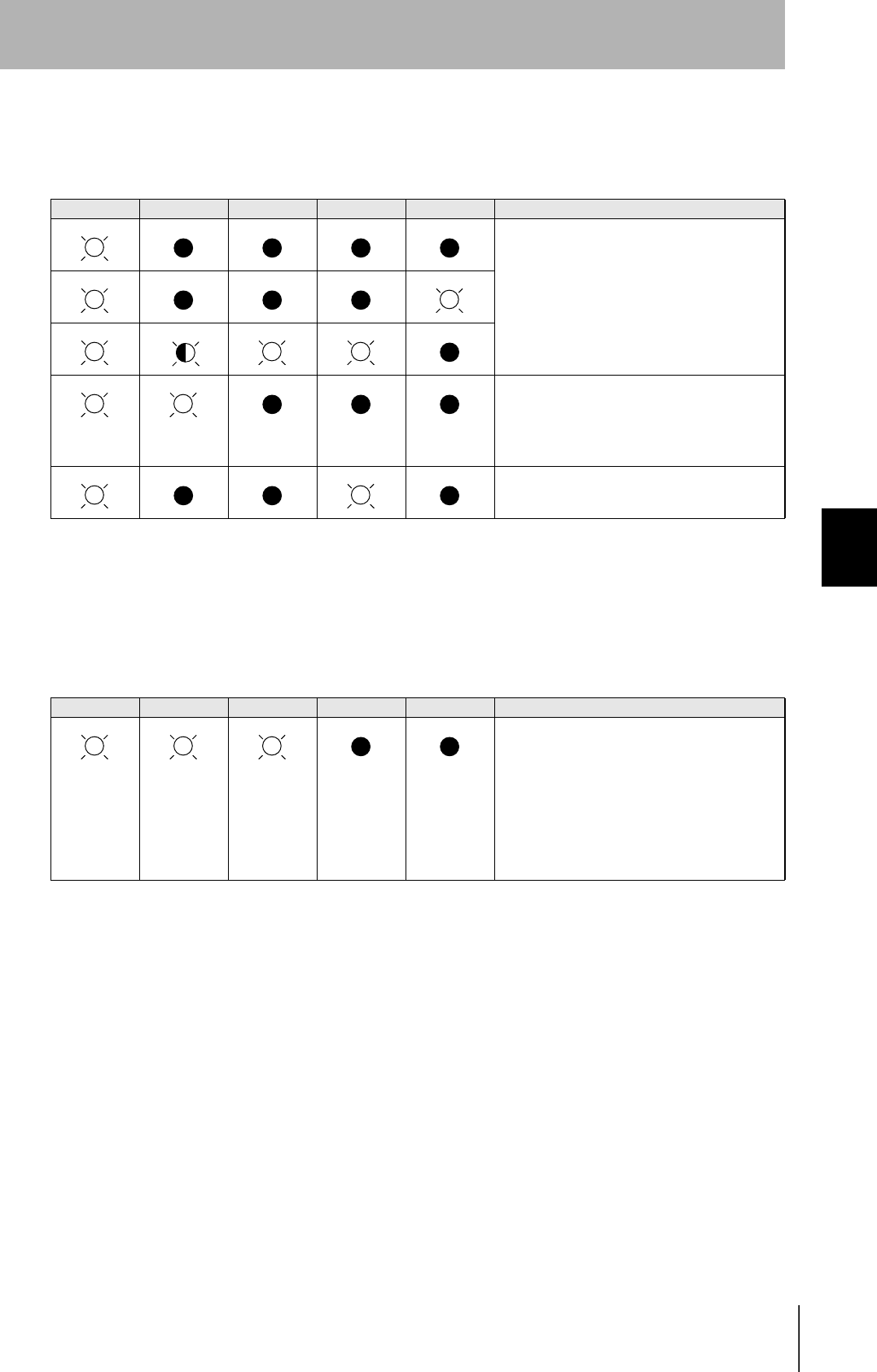
95
CIDRW System
User’s Manual
SECTION 5
When SECS is Used
SECTION 5
Troubleshooting
• When the CIDRW Controller fails to respond to messages sent to it
There is a mistake in the CIDRW Controller or Amplifier Unit settings.
After taking the appropriate corrective action, restart the CIDRW Controller and Amplifier Unit.
• When an error unrelated to message transmission and responses occurs
There is a mistake in the settings of the CIDRW Controller and Amplifier Unit.
After taking the appropriate corrective action, restart the CIDRW Controller and Amplifier Unit.
POWER OPERATING ALARMS BUSY ERROR Main check points
• Mode switch setting (Is the setting "0"?)
• Cable wiring between the CIDRW Controller
and host device
• Communications conditions for communication
between the CIDRW Controller and host
device (baud rate, character composition, etc.)
• Cable wiring between the CIDRW Controller
and host device
• Node numbers of the Amplifier Units (The
same number is set for more than one unit.)
POWER OPERATING ALARMS BUSY ERROR Main check points
• Mode switch setting (Is the setting "0"?)
• Amplifier Unit baud rate settings
• Node numbers of the Amplifier Units (The
same number is set for more than one unit.)
• Connection and wiring of cable between
CIDRW Controller and Amplifier Unit
• Amplifier Unit error (hardware error)
• Routing of each cable (influence of back-
ground noise)
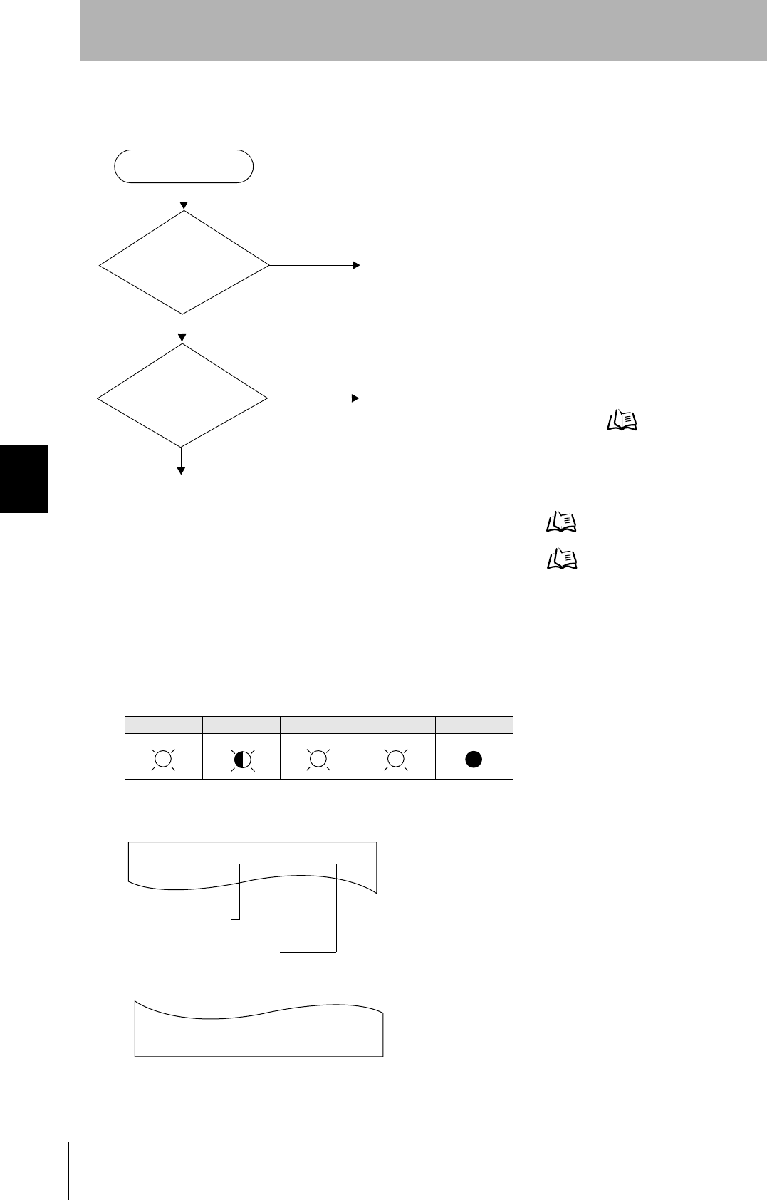
96
SECTION 5
When SECS is Used
CIDRW System
User’s Manual
SECTION 5
Troubleshooting
Setting Mode
• Operating normally in the Setting mode
Terminal initial screen of the host device after startup in the Setting mode
Terminal screen when parameter setting has been completed without error
Indicators
POWER OPERATING ALARMS BUSY ERROR
Error occurrence
All LEDs are lit
or flashing.
POWER-LED is OFF
No
Yes
No
Yes
An error has occurred in the CIDRW Controller power supply.
Check the power supply of the CIDRW Controller.
An error has occurred at the CIDRW Controller.
Check the status of the indicators.
When all the LEDs are lit or flashing Refer to page 97.
Check if the CIDRW Controller settings are correct.
When the CIDRW Controller fails to respond to messages sent to it Refer to page 97.
When an error unrelated to message transmission and responses occurs Refer to page 97.
SETUP_START <L22 ><XXX.XX, YYY.YY>
_
Software Revision Level
Model number
Hardware Revision Level
SETUP_COMPLETE
_
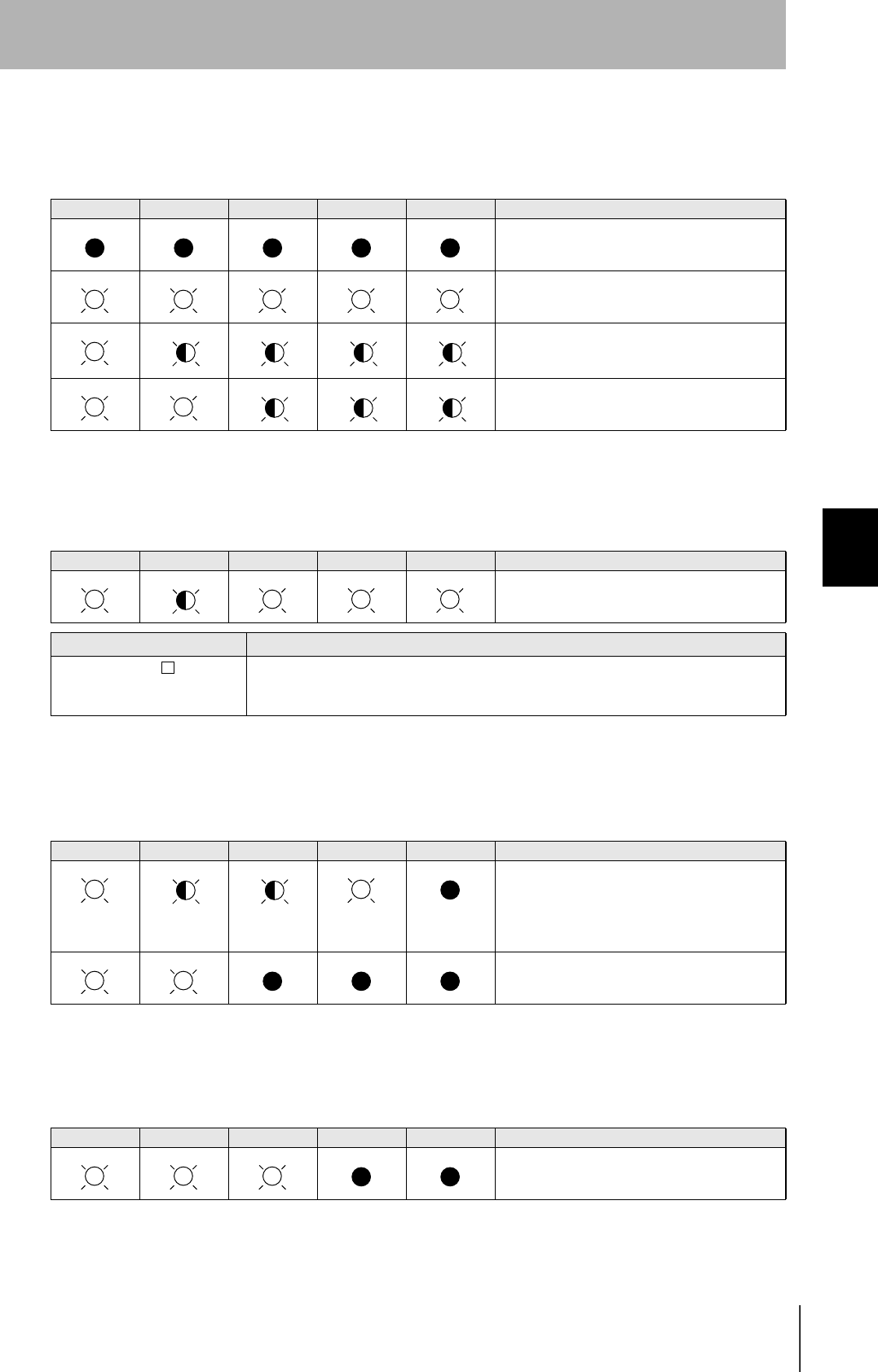
97
CIDRW System
User’s Manual
SECTION 5
When SECS is Used
SECTION 5
Troubleshooting
• When all the LEDs are lit or flashing
An error has occurred in the CIDRW Controller. After taking appropriate corrective action, restart the
CIDRW Controller and check the indicators.
• When the CIDRW Controller responds to a message transmission
There is a mistake in the CIDRW Controller settings or the sent parameters. After taking appropriate
corrective action, restart the CIDRW Controller and check the indicators.
• When the CIDRW Controller fails to respond to messages sent to it
There is a mistake in the CIDRW Controller settings or the sent parameters. After taking appropriate
corrective action, restart the CIDRW Controller and check the indicators.
• When an error unrelated to message transmission and responses occurs
There is a mistake in the settings of the CIDRW Controller or Amplifier Unit. After taking appropriate
corrective action, restart the CIDRW Controller and Amplifier Unit and check the indicators.
POWER OPERATING ALARMS BUSY ERROR Main check points
• Supply of 24 VDC power
• The CIDRW Controller may be damaged.
• Mode switch setting (Is the setting "3"?)
If the error cannot be resolved after checking,
the CIDRW Controller may be damaged.
• The CIDRW Controller may be damaged.
POWER OPERATING ALARMS BUSY ERROR Main check points
• Sent parameters (Are the parameters cor-
rect? Are the settings correct?)
Response Contents
SETUP_FAILED [ ] The parameters are not updated. The figure in square brackets [ ] indicates the line number
where the error was first detected. If a parity error is detected in the received characters,
this figure is [0].
POWER OPERATING ALARMS BUSY ERROR Main check points
• Transmission parameters (Are the parameters
correct?)
• Communications conditions for communication
between the CIDRW Controller and the host
device (baud rate, character composition, etc.)
• Mode switch setting (Is the setting "3"?)
POWER OPERATING ALARMS BUSY ERROR Main check points
• Mode switch setting (Is the setting "3"?)
98
SECTION 5
When SECS is Not Used
CIDRW System
User’s Manual
SECTION 5
Troubleshooting
When SECS is Not Used
Errors are indicated by the presence or absence of a response to an Amplifier Unit command, and by the
indicators.
List of Error Messages
Amplifier Unit Indicators
Type Response
code Name Description
Host communi-
cations error
14 Format error There is a mistake in the command format.
(E.g. the command portion is undefined, or the page or address speci-
fication is inappropriate.)
Communications
error between
the CIDRW Head
and ID Tag
70 Communications
error
Noise or another hindrance has occurred during communication with
an ID Tag, and communications cannot be completed normally.
71 Verification error Correct data cannot be written to an ID Tag.
72 No Tag error Either there is no ID Tag in front of the CIDRW Head, or the CIDRW
Head is unable to detect the ID Tag due to environmental factors (e.g.
noise).
7B Outside write area
error
The ID Tag is at a position where reading is possible but writing is not,
so writing does not complete normally.
7E ID system error (1) The ID Tag is in a status where it cannot execute the command pro-
cessing.
7F ID system error (2) An inapplicable ID Tag has been used.
Name Indications
RUN (green) Turns ON when the Amplifier Unit is in normal operation.
COMM (orange) Turns ON during communications with the host device or during communications with an ID Tag.
NORM (green) Turns On when the communications finish with no error.
ERROR (red) Turns ON when an error occurs during communication with the host device, or during communication with
an ID Tag.
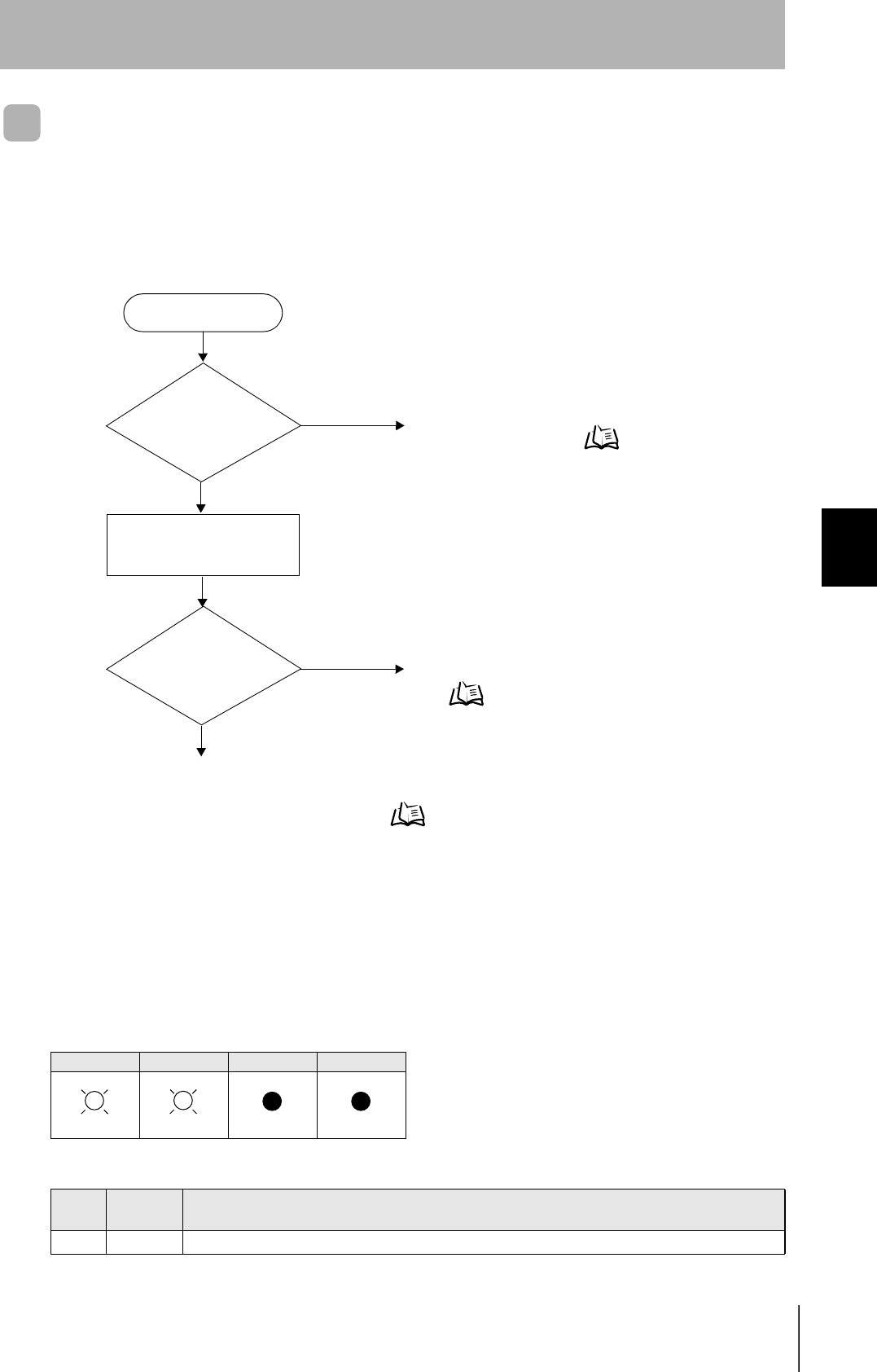
99
CIDRW System
User’s Manual
SECTION 5
When SECS is Not Used
SECTION 5
Troubleshooting
Operation Check Flowchart
From Installation to Trial Operation
Errors are indicated by whether or not a response to the test command is received and by the status of
the Amplifier Unit indicators.
• If the test command was received normally:
Indicators
RUN COMM NORM ERROR
Response code for the response
Type Response
code Function
Normal 00 The command was received normally.
Error occurrence
Test command transmission
RUN-LED is OFF
No
Yes An error has occurred at the Amplifier Unit.
Amplifier Unit error Refer to page 100.
Check if the Amplifier Unit settings are correct.
If there is no response to the command: Refer to page 100.
Response received Yes Check the nature of the response.
If there is a response to the command
Refer to page 100.
No
(Lights once)
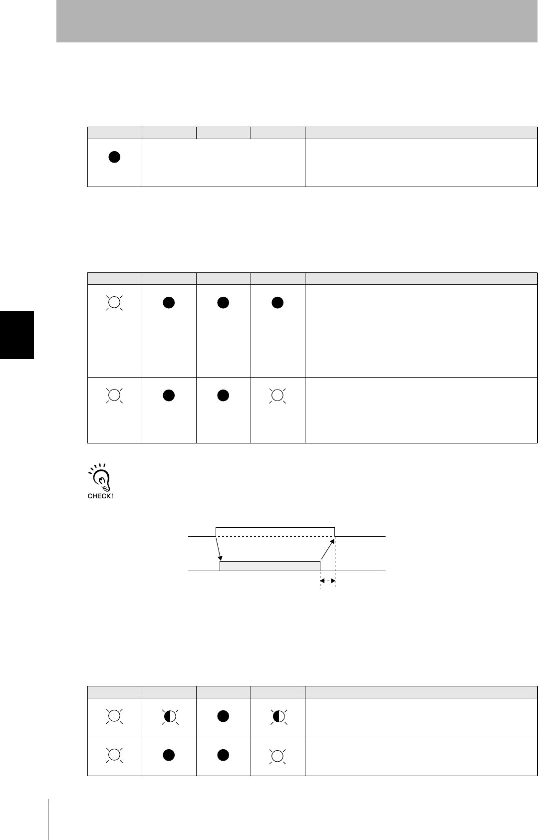
100
SECTION 5
When SECS is Not Used
CIDRW System
User’s Manual
SECTION 5
Troubleshooting
• Amplifier Unit error
Check the status of the indicator LEDs after transmission of the test command.
After taking appropriate corrective action, restart the Amplifier Unit, send the test command again and
check again.
• If there is no response to the command:
Check the status of the indicator LEDs after transmission of the test command.
After taking appropriate corrective action, restart the Amplifier Unit, send the test command again and
check again.
Method using RS signal control at the host device
In a 1:N connection using Link Units, the RS signals generated from the host device by normal control must be input as
CS signals. Turn the RS signals OFF within 15 ms after the completion of data transmission. Correct communications
will not be possible without this control.
• If there is a response to the command:
Check the status of the indicator LEDs after transmission of the test command.
After taking appropriate corrective action, restart the Amplifier Unit, send the test command again and
check again.
RUN COMM NORM ERROR Main check points
—
(If RUN is OFF, the status of the other indica-
tor LEDs can be ignored.)
• Influence of background noise (change installation position)
• Amplifier Unit power supply
If the error cannot be resolved after checking, the Amplifier Unit
may be damaged.
RUN COMM NORM ERROR Main check points
• Amplifier Unit baud rate settings
• Node numbers of the Amplifier Units (do not match the node
number in the test command)
• Connection and wiring of the cable between the host device
and Amplifier Unit
• OFF timing of the RS signals between the host device and
Amplifier Unit
• Routing of each cable (influence of background noise)
If the error cannot be resolved after checking, the Amplifier Unit
may be damaged.
• Amplifier Unit baud rate settings
• Connection and wiring of the cable between the host device
and Amplifier Unit
• Routing of the cables (influence of background noise)
• OFF timing of the RS signals between the host device and
Amplifier Unit
• FCS (frame check sequence) calculation method
RUN COMM NORM ERROR Main check points
• Node numbers of the Amplifier Units (The same number is set
for more than one unit)
If the error cannot be resolved after checking, the Amplifier
Unit may be damaged.
There is a mistake in the command format (number of charac-
ters, character code, etc.).
(Lights once)
SD at host device
RS at host device
ON only during data transmission from the host device
Within 15 ms
(Lights once)
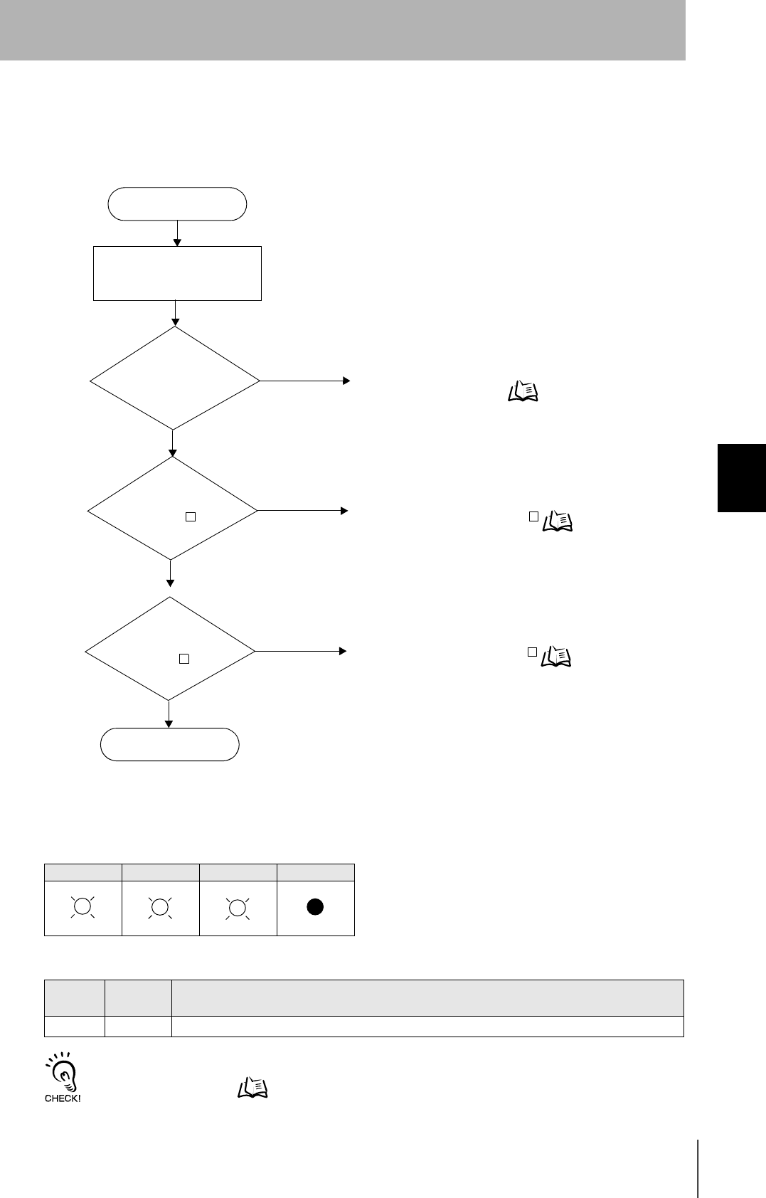
101
CIDRW System
User’s Manual
SECTION 5
When SECS is Not Used
SECTION 5
Troubleshooting
From Trial Operation to Communications
Errors are indicated by the status of the indicators after transmission of the write command, and by the
response code of the response.
• If the ID Tag was processed normally:
If there is no response to the write command, refer to the From Installation to Trial Operation,
Operation Check Flowchart. Refer to page 99.
Indicators
RUN COMM NORM ERROR
Response code for the response
Type Response
code Function
Normal 00 The ID Tag was processed normally.
Error occurrence
Is the response
code 1 ?
No
Yes Check the command format.
If the response code is 1 Refer to page 102.
Yes Communication with the ID Tag has failed.
If the response code is 7 Refer to page 102.
Write command sent
RUN-LED is OFF
No
Yes An error has occurred at the Amplifier Unit.
Amplifier Unit error Refer to page 102.
Is the response
code 7 ?
Communications OK
No
(Lights once) (Lights once)
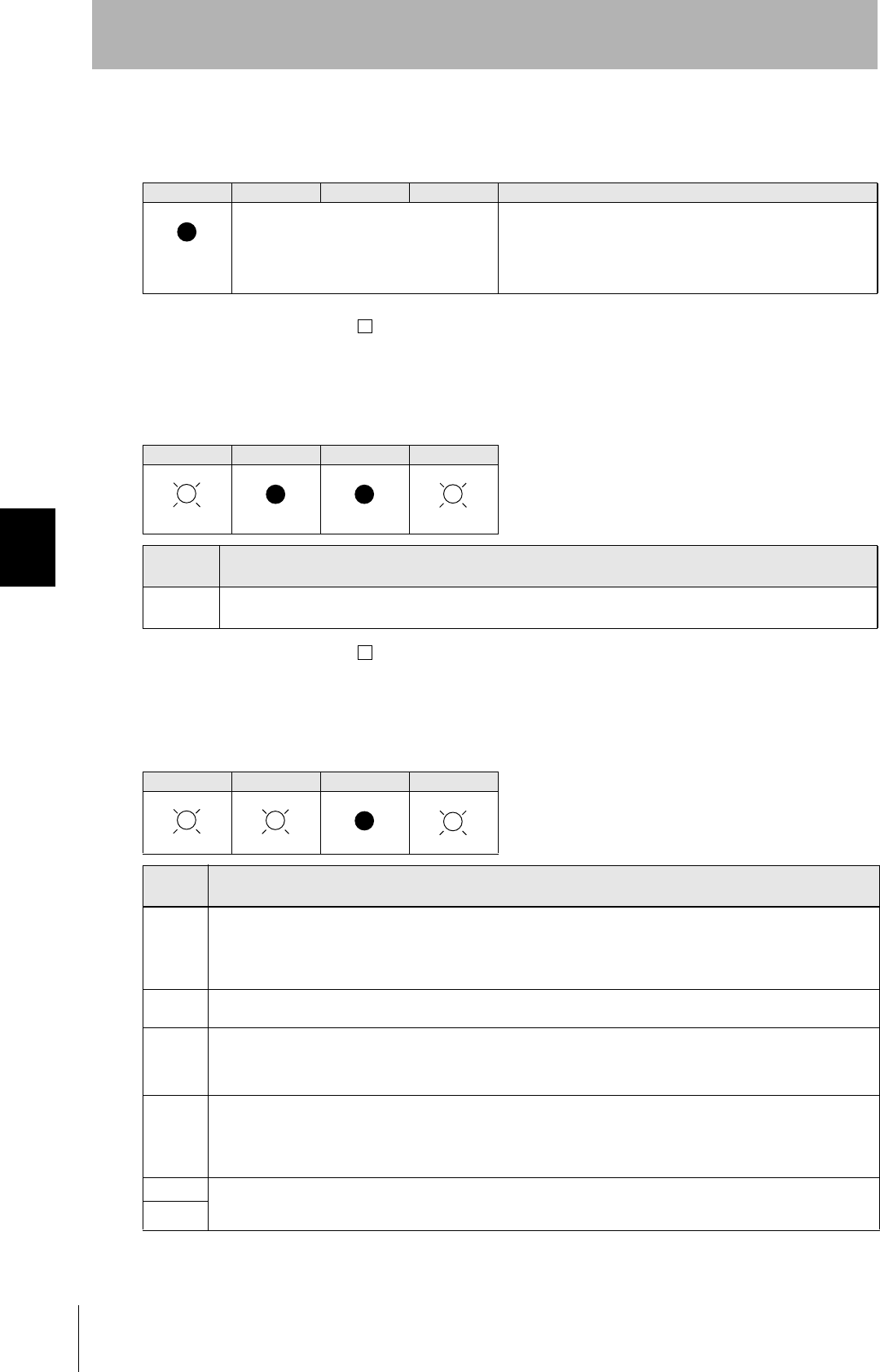
102
SECTION 5
When SECS is Not Used
CIDRW System
User’s Manual
SECTION 5
Troubleshooting
• Amplifier Unit error
Check the status of the indicator LEDs after transmission of the command.
After taking appropriate corrective action, send the write command again and check again.
• If the response code is 1 :
There is a host device communications error.
Check the status of the indicator LEDs and the response code of the response after transmission of the
command.
After taking appropriate corrective action, send the write command again and check again.
• If the response code is 7 :
There is a communications error in communication between the CIDRW Head and ID Tag.
Check the status of the indicator LEDs and the response code of the response after transmission of the
command.
After taking appropriate corrective action, send the write command again and check again.
* The ID Tag has a lock function, but the amplifier unit has no function for locking an ID Tag.
RUN COMM NORM ERROR Main check points
—
(If RUN is OFF, the status of the other indica-
tor LEDs can be ignored.)
• Influence of background noise (Change installation position)
• Amplifier Unit power supply
If the error cannot be resolved by checking the two points above,
the Amplifier Unit may be damaged.
RUN COMM NORM ERROR
Response
code Main check points
14 Command format
(Command code, page designation, address designation, processed data volume, etc.)
RUN COMM NORM ERROR
Response
code Main check points
70
• Background noise levels of the CIDRW Head (Check the surroundings with the environmental noise level measurement
function)
• Distance to another CIDRW Head
• Influence of background noise (Change installation position)
If the error cannot be resolved after checking, the Amplifier Unit may be damaged.
71 • ID Tag overwrite life (Replace the ID Tag)
• Environment of use of the ID Tags (ID Tag breakage due to use in unanticipated ways)
72 • Connection to the CIDRW Head
• Distance between the ID Tag and CIDRW Head
• CIDRW Head background noise levels (Check the surroundings with the environmental noise level measurement function)
• Distance to another CIDRW Head
7B • Distance between the ID Tag and CIDRW Head
• Background noise levels of the CIDRW Head (Check the surroundings with the environmental noise level measurement
function)
• Distance to another CIDRW Head
• Influence of background noise (Change installation position)
7E • Type/specifications of the ID Tags used
• Settings of the ID Tags used (The ID Tag lock function is used.*)
• Environment of use of the ID Tags (ID Tag breakage due to use in unanticipated ways)
7F
(Lights once)
(Lights once) (Lights once)

SECTION 6
Appendix
103
CIDRW System
User’s Manual
SECTION 6
Appendix
Specifications and Dimensions 104
System Configuration Examples 108
When SECS is Not Used 109
Characteristic Data depending on Conditions of Use 110
Data Segment Area 122
Regular Inspection 123
SECS Protocol Specifications 124
ASCII Code Table 129
Protective Construction 130
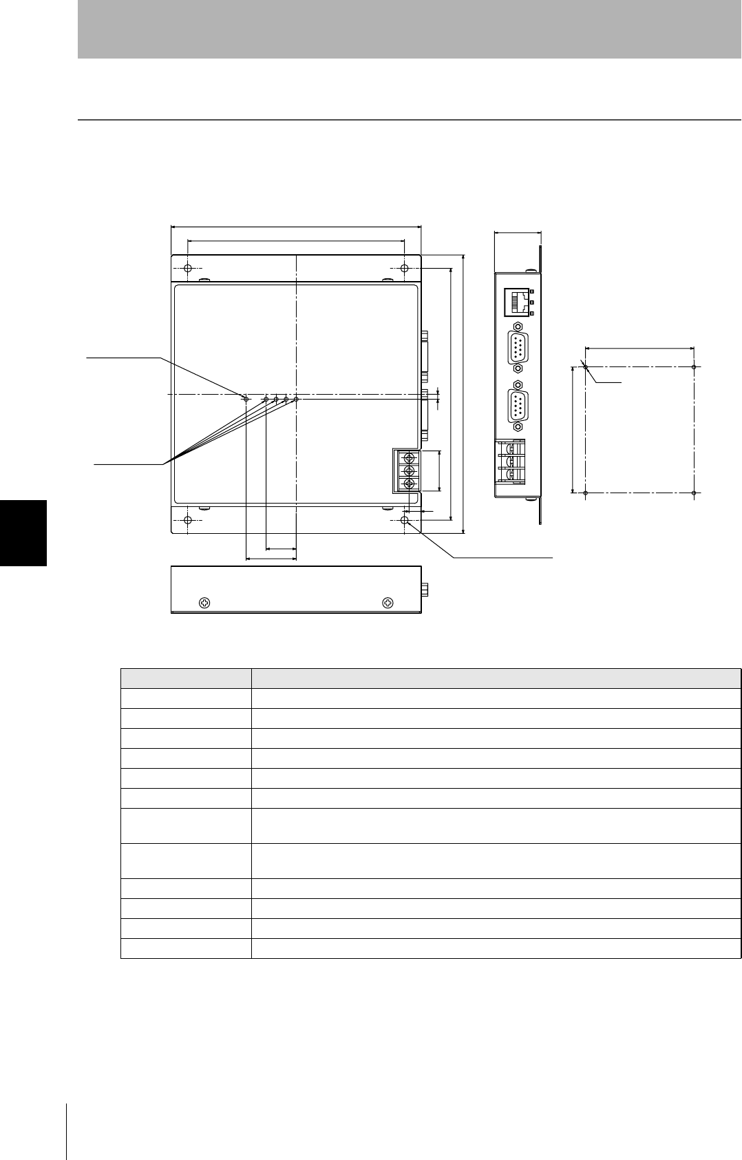
104
SECTION 6
Specifications and Dimensions
CIDRW System
User’s Manual
SECTION 6
Appendix
Specifications and Dimensions
Controller
V700-L22
Item Specifications
Power supply voltage 24 VDC +10% -15%
Current consumption 150 mA max. (inrush current: approx. 10 A max.)
Ambient temperature Operating: 0 to +40°C Storage: -15 to +65°C (with no icing)
Ambient humidity Operating: 10 to 85% RH Storage: 10 to 95% RH (with no condensation)
Degree of protection IP20 (IEC60529)
Insulation resistance 50 MΩ min. between power supply terminals and the frame ground terminal (500 VDC M)
Dielectric strength Leak current not to exceed 3.5 mA on application of 500 VAC (50/60 Hz for 1 minute) between both
power supply terminals and the frame ground terminal
Vibration resistance Frequency: 10 to 150 Hz; double amplitude: 0.20 mm; acceleration: 15 m/s2 for
8 minutes, 10 times each in X, Y, and Z directions
Shock resistance Shock of 150 m/s2 in X, Y, and Z directions, 3 times each for 18 repetitions
Ground Ground to 100 Ω or less.
Case material SECC (coating)
Weight Approx. 570 g
2:
r
r
/
Ǿ
(Unit: mm)
Mounting dimensions
Power indicator
Indicators
(mounting holes)
Four, 4.5-dia. holes
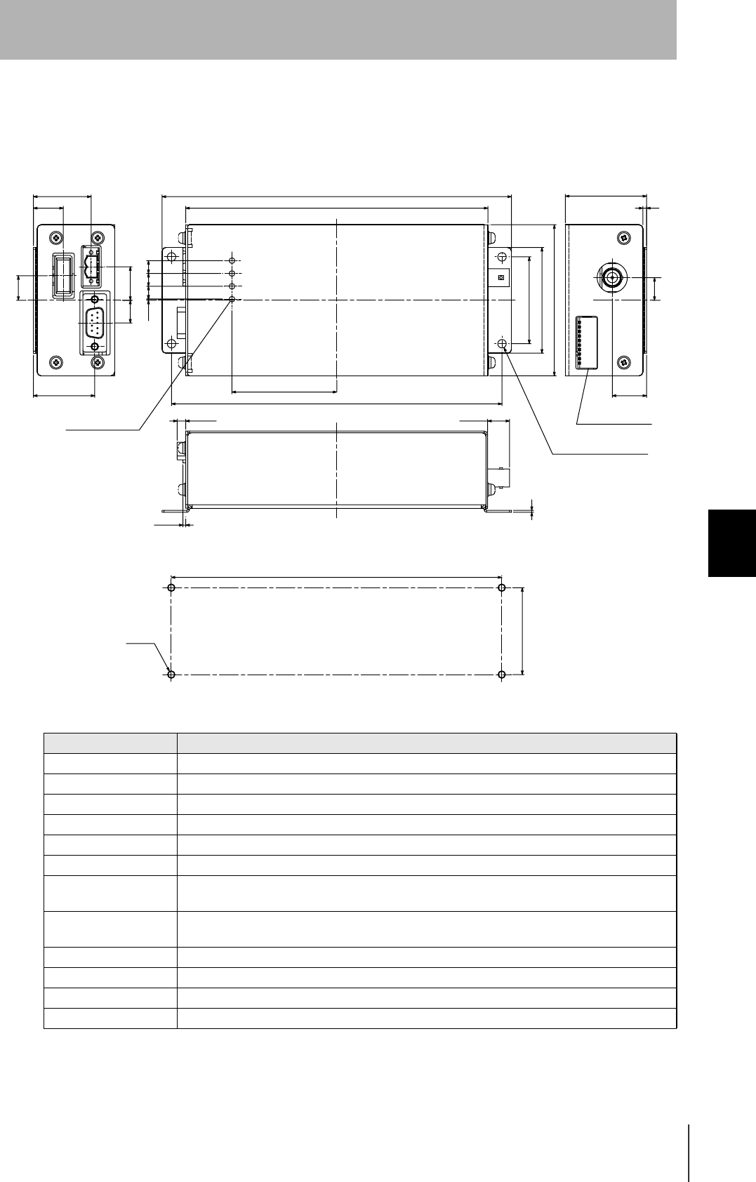
CIDRW System
User’s Manual
SECTION 6
Specifications and Dimensions
SECTION 6
Appendix
105
Amplifier Unit
V640-HAM11
Item Specifications
Power supply voltage 24 VDC +10% -15%
Current consumption 150 mA max.
Ambient temperature Operating: 0 to +40°C Storage: -15 to +65°C (with no icing)
Ambient humidity Operating/Storage: 35 to 85% RH (with no condensation)
Degree of protection IP20 (IEC60529 standard)
Insulation resistance 20 MΩ min. between power supply terminals and the frame ground terminal (100 VDC M)
Dielectric strength Leak current not to exceed 5 mA on application of 1000 VAC (50/60 Hz for 1 minute) between both
power supply terminals and the frame ground terminal
Vibration resistance Frequency: 10 to 150 Hz; double amplitude: 0.20 mm; acceleration: 15 m/s2 for
8 minutes, 10 times each in X, Y, and Z directions
Shock resistance Shock of 150 m/s2 in X, Y, and Z directions, 3 times each for 18 repetitions
Ground Ground to 100 Ω or less.
Case material SECC (coating)
Weight Approx. 500 g
㧔㧕
㧔㧕
㧔㧕
㧔㧕
㧔㧕
㧔㧕
㧔㧕
㧔㧕
㧔㧕
r
r
Ǿ
/
DIP switch
(Unit: mm)
Mounting dimensions
4 indicators
Four, 4.5-dia. holes
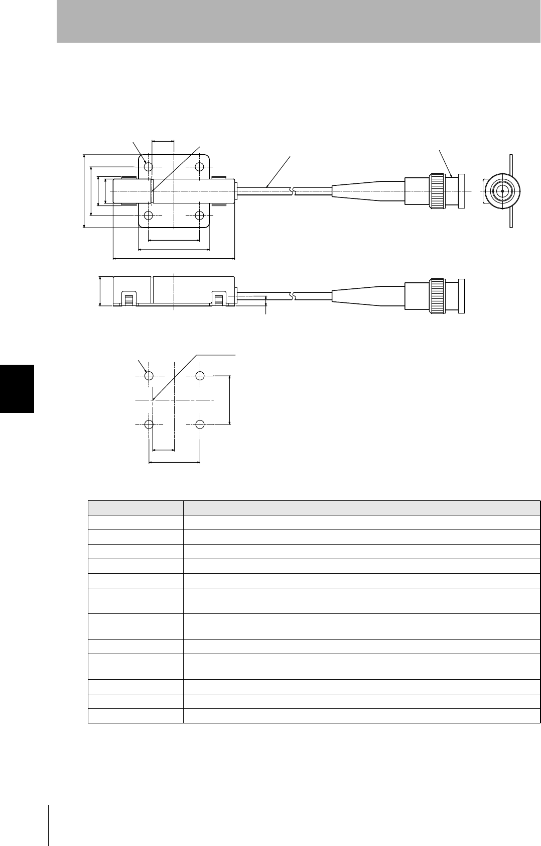
106
SECTION 6
Specifications and Dimensions
CIDRW System
User’s Manual
SECTION 6
Appendix
CIDRW Head
V640-HS61
Item Specifications
Transmission frequency 134 kHz
Ambient temperature Operating: 0 to +40°C Storage: -15 to +65°C (with no icing)
Ambient humidity Operating/Storage: 35 to 85% RH (with no condensation)
Degree of protection IP60 (IEC60529)
Insulation resistance 20 MΩ min. between all terminals and the case (100 VDC M)
Dielectric strength Leak current not to exceed 5 mA on application of 1000 VAC (50/60 Hz for 1 minute) between all
terminals and the case
Vibration resistance Frequency: 10 to 150 Hz; double amplitude: 0.20 mm; acceleration: 15 m/s2 for
8 minutes, 10 times each in X, Y, and Z directions
Shock resistance Shock of 150 m/s2 in X, Y, and Z directions, 3 times each for 18 repetitions
Casing material ABS/epoxy resin
Stainless steel mount
Weight Approx. 70 g
Cable length 2 m
Cable specification 3-mm-dia. coaxial cable
r
r
Ǿ
/14Ǿ
Coaxial cable 3.0 dia., standard length 2 m
(Unit: mm)
Connector
Antenna center
Antenna center
Mounting dimensions
Four M3 or 3.5-dia. holes
Four, 3.5-dia. holes
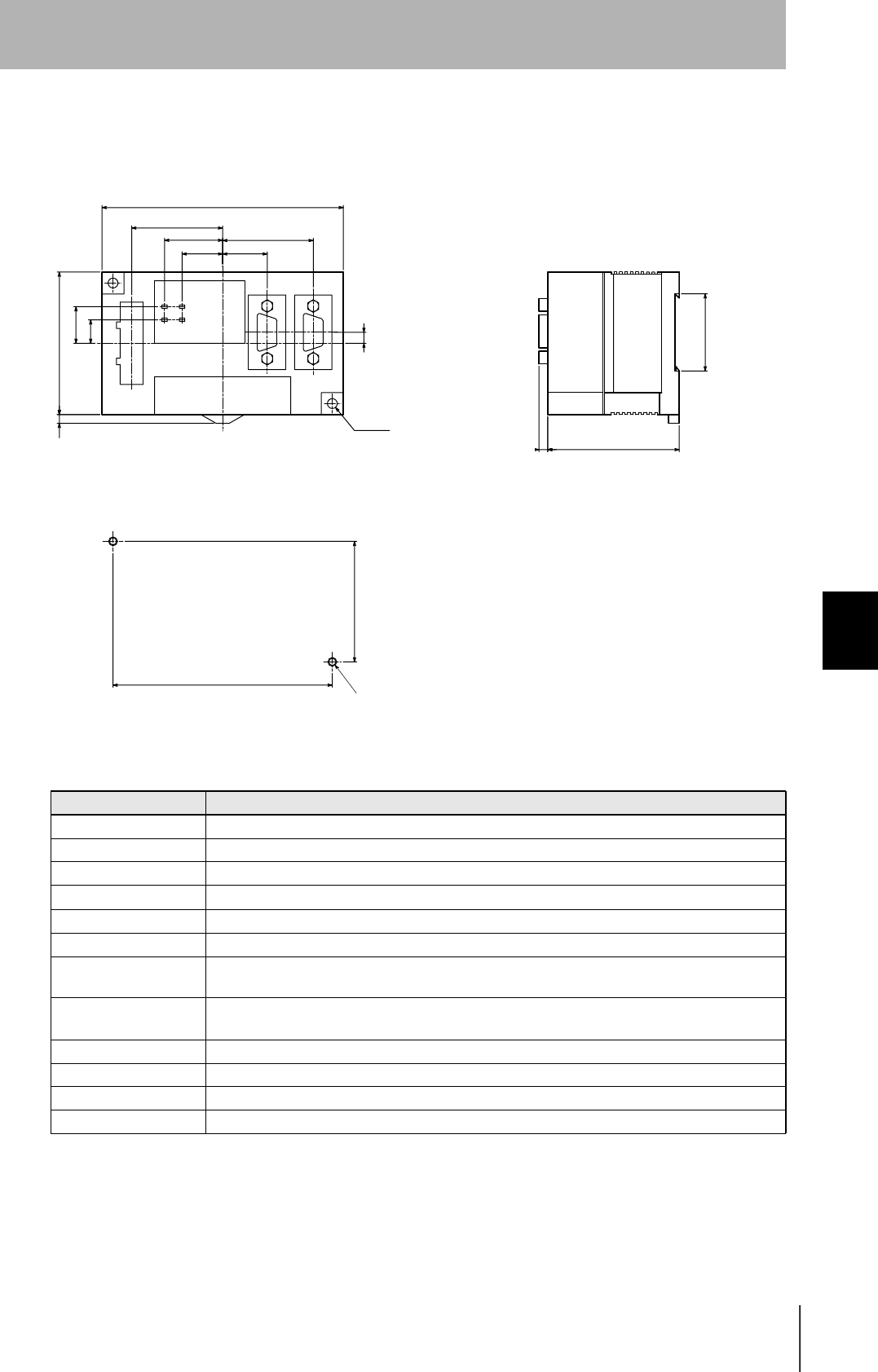
CIDRW System
User’s Manual
SECTION 6
Specifications and Dimensions
SECTION 6
Appendix
107
Link Unit
V700-L11
Item Specifications
Power supply voltage 24 VDC +10% -15%
Current consumption 250 mA max. (inrush current: approx. 10 A)
Ambient temperature Operating: 0 to +40°C Storage: -15 to +50°C (with no icing)
Ambient humidity Operating/Storage: 35 to 85% RH (with no condensation)
Degree of protection IP20 (IEC60529)
Insulation resistance 50 MΩ min. between power supply terminals and the frame ground terminal (500 VDC M)
Dielectric strength Leak current not to exceed 5 mA on application of 1000 VAC (50/60 Hz for 1 minute) between
power supply terminals and the frame ground terminal
Vibration resistance Frequency: 10 to 150 Hz; double amplitude: 0.20 mm; acceleration: 15 m/s2 for 8 minutes, 10 times
each in X, Y, and Z directions
Shock resistance Shock of 150 m/s2 in X, Y, and Z directions, 3 times each for 18 repetitions
Ground Ground to 100 Ω or less.
Case material PC/ABS resin
Weight Approx. 200 g
r
r
Ǿ
/ޓ14ޓǾ
(Unit: mm)
Mounting dimensions
Two M4 or 4.2-dia. holes
Two, 4.5-dia. holes

118
SECTION 6
Characteristic Data depending on Conditions of Use
CIDRW System
User’s Manual
SECTION 6
Appendix
Communications Time
Regardless of whether SECS is used or not, take the time required for processing between the host
device and Amplifier Units into account when designing the system.
Communication time calculation formula (unit: ms)
Read: 150.5 × (number of pages) + 6.1
For write, same writing: 468.6 × (number of pages) + 80.3
Byte write: 468.6 × (number of pages/8) + 229.9
TAT calculation formula (units: ms)
TAT = command and response transmission time + communication time
The command and response transmission time differs depending on the number of characters
sent and the communications conditions.
This calculation applies to continuous transmission in which the Controller uses no spaces
between command characters.
Example of TAT calculation:
Number of command characters: A; number of response characters: B
Baud rate: 9600 bps, data length: 8 bits, non parity, 1 stop bit
Time Description
Communications time This is the time required for communication between an ID Tag and the CIDRW Head.
TAT This is the time required for processing at the Amplifier Unit, seen from the host device.
Host
Amplifier Unit
Command Response
Communications time
TAT
Rounding up
Transmission time (ms) = Number of bits per character (bits)
Baud rate (bps) × total number of characters of command and response
TAT (ms) = 10
9600 × (A + B) + Communications time (ms)
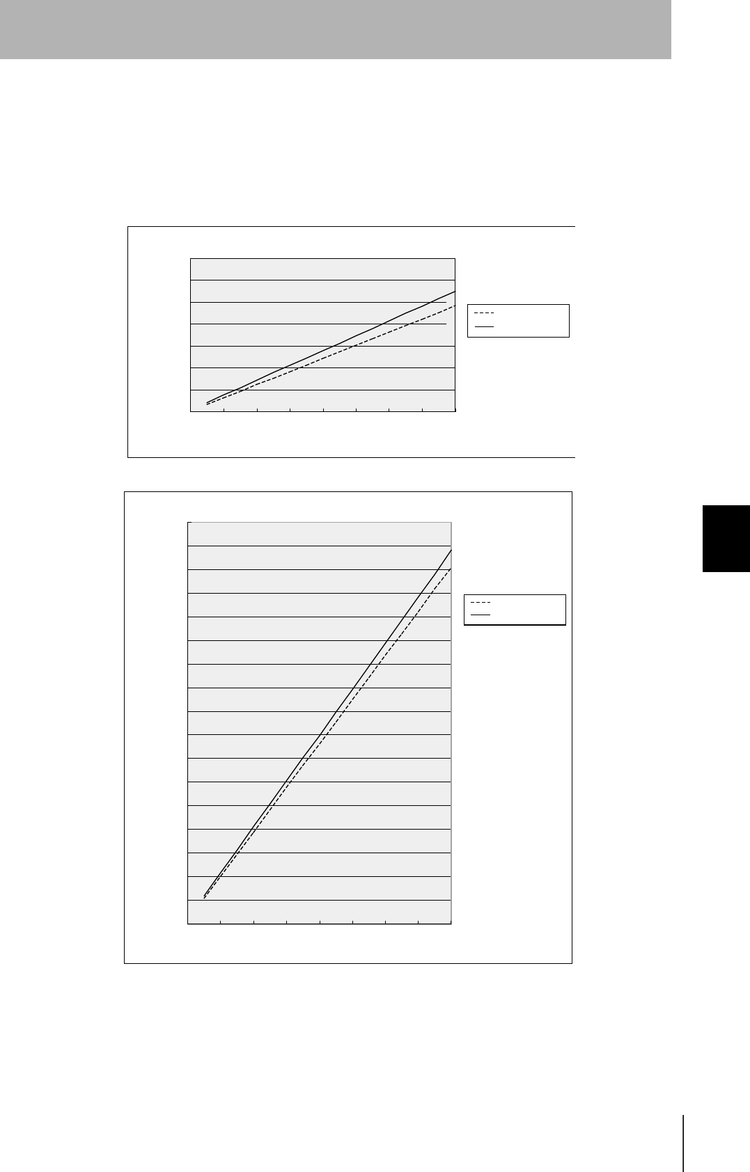
CIDRW System
User’s Manual
SECTION 6
Characteristic Data depending on Conditions of Use
SECTION 6
Appendix
119
The graph for communications time for communication between the ID Tag and CIDRW Head, and
TAT (when the baud rate is 9600 bps), is shown below.
Note however that the communications time and TAT may increase substantially according to the con-
ditions of use.
㪇
㪌㪇㪇
㪈㪇㪇㪇
㪈㪌㪇㪇
㪉㪇㪇㪇
㪉㪌㪇㪇
㪊㪇㪇㪇
㪊㪌㪇㪇
㪈㪉㪋㪍㪏㪈㪇㪈㪉㪈㪋㪈㪍
Read
Number of pages processed
Communications time
TAT (9600 bps)
Communications time (ms)
Communications time (ms)
Write (same writing)
Number of pages processed
Communications time
TAT (9600 bps)
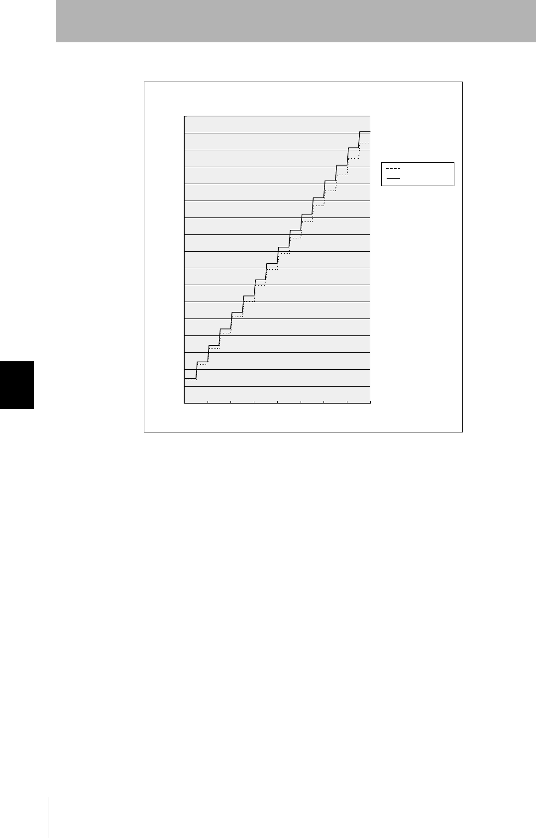
120
SECTION 6
Characteristic Data depending on Conditions of Use
CIDRW System
User’s Manual
SECTION 6
Appendix
Communications time (ms)
Byte Write
Number of bytes processed
Communications time
TAT (9600 bps)
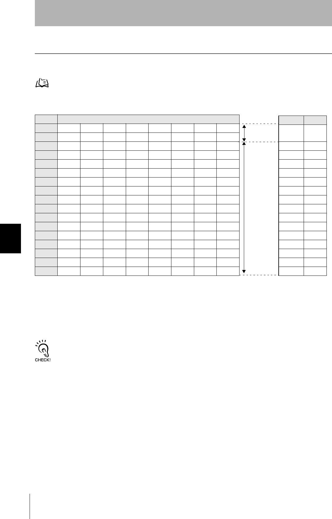
122
SECTION 6
Data Segment Area
CIDRW System
User’s Manual
SECTION 6
Appendix
Data Segment Area
The data segment area of the RI-TRP-DR2B ID Tag is shown below.
When using a CIDRW Controller, always set the data segment.
Refer to page 53.
• The carrier ID memory area starts from page 1 (fixed).
• 00h to 87h in the table are addresses.
Page 8 bytes/1 page
1 00h 01h 02h 03h 04h 05h 06h 07h
2 08h 09h 0Ah 0Bh 0Ch 0Dh 0Eh 0Fh
3 10h 11h 12h 13h 14h 15h 16h 17h
4 18h 19h 1Ah 1Bh 1Ch 1Dh 1Eh 1Fh
5 20h 21h ••• ••• 27h
6 28h 29h ••• ••• 2Fh
7 30h 31h ••• ••• 37h
8
9 :
10 : :
11 :
12
13
14 68h 69h ••• ••• 6Fh
15 70h 71h ••• ••• 77h
16 78h 79h ••• ••• 7Fh
17 80h 81h ••• ••• 87h
DATASEG LENGTH
Carrier
ID
16
"S01" 8
"S02" 8
"S03" 8
"S04" 8
"S05" 8
"S06" 8
"S07" 8
"S08" 8
"S09" 8
"S10" 8
"S11" 8
"S12" 8
"S13" 8
"S14" 8
"S15" 8
Carrier ID
(16 byte)
Data area
(Total of 120
bytes)
Data segment area Example of data
segment settings

CIDRW System
User’s Manual
SECTION 6
Regular Inspection
SECTION 6
Appendix
123
Regular Inspection
In order to maintain optimum performance of the functions of the CIDRW system, daily and periodic
inspections are necessary.
Inspection item Detail Criteria Tools required
Supply voltage fluctuation Check that the supply voltage fluctuation
at the power supply terminal block is
within the permissible range.
To be within supply voltage rating. Multimeter
Check that there are no frequent instan-
taneous power failures or radical voltage
drops.
To be within permissible voltage fluctua-
tion range.
Power supply
analyzer
Environment Ambient tem-
perature
Check that the ambient temperature and
humidity are within specified range.
To be within the specified range. Maximum and
minimum ther-
mometer
Hygrometer
Ambient
humidity
Vibration and
shock
Check that no vibration or shock is trans-
mitted from any machines.
Dust Check that the system is free of dust
accumulation.
To be none.
Corrosive gas Check that no metal part of the system is
discolored or corroded.
I/O power
supply
Voltage fluctu-
ation
Check on the I/O terminal block that the
voltage fluctuation and ripple are within
the permissible ranges.
To be within the specified range. Multimeter
Oscilloscope
Ripple
Mounting condition Check that each device is securely
mounted.
There must be no loose screws. —
Check that each connector is securely
connected.
Each connector must be locked or
securely tightened with screws.
Check that no screw of the terminal
block is loosened.
There must be no loose screws.
Check that no wire is broken or nearly
broken.
There must be no wire that is broken or
nearly broken.
Check if grounding to 100 Ω or less has
been done.
To be grounded to 100 Ω or less.

124
SECTION 6
SECS Protocol Specifications
CIDRW System
User’s Manual
SECTION 6
Appendix
SECS Protocol Specifications
A summary of the SEMI standards that relate to CIDRW is provided for reference when using this product.
However, since the SEMI standards are subject to revision, you should also refer to the actual standards.
• SEMI E99 THE CARRIER ID READER/WRITER FUNCTIONAL STANDARD
• SEMI E5 EQUIPMENT COMMUNICATION STANDARD 2 MESSAGE CONTENT (SECS II)
• SEMI E4 EQUIPMENT COMMUNICATION STANDARD 1 MESSAGE TRANSFER (SECS I)
Operation Model
Set the CIDRW Controller's mode switch to "0" and start the system. When the system starts, the ini-
tial processing is completed first, then the system will operate according to the status defined by E99.
CIDRW status model
Operational status OPERATING Operation in progress in the operating mode
IDLE Status in which no processing is in progress at any head
BUSY Status when processing is in progress at any of the heads
MAINTENANCE Operation in progress in the maintenance mode
# Transitions according to state changes from the host device
Alarm status No alarm Status in which there are no alarms currently in effect at the CIDRW Controller
or any of the connected heads
ALARM Status in which an alarm has occurred
• If a head in an abnormal status is detected during head detection in initial
processing, or no heads are detected. (The error will not be cleared until the
system has been restarted with the heads connected correctly.)
• When a head error is detected in communications with an ID Tag. (The error
will be automatically reset if it is cleared in subsequent processing.)
• A CIDRW Controller internal error has occurred.
Initial status
(INITIALIZING)
This is the status during processing such as internal initialization/head detection after startup, which is
maintained until the CIDRW system is capable of its proper functions.
CIDRW Head status model
Operational status OPERATING Status in which the head is operating normally
IDLE Status in which no processing is in progress
BUSY Status in which processing is in progress
NON-OPERATING Status in which a head check (CIDRW Head, Link Unit) is necessary
(The CIDRW alarm status is the ALARM status.)

CIDRW System
User’s Manual
SECTION 6
SECS Protocol Specifications
SECTION 6
Appendix
125
Protocol Specifications
• Character composition
Start bit (1) + data bits (8) + stop bit (1)
* Conforms to SEMI E4
• Protocol parameters
• Double block detection
The header of the block currently being received is compared with the correct block received immedi-
ately before, and double blocks are detected. A setting in the setting mode determines whether this
function is used or not.
•Multi-block
Multi-blocks are supported at the receiving side (maximum of 128 blocks).
Multi-blocks are used at the sending side.
• Message size
The maximum receivable message size is 32 kbytes.
• Interleaving
The receiving side supports interleaving and block interleaving.
The sending side uses interleaving and block interleaving.
The maximum number of simultaneously open transactions is 16. If the maximum number is
exceeded, SxF0 (abort transmission) is sent.
• Device ID
The number of device IDs used is 1. Device IDs are specified in the setting mode.
• Block numbers
With a single block, the block number is either 1 or 0. For multi-block transmission, the numbers 1 to
128 are used. The block number for a single block is set in the setting mode.
• Treatment of the systems byte
The system byte comprises the source ID and the transaction ID.
The source ID is a fixed value and is specified in the setting mode.
The initial value of the transaction ID is 1 and the maximum value is 0xFFFF. The value is incremented
from the first message transmission.
Sign Name Default setting Setting range Setting
unit
BAUD Baud Rate 9600 1200, 2400, 4800, 9600, 19200, 38400, 57600, 115200 -
DEVID Device ID 0 0 to 32767 1
T1 Time-out between characters 0.5 s 0.1 to 10 s 0.1 s
T2 Protocol time-out 10 s 0.2 to 25 s 0.2 s
T3 Response time-out 45 s 1 to 120 s 1 s
T4 Time-out between blocks 45 s 1 to 120 s 1 s
RTY Retry limit 3 0 to 31 1
M/S Master/slave M M : Master
S : Slave
-

126
SECTION 6
SECS Protocol Specifications
CIDRW System
User’s Manual
SECTION 6
Appendix
•Storing
The method for storing in the BUSY status, e.g. because the internal buffer is full, is to use "NAK trans-
mission."
• Processing for time-out detection
At T3 and T4 time-outs, the time-out is notified by the S9F9 message.
• SECS parameters
Item Default setting Range Setting Unit
Double block detection yes/no 1 1: The header of the block currently being received is
compared with the correct block received immediately
before, and double blocks are detected.
0: Double block detection is not performed.
-
Source ID 0 0 to 32767 1
Single block No. 1 0, 1 -

CIDRW System
User’s Manual
SECTION 6
SECS Protocol Specifications
SECTION 6
Appendix
127
Support Attributes
CIDRW attribute definitions
Attribute names Description Access Re-
quest Format and mounting
Basic items "Configuration" Number of CIDRW Heads RO Y 20 "00"-"31"
The number of heads connected
when the system power is turned
ON (automatic recognition)
"AlarmStatus" Substate of current CIDRW
alarms
RO Y 20
"0" = no alarm
"0" = alarm has occurred
"OperationalStatus" Substate of current CIDRW
operations
RO Y 20
"IDLE"
"BUSY"
"MANT"
"SoftwareRevisionLevel" Software revision (version) RO Y 20 6byte
"VVV.RR"
(VVV = version, RR = revision)
CarrierIDOffset The position of the offset,
referenced to the first byte
of the carrier ID in the tag.
RW N 20 00-15
However, (CarrierIDOffset +
CarrierIDLength) ≤ 16.
CarrierIDlength The number of bytes in the
carrier ID (if there are any
non-visible ASCII charac-
ters in the carrier ID, the
CIDRW returns an error to
the host controller.
RW N 20 01-16
However, (CarrierIDOffset +
CarrierIDLength) ≤ 16.
Option "DateInstalled Date on which the sub-
system was installed
RW N 20 8 bytes
All " " (space) on shipping
"DeviceType" CIDR / CIDRW classifica-
tion
RO N 20 5 bytes
"CIDRW"
"HardwareRevisionLevel" Hardware revision number RO N 20 6 bytes
"VVV.RR"
(VVV = version, RR = revision)
"MaintenanceData" Supplier dependent RW N 20 80 bytes
All " " (space) on shipping
"Manufacturer" Manufacturer's name or ID RO N 20 17 bytes
"OMRON Corporation"
"ModelNumber" Model name according to
the maker
RO N 20 6 bytes
"L22 "
"SerialNumber" System serial number RO N 20 max. 20 bytes
(Not supported by the CIDRW)

128
SECTION 6
SECS Protocol Specifications
CIDRW System
User’s Manual
SECTION 6
Appendix
Reader/writer head attribute definition
Attribute names Description Access Re-
quest Format and mounting
Basic items "HeadStatus" Current status RO Y 20
"IDLE"
"BUSY"
"NOOP"
"HeadID" Head number 1 to 31 RO Y
(multi)
20
"01"-"31"
("00" indicates the CIDRW itself,
so cannot be used.)
Option "Cycles" Number of read/write oper-
ations executed
RO N 54 (unsigned 4-byte integer)
(Not supported by the Reader/
Writer Head)
"HeadCondition" Maintenance status RO N 20
"NO": No alarm
"NM": Status in which normal
operation is not possible
and maintenance is neces-
sary
"RW": Read/write error
"RT": Read/write error rate
(Not supported by the
Reader/Writer Head)
"NP": Status of power supply and
connection errors
"HeadDateInstalled" Date on which the head
was installed
RO N 20 "YYYYMMDD"
(Not supported by the Reader/
Writer Head)
"HeadMaintenanceData" Supplier dependent N N 20
(Not supported by the Reader/
Writer Head)
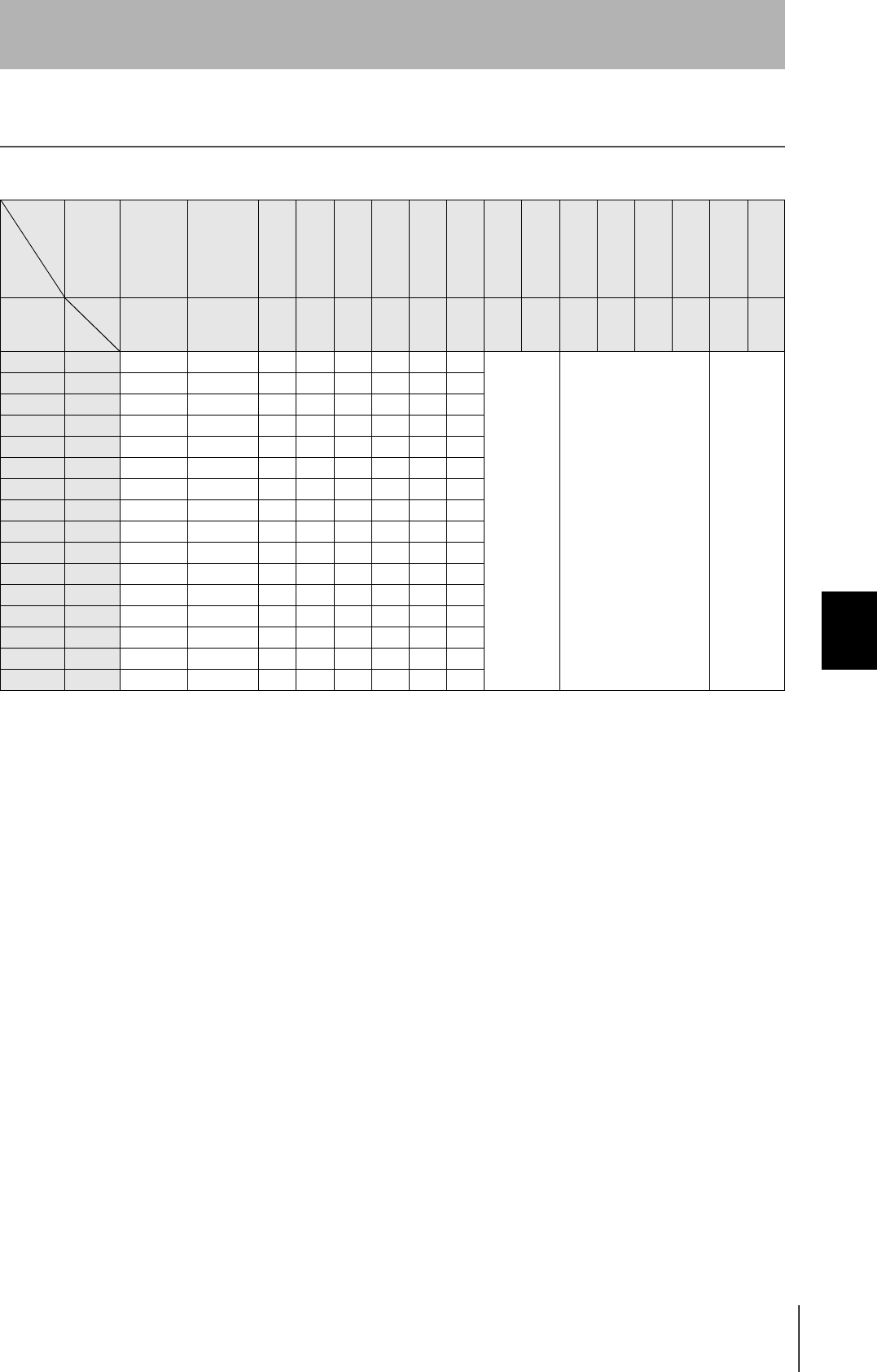
CIDRW System
User’s Manual
SECTION 6
ASCII Code Table
SECTION 6
Appendix
129
ASCII Code Table
Leftmost
bits
Right-
most bits
b8 - b5
0000 1001 0010 0011 0100 0101 0110 0111 1000 1101 1010 1011 1100 1101 1110 1111
b4 - b1
Row
Line
0 1
2345678910 11 12 13 14 15
0000 0
NUL TC7(DLE)
(SP) 0 @ P ` p
Undefined Undefined Undefined
0001 1
TC1(SOH) DC
1
!1AQaq
0010 2
TC2(STX) DC
2
"2BRbr
0011 3
TC3(ETX) DC
3
#3CScs
0100 4
TC4(EOT) DC
4
$4DTdt
0101 5
TC5(NEQ) TC
8
(NAK)
%5EUeu
0110 6
TC6(ACK) TC
9
(SYN)
&6FVf v
0111 7
BEL TC
10
(ETB)
'7GWgw
1000 5
FE0(BS) CAN
(8HXhx
1001 9
FE1(HT) EM
)9IYiy
1010 10
FE2(LF) SUB
*:JZjz
1011 11
FE3(VT) ESC
+;K[k{
1100 12
FE4(FF) IS
4
(FS)
,<L\ l |
1101 13
FE5(CR) IS
3
(GS)
-=M]m}
1110 14
S0 IS
2
(RS)
.>N^nÅP
1111 15
S1 IS
1
(US)
/?O_oDEL
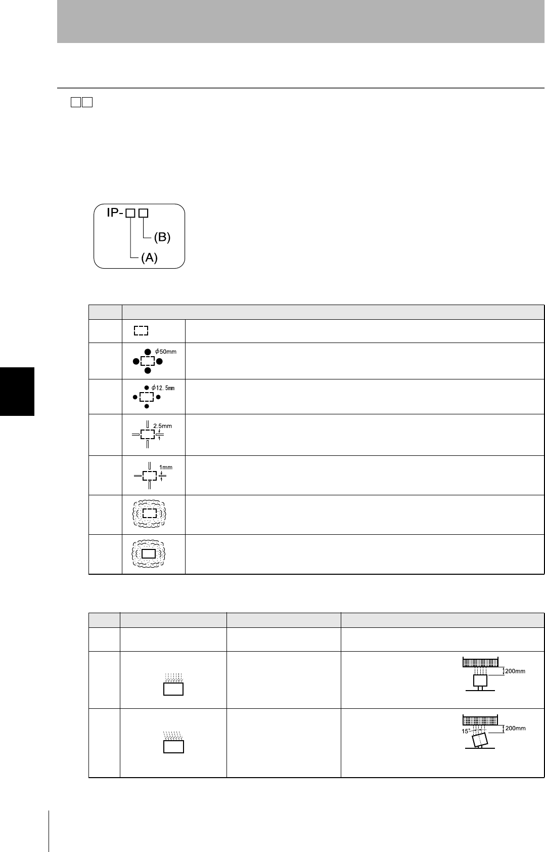
130
SECTION 6
Protective Construction
CIDRW System
User’s Manual
SECTION 6
Appendix
Protective Construction
IP- is governed by the test methods described below. Check in advance the seal characteristics under
the actual environment and conditions of use.
IP is the abbreviation of International Protection.
IEC (International Electrotechnical Commission)
Standard (IEC60529: 1989-11)
(A) First numeral in code: Class of protection against entry of solid foreign material
(B) Second numeral of code: Class of protection against the entry of water
Class Degree of protection
0 No protection
1 Protected against access by solid objects with a diameter of 50 mm or greater (e.g. human hands).
2 Protected against access by solid objects with a diameter of 12.5 mm or greater (e.g. fingers).
3 Protected against access by wires and solid bodies with a diameter of 2.5 mm or greater.
4 Protected against access by wires and solid bodies with a diameter of 1 mm or greater.
5 Entry of volumes of dust that would cause difficulties in normal operation of devices or compromise
safety is prevented.
6 Entry of dust is prevented.
Class Degree of protection Outline of test methods (tests using water)
0 No special protection No protection against the
entry of water. No test
1 Protection against droplets
of water The product suffers no ill
effects from droplets of water
falling vertically onto it.
Water droplets are
sprayed onto the product
from directly above for 10
minutes by water droplet
exposure test apparatus.
2 Protection against droplets
of water The product suffers no ill
effects from droplets of water
directed at it at an angle of up
to 15° to vertical.
The water droplet expo-
sure test apparatus is set
to 15° from vertical and
water droplets sprayed
onto the product for 10
minutes (total of 2.5 min-
utes in each direction).
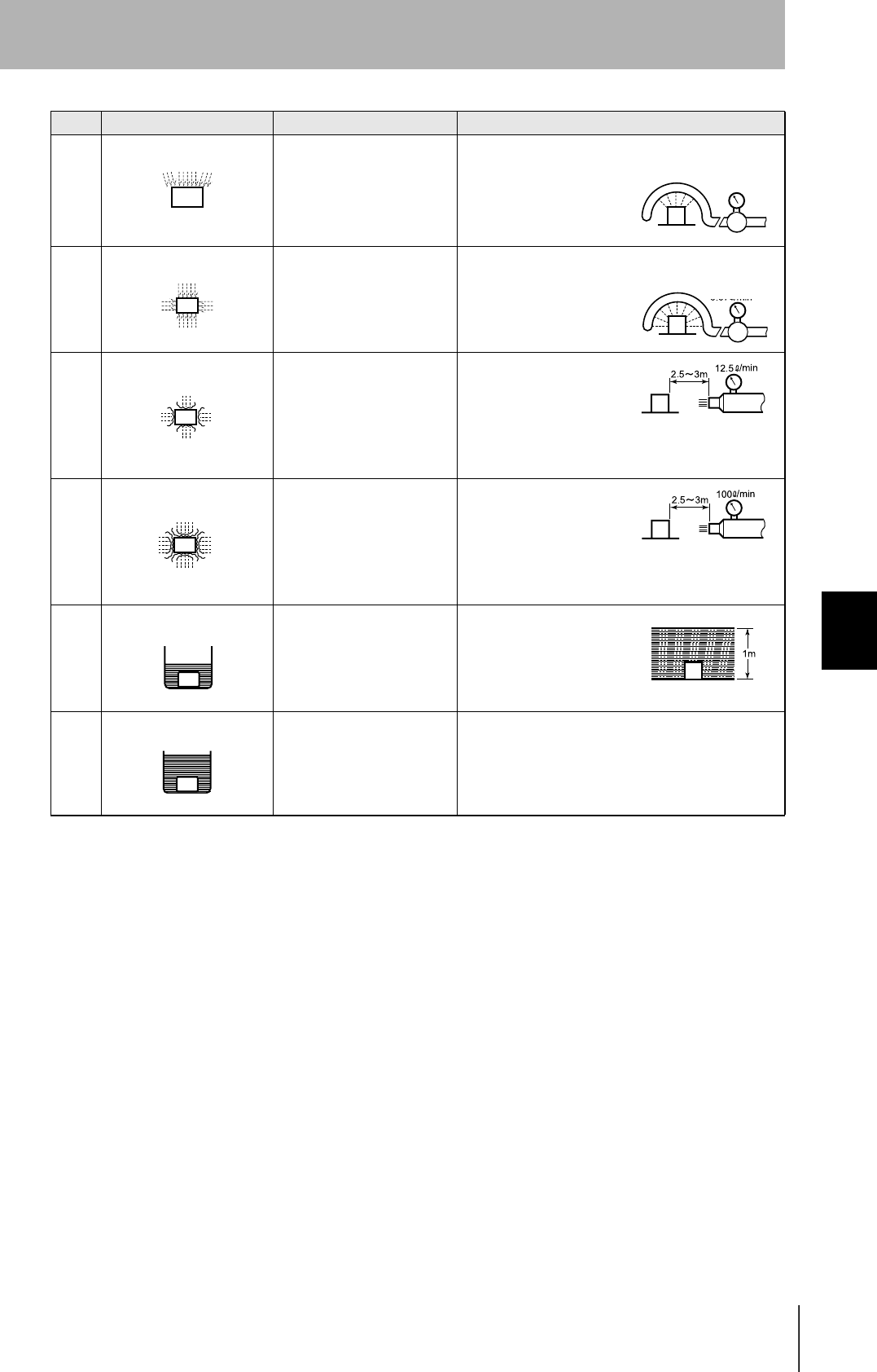
CIDRW System
User’s Manual
SECTION 6
Protective Construction
SECTION 6
Appendix
131
3 Protection against spraying
water The product suffers no ill
effects from a water spray
directed at it at up to 60° from
vertical.
Using the test apparatus
shown in the figure to the
right, water is sprayed
from both directions, onto
both sides of the product,
at angles up to 60° from
vertical for 10 minutes.
4 Protection against splashing
water The product suffers no ill
effects from water splashed
on it from all directions.
Using the test apparatus
shown in the figure to the
right, water is splashed
onto the product from all
directions for 10 minutes.
5 Protection against water
jets The product suffers no ill
effects from a water jet aimed
directly at it from all directions.
Using the test apparatus
shown in the figure to the
right, a water jet is directed
at the product from all
directions for 1 minute per
square meter of outer cas-
ing, with a minimum total
exposure of 3 minutes.
6 Protection against powerful
jets of water Water does not enter the
product when a powerful jet of
water is directed at it from all
directions.
Using the test apparatus
shown in the figure to the
right, a water jet is directed
at the product from all
directions for 1 minute per
square meter of outer cas-
ing, with a minimum total
exposure of 3 minutes.
7 Protection against immer-
sion in water No entry of water on
immersion in water at the
stipulated pressure for the
stipulated time.
Immerse in water for 30
minutes at a depth of 1
meter (when the height of
the apparatus is less than
850 mm).
8 Protection against
immersion in water The product can be used
while continually immersed in
water.
Depends on arrange-
ments made between the
manufacturer and the user
of the product.
Class Degree of protection Outline of test methods (tests using water)
0.07 L/min.
per hole in the
spray nozzle
0.07 L/min.
per hole in the
spray nozzle
Diameter of spray
nozzle head: φ6.3
Diameter of spray
nozzle head: φ12.5

132
SECTION 6
Index
CIDRW System
User’s Manual
SECTION 6
Appendix
Index
A
Amplifier Unit 27, 34
Amplifier Unit Indicators 98
Amplifier Unit V640-HAM11 20
ASCII Code Table 129
B
Byte Write 87
C
Change the data segment area 53
Change the response time-out time 56
Changing the Position of the Mode Switch
on the Bottom of the Unit 48
Characteristic Data depending on
Conditions of Use 109
CIDRW Controller 26, 31
CIDRW Controller V700-L21 19
CIDRW Head 28
CIDRW Head V640-HS61 21
CIDRW Systems that Conform to
SEMI Standards (SEMI E99, E5, E4) 17
Coaxial Mounting 110, 111
Command 82
Command/Response Format 81
Communications Distance
Characteristics vs. Ambient Noise 121
Communications Test 65
Communications Time 118
Component Names and Functions 19
Connections and Wiring 31
Connector for connecting a CIDRW Head 34
Controller Indicators 92
E
Data Reading and Writing 28
Data Segment Area 122
G
Features 17
Flowchart for Getting Started 23
For Coaxial Installation 116
For Face-to-Face Installation 116
For Parallel Installation 116
From Installation to Trial Operation 99
From Trial Operation to Communications 101
H
Host Connection Port 42
I
ID Tag ↔ CIDRW System
Communications Test 66
IEC (International Electrotechnical
Commission) Standard (IEC605291989-11) 130
Influence of Background Metal on ID Tag 29
Influence of Background Metals
(Reference Only) 117
Influence of Noise 29
Installation 26
L
Link Unit 30, 41
Link unit V700-L11 22
List of Error Messages 92, 98
M
Maps of Communications Areas
(Reference Only) 110
Message Specifications 70
Mounting 29
Multi-connection port 45
Mutual Interference Distances
(Reference Only) 116
N
NAK 89
Noise measurement 89
Normal Operation Mode 93
O
Operation Check Flowchart 93, 99
Operation Model 124
P
Parallel Mounting 112, 113
Positional Relationship between
the CIDRW Head and the ID Tag 28
Power Supply 41
Power Supply and Grounding Wires 31, 34
Protective Construction 130
Protocol Specifications 125

CIDRW System
User’s Manual
SECTION 6
Index
SECTION 6
Appendix
133
Index
R
READ 83
Regular Inspection 123
RESET 89
Return to the Normal Operation mode 58
RS-232C Port 36
RS-485 Port 39
S
Same Write 86
SECS port 32
SECS Protocol Specifications 124
Sending a Switching Command
from the Host Device 49
Set the Communications Conditions
for Amplifier Units 61
Set the Communications Conditions
for Link Units 63
Set the Communications Conditions
for the CIDRW Controller 48
Set the parameters for
the communications conditions 50
Setting Mode 96
Specifications and Dimensions 104
Specifications for Each Stream/Function 72
Start the terminal software 49
Support Attributes 127
Switch to the Setting mode 48
System Configuration 18
T
TEST 88
Test for Communications with the Host Device 65
V
Vertical Mounting 114, 115
W
What is a CIDRW System? 16
When SECS is Not Used 65, 68, 81, 98
When SECS is Used 18, 65, 66, 70, 92
When the Mode is Selected by
a Command Sent from the Host Device 58
When the Mode is Selected with
the Mode Switch on the Bottom of the Unit 58
WRITE 84