Omron 6CYCIDV6700101 Radio Frequency Identification System User Manual Manual
Omron Corporation Radio Frequency Identification System Manual
UserManual.wiki
>
Omron
>
6CYCIDV6700101 User Manual
>
Manual
Contents
1.
Manual2
2.
Manual
Manual
Navigation menu
Upload a User Manual
Namespaces
Wiki Guide
HTML
PDF
Info
Views
User Manual
Discussion / Help
Navigation


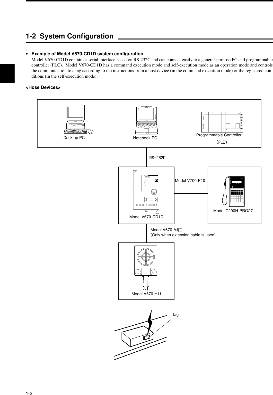
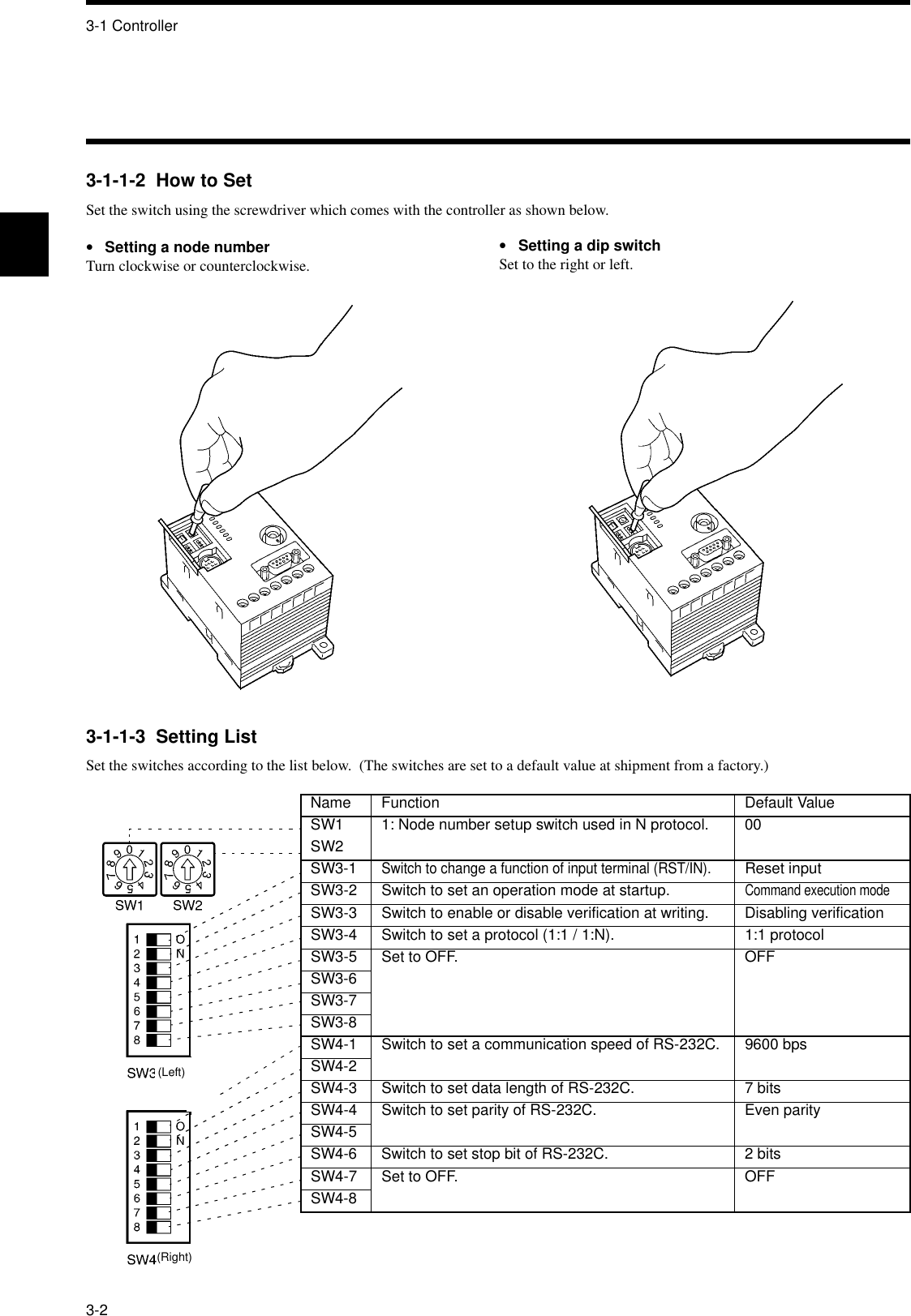
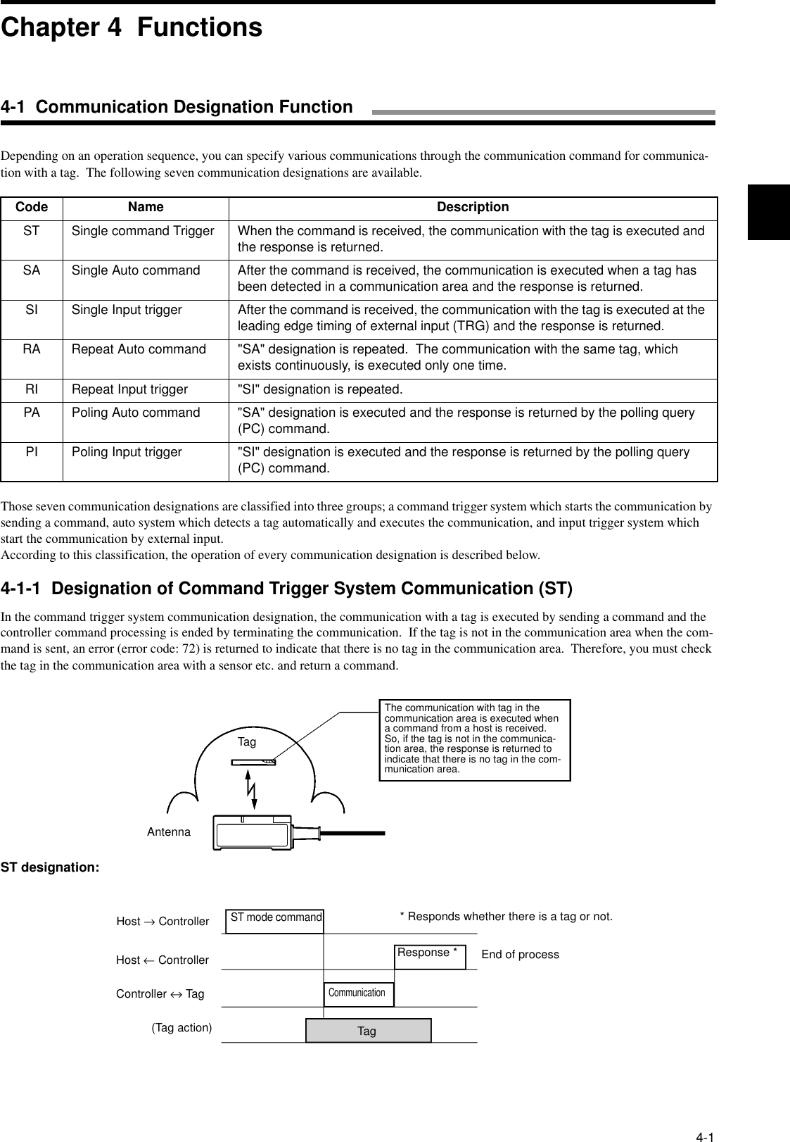
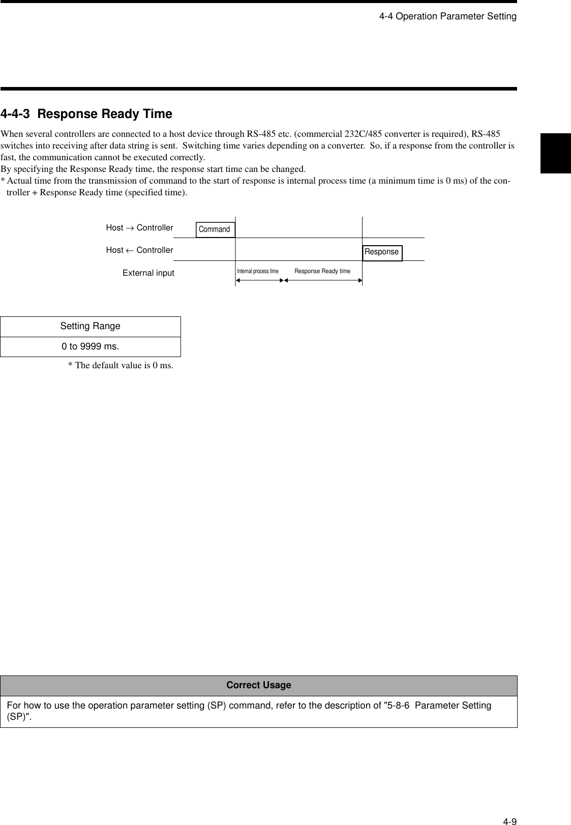

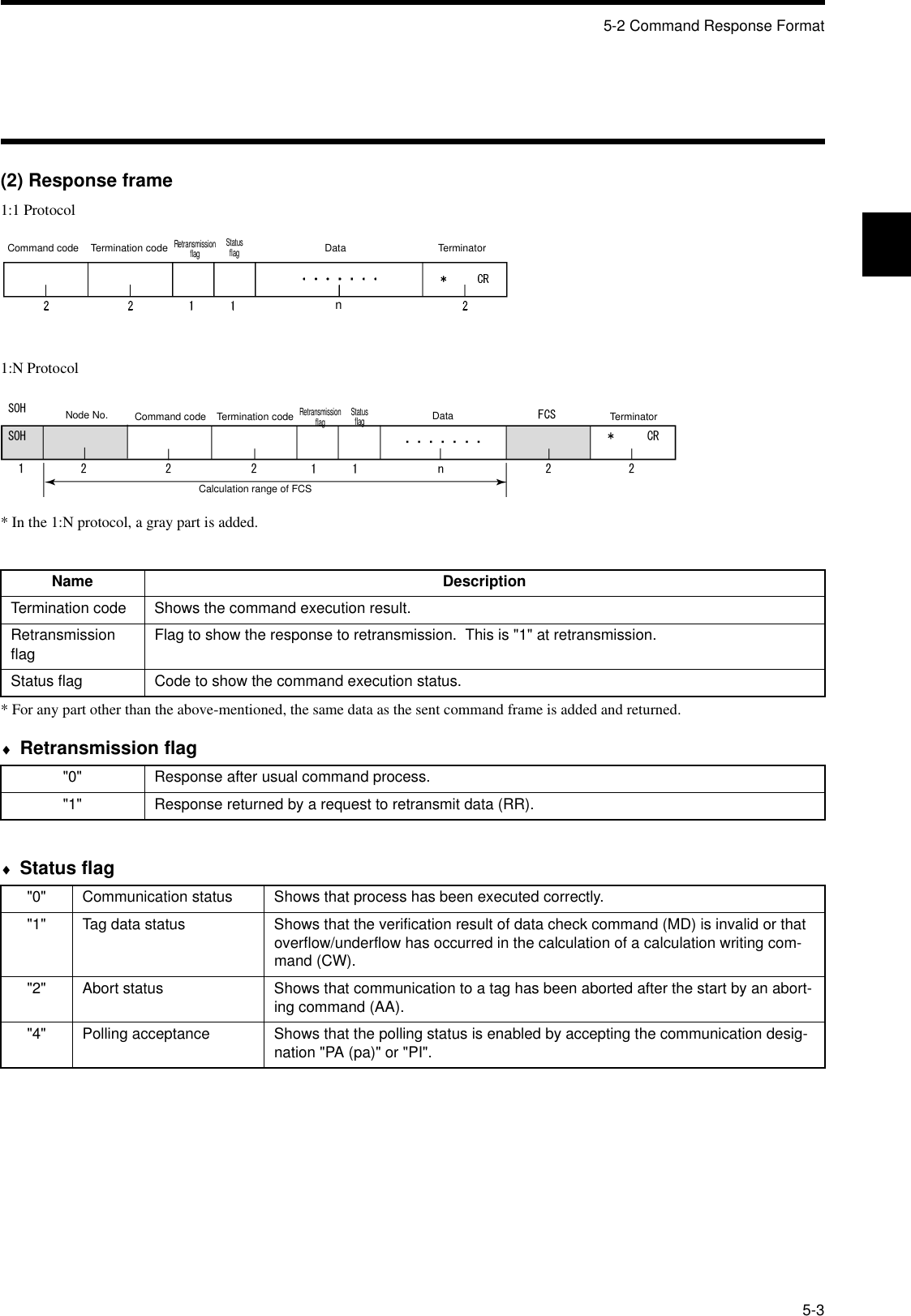
![5-2 Command Response Format5-4(3) Data code designationYou can specify in a command a code to be used to transmit a data to be read or written between a host device and ID controller. ASCII code designation and hexadecimal code designation are available.•ASCII code (JIS8 unit code) designation "A"1 Byte of data in a tag is transmitted directly as ASCII code or JIS8 unit code. Transmitted one character is equivalent to 1 byte of data in a tag. Character data can be read/written directly. However, do not use any control code [SOH] nor [CR] in a data to be transmitted. If [SOH] or [CR] is specified in a written data, a command error occurs.<Example of writing>If you specify "OMRON" as a written data in 5 bytes of memory beginning with the address 10h, the data is written in memory in a tag as shown in this figure.<Example of writing>•Hexadecimal code designation "H"1 Byte of data in a tag is converted into two hexadecimal characters ("00" to "FF") and transmitted. Transmitted two character is equiv-alent to 1 byte of data in a tag. Be sure to specify a written data with every two characters "00" to "FF" (even number). If any data of odd number of characters is specified, a command error occurs.<Example of writing>If you specify "1234" as a written data in 2 bytes of memory beginning with the address 20h, the data is written in memory in a tag as shown in this figure.<Example of reading>If you read 2 bytes of memory beginning with the address 20h, the read data is "1234" in the data shown in this figure.<Command>CommandCommunication designation ASCII designation Antenna designationFirst address Number of bytes Written dataCommandTermination codeRead dataRetransmis-sion flag StatusflagMemory in tagAddressIf you read 5 bytes of memory beginning with the address 10h, the read data is "OMRON" in the data shown in this figure.<Command>CommandCommunication designation ASCII designation Antenna designationFirst address Number of bytesWritten dataMemory in tagAddress<Response>CommandTermination codeRead dataRetransmis-sion flag Statusflag](https://usermanual.wiki/Omron/6CYCIDV6700101.Manual/User-Guide-153970-Page-58.png)
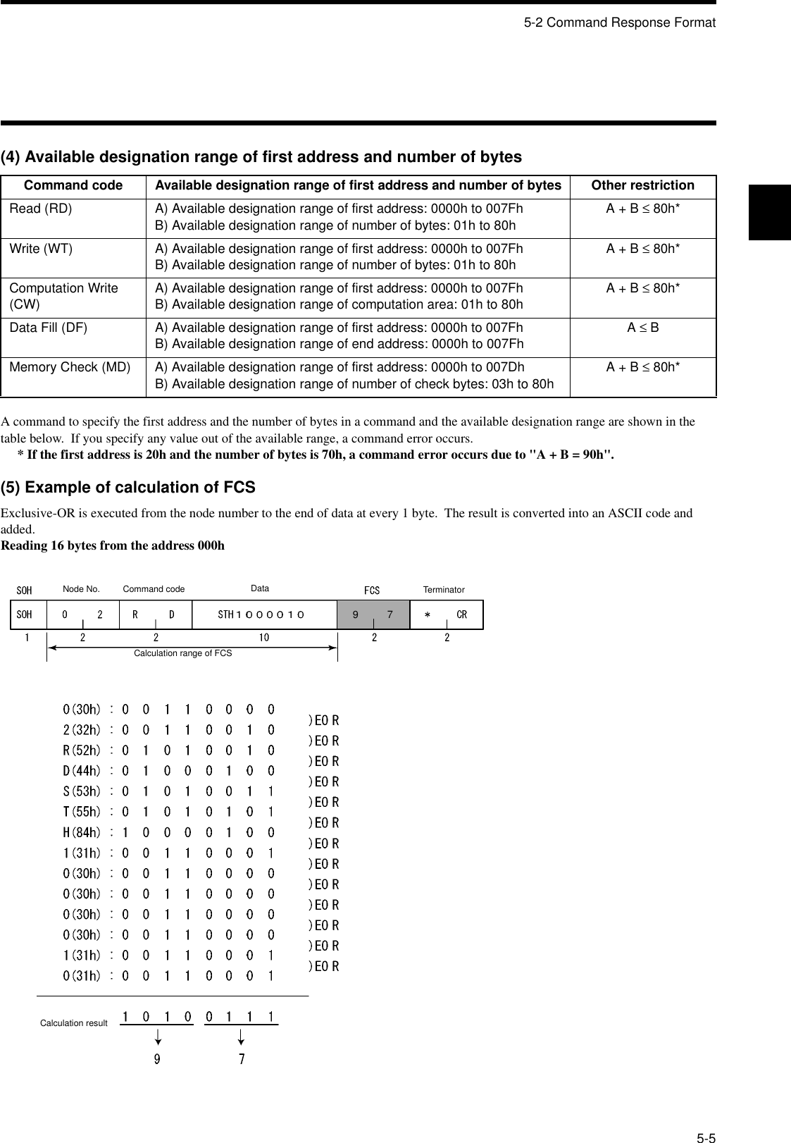
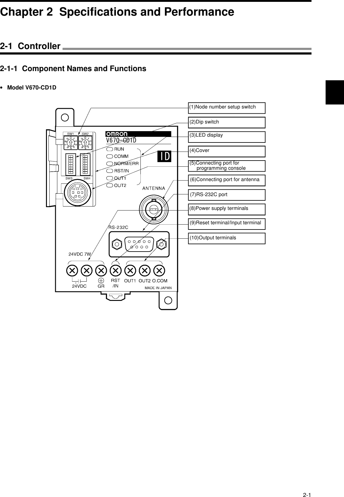
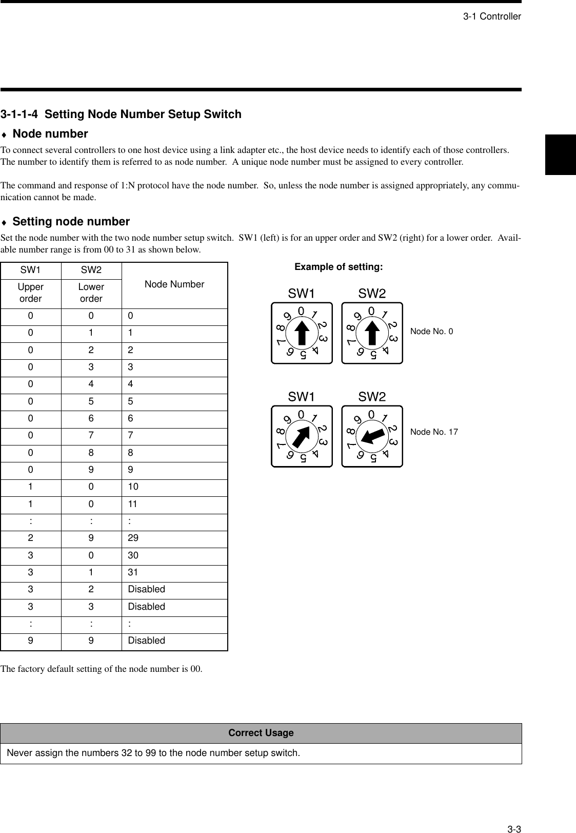
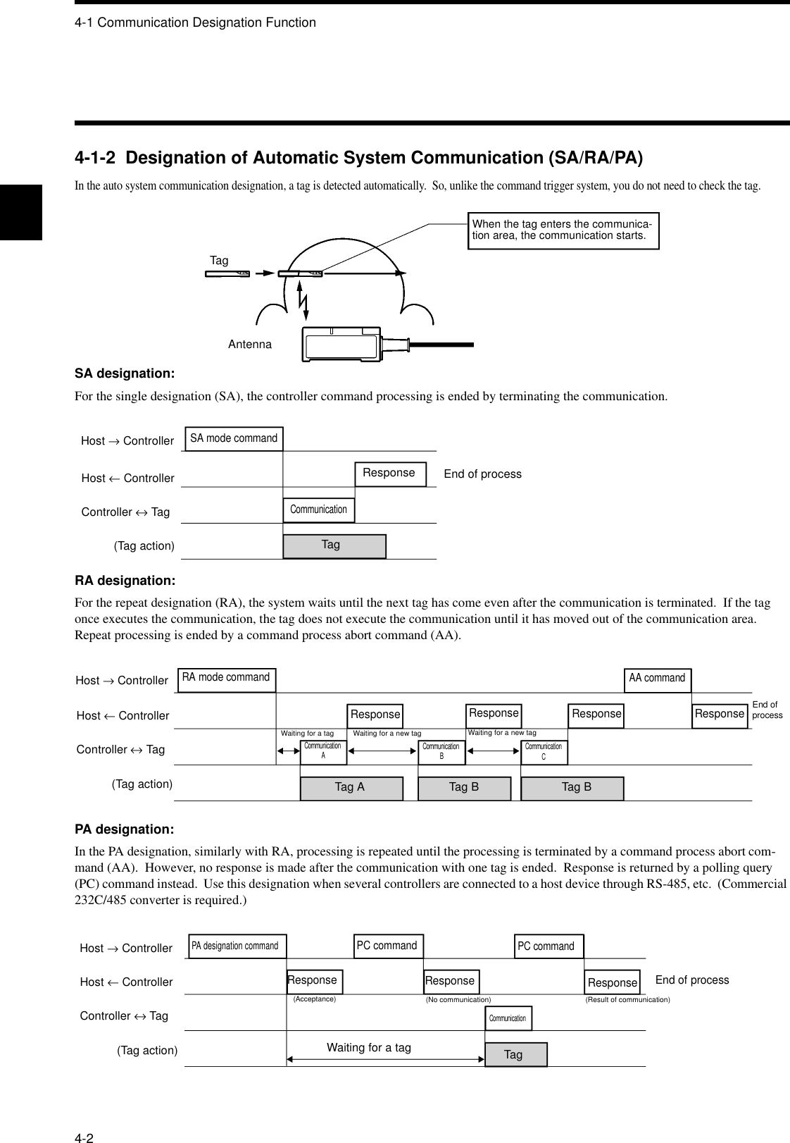
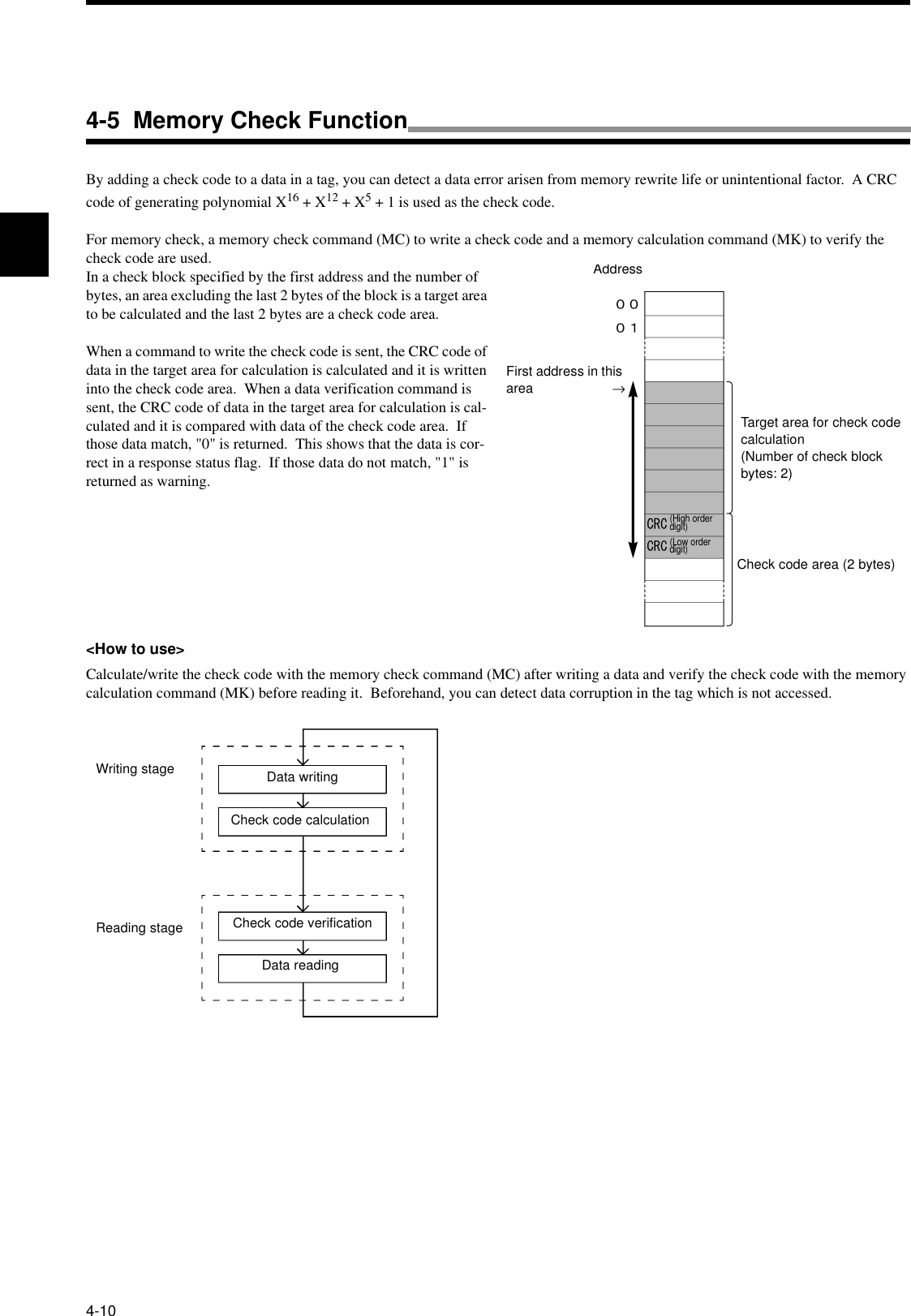
![5-6 Communication Command5-105-6-1 Read (RD)Reads a data in a area specified by the first address and the number of bytes.Example: Reading 8 bytes of data from the address 0000h(Single trigger, hexadecimal code)Sent data: RDSTH 1 0 0 0 0 0 8 * [CR]Received data: RD 0 0 0 0 1 2 3 4 5 6 7 8 1 2 3 4 5 6 7 8 * [CR]Communication designation Specifies how to communicate with a tag. For details, refer to the communication designation list.Data designation Specifies a type of transmitted code of read data at the response."A": ASCII code"H": Hexadecimal codeAntenna designation Fixed to "1".First address of read area Specifies the first address of area, where data is read from a tag, in four hexadecimal digits.Available designation range: 0000h to 007Fh.Number of read bytes Specifies the number of bytes of data read from a tag in two hexadecimal digits. A max-imum of 256 characters can be read at a time.Available designation range: 01h to 80h.Read data Data read from a tag. For the ASCII code, the number of characters is the number of read bytes. For the hexadecimal code, the number of characters is the number of read bytes x 2.Correct UsageSpecify the number of read bytes so that the sum of the number of read bytes and the first address of read area cannot exceed the tag memory capacity (128 bytes).Example: For the address 0010h, the range between 00h and 70h can be specified.<Command>Command code"RD"Communication designationDatadesig-nationAntenna designa-tionFirst address of read area Number of read bytes<Response>Command code"RD"Termination code"00"Retrans-mission flagStatus flag Read dataNumber of specified bytes](https://usermanual.wiki/Omron/6CYCIDV6700101.Manual/User-Guide-153970-Page-64.png)
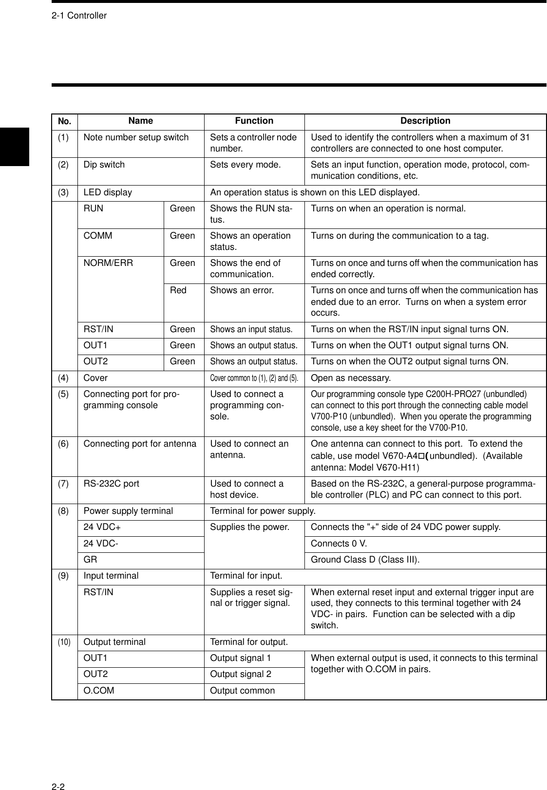
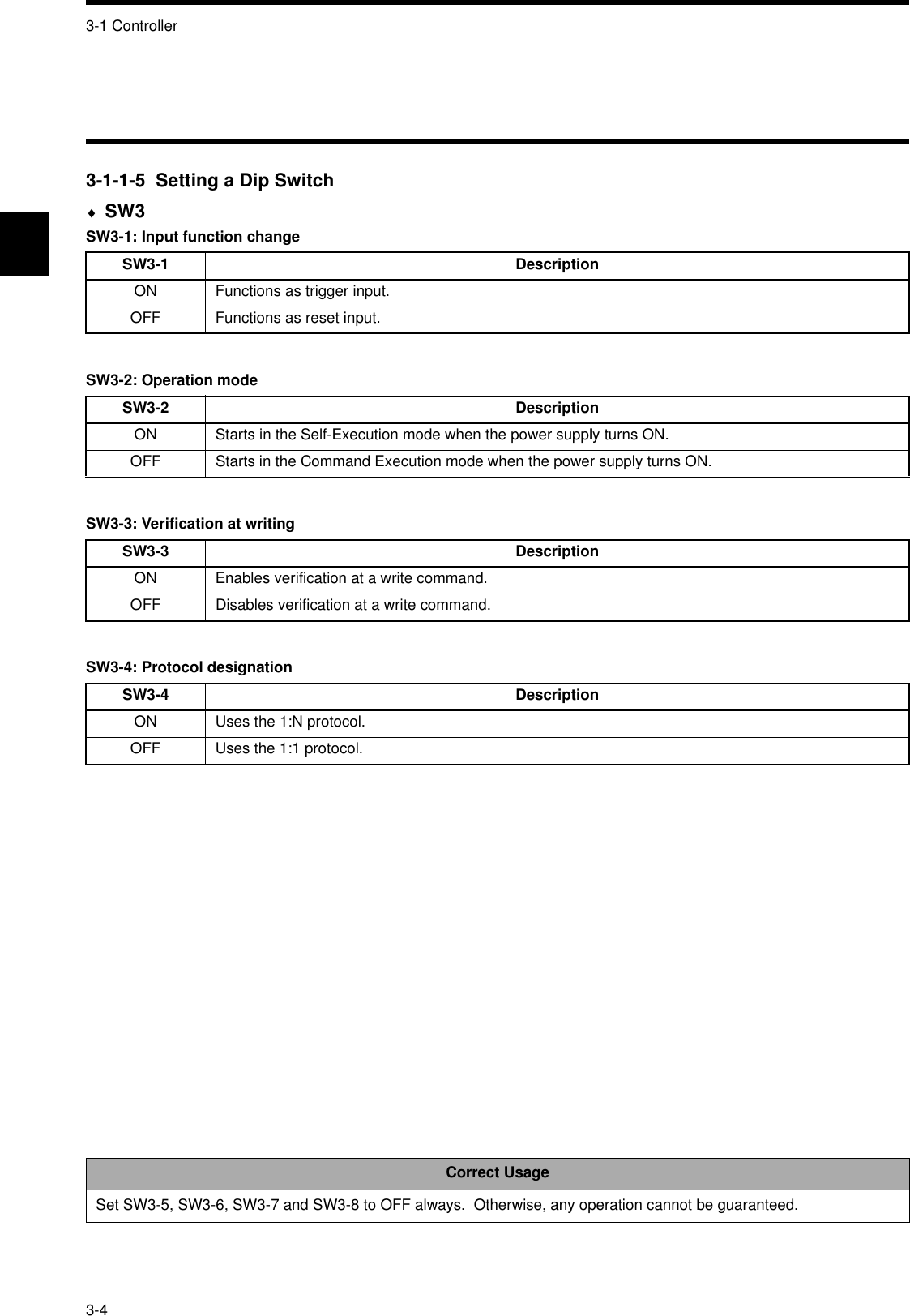
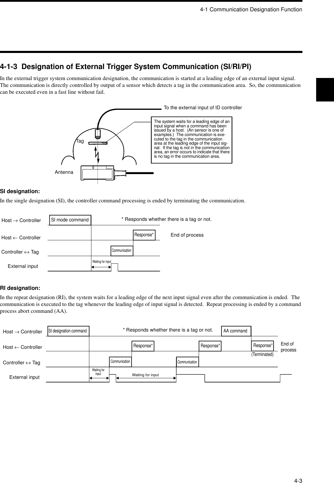
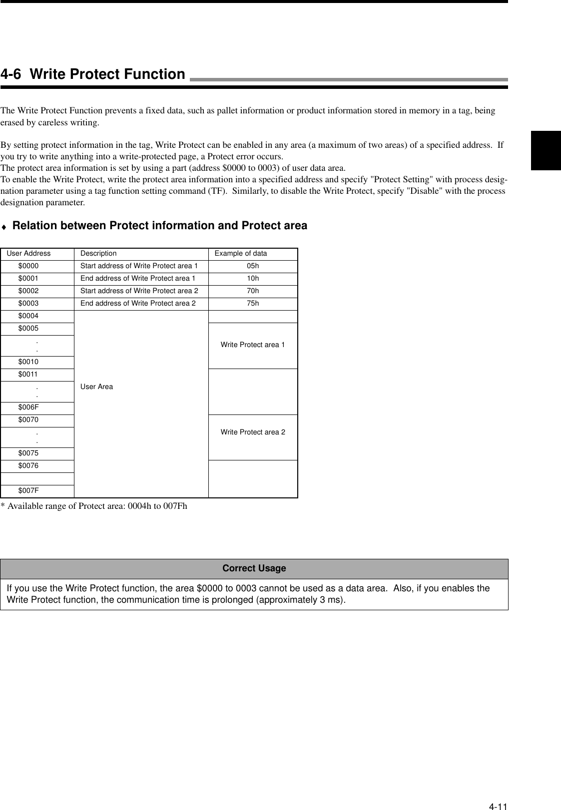
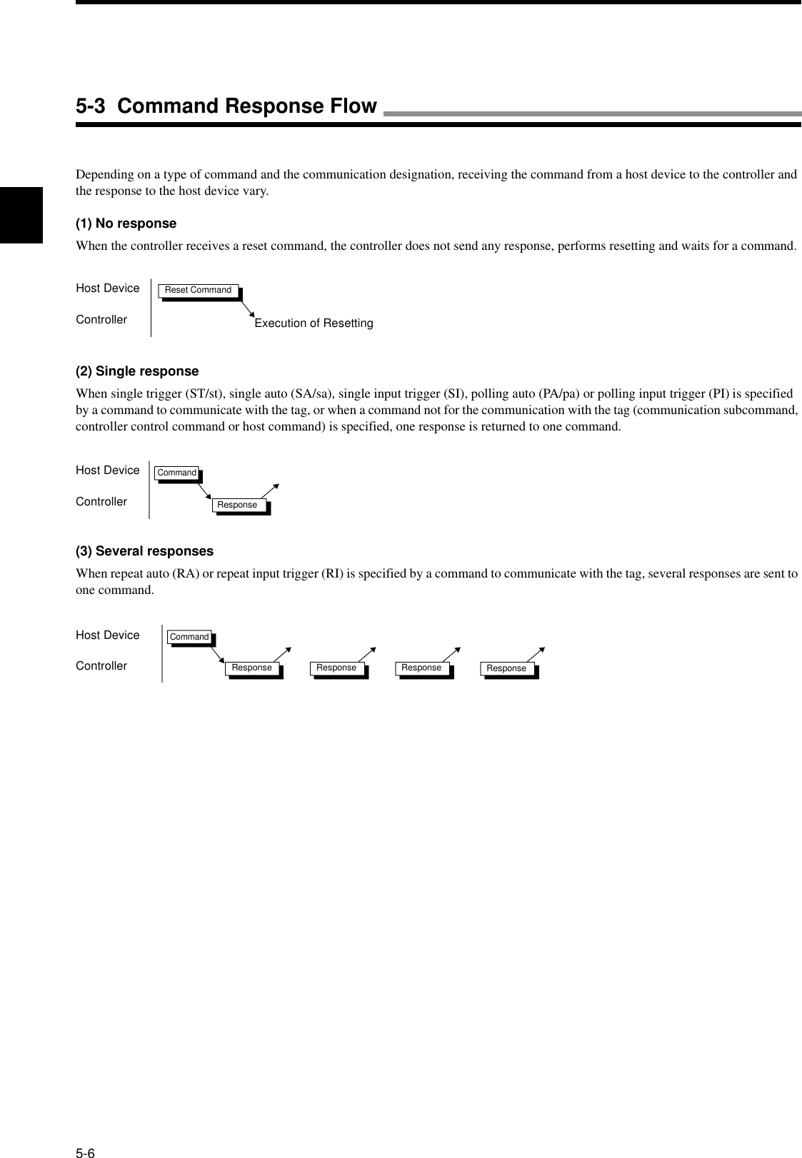
![5-6 Communication Command5-115-6-2 Write (WT)Writes the specified bytes of data from the specified first address into a tag.Example: Writing 4 bytes of data ("11223344") from the address 0010h(Single trigger, hexadecimal code)Sent data: WTSTH 1 0 0 1 0 0 4 1 1 2 2 3 3 4 4 * [CR]Received data: WT 0 0 0 0 * [CR]Communication designation Specifies how to communicate with a tag. For details, refer to the communication desig-nation list.Data designation Specifies a type of transmitted code of data written into a tag."A": ASCII code"H": Hexadecimal codeAntenna designation Fixed to "1".First address of read area Specifies the first address of area, where data is written into, in four hexadecimal digits.Available designation range: 0000h to 007Fh.Number of written bytes Specifies the number of bytes of data written into a tag in two hexadecimal digits.Available designation range: 01h to 80h.Written data Data written into a tag. For a hexadecimal code, two characters per byte.Correct UsageSpecify the number of written bytes so that the sum of the number of written bytes and the first address of written area cannot exceed the tag memory capacity (128 bytes).Example: For the address 0010h, the range between 00h and 70h can be specified.<Command>Command code"WT"Communication designation Datadesig-nationAntenna designa-tionThe first address of written area The number of written bytes Written dataNumber of specified bytes<Response>Command code"WT"Termination code"00"Retrans-mission flagStatus flag](https://usermanual.wiki/Omron/6CYCIDV6700101.Manual/User-Guide-153970-Page-65.png)
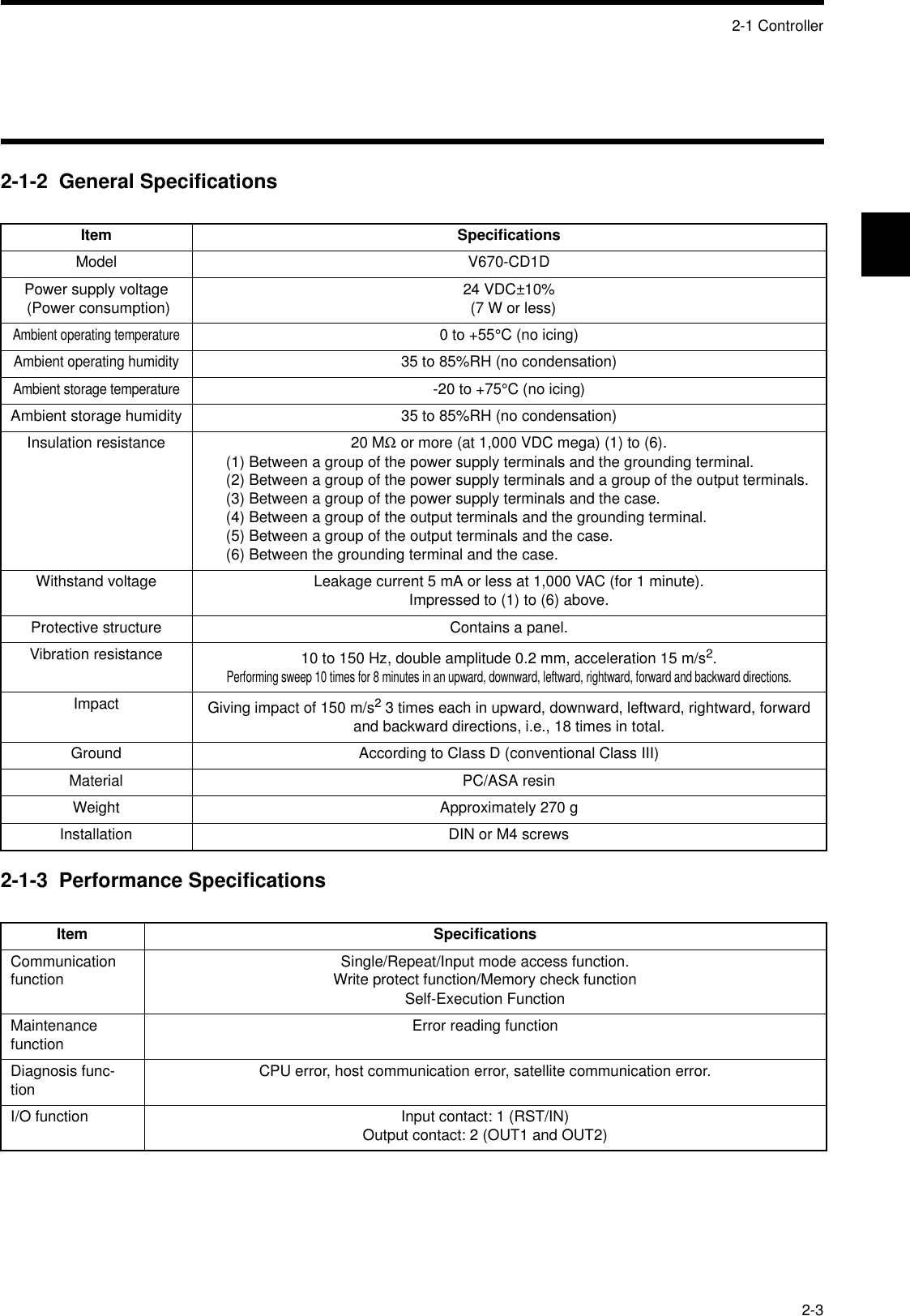
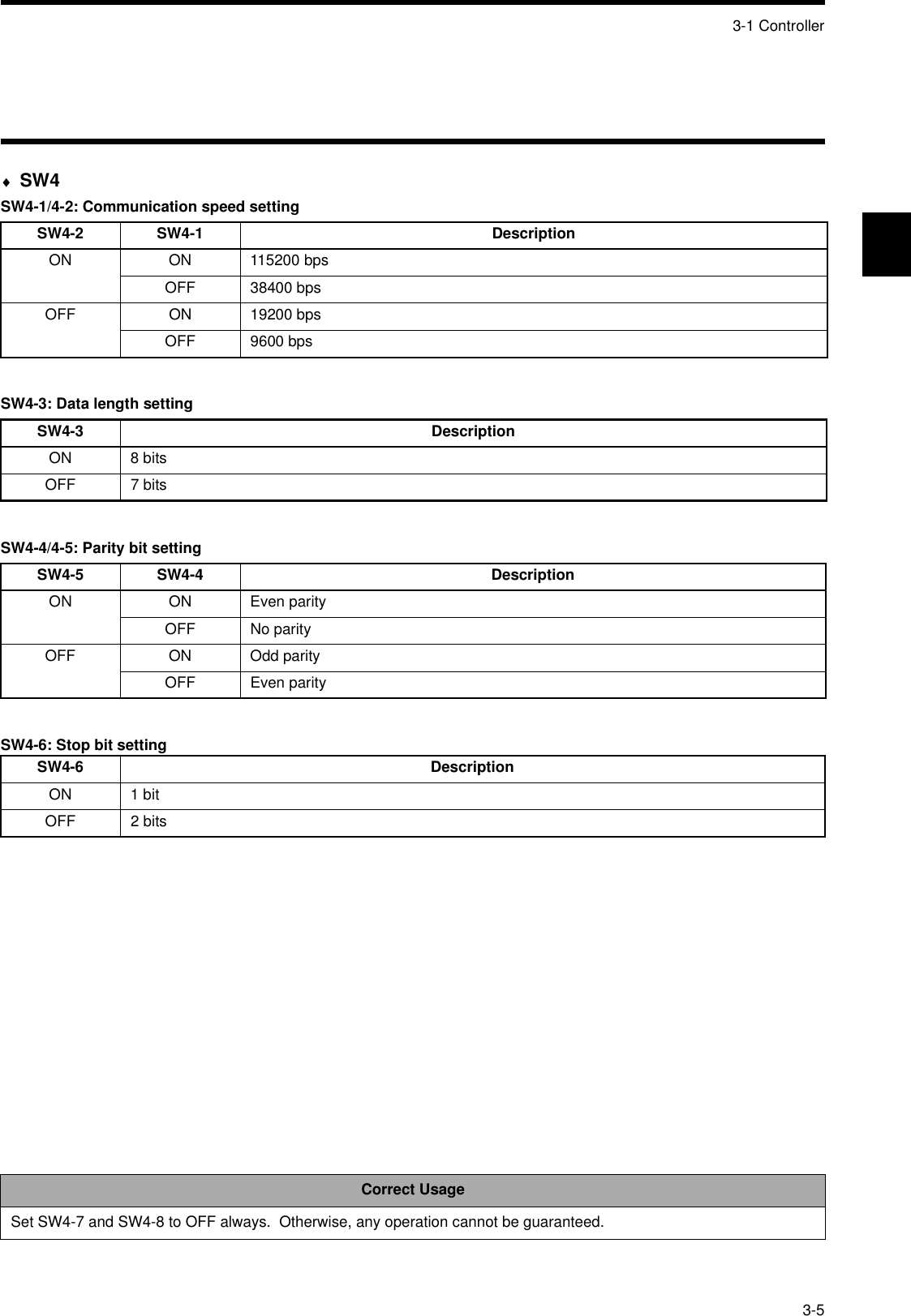
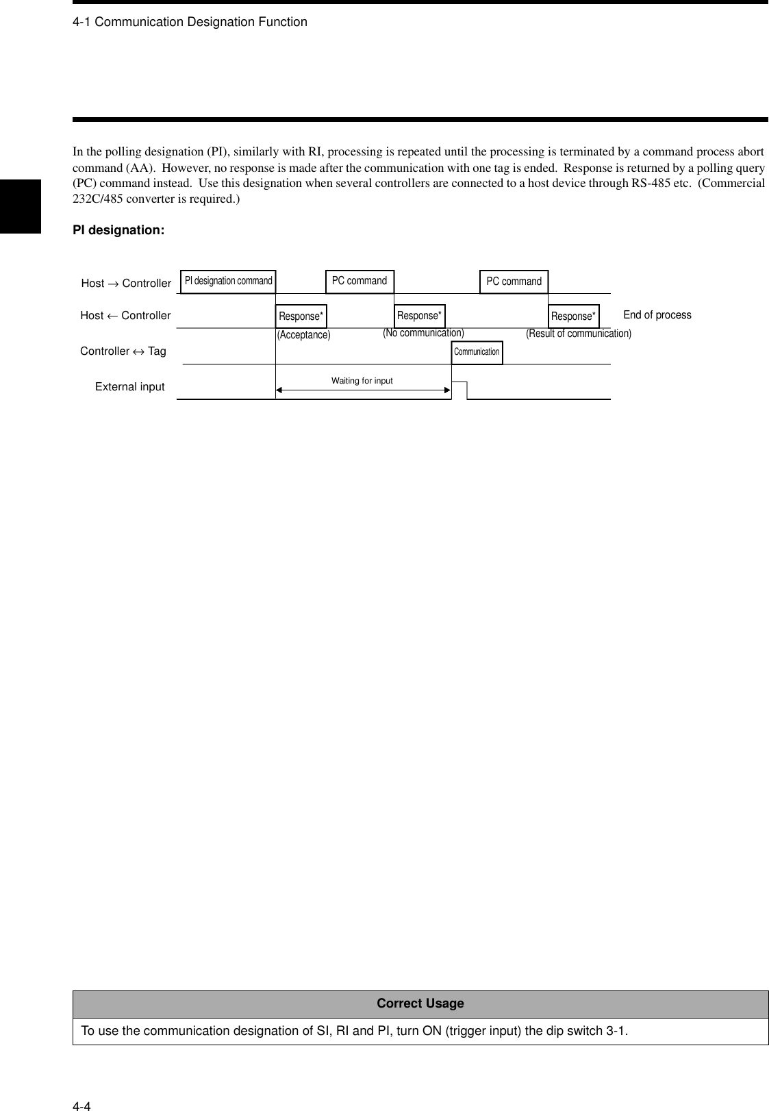
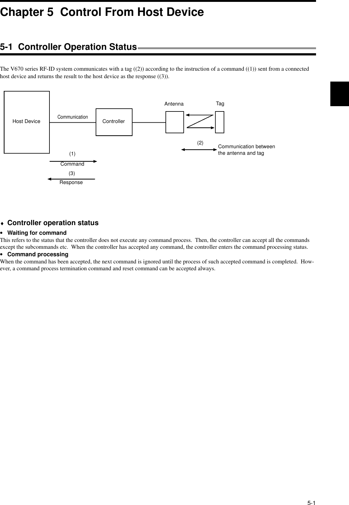
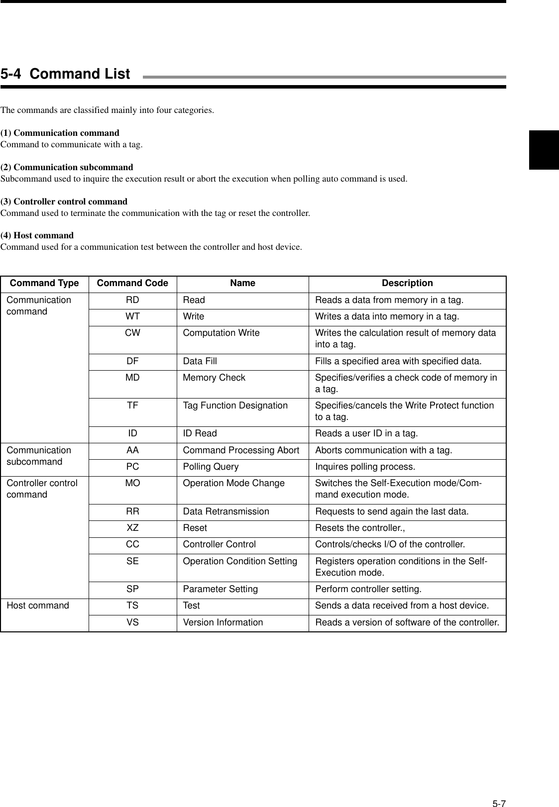
![5-6 Communication Command5-125-6-3 Computation Write (CW)Performs the computation of data in tag memory and computation data in a hexadecimal number and writes the result into the tag. If overflow and underflow occurs in addition and subtraction, respectively, no data is written and "1" is returned to the status flag.Example: Subtracting from 2 bytes of data ("0010") in the computation data ("0002") from the address 0001h and writing the result(Single trigger, initial value "0010")Sent data: CWSTS 1 0 0 0 1 0 2 0 0 2 * [CR]Received data: CW 0 0 0 0 0 0 0 E * [CR]Communication designation Specifies how to communicate with a tag. For details, refer to the communication desig-nation list.Process designation Specifies how to compute."A": Hexadecimal addition"S": Hexadecimal subtractionAntenna designation Fixed to "1".First address of read area Specifies the first address of area, where data is computed, in four hexadecimal digits.Available designation range: 0000h to 007Fh.Number of written bytes Specifies the number of bytes of area, where data is computed, in two hexadecimal dig-its.Available designation range: 01h to 04h.Computation data Specifies a numerical value to be computed in a hexadecimal number.Result data Returns a calculation result data written into the tag. If overflow and underflow occurs in addition and subtraction, respectively, the result data is a data before the calculation. In this case, the sta-tus flag is "1".Correct UsageThis command performs the hexadecimal computation. So, you must specify all the data in a hexadecimal code. More-over, specify an addition area within one page. Otherwise, a command error occurs.<Command>Command code"CW"Communication designationProcess designa-tionAntenna designa-tionThe first address of computation area The number of computation area bytesComputation dataNumber of specified bytes<Response>Command code"CW"Termination code"00"Retrans-mission flagStatus flag Result dataNumber of specified bytes](https://usermanual.wiki/Omron/6CYCIDV6700101.Manual/User-Guide-153970-Page-66.png)
![5-6 Communication Command5-135-6-4 Data Fill (DF)Writes 1 or 2 bytes of the same data into an area specified by the first address and the last address of tag memory. Written data is speci-fied by a hexadecimal code.Example: Writing a fixed data ("00FF") from the address 0000h to 007Fh(Single trigger, writing 2 bytes)Sent data: DFSTW 1 0 0 0 0 0 0 7 F 0 0 F F * [CR]Received data: DF 0 0 0 0 * [CR]Communication designation Specifies how to communicate with a tag. For details, refer to the communication desig-nation list.Data designation Specifies a unit of written data."B": Byte"W": Word (2 bytes)Antenna designation Fixed to "1".First address of written area Specifies the address to write a data into a tag in four hexadecimal digits.Available designation range: 0000h to 007Fh.Last address of written area Specifies the last address to write a data into a tag in four hexadecimal digits.Available designation range: 0000h to 007Fh.Written data Data written into a tag. Specify 1 or 2 bytes of hexadecimal code.Correct UsageWhen you write a fixed data into a specified area, this command can reduce the traffic to a host device and, therefore, the system can be operated fast by this command.<Command>Command code"DF"Communication designation Datadesig-nationAntenna designa-tionThe first address of written area Written data1/2 byteThe last address of written area<Response>Command code"DF"Termination code"00"Retrans-mission flagStatus flag](https://usermanual.wiki/Omron/6CYCIDV6700101.Manual/User-Guide-153970-Page-67.png)
![5-6 Communication Command5-145-6-5 Memory Check (MD)Executes the generating polynomial X16 + X12 + X5 + 1 in an area per check block specified by a user and verifies with a check code added in the check block.Example: Example of address: Adding a check code to 4 bytes of data from the address 0010h(Single trigger)Sent data: MDSTK 1 0 0 1 0 0 6 * [CR]Received data: DF 0 0 0 0 * [CR]* 2 Bytes of data are added to 4 bytes of data. So, the number of specified bytes is 6.Communication designation Specifies how to communicate with a tag. For details, refer to the communication desig-nation list.Process designation Specifies a type of check process."K": Check code calculation"C": Check code verificationAntenna designation Fixed to "1".First address of check block Specifies the first address of check block in four hexadecimal digits.Available designation range: 0000h to 007Dh.Number of bytes of check block Specifies the number of bytes of check block in two hexadecimal digits.Available designation range: 03h to 80h.Status flag Shows the verification result of check code."0": The verification result is normal."1": The verification result is abnormal.Correct UsageDo not write necessary information into the last 2 bytes of an area because 2 bytes are used for a record of check code. For details, refer to "4-5 Memory Check Function".<Command>Command code"MD"Communication designationProcess designa-tionAntenna designa-tionThe first address of check block The number of bytes of check block<Response>Command code"MD"Termination code"00"Retrans-mission flagStatus flag](https://usermanual.wiki/Omron/6CYCIDV6700101.Manual/User-Guide-153970-Page-68.png)
![5-6 Communication Command5-155-6-6 Tag Function Designation (TF)Sets/cancels Write Protect etc. to a tag.Example: Setting Write Protect function of the addresses 0010h to 001Fh to a tag(Single trigger)Setting protect area informationSent data: WTSTH 1 0 0 0 0 0 4 0 0 1 0 0 0 1 F * [CR]Received data: WT 0000*[CR]Setting protect functionSent data: TFSTP 1 * [CR]Received data: TF 0 0 0 0 * [CR]Communication designation Specifies how to communicate with a tag. For details, refer to the communication desig-nation list.Process designation Sets/cancels a function."P": Sets Protect"R": CancelsAntenna designation Fixed to "1".Correct UsageFor details of Write Protect, refer to "4-6 Write Protect Function".<Command>Command code"TF"Communication designationProcess designa-tionAntenna designa-tion](https://usermanual.wiki/Omron/6CYCIDV6700101.Manual/User-Guide-153970-Page-69.png)
![5-6 Communication Command5-165-6-7 ID Read (ID)Reads a user ID of tag.Example: Reading user ID of tag(Single trigger, user ID "1 2 3 4 5 6 7 8")Sent data: IDSTH1*[CR]Received data: ID 0 0 0 0 1 2 3 4 5 6 7 8 * [CR]Communication designation Specifies how to communicate with a tag. For details, refer to the communication desig-nation list. The communication designation "st" only is unavailable.Data designation Fixed to "H" (hexadecimal code).Antenna designation Fixed to "1".Read data User ID data read out of a tag."00000000" to "3FFFFFFF"High order 2 bits are fixed to "0" because of system bit.Correct UsageEvery tag stores its own code. If it needs to be checked only whether there is a tag or not, communication can be done very fast by this command.<Command>Command code"ID"Communication designationDatadesig-nationAntenna designa-tion<Response>Command code"ID"Termination codeRetrans-mission flagStatus flag Read data](https://usermanual.wiki/Omron/6CYCIDV6700101.Manual/User-Guide-153970-Page-70.png)

![5-25Example of BASIC programAn example of program to operate Type V670-CD1D in NEC PC-9801 Series.1:1 Protocol100 ’***** V670-CD1D SAMPLE PROGRAM *****110 CLS120 OPEN “COM:E73NN” AS #1 ’Opens a RS-232C port.130 ’140 ’***** MAIN LOOP ****150 *LOOP160 LINE INPUT “Input TX Data : “, ITD$ ’Inputs a command data.170 TXD$=ITD$+”*”+CHR$(13) ’Sets a data string to be sent.180 PRINT “[TX] : “;ITD$ ’Displays a command data.190 PRINT #1,TXD$; ’Sends a data string.200 GOSUB *RECEIVE ’Receives a data string.210 PRINT “[RX] : “;REC$ ’Displays a response data.220 GOTO *LOOP230 ’240 ’***** RECEIVE DATA *****250 *RECEIVE260 RXD$=” “270 WHILE (LOC(#1)=0):WEND ’Checks a receiving buffer.280 WHILE (INSTR(RXD$,”*”+CHR$(13))=0) ’Checks a termination code.290 RXD$=RXD$+INPUT$(1,#1) ’Reads a received data.300 WEND310 REC$=LEFT$(RXD$,LEN(RXD$)-2) ’Extracts a response data.320 RETRUN330 ’340 END5-11 Example of Communication Program](https://usermanual.wiki/Omron/6CYCIDV6700101.Manual/User-Guide-153970-Page-79.png)
![5-11 Example of Communication Program5-261:n Protocol100 ’***** V670-CD1D SAMPLE PROGRAM *****110 CLS120 OPEN “COM:E73NN” AS #1 ’Opens a RS-232C port.130 ’140 ’***** MAIN LOOP ****150 *LOOP160 LINE INPUT “Input TX Data : “, ITD$ ’Inputs a command data.170 IP$=”00”+ITD$:COSUB *FCS ’Calculates FCS.180 TXD$=CHR$(1)+IP$+OP$+”*”+CHR$(13) ’Sets a data string to be sent.190 PRINT #[TX] : ”;ITD$ ’Displays a command data.200 PRINT #1,TXD$; ’Sends a data string.210 GOSUB *RECEIVE ’Receives a data string.220 PRINT “[RX] : “;REC$ ’Displays a response data.230 GOTO *LOOP240 ’250 ’***** RECEIVE DATA *****260 *RECEIVE270 RXD$=” “280 WHILE (LOC(#1)=0):WEND290 WHILE (INSTR(RXD$,”*”+CHR$(13))=0)300 RXD$=RXD$+INPUT$(1,#1)310 WEND320 IP$=MID$(RXD$,2,LEN(RXD$)-5):GOSUB *FCS ’Calculates FCS330 REC$=MID$(RXD$,4,LEN(RXD$)-7)340 FCS$=MID$(RXD$,LEN(RXD$)-3,2):GOSUB *CHK.FCS ’Checks FCS350 RETRUN360 ’370 ‘***** CALCULATE FCS *****380 *FCS390 K=0400 FOR I=1 TO LEN(IP$)410 TMP$=MID$(IP$,I,1)420 K=K XOR ASC(TMP$)430 NEXT=1440 OP$=HEX$(K)450 RETURN460 ‘470 ‘***** CHECK FCS *****480 *CHK.FCS490 IF FCS$<>OP$ THEN REC$=”FCS ERR!!500 RETURN510 +520 END](https://usermanual.wiki/Omron/6CYCIDV6700101.Manual/User-Guide-153970-Page-80.png)
![7-5 Functions7-107-5-3 Displaying Details of SettingThis function of displaying details of setting of the programming console displays every item of controller setting. By pressing the and then 0 or 1 key, an item to be displayed can be selected.♦Dip switch setting information [0]The dip switch setting information shows every item of controller setting specified by the dip switch.The items are shown as follows:Item DisplayNode No. 00 to 31RS-232C communi-cation setting Communication speed 9600, 19200, 38400, 115200Data length 7, 8Stop bit 1, 2Parity E, O, NInput function changeover RESET, TRIGGEROperation mode at startup OFF, ONProtocol designation 1:N, 1:1Verification at writing OFF, ONShows the dip switch setting information display screen.Shows the parameter information display screen.Shows a node number.Shows the RS-232C setting.Shows the input function setting.Shows the execution mode.Shows a host device.Shows whether Write verification is enabled or disabled.](https://usermanual.wiki/Omron/6CYCIDV6700101.Manual/User-Guide-153970-Page-93.png)
![7-5 Functions7-11♦Parameter information [1]The parameter information shows every item of controller setting stored in internal nonvolatile memory.The items are shown as follows:♦Parameter setting changeIn the parameter setting change, you can change the controller setting stored in internal nonvolatile memory. The figure below shows the character interval monitoring time as an example. When you change any other parameter, the sequence is the same.Item Display ValueCHAR TIME Character interval monitoring time Other than 9600 bps: 0001 to 99999600 bps : 0002 to 9999 x 1 m-secondRES DELY Response Ready time 00 to 99 x 1 m-secondTAG LIMIT Communication restriction time 00 to 99 x 10 m-secondParameter information display Parameter information display* The MONITOR mode only.EEPROM error](https://usermanual.wiki/Omron/6CYCIDV6700101.Manual/User-Guide-153970-Page-94.png)


![Appendix-1Note 1: The code 01011100 (column 5, row 12) is "\" in the ASCII character.b8~b5 0000 10010010 0011 0100 0101 0110 0111 1000 1001 1010 1011 1100 1101 1110 1111b4~b1 0 1 2 3 4 5 6 7 8 9 1011121314150000 0 NUL TC7(DLE)(SP)0@P`pUndefined―タミ0001 1TC1(SOH)DC1!1AQaq 。ア チ ム0010 2 TC2(STX) DC2“2BRbr 「イツメ0011 3 TC3(ETX) DC3#3CScs 」ウ テ モ0100 4 TC4(EOT) DC4$4DTdt 、エ ト ヤ0101 5TC5(NEQ)TC8(NAK) % 5 E U e u .オナユ0110 6 TC6(ACK)TC9(SYN)&6FVf v ヲカニヨ0111 7 BELTC10(ETB)’7GWgw ァキヌラ1000 8 FE0(BS) CAN ( 8 H X h x ィクネリ1001 9 FE1(HT) EM ) 9 I Y i y ゥケノル1010 10 FE2(LF) SUB * : J Z j z ェコハレ1011 11 FE3(VT) ESC + ; K [ k { ォサヒロ1100 12 FE4(FF) IS4(FS) , < L \l| ャシフワ1101 13 FE5(CR) IS3(GS) - = M ] m } ュスヘン1110 14 S0 IS2(RS) . > N ^ n ~ ョセホ゛1111 15 S1 IS1(US) / ? O _ oDELッソマ゜UndefinedAppendixAppendix 1 JIS8 Unit Code List (ASCII Code List)UndefinedUndefinedUndefinedUndefinedHigh order digitLow order digitColumnRow](https://usermanual.wiki/Omron/6CYCIDV6700101.Manual/User-Guide-153970-Page-117.png)