Omron 6CYCIDV6900101 Read / Write Antenna User Manual for Reader Writer Antenna
Omron Corporation Read / Write Antenna Users Manual for Reader Writer Antenna
Omron >
Users Manual for Reader Writer Antenna

Microwave Type RFID System
V690 Series
User’s Manual
Read/Write Antenna, ID Tag, and Link Unit
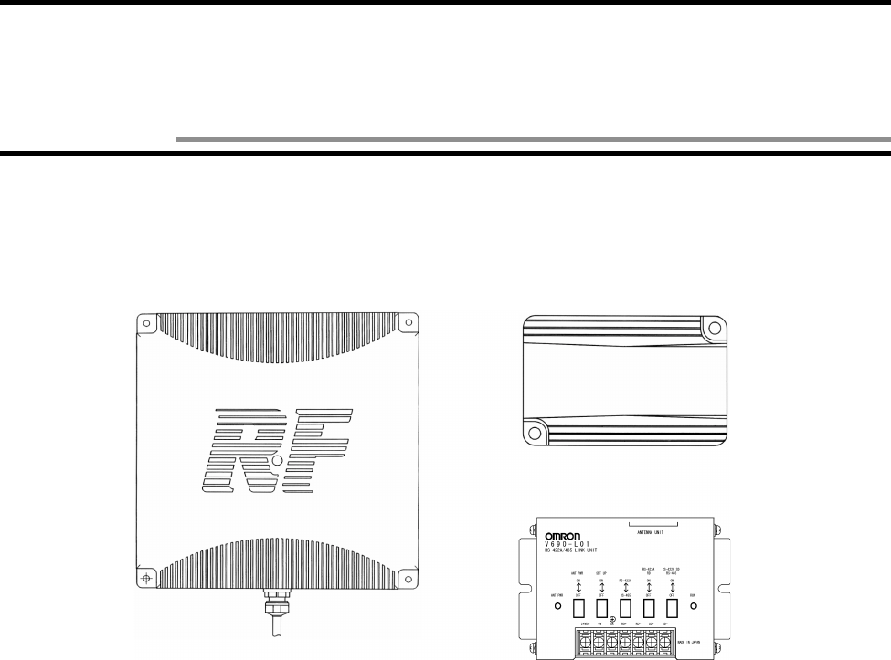
Read/Write Antenna
Model V690-HMG01
ID Tag
Model V690-D8KR01
Link Unit
Model V690-L01
Catalog No. Z149-E1-01

Introduction
Thank you very much for choosing the microwave type RFID system V690 Series. The V690 Series has been developed by OMRON,
based on the advanced technology and extensive experience. This user’s manual describes the functions, performance and usage of
V690 Series.
When you use the V690 Series, follow the instructions below:
• V690 series must be operated by a qualified electrical engineer who experts on knowledge about electricity.
• Read this user’s manual with care, understand the V690 Series fully and use it appropriately.
• Keep this user’s manual handy.
When you use the V690 Series in the following environments, we would like you to operate it within the rating and functions, take
safety measures such as fail-safe system and consult our person in charge.
(1) Use in an unsuitable condition or environment which is not described in the user’s manual
(2) Use for nuclear energy control, railroad, aeronautical system, car, combustion equipment, medical equipment, amusement
facility, safety device, etc.
(3) Use for application which may have a great influence on people’s lives and property and must be executed safely in particu-
lar.
Notes on use
•
••
• Warning symbols and meanings
For safety operation of V690 Series RFID system, the warning symbols below are used in this User’s Manual.
The notes mentioned below gives you an important message for safety operation. Be sure to follow the instruction.
The warning symbols and meaning are as follows:
•
••
• Description of symbol
Notes on safety
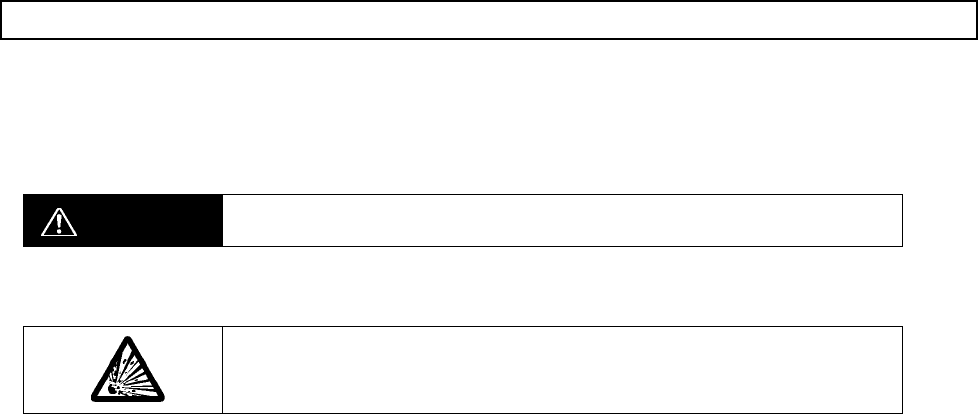
WARNING The hazard or unsafe practice could result in severe injury or death.
•
••
• Explosive!
It may burst under a particular condition.

WARNING
Lithium battery is contained in an ID tag. Do not disassemble, heat above 212 °F (100°C) or incin-
erate the ID tag. Otherwise fire, explosion and/or burns may result..

.
For the safety, be sure to follow the instructions below:
1. Do not operate this device in any flammable, explosive or corrosive gas environment.
2. Do not disassemble, repair nor remodel this device.
3. Tighten the base lock screws and terminal block screws completely.
4. Be sure to use wiring crimp terminal of a specified size.
5. The 24 VDC power supply must meet the following items:
(1) Such 24 VDC power supply must be used for the V690 Series only and must not be connected to any other devices nor appara-
tuses.
(2) Voltage of such DC power supply must be within the specified rating (24 VDC +10%-15%).
6. Be sure to follow any other Warnings, Cautions and Correct Usage mentioned in this manual.
.
1. Do not install model V690-HMG01, model V690-D8KR01 and model V690-L01 in the following areas:
• Place exposed to the direct sunlight.
• Humid place where moisture condensation may occur.
• Place affected by vibration or impact.
2. Preliminary check of installation site.
This device uses the frequency band 2450 MHz for the communication between an antenna and tag. Some of radio equipment, such
as wireless LAN, cellular phone, personal handyphone system and transceiver, motor and switching power supply may generate a
radio wave (noise) which affects the communication with a tag. If you must use this device near such heater, we would like to ask
you to check the influence in advance.
To minimize general influence of noise, follow the instructions below:
• Ground any metallic material located around this device according to Class D (Class III).
• Wire this device keeping away from high voltage and heavy current.
3. Ambient environment and communication range
• The communication range varies depending on the installation site environment. This is because a metal material and the ground
reflect a radio wave, and water and human body absorb it. Locate an antenna and tag in the communication range and check the
radio wave environment in advance.
• The Read/Write antenna model V690-HMG01 has a communication test command to check the radio wave environment at a
working site. (Refer to Section 3-5.)
4. Be sure to ground any ground terminal according to Class D (conventional Class III). Otherwise, performance may deteriorate.
5. Cleaning of model V690-HMG01, model V690-D8KR01 and model V690-L01
• Do not use any thinner. Resin material and case paint are dissolved by thinner.
Remarks
Correct Usage

Contents-1
Chapter 1 Features and System Configuration
1-1 Features ..............................................................................................................................1-1
1-2 System Configuration ........................................................................................................1-2
1-3 Operation Overview ...........................................................................................................1-4
Chapter 2 Specifications and Performance
2-1 Read/Write Antenna Model V690-HMG01 ....................................................................2-1
2-1-1 Specifications ...........................................................................................................2-1
2-1-2 Outside Dimension ...................................................................................................2-1
2-1-3 Signal of Supplied Connector ...................................................................................2-2
2-1-4 Indicator ....................................................................................................................2-2
2-2 ID Tag Model V690-D8KR01 .........................................................................................2-3
2-2-1 Specifications ...........................................................................................................2-3
2-2-2 Outside Dimension ...................................................................................................2-3
2-2-3 Memory Map ............................................................................................................2-4
2-2-4 Battery Life Characteristic .......................................................................................2-5
2-2-5 Battery Voltage Alarm Function ..............................................................................2-5
2-3 RS-422A/485 Link Unit Model V690-L01 ....................................................................2-6
2-3-1 Specifications ...........................................................................................................2-6
2-3-2 Outside Dimension ...................................................................................................2-6
2-3-3 Function ....................................................................................................................2-7
2-4 Connecting Cable ...............................................................................................................2-8
2-4-1 Specifications ...........................................................................................................2-8
2-4-2 Outside Dimension ...................................................................................................2-8
2-5 Communication Performance ..........................................................................................2-10
2-6 Communication Specifications ........................................................................................2-11
Chapter 3 Functions
3-1 Single/FIFO/Multi Mode Access Function ........................................................................3-1
3-2 Communication 2 m Mode/5 m Mode Switching .............................................................3-2
3-3 Radio Wave Channel Switching ........................................................................................3-3
3-4 Simplified Communication Test ........................................................................................3-4
3-5 Communication Test ..........................................................................................................3-5
3-6 Write Protect Function .......................................................................................................3-6
3-7 ID Tag Power-Saving Function .........................................................................................3-8
Chapter 4 Installation and Connection
4-1 Read/Write Antenna and ID Tag .......................................................................................4-1
4-1-1 Installation Environment ..........................................................................................4-1
Contents
Contents

Contents
Contents-2
4-1-2 How to Install Antenna ............................................................................................4-4
4-1-3 Rainproofing of Antenna ..........................................................................................4-5
4-1-4 How to Install Tag ....................................................................................................4-6
4-1-5 How to Connect Connecting Cable to Antenna .......................................................4-7
4-2 How to Wire to Host Device .............................................................................................4-8
4-2-1 How to Wire RS-232C Interface ..............................................................................4-8
4-2-2 How to Wire When Connecting RS-422A/485 ......................................................4-11
4-3 Link Unit ..........................................................................................................................4-16
4-3-1 Installation Environment ........................................................................................4-16
4-3-2 How to Install .........................................................................................................4-16
4-3-3 How to Wire ...........................................................................................................4-17
4-3-4 Switch Setting ........................................................................................................4-20
Chapter 5 Control from Host Device
5-1 Operation Status of Read/Write Antenna and ID Tag .......................................................5-1
5-2 Communication Operation Sequence ................................................................................5-2
5-2-1 Communication Mode with Command ....................................................................5-2
5-2-2 Communication Mode with Communication Designation .......................................5-5
5-2-3 Other Communication Mode ....................................................................................5-8
5-3 Communication Response Format .....................................................................................5-9
5-4 Communication and Communication Designation List ..................................................5-11
5-5 Data Code Designation ....................................................................................................5-14
5-6 Communication Response Flow ......................................................................................5-16
5-7 Tag Communication Command .......................................................................................5-17
5-7-1 Read ........................................................................................................................5-17
5-7-2 ID Code Read .........................................................................................................5-19
5-7-3 Tag Designation Read ............................................................................................5-21
5-7-4 Write .......................................................................................................................5-23
5-7-5 Tag Designation Write ...........................................................................................5-25
5-7-6 Data Fill ..................................................................................................................5-27
5-7-7 Tag Designation Data Fill ......................................................................................5-29
5-7-8 Communication Test ..............................................................................................5-30
5-8 Antenna Operation Command .........................................................................................5-31
5-8-1 Auto Repeat Cancel ................................................................................................5-31
5-8-2 Reset .......................................................................................................................5-32
5-8-3 Request to Respond ................................................................................................5-33
5-8-4 Request to Retransmit ............................................................................................5-34
5-9 Antenna Setting Command ..............................................................................................5-35
5-9-1 Radio Wave Transmission ON/OFF ......................................................................5-35
5-9-2 Communication Range Mode and Radio Wave Channel Selection .......................5-36
5-9-3 Radio Wave Output Status Read ............................................................................5-37
5-9-4 Setting of Time to Wait Tag ...................................................................................5-38
5-9-5 Command Data Response Time Setting .................................................................5-39
5-9-6 Read Data Length Setting ......................................................................................5-40
5-9-7 Host Communication Condition Setting ................................................................5-41

Contents
Contents-3
5-9-8 Station Number Setting ..........................................................................................5-42
5-9-9 Setting Read ...........................................................................................................5-43
5-10 Termination Code List .....................................................................................................5-44
Chapter 6 From Startup to Run
6-1 Trial Operation ...................................................................................................................6-1
6-2 Diagnosis Function ............................................................................................................6-2
6-3 Error List ............................................................................................................................6-3
6-4 Errors and Countermeasures ..............................................................................................6-4
6-5 Maintenance and Inspection ..............................................................................................6-5
6-6 Troubleshooting .................................................................................................................6-6
Chapter 7 Communication Performance and Characteristic Data (Reference)
7-1 Communication Area (Reference) .....................................................................................7-1
7-2 Influence of Ambient Temperature (Reference) ................................................................7-2
7-3 Influence of Tag Rotation Angle (Reference) ...................................................................7-3
7-4 Communication Time (Reference) ....................................................................................7-4
7-5 Mutual Interference Between Antennas (Reference) .........................................................7-6
7-6 Space to Wireless LAN Cellular Phone (Reference) .........................................................7-7
7-7 Influence of Tag Installation Angle (Reference) ...............................................................7-8
7-8 Influence of Back Metal (Reference) ...............................................................................7-10
Appendix
Appendix 1 Glossary ...................................................................................................Appendix-1
Appendix 2 JIS8 Unit Code List (ASCII Code List) ..................................................Appendix-4
Appendix 3 Protective Structure .................................................................................Appendix-5
Appendix 4 Order Format List ....................................................................................Appendix-6

1. Radio interference between radio stations
The frequency 2450 MHz band (2434.25 - 2465.75 MHz) used by the microwave RFID system V690 is designated for second-gen-
eration low-power data communication system (wireless LAN), local area radio station (a license required) for mobile object identi-
fication and specified low-power radio station (no license required) as well as industrial, scientific or medical equipment such as
microwave oven. Therefore, the radio interference is expected in such frequency band. Moreover, the cellular phone and personal
handyphone system (900 MHz - 1900 MHz) may generate the radio interference.
2. Possible trouble due to radio interference
• Communication failure in RFID system
The radio wave from an ID tag to antenna is weak and, therefore, the communication between the antenna and ID tag may fail due
to radio interference caused by any other devices. Keep sufficient space between the RFID system and any other devices. For the
space, refer to Section 7-6.
• ID tag battery power loss
An electronic circuit in the ID tag is started by a radio wave of other device and the battery power may be consumed considerably.
V690 has a tag power-saving function (refer to Section 3-7) to control the battery power. Nevertheless, the battery power may be
still consumed depending on a working environment. So, keep sufficient space between the ID tag and any other devices. For the
space, refer to Section 7-6.
Notes on Interference to Second-Generation Low-Power Data Communication System (Wireless LAN), Cellular Phone, etc.
Second-generation low-power data communication system (wireless LAN)
Low-power data communication system
Mobile object identification (Microwave RFID)
Frequency band of
this product V690
Specified
frequency
band
♦ Communication failure in RFID system ♦ ID tag battery power loss
ID Tag
Antenna
Wireless LAN
ID Tag
Wireless LAN
3. Preparation at working site
(1) Check at working site
1) Before using V690, check that second-generation low-power data communication system (wireless LAN), local area radio station
(microwave RFID system) for mobile object identification or specified low-power radio station (microwave RFID system) does
not work near V690.
2) If V690 causes radio interference to the local area radio station for mobile object identification, change the channel immediately
or stop the V690 emitting the radio wave. Then, we would like you to contact us to take necessary actions to avoid interference
(e.g., partitioning).
3) If V690 causes radio interference to the second-generation low-power data communication system or specified low-power radio
station for mobile object identification or if any other trouble happens, feel free to contact us.
(2) Product label and caution label
The product label and caution label come with the product.
• Affix the product label to a visible position on an antenna unit.
• Affix the caution label to a visible position near the antenna. The caution label must show the contact address or phone number of
a person in charge of installation or any other related information.
(3) Meaning of product label
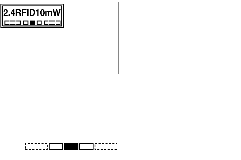
• 2.4: Radio equipment which uses the frequency band 2.4 GHz.
• RFID: The application of Radio Frequency Identification.
• 10 mW: A value of antenna power.
• !!!: Frequency band as follows:
The V690 antenna uses the frequency band 2450 MHz and, therefore "2450" is marked.
♦ Product label
The frequency 2450 MHz band of this device is designated for second-gen-
eration low-power data communication system (wireless LAN), local area
radio station (a license required) for mobile object identification and specified
low-power radio station (no license required) as well as industrial, scientific
or medical equipment such as microwave oven.
1) Before using this device, check that second-generation low-power data
communication system (wireless LAN), local area radio station (micro-
wave RFID system) for mobile object identification or specified low-power
radio station (microwave RFID system) does not work near this device.
2) If this device causes radio interference to the local area radio station for
mobile object identification, change the frequency band immediately or
stop this device emitting the radio wave. Then, we would like you to con-
tact below to take necessary actions to avoid interference (e.g., partition-
ing).
3) If this device causes radio interference to the second-generation low-
power data communication system or specified low-power radio station
for mobile object identification or if any other trouble happens, feel free to
contact below.
Contact:
♦ Caution label
Frequency band: 2440 2450 2455 MHz
Frequency band: 2470.75 - 2483.5 MHz
2400 - 2427
A manual revision history code is added to the end of catalog number shown at the left lower part of front cover
and back cover
Manual Revision History
Revision
Code Date of
Revision Reason of Revision / Revised Page
-- October 2000 First Edition
Catalog No. SCLB-Z149-E1-01!
!!
!
Revision code
1-1
The V690 Series is the microwave type RFID system which has achieved long-range and high-performance communication. This V690
system is the most suitable for an assembly line, physical distribution, and product control applications.
(1) Read/Write Antenna Model V690-HMG01
• Consists of an antenna unit which communicates with the ID tag, and a controller unit which controls the communication.
• The antenna unit has achieved the transmission speed 600 kbps and maximum communication range 5 m.
• The antenna uses circularly polarized wave as radio wave. So, the ID tag facing the antenna can communicate at any rotating
angle on the medial axis. The maximum communication range varies depending on the tag angle.
• This antenna is a specified low-power radio station and, therefore, any radio station license is not required.
• The Multi Access function which enables to access several tags in the antenna communication area and FIFO (First-In First-Out)
function which enables to access the tags coming in the communication area sequentially one by one.
• By a command from a host device, the communication 2 m Mode and 5 m Mode can be switched to each other and a radio wave
channel can be switched at a working site. You can select the most suitable communication range at a working site and prevent
the mutual interference between antennas easily.
• The controller contains both of the RS-232C and RS-422A interfaces. So, it can connect to a general-purpose PC or programma-
ble controller (PLC) which have RS-232C. Also, several antennas can be connected to one host device.
• A simplified communication test function, which can check the communication with a tag without a host device, and a communi-
cation test, which can check a radio wave environment at a working site, are available.
(2) ID Tag Model V690-D8KR01
• This tag contains a battery and the memory capacity is 8 kbytes.
• Write Protect is available to disable writing by 256 bytes.
• Protective structure based on the IEC Standard IP67 (JEM Standard IP67g) has been achieved. So, this tag can be used even in a
place splashed with water and oil.
• The battery life is 5 years at 25°C (a reference value). The battery is not replaceable, but a power-saving function and battery
voltage alarm function are available.
(3) RS-422A/485 Link Unit Model V690-L01
• Use when the communication with a host device is made through the RS-422A or RS-485.
• The power supply to the Read/Write antenna can be turned ON/OFF, the operation/setting mode can be switched, RS-422A/RS-
485 can be switched and terminating resistance can be turned ON/OFF.
Read/Write Antenna
Model V690-HMG01 ID Tag
Model V690-D8KR01
RS-422A/485 Link Unit
Model V690-L01
Chapter 1 Features and System Configuration
1-1 Features
1-2
•
••
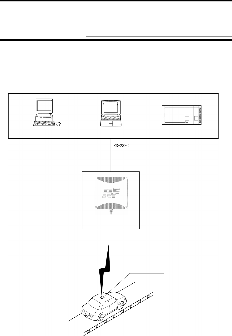
•Example of system configuration of model V690-HMG01 (1:1 connection in a host communication through RS-
232C)
Model V690-HMG01 contains a serial interface based on RS-232C and can connect to a general-purpose PC or programmable con-
troller (PLC) easily. All the communications with the tag are controlled according to the instructions (by commands) from a host
device.
<Host Devices>
Desktop PC Notebook PC Programmable Controller
(PLC)
Cable
Model V690-A4!
Read/Write Antenna
Model V690-HMG01
Communication ID Tag
Model V690-D8KR01
1-2 System Configuration
1-2 System Configuration
1-3
•
••
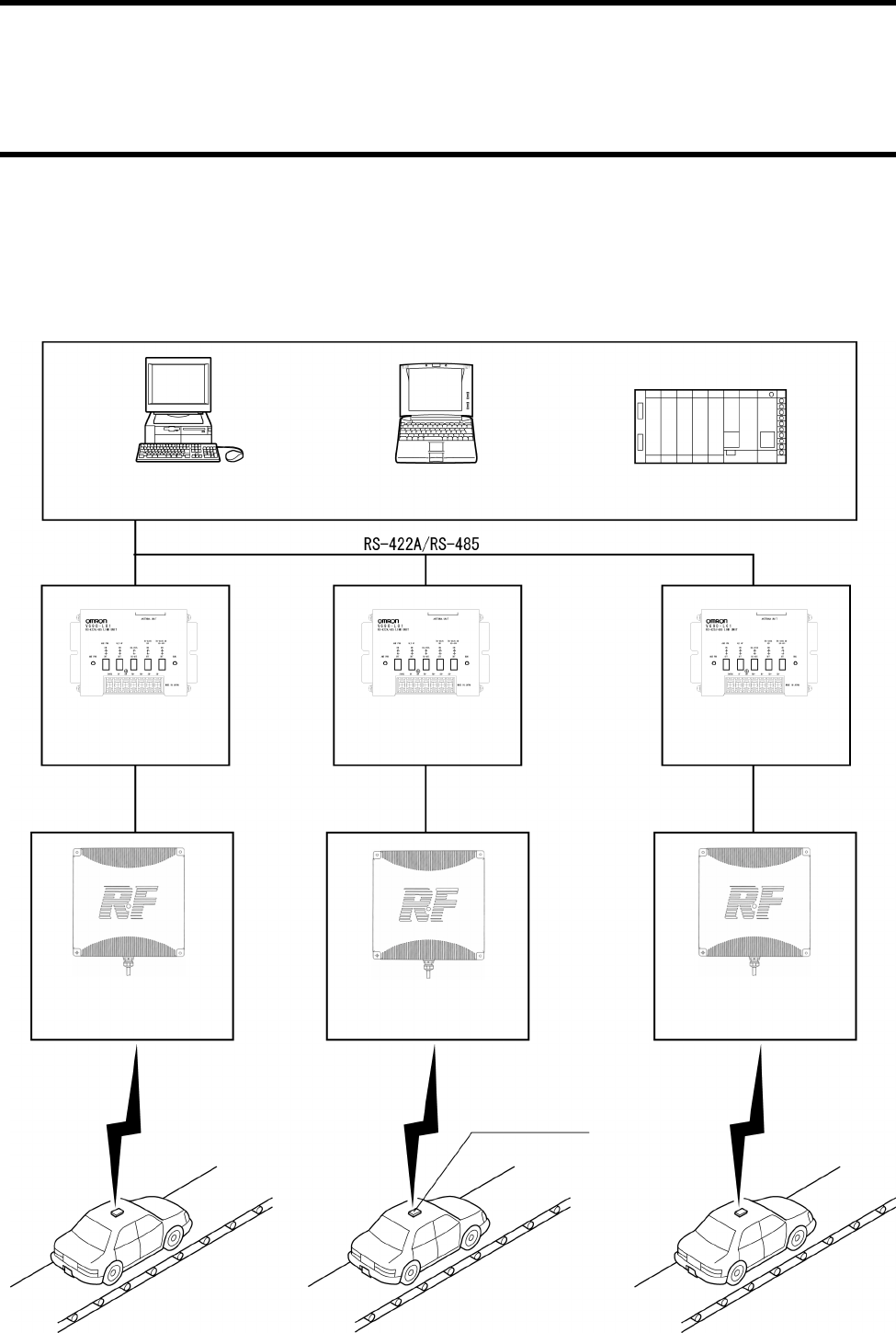
•Example of system configuration of Model V690-HMG01 (1:N connection in a host communication through RS-
422A (4-wire)/RS-485 (2-wire))
Model V690-HMG01 contains the RS-422A/485 interface and can connect a maximum of 32 RS-422A/485 link units model V690-
L01 to one general-purpose PC or programmable controller (PLC). A maximum length of RS-422A/485 is 300 m.
<Host Devices>
Desktop PC Notebook PC Programmable Controller
(PLC)
Cable
Model V690-A5!
Read/Write Antenna
Model V690-HMG01
Communication ID Tag
Model V690-D8KR01
Communication
Communication
Read/Write Antenna
Model V690-HMG01
Read/Write Antenna
Model V690-HMG01
Link Unit
Model V690-L01
Cable
Model V690-A5!
Cable
Model V690-A5!
Link Unit
Model V690-L01
Link Unit
Model V690-L01
1-4
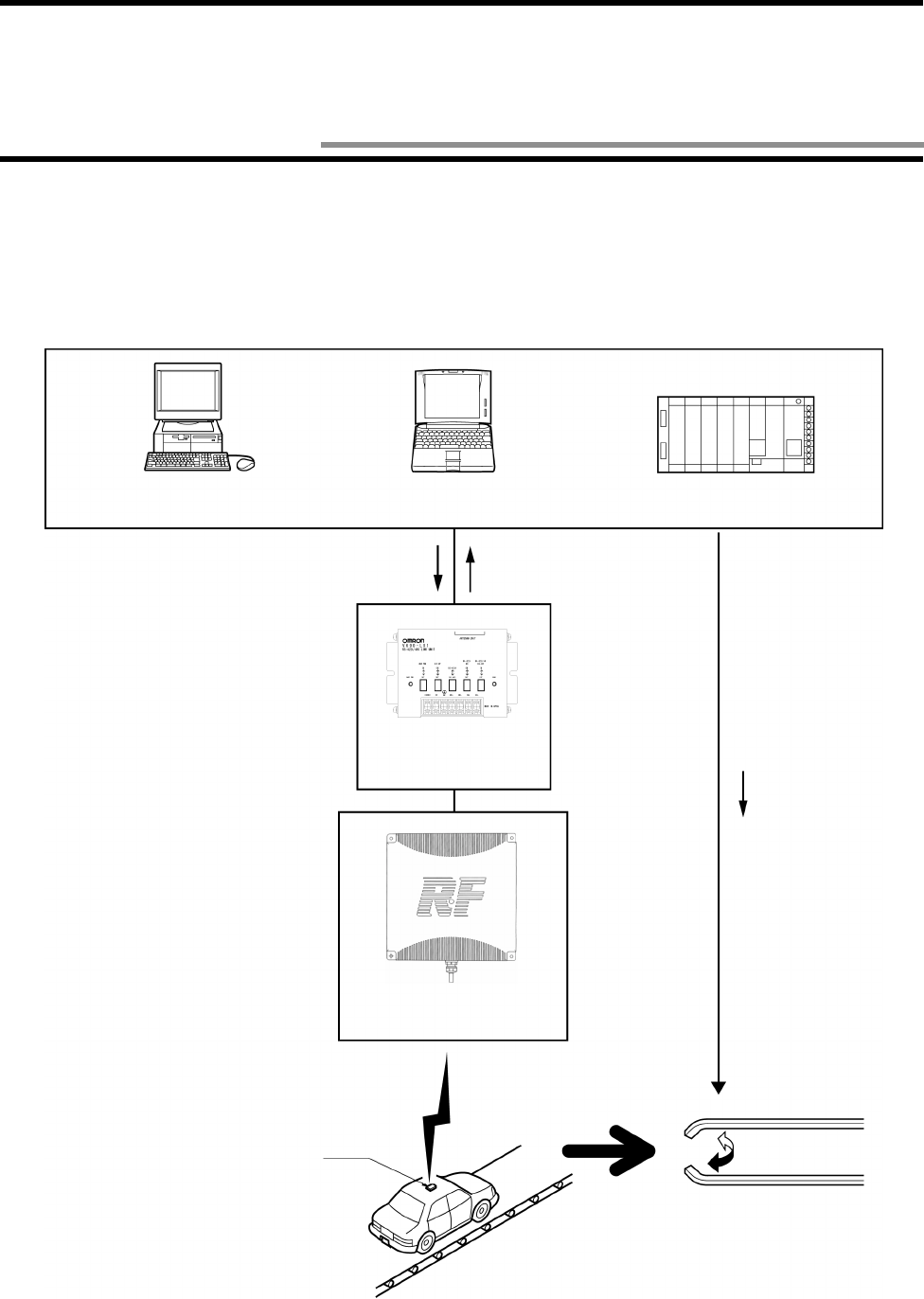
Showing an example of assignment in car transportation, the V690 Series operation overview is described below.
The ID tag is mounted on a car body and the destination is assigned to the car according to the destination information stored in the ID
tag.
<Host Device>
(1)When an auto command is sent from a host device to the Read/Write antenna, the antenna is ready to work and waits for an ID tag.
(2)When any ID tag has come in the antenna’s communication area, the antenna returns data of memory area specified by the auto com-
mand (Read) as a response.
(3)Based on the data, the host device controls a transportation device and assigns the destination.
Desktop PC Notebook PC Programmable Controller
(PLC)
Read/Write Antenna
Model V690-HMG01
Communication
ID Tag
Link Unit
Model V690-L01
Auto command
(Read) Response
I/O Control
Execution
(Assignment)
1-3 Operation Overview
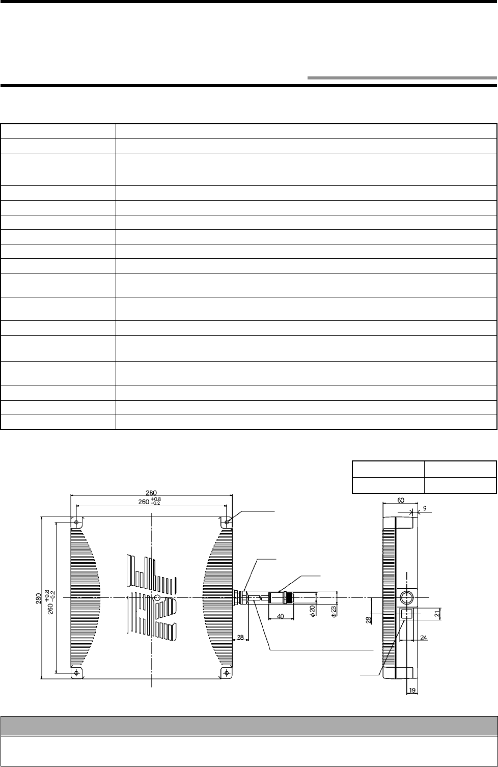
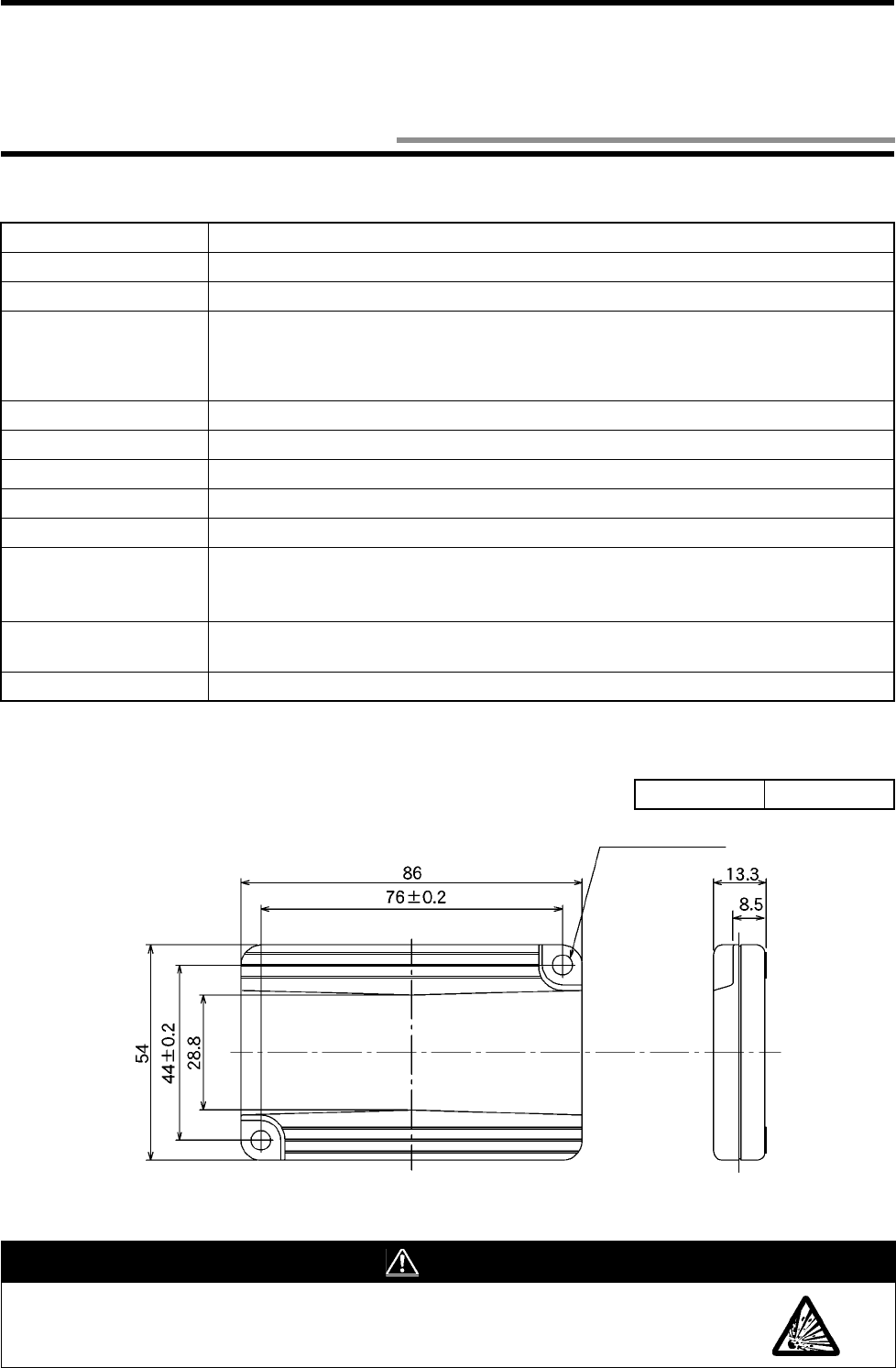
2-1
2-1-1 Specifications
2-1-2 Outside Dimension
Item Specifications
Emitting frequency 2450 MHz band (2434.25 - 2465.75 MHz)
Power supplied to
antenna 5 mW in the communication range 2 m mode. 10 mW in the communication range 5 m
mode (specified low-power radio station - radio equipment for mobile object identification).
* A user is not required to apply a license for radio station.
Power supply 24 VDC +10%/-15%
Consumption current 0.5 A or less.
Ambient operating temperature
-20 to +60°C (without icing)
Ambient operating humidity
35 to 85%RH (without moisture condensation)
Ambient storage temperature
-20 to +60°C (without icing)
Ambient storage humidity 35 to 85%RH (without moisture condensation)
Insulation resistance 20 MΩ or more (at 100 VDC mega).
Between a group of cable terminals and a case.
Withstand voltage 1,000 VAC, 50/60 Hz for 1 minute, detected current 1 mA or less.
Between a group of cable terminals and a case.
Protective structure IP62 (IEC60529 Standard) * A cable outlet turns downward.
Vibration resistance
10 to 150 Hz, single amplitude 0.35 mm, maximum acceleration 50 m/s
2
. Performing sweep 10 times
for 8 minutes in upward, downward, leftward, rightward, forward and backward directions.
Impact resistance Giving impact of 150 m/s2 3 times each in upward, downward, leftward, rightward, forward
and backward directions, i.e., 18 times in total.
Indicator Power supply, radio wave emission, host transmission, tag transmission.
Cable length 0.5 m. A round connector (waterproof) comes with the cable.
Weight 2.6 kg or less (including a cable of 0.5 m in length and connector)
Correct Usage
Protective structure IP62 of the antenna is the protection against the drop of water. If the antenna is splashed with water
spray or water jet flow, cover the antenna with a protection plate. (Refer to "Appendix 3 - Protective Structure".)
4-φ6 Mounting hole
Case material ABS resin
Cable Vinyl chloride
Bush
Connector
Vinyl insulation round cord, φ7.5, 12-core,
0.5 m in length
Indicator
(Unit: mm)
Chapter 2 Specifications and Performance
2-1 Read/Write Antenna Model V690-HMG01
2-1 Read/Write Antenna Model V690-HMG01
2-2
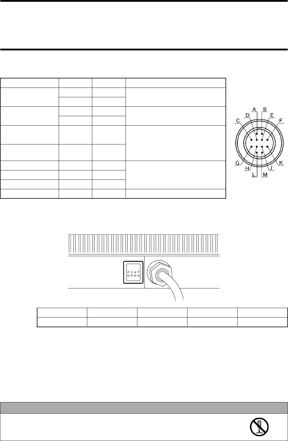
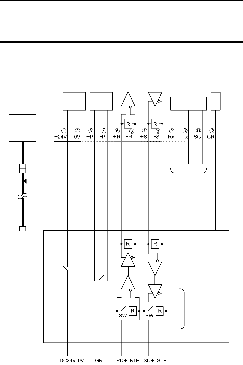
2-1-3 Signal of Supplied Connector
2-1-4 Indicator
(1) The items below can be checked through the antenna indicator.
P (Power): Turns on when 24 VDC power is being supplied to the antenna.
C (Carrier): Turns on when the antenna is emitting a radio wave.
H (Host): Turns on when the antenna is sending data to a host device.
T (Tag): Turns on when the antenna is sending data to a tag.
(2) By enabling the setting mode, you can check the communication range to a tag without connecting to a host device. Refer to Section
3-4.
(3) If an operation fails, troubleshoot according to those indicators which turn on or blink. Refer to Section 6-2.
Item Symbol
Pin Number
Usage
Power supply +24V A Supply 24 VDC.
0V B
Setting +P C
Short-circuit at the setting mode. Refer to Section 5-1.
Do not connect at the operation mode
-P D
RS-422A RD
(Receiving) RD+ E Use for the communication in RS-422A.
(Terminating resistance 220 Ω is con-
nected to both of RD and SD in the
antenna.) Do not connect when RS-
232C is used.
RD- F
RS-422A SD (Send-
ing) SD+
SD- G
H
RS-232C Receiving Rx J Use for the communication in RS-232C.
Do not connect when RS-422A/485 is
used.
RS-232C Sending Tx K
RS-232C Signal 0V SG L
Frame ground GR M Ground according to Class D.
Indicator P (Red) C (Red) H (Red) T (Red)
Meaning Power supply
Radio wave emission
Host transmission Tag transmission
Correct Usage
Do not disassemble it nor touch the inside when the power supply turns on. Otherwise, trouble
may be caused.
Pin Layout
2-3
2-2-1 Specifications
2-2-2 Outside Dimension
Item Specifications
Memory capacity 8 Kbytes
Type of memory SRAM (volatile memory). Data is backed up by a battery.
Memory life (Reference
value) 5 Years.
* Ambient temperature 25°C. For details, refer to Section 2-2-4.
Battery not replaceable.
Battery voltage alarm function.
Ambient operating temperature
-20 to +60°C in the communication. -25 to +70°C not in the communication (without icing).
Ambient operating humidity
35 to 85%RH (without moisture condensation)
Ambient storage temperature
-25 to +70°C (without icing)
Ambient operating humidity
35 to 85%RH (without moisture condensation)
Protective structure IP67 (IEC60529 Standard) / IP67g (JEM1030 Standard)
Vibration resistance 10 to 2,000 Hz, single amplitude 0.75 mm, maximum acceleration 150 m/s2. Performing
sweep 10 times for 15 minutes in upward, downward, leftward, rightward, forward and back-
ward directions.
Impact resistance Giving impact of 500 m/s2 3 times each in upward, downward, leftward, rightward, forward
and backward directions, i.e., 18 times in total.
Weight 60 g or less.
Case material ABS resin
WARNING
Never disassemble, pressure, deform, heat to 100°C or more nor burn an ID tag. The ID tag con-
tains lithium battery and it may ignite, burst or burn.
2-
φ
4.5 Mounting hole
(Unit: mm)
2-2 ID Tag Model V690-D8KR01
2-2 ID Tag Model V690-D8KR01
2-4
2-2-3 Memory Map
♦
♦♦
♦User data
Memory capacity of user data of ID tag is 8,192 bytes. Minimum unit of memory is 1 byte and the memory is specified by the address
(0000h to 1FFFh). h: Hexadecimal number
♦
♦♦
♦System data
In addition to user data, system data is included in the ID tag memory. Use an upper case such as "DATE" to specify the address. For
the details of reading and writing, refer to Sections 5-7-1 to 5-7-5.
Data address Bit Writing by
user Related
commands
76543210
0000h to
1FFFh User data (8 kbytes)
Initial value: all 00h Sections 5-7-1, 5-7-
3 to 5-7-7
Content Bit Writing by
user Related commands
76543210
Date of manu-
facture
Thousand’s place of Year Hundred’s place of Year
X
Sections 5-7-1 and
5-7-3
Ten’s place of Year One’s place of Year
Ten’s place of Month One’s place of Month
Ten’s place of Day One’s place of Day
ID code 8 Bytes. * A value inherent in tag. X Section 5-7-2
Write Protect
data 4 Bytes. * Refer to Section 3-6
Initial value: Write Protect disabled in all the areas. Sections 5-7-1, 5-7-
3 to 5-7-5
Sleep waiting
time 2 Bytes * Refer to Section 3-7.
Initial value: 4800 (8 minutes). Set by 100 msec.

2-2 ID Tag Model V690-D8KR01
2-5
2-2-4 Battery Life Characteristic
The ID tag contains a battery. The charts below show the relation between the ID tag battery life, number of communication bytes and
ambient temperature. The battery life means the time until the battery voltage alarm has been given.
2-2-5 Battery Voltage Alarm Function
When the voltage of ID tag battery becomes low, "7B" is returned to the termination code when a tag communication command (Read
or Write) is executed.
Correct Usage
After the termination code 7B was generated, the ID tag can be used for approximately one month in a normal situation.
However, we recommend you to replace the tag with a new one immediately.
8
7
6
5
4
3
2
0
1
02468
Communication data and battery life (at the ambient temperature 25°C)
Battery life
(Year)
Communication data k
byte (100 times/day)
Conditions
• Write (single trigger without verification)
•One tag
• The tag is in a sleep mode after a command is
executed.
Example of command
[STX]0080W3SUAA0000 0100
[Written data] [ETX]
Ambient temperature and tag battery life (256 bytes x 100 times/day)
Battery life
(Year)
Ambient temperature
2-6
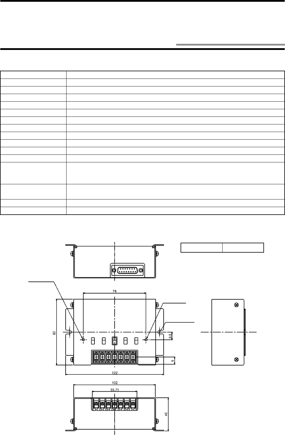
2-3-1 Specifications
2-3-2 Outside Dimension
Item Specifications
Interface specifications RS-422A, RS-485
Power supply voltage 24 VDC
Allowable voltage 20.4 to 26.4 VDC
Power consumption 6 W or less
Operating temperature 0 to +55°C (without icing)
Operating humidity 35 to 85%RH (without moisture condensation)
Storage temperature -10 to +65°C (without icing)
Storage humidity 35 to 85%RH (without moisture condensation)
Insulation resistance
20 M
Ω
or more (at 100 VDC mega). Between a group of cable terminals and a case, excluding GR.
Withstand voltage
1,000 VAC, 50/60 Hz for 1 minute, detected current 20 mA or less. Between a group of cable terminals and a case, excluding GR.
Protective structure IP30 (IEC60529) * Connected to a connector of the dedicated cable model V690-A5!.
Vibration resistance 10 to 150 Hz, single amplitude 0.35 mm, maximum acceleration 50 m/s2. Performing
sweep 10 times for 8 minutes in upward, downward, leftward, rightward, forward and back-
ward directions.
Impact resistance Giving impact of 150 m/s2 3 times each in upward, downward, leftward, rightward, forward
and backward directions, i.e., 18 times in total.
Ground According to Class D.
Weight 450 g or less
Case material SECC (Iron)
Antenna indicator
Operation indicator
2-φ4.5 Mounting hole
(Unit: mm)
2-3 RS-422A/485 Link Unit Model V690-L01
2-3 RS-422A/485 Link Unit Model V690-L01
2-7
2-3-3 Function
This link unit functions as a relay to operate a host device and antenna through RS-422A/RS-485 communication. For an example of
internal circuit, refer to Section 4-2-2.
ANT PWR SET UP RS-422A/RS-485 RS-422A RD
(Receiving) RS-422A SD
(Sending) RS-485
By setting it to ON,
the power is sup-
plied to the antenna.
By setting it to OFF,
the power is not sup-
plied to the antenna.
By setting it to ON,
the setting mode ter-
minals "+P" and "-P"
are short-circuited.
By setting it to OFF,
"+P" and "-P" are dis-
connected from each
other.
RS-422A and RS-
485 are switched to
each other.
For RS-422A, the termi-
nating resistance (220
Ω
) of RS-422A RD
(Receiving) is turned
ON/OFF.
For RS-485, the termi-
nating resistance can-
not be turned ON/OFF.
For RS-422A, the ter-
minating resistance
(220
Ω
)
of RS-422A
SD (Sending) is
turned ON/OFF.
For RS-485, the ter-
minating resistance
is turned ON/OFF.
Correct Usage
Be sure to connect a grounding wire. Otherwise, an error may occur in an operation.
Do not touch any terminal when the power supply turns on. Otherwise, an error may occur in an
operation.
Do not disassemble it nor touch the inside when the power supply turns on. Otherwise, trouble
may be caused.
Connect a connector
(D-SUB 15-pin) of the
RS-422A/RS-485 link
unit connecting cable.
Indicator "RUN"
Turns on when the 24
VDC power supply
turns on.
Indicator "ANT PWR"
Turns on when 24
VDC is supplied to the
antenna.
Connect 24 VDC
power supply.
Ground accord-
ing to Class D.
Connect a communication
line of RS-422A/RS-485.
Switch Function
2-8
2-4-1 Specifications
2-4-2 Outside Dimension
(1) RS-232C connecting cable (for IBM PC compatible PC)
Item Specifications
Cable outer diameter 7.5 mm
Cable color Dark gray
Sheathing material Vinyl chloride resin
Number of cores 12 (3 of AWG22 for power supply and GR and 9 of AWG26 for signals)
Insulation resistance 50 MΩ/km or more. Between a group of cables and cable sheath.
Withstand voltage 500 VAC for 1 minute. Between a group of cables and cable sheath.
Item Specifications
Connector at antenna Round connector (waterproof)
Connector at host device D-SUB 9-pin, female (not waterproof)
Model Cable Length
Model V690-A40 2 m
Model V690-A41 3 m
Model V690-A42 5 m
Model V690-A43 10 m
Model V690-A44 15 m
Connector (at PC)
Connection
label
Inch screw thread (M2.54)
Green/Yellow
Vinyl insulation round cord φ7.5
Connector (at antenna)
Brown
Blue
Light Green
Black
Cable length
(Unit: mm)
2-4 Connecting Cable
2-4 Connecting Cable
2-9
(2) RS-422A/485 link unit connecting cable
Item Specifications
Connector at antenna Round connector (waterproof)
Connector at link unit D-SUB 15-pin, male (not waterproof)
Model Cable Length
Model V690-A50 2 m
Model V690-A51 3 m
Model V690-A52 5 m
Model V690-A53 10 m
Model V690-A54 20 m
Model V690-A55 30 m
Model V690-A56 50 m
Connector (at link unit)
Cable length
Metric screw
thread (M2.5)
Connection
label
Vinyl insulation round
cord φ7.5
Connector (at antenna)
(Unit: mm)
2-10
Item Specifications
Frequency 2450 MHz band (microwave, 2434.25 - 2465.75 MHz)
Type of radio station Specified low-power radio station - radio equipment for mobile object identification (RCR
STD-29 Version 3.0)
* A user is not required to apply a license for radio station.
Transmission output at
modulation 5 mW for 2 m mode and 10 mW for 5 m mode.
Polarized wave Circularly polarized wave
Communication range 2 m mode/5 m mode switched by a host command. (Section 3-2)
2 m mode: 0.2 to 2.0 m (Reference value)
5 m mode: 0.2 to 5.0 m (Reference value)
* Conditions for reference value
• Ambient temperature 20±5°C
• Place the tag at a suitable rotating position so that the logo "omron" can become upright.
(Refer to the figure below.)
• On a medial axis of antenna placed at 1.5 m high in a large room where radio wave noise
is minimized.
Transmission speed 600 kbps
Communication error
check CRC 16 bits are used in two ways. (CRC: Cyclic Redundancy Check)
Correct Usage
• The communication range varies depending on the installation site environment. This is because a metal material and
the ground reflect a radio wave, and water and human body absorb it. Locate an antenna and tag in the communica-
tion range and check the radio wave environment in advance.
• The Read/Write antenna model V690-HMG01 has a communication test command to check the radio wave environ-
ment at a working site. (Refer to Section 3-5.)
[Tag Rotating angle: 0 degrees]
Antenna Tag
* A hatched area on the tag shows a logo.
2-5 Communication Performance

2-11
Note 1. The antenna is equipped with RS-232C and RS-422A terminals. Refer to Section 2-1-3. RS-422A/485 is connected through
the link unit.
Note 2. Switched by a command from a host device. (Refer to Section 5-9-7.)
Item Specifications Remarks
Reference standard RS-232C
RS-422A
RS-485 Note 1
Communication method Two-way half-duplex transmission
Transmission speed 4,800 bps, 9,600 bps, 19,200 bps, 38,400 bps,
57,600 bps and 115,200 bps Note 2
Synchronization method Start-stop synchronization (Stop bit 1 or 2) Note 2
Transmission code ASCII 7 unit or JIS 8 unit Note 2
Maximum number of con-
nected antennas 32
Error control Vertical parity (even, odd, nil). Horizontal parity is used as BCC. Note 2
Line length RS-232C: A maximum of 15 m
RS-422A: A maximum of 300 m
RS-485: A maximum of 300 m
2-6 Communication Specifications
3-1
You can use one of the three communication modes according to the number of tags in the communication area and the situation. The
communication mode can be specified in the communication designation in a command.
(1) Single mode
In the Single mode, the communication is made to one tag in the antenna commu-
nication area. In the Single mode, only one tag must be placed in the antenna com-
munication area. If two or more tags are in the antenna communication area, a
communication error occurs.
(2) FIFO mode (First-In First-Out)
The FIFO mode enables to access the tags coming in the communication area
sequentially one by one. When the communication to one tag has been completed,
the tag is prohibited from communicating. So, even if there is any tag, which
ended the communication, in the antenna communication area, the communication
can be made to the next target tag. When the tag prohibited from communicating
has gone out of the antenna communication area, such tag can communicate again.
(3) Multi mode
When there are several tags in the antenna communication area, the Multi mode
enables to access all those tags. By using the Selective Access function, the com-
munication can be made to a specified tag of those in the antenna communication
area.
Correct Usage
When you use the FIFO mode, only one tag must be placed in the antenna communication area. If two or more tags are
in the antenna communication area, a communication error occurs. Then, the communication cannot be recovered from
failure unless only one tag is in the antenna communication area.
Chapter 3 Functions
3-1 Single/FIFO/Multi Mode Access Function

3-2
The communication 2 m mode and 5 m mode can be switched to each other by a command from a host device. Use either one depend-
ing on a working site.
For the command, refer to Sections 5-9-2 and 5-9-3. The default value is the 2 m mode.
For the communication area of 2 m mode and 5 m mode, refer to Section 7-1.
3-2 Communication 2 m Mode/5 m Mode Switching
3-3
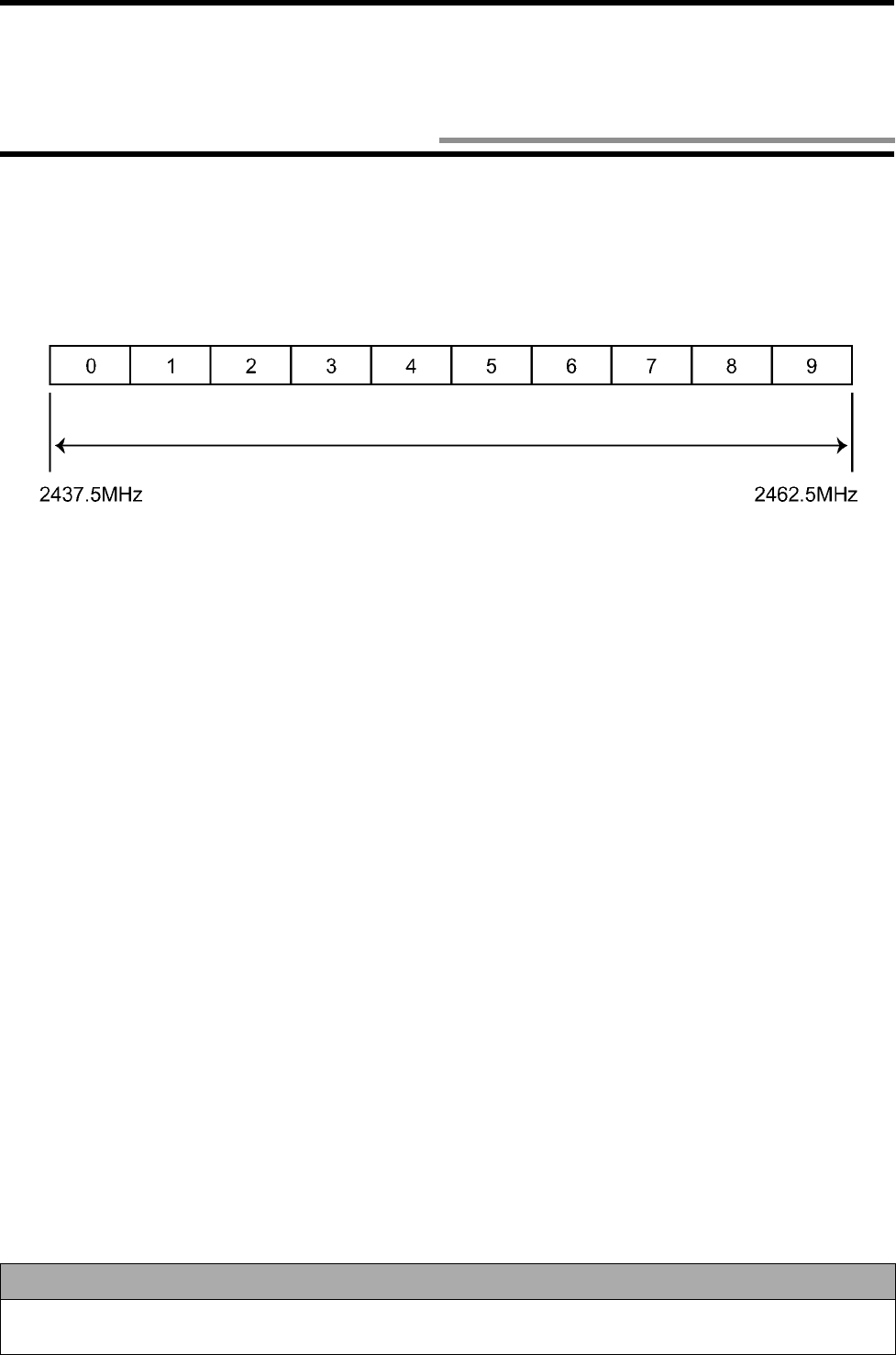
In this RFID system, a range from 2437.5 to 2462.5 MHz in the 2450 MHz frequency band can be divided into ten, and 10 channels (at
2.5-MHz intervals) are available. Those channels can be switched by a command from a host device. Use them to prevent the mutual
interference between antennas or interference caused by any other devices.
For the command, refer to Sections 5-9-2 and 5-9-3. The default value is Channel 5 (2450 MHz).
Correct Usage
Due to dispersion of frequency, the frequencies of adjacent channels may overlap each other. Do not assign consecu-
tive numbers to the channels of adjacent antennas.
Channel
2450 MHz frequency band
3-3 Radio Wave Channel Switching
3-4
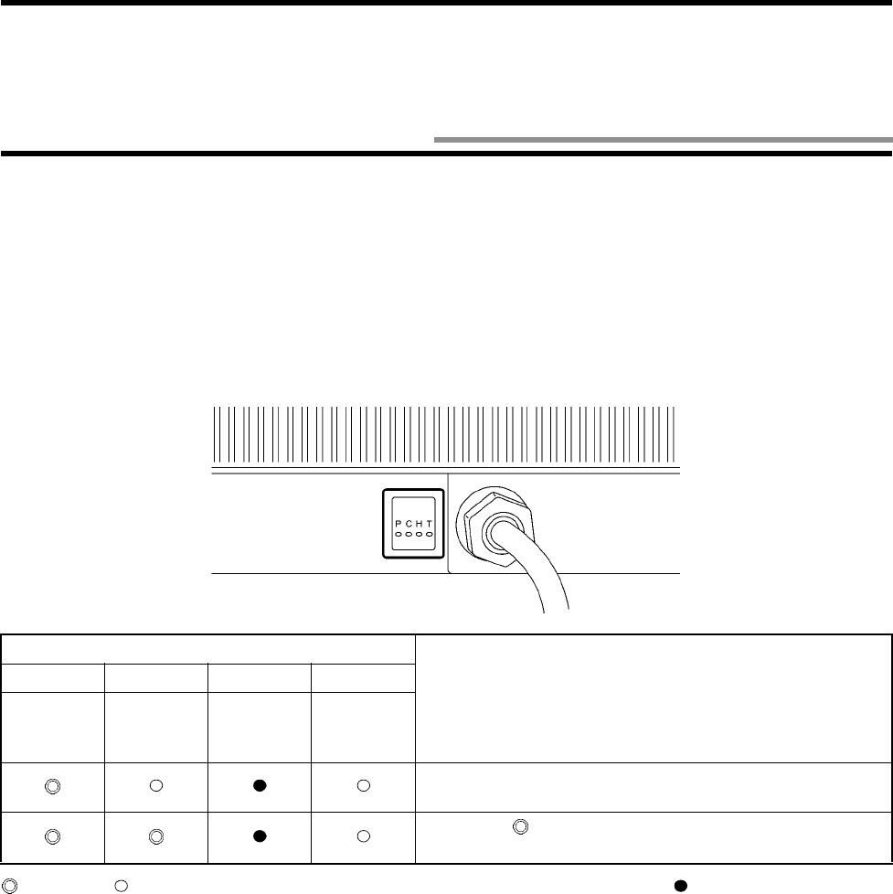
You can check the communication between an antenna and tag using the antenna only without connecting to a host device.
In the simplified communication test, the antenna detects the tag at approximately every 2 seconds and, if the tag responds, it turns on
the indicator C.
(1) Turn off the power supply.
(2) Short-circuit the setting terminals "+P" and "-P".
(3) Turn on the power supply. Then, the setting mode is enabled. (Refer to Section 5-1.)
(4) The simplified communication test starts. As shown below, the indicator C (Radio wave emission) shows whether the communica-
tion to the tag is made successfully.
(5) When any command has been sent from a host device to the antenna, the communication test stops.
: Turns on. : Blinks at approximately every 2 seconds. (This shows that data is being sent.) : Turns off.
Antenna Indicator (Red)
Indication
PCHT
Power
supply Radio
wave
emission
Host trans-
mission Tag trans-
mission
C and T blink at approximately every 2 seconds. This shows
that there is no tag.
C turns on ( ). This shows that there is a tag in the antenna
communication area.
3-4 Simplified Communication Test

3-5
Execute the communication test to check a radio wave environment at a working site.
Data (256 bytes) is communicated 256 times between the antenna and tag and the communication status is output. A total of 128 kbytes
of data is communicated in two ways. So, it takes a few seconds to execute this test. The communication is not retried. Refer to Section
5-7-8.
(1) Create a communication program at a host device.
(2) Enable the operation mode. (Disconnect the terminals "+P" and "-P" from each other. Refer to Section 5-1.)
(3) Turn on the power supply.
(4) Put the tag in front of the antenna.
(5) Send a communication test command (Section 5-7-8). If the antenna is 00, the command is [STX]0080T0SU[ETX].
(6) If the antenna responds to the host device, the communication between the host device and antenna has been made successfully.
(7) In the response [STX]8000T0000256 [ETX], a radio wave environment value is between 0000 and 0256. If the value is
close to 0000, the communication to the tag is stable.
Example of response from antenna:
* Radio wave environment is good.
[STX] 8 0 0 0 T 0 0 0 0 2 5 6 0 0 0 0 [ETX]
Number of Radio wave
communications environment value
* Radio wave environment is poor or no tag is in communication area.
[STX] 8 0 0 0 T 0 0 0 0 2 5 6 0 2 5 6 [ETX]
Number of Radio wave
communications environment value
Correct Usage
We recommend you to set the radio wave environment value to 50 or less.
3-5 Communication Test
3-6
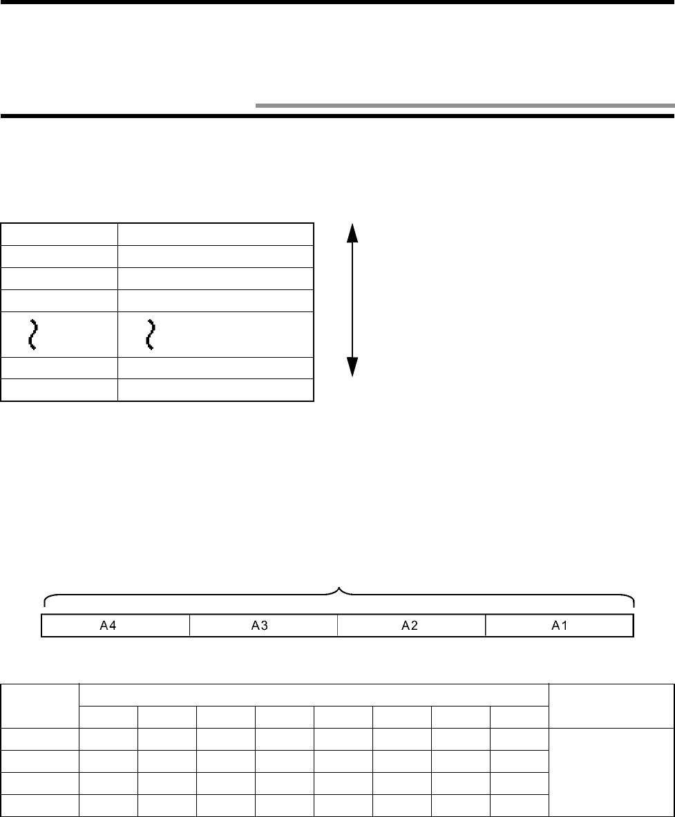
You can enable Write Protect for user data (8 kbytes) per page (256 bytes). Write Protect allows to prevent data being destroyed by
authorized writing.
♦
♦♦
♦Scope of Write Protect
The addresses of pages from P0 to P31 are described below.
* (h) means that the value is a hexadecimal number.
♦
♦♦
♦How to enable Write Protect
32 Bits of Write Protect data (4 bytes) of system data (refer to Section 2-2-3) correspond to each page. By rewriting a bit corresponding
to a write-protected page from 0 (disable) into 1 (enable), Write Protect to the page is enabled. To disable Write Protect, rewrite the bit
from 1 into 0.
Relation between bit of write-protected data and page is described below.
P**: Status of Write Protect in page ** (between 0 and 31).
Page 256 Bytes/page
P0 0000-00FF (h)
P1 0100-01FF (h)
P2 0200-02FF (h)
P30 1E00-1EFF (h)
P31 1F00-1FFF (h)
Code Bit Description
76543210
A1 P7 P6 P5 P4 P3 P2 P1 P0 Status of Write Pro-
tect
0: Disabled (Default
value)
1: Enabled
A2 P15 P14 P13 P12 P11 P10 P9 P8
A3 P23 P22 P21 P20 P19 P18 P17 P16
A4 P31 P30 P29 P28 P27 P26 P25 P24
Write-Protected Data (4 Bytes)
3-6 Write Protect Function
256 Bytes x 32 pages =
8192 bytes
3-6 Write Protect Function
3-7
♦
♦♦
♦Example of enabling/disabling Write Protect
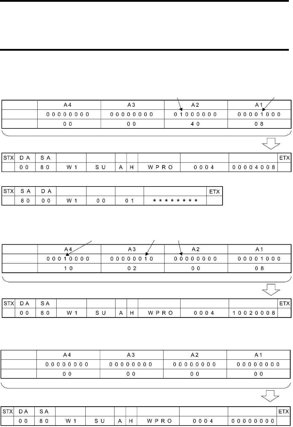
(1) Enable Write Protect to P3 and P14 in the initial state of the ID tag.
Write-protected data is as follows:
(2) Disable Write Protect to P14, which was enabled in the step (1), and enable Write Protect to P17 and P28.
Write-protected data is as follows:
(3) Disable any Write Protect to any page.
Write-protected data is as follows:
Enables Write Protect to P14 Enables Write Protect to P3
Decimal notation
An example of the Write command (Section 5-7-4) is as follows:
Hexadecimal
notation
Command code
Communication
designation Split
flag
Data desig-
nation
Start address
Number of written bytes
Written data
Termination code
Response number
ID code
Response from the antenna at the normal end is as follows:
Command code
Enables Write Protect to P17 Disables Write Protect to P14
An example of the Write command (Section 5-7-4) is as follows:
Enables Write Protect to P28
Command code
Communication
designation Split
flag
Data desig-
nation
Start address
Number of written bytes
Written data
Decimal notation
Hexadecimal
notation
A
n example of the Write command (Section 5-7-4) is as follows:
Command code
Communication
designation Split
flag
Data desig-
nation
Start address
Number of written bytes
Written data
Decimal notation
Hexadecimal
notation
3-8
The tag has the two power-saving functions below.
♦
♦♦
♦Function to prevent battery power loss due to radio wave emitted from any other radio
equipment (Enabled always)
If any radio equipment is located near a tag, the tag operates (ready to operate) because the tag’s receiving band is wide. As a result, the
tag battery may be consumed. (Refer to "Notes on Interference to Second-Generation Low-Power Data Communication System (Wire-
less LAN), Cellular Phone, etc." at the beginning of this manual.)
To prevent this power loss, the tag has a function to enter a sleep state (refer to "Appendix 1 - Glossary") against a radio wave emitted
from any other radio equipment.
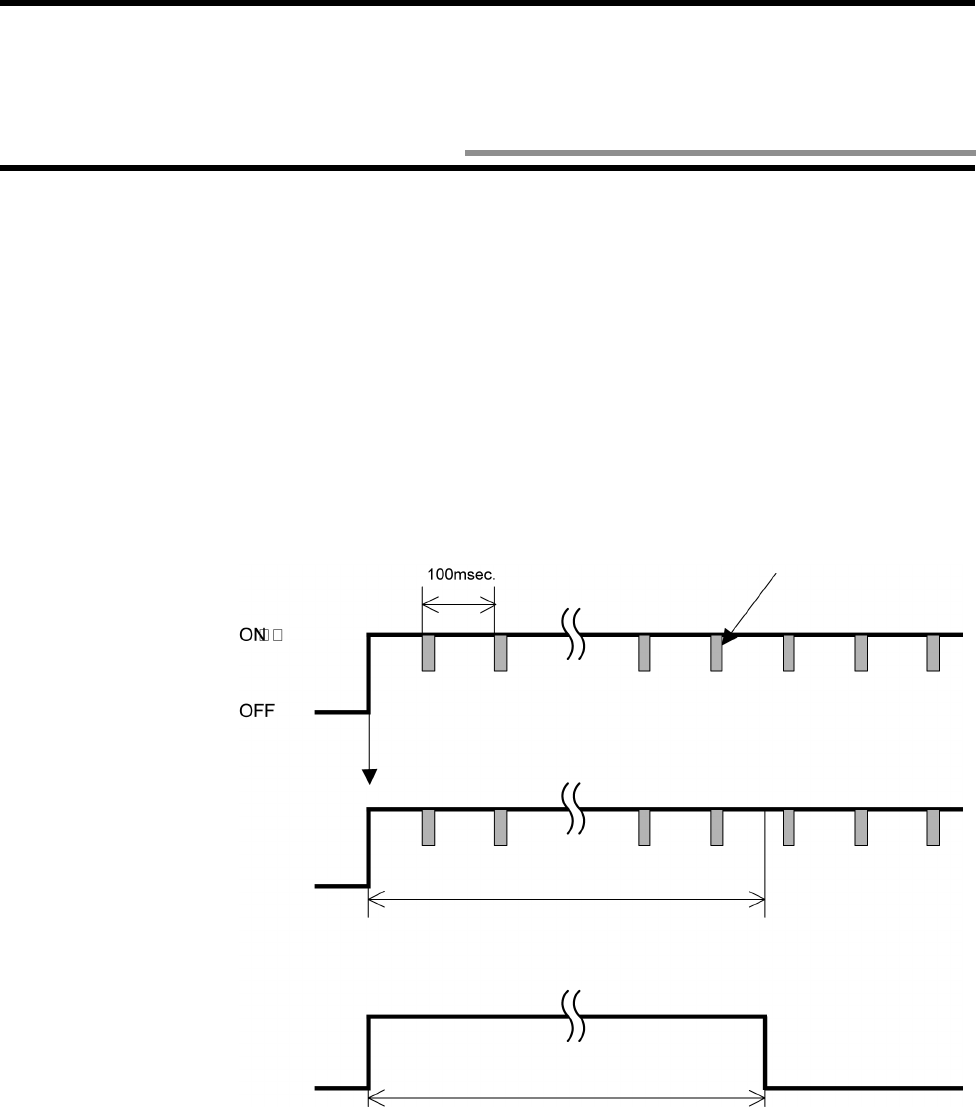
• The V690 antenna sends a wake instruction (refer to "Appendix 1 - Glossary") at every 100 msec after emitting a radio wave and the
tag operates (ready to operate).
• When the tag receives a radio wave emitted from any other radio equipment, the tag may operate (ready to operate). However, unless
receiving a valid wake instruction, the tag returns to a sleep state in 2 seconds.
Antenna radio wave emission
Wake instruction
Even if there is no command from a host device, the antenna sends a wake
instruction at every 100 msec while emitting a radio wave.
Tag
Operates (Ready to operate)
Sleep 2 seconds (fixed)
If the tag once receives a valid wake instruction in 2 sec-
onds after it started an operation, the tag does not sleep.
Tag
Operates (Ready to operate)
Sleep 2 seconds (fixed)
If the tag cannot receive a valid wake instruction in 2 sec-
onds after it started an operation, the tag sleeps.
3-7 ID Tag Power-Saving Function
3-7 ID Tag Power-Saving Function
3-9
♦
♦♦
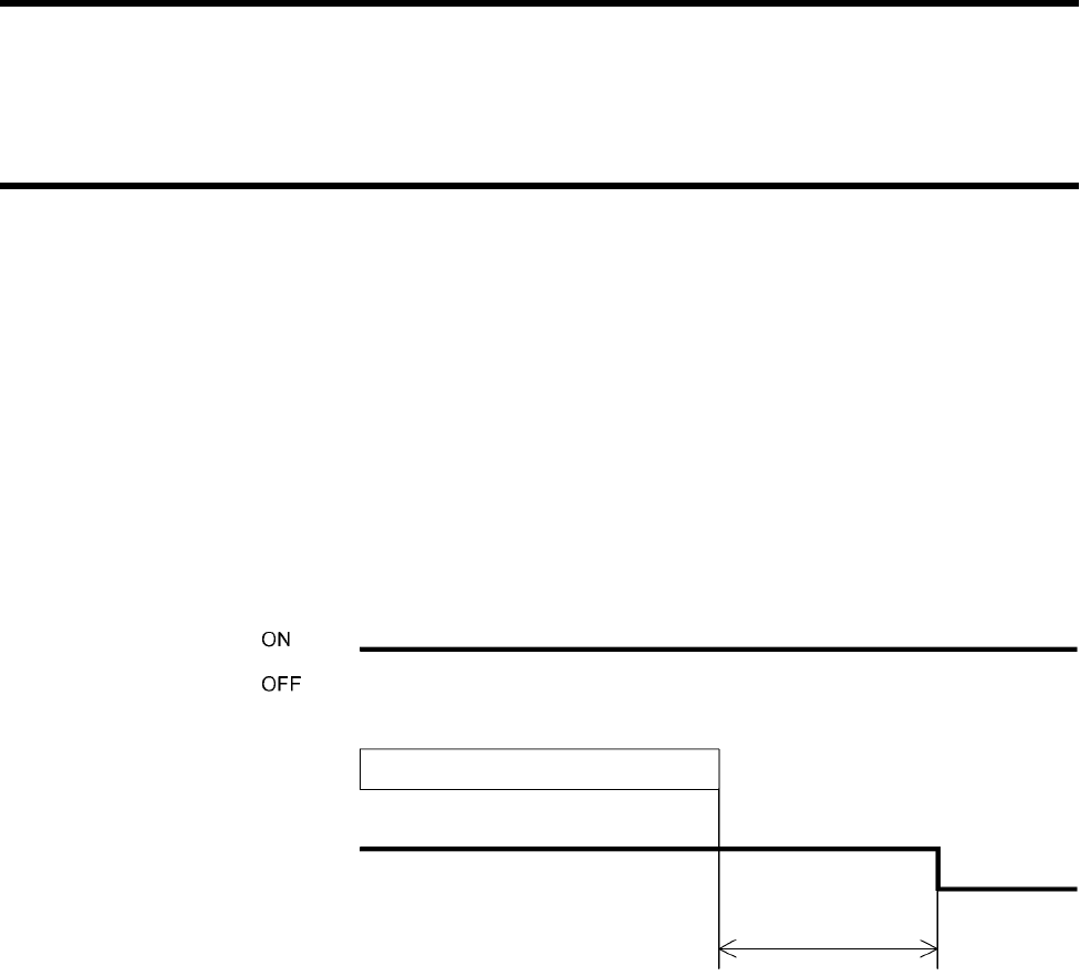
♦Function to prevent battery power loss due to neglect when tag works (Enabled always)
When you use the antenna with a repeat command (refer to (3) in Section 5-2-1), due to a trouble in a working site, the tag may be left
in front of the antenna which is emitting a radio wave, although the tag operates (ready to operate). Then, the tag battery is consumed.
To prevent this power loss, the tag has a function to enter a sleep state when a waiting time for sleep (refer to a chart below) has passed.
If the tag cannot receive a valid command within a waiting time for sleep after receiving a valid command, the tag enters a sleep state.
A default value of waiting time for sleep is 480 seconds (8 minutes). To change waiting time, specify "SLEP" as address in the Read/
Write command. (Refer to Sections 5-7-1 and 5-7-3 to 5-7-5.)
To recover the tag from the sleep state:
• Turn OFF the power supply transmission of the antenna and turn ON it again.
• Take the tag out of the communication area and place it in the communication area again.
Antenna radio wave emission
Tag Operates (Ready to operate)
Sleep
(A radio wave is being emitted)
Command process
Waiting time for sleep

4-1
4-1-1 Installation Environment
(1) Antenna and tag
Install the antenna and tag so that those front faces can face each other. Confirm the front side and the reverse side of them. The front
faces must face each other.
(2) Antennas
Keep sufficient space between the antennas according to Section 7-5. If sufficient space cannot be obtained:
• Assign the most different channel numbers to the radio channels of adjacent antennas. (Refer to Section 3-3.)
• Permit only one of antennas to transmit a radio wave so that those antennas do not transmit radio waves simultaneously.
(3) Tag rotating position to antenna
The antenna and tag use "circularly polarized wave" as radio wave to communicate with each other. So, the tag can communicate with
the antenna at any rotating angle.
The maximum communication range varies depending on the rotating angle of the tag. Refer to Section 7-3.
• Conceptual diagram of circularly polarized wave
The arrows show the directions of vibrating surface. The radio wave propagates while the vibrating surface is rotating.
Antenna Tag
Front face
Front face
Antenna
Tag
* A hatched area on the tag shows the "omron" logo.
Chapter 4 Installation and Connection
4-1 Read/Write Antenna and ID Tag
4-1 Read/Write Antenna and ID Tag
4-2
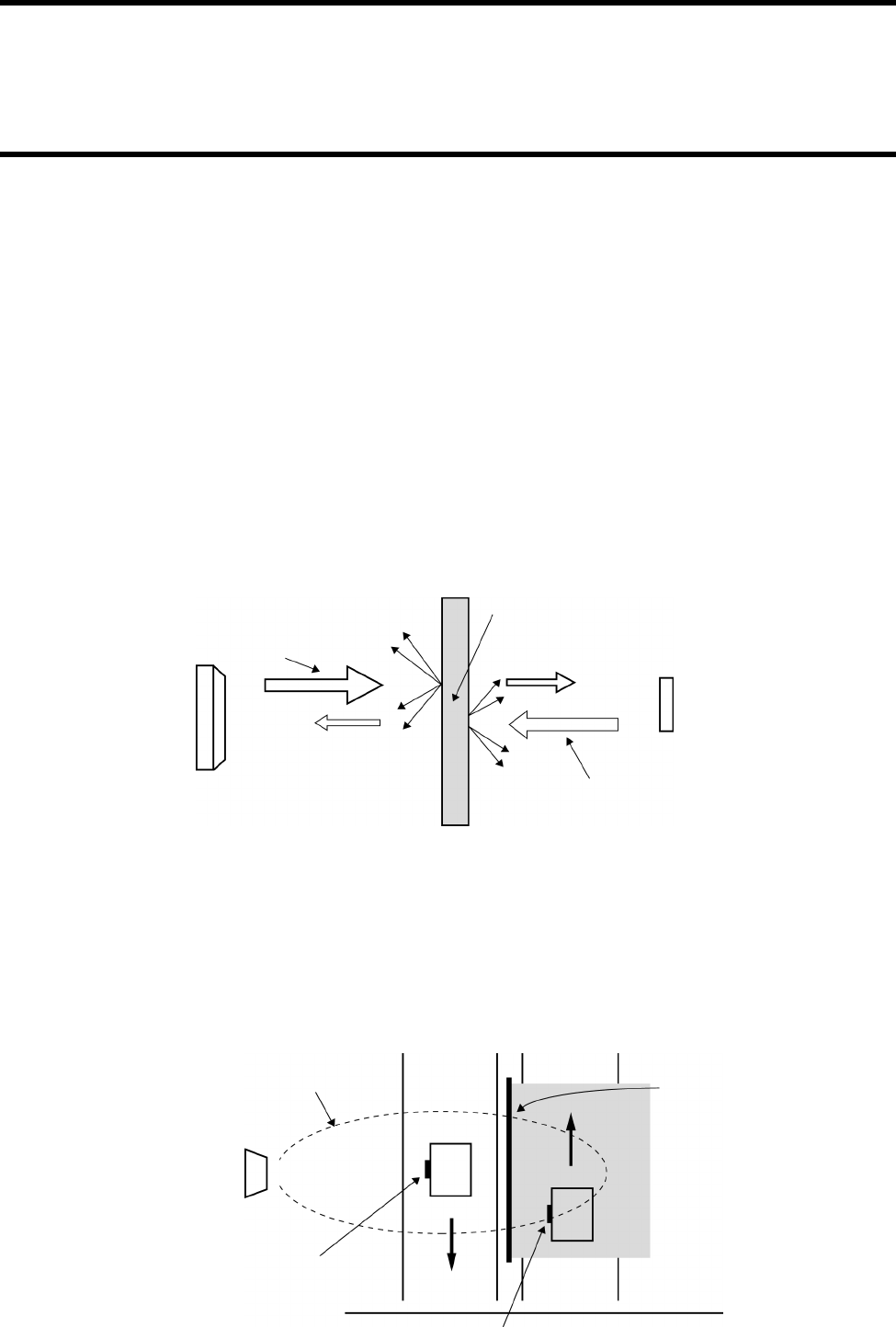
(4) Influence of external objects
• Radio wave absorbers: water, human body, water screen, water-absorptive material, etc.
A radio wave (microwave) penetrates anything (solid body and liquid) other than metal, but it is attenuated while penetrating. In partic-
ular, water absorbs a radio wave extremely. When a radio wave penetrates the water, the radio wave is absorbed considerably. Also, the
radio wave is attenuated remarkably in a human body which contains much water. So, any solid body and liquid must not exist between
the antenna and tag.
A general-purpose plastic plate with thickness of or glass plate a few millimeters does not absorb the radio wave, and the radio wave
attenuation is not a serious problem in this case. However, the radio wave attenuation varies depending on a type of material and/or
thickness of external objects which the radio wave penetrates. Execute the communication experiment in a working site in advance.
When the communication is performed through the plastic plate or glass plate which absorbs the radio wave so much, such plastic plate
or glass plate may be covered with water due to rain. The radio wave may be attenuated by this water screen and the communication
may fail. Execute the communication experiment in a working site in advance and take great care not to get out of the communication
range during an operation.
Dry wood and paper do not attenuate the radio wave so much. However, wood and paper absorb water easily. The wet wood and paper
may attenuate the radio wave considerably. Execute the communication experiment in a working site in advance using both of dry
materials and wet ones.
• Radio wave reflectors: metal, ground, etc.
Metal reflects a radio wave (microwave) like a mirror reflects light. If there is a metal near an antenna communication area, the commu-
nication area is affected by the metal. If a metal is put between an antenna and tag, the communication between the antenna and tag may
fail. Metal, whether metal plate or wire netting, may affect the communication. Also, the ground affects the communication like metal.
As shown below, a radio wave absorber or reflector can be used to interrupt a radio wave. When you interrupt the radio wave, execute
the communication experiment in a working site in advance.
Example of radio wave absorber: ECCOSORB AN75 (61 x 61 cm, E&C Engineering)
Radio wave transmitted
from an antenna
A part of radio wave
is reflected.
Object Absorbed in an object and attenuated.
Tag
Radio wave transmitted
from a tag.
Outgoing
Incoming
Antenna
Communication
area
Tag that you want to
process data
Tag that you do not want to process data
Radio wave interrupt
4-1 Read/Write Antenna and ID Tag
4-3
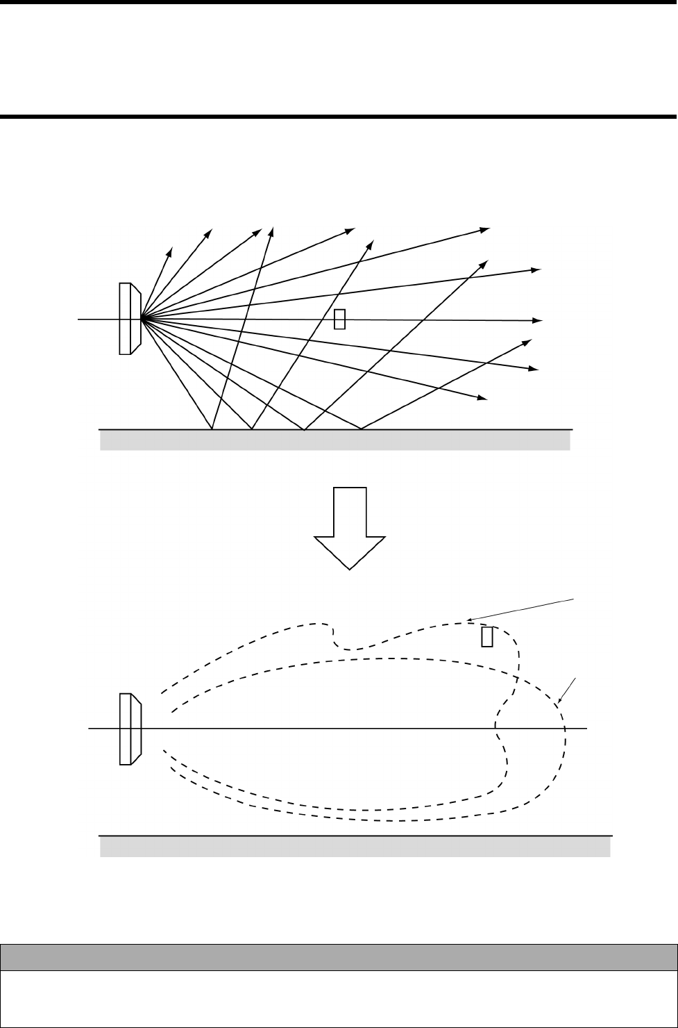
• Communication area affected by the ground
If an antenna is installed near the ground, radio waves (microwave) emitted from the antenna and ones reflected by the ground overlap
each other. Therefore, an outline of the communication area becomes ragged and complex. In this case, dead zones may be formed fre-
quently, where no communication can be made to the tag.
Correct Usage
Depending on a working site, a special point may be generated in the communication area above and the communica-
tion to the tag cannot be made at the point. So, be sure to execute the communication check with a communication test
(refer to Section 3-5), etc.
Antenna
Tag
Ground
Tag
Antenna
Ground
Communication area affected by the ground
Communication area not
affected by the ground
4-1 Read/Write Antenna and ID Tag
4-4
(5) Installation environment
Do not install the antenna and tag at any place below:
• Place where the ambient temperature is out of the range between -20 and +60°C for the antenna and -25 and +70°C for the tag, where
the temperature fluctuates considerably and where moisture condensation occurs frequently.
• Place where the relative humidity is out of the range between 35 and 85%RH.
• Place where there is corrosive gas, flammable gas, dust, salt or iron powder.
• Place affected by vibration or impact.
• Place splashed with water, oil or chemicals
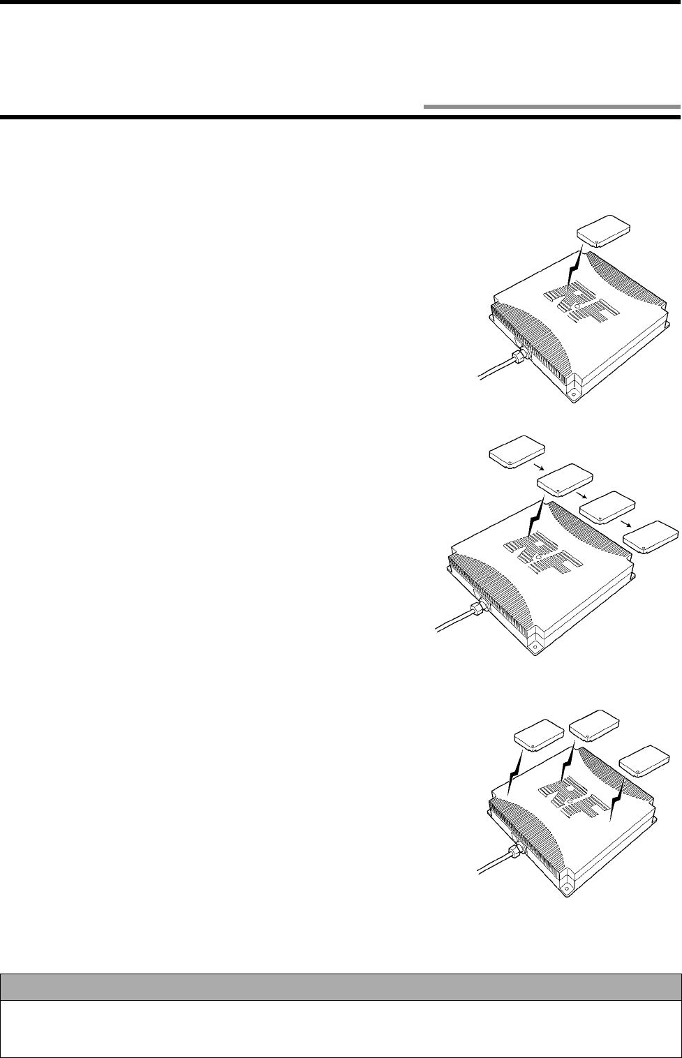
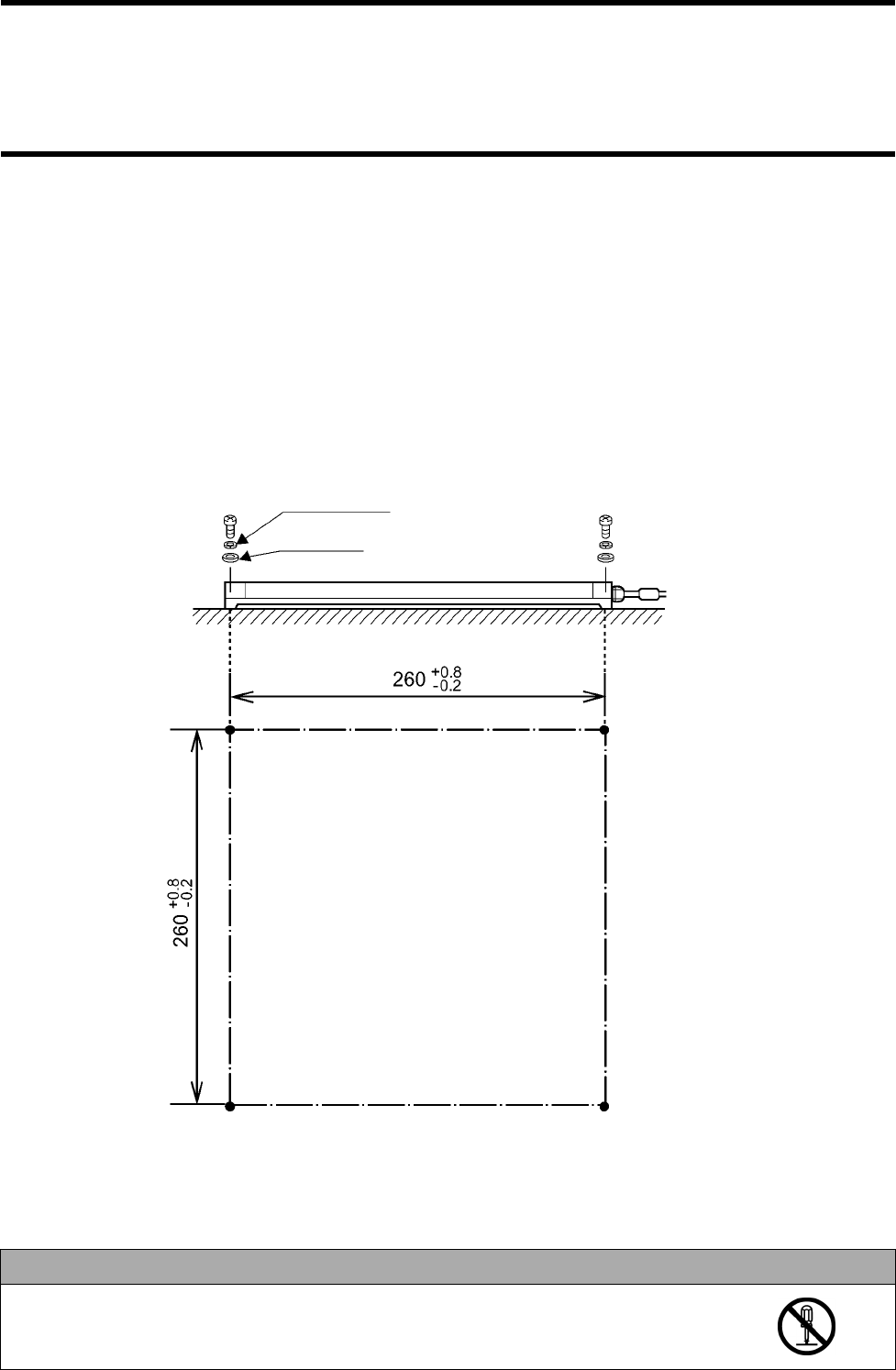
4-1-2 How to Install Antenna
Install an antenna on a flat plane taking care not to bend it by force. As shown below, mount the antenna with four M5 screws, spring
washers and flat washers. Tightening torque is 2.0 N•m (approximately 20 kgf•cm). Do not use any lock paint to fix screws.
Correct Usage
Do not disassemble it nor touch the inside when the power supply turns on. Otherwise, trouble
may be caused.
Spring washer
Flat washer
(Unit: mm)
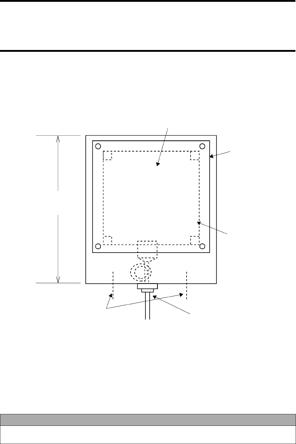
4-1 Read/Write Antenna and ID Tag
4-5
4-1-3 Rainproofing of Antenna
The antenna is not waterproof structure. So, do not install the antenna.
If you must install the antenna outdoors, protect the antenna against rain with a plastic rainproof box. To prevent the water droplet com-
ing in the antenna through a cable, be sure to turn the antenna cable section downward.
Example of plastic rainproof box: Model WB-5AJ (Outside dimensions: 571 (H) x 412 (W) x 210 (D) mm, Mirai Industry)
Correct Usage
Protective structure IP62 of the antenna is the protection against the drop of water. If the antenna is splashed with water
spray or water jet flow, cover the antenna with a protection plate. (Refer to "Appendix 3 - Protective Structure".)
Gap between the antenna surface and window plate is 10 to 20 mm.
Size enough to cover
the entire antenna
including a connector.
Example of protection box
Drill a large hole for ventilation
and drainage. Clamp it to prevent the connector
being pulled directly.
If the box is metallic, make
a window on the box. The
window size shall be the
same as the antenna.
Cover the window with an
acrylic plate, etc. 3 mm in
thickness which a radio wave
can penetrate easily.
4-1 Read/Write Antenna and ID Tag
4-6
4-1-4 How to Install Tag
♦
♦♦
♦Installation
Install a tag on a flat plane taking care not to bend it by force. As shown below, mount the antenna with two M4 screws, spring washers
and flat washers. Tightening torque is 1.2 N•m (approximately 12 kgf•cm). Do not use any lock paint to fix screws.
♦
♦♦
♦Influence on communication performance, adhesive, metal tape, water screen, etc.
• When you apply adhesive, etc. on the tag surface, a radio wave (microwave) is attenuated and the communication area may be
affected. Execute the communication experiment with anything used actually in advance.
• If a metallic tape, etc. is put on the tag surface, a radio wave is interrupted and the communication to the antenna fails.
• If the tag is put on a glass plate with double-sided adhesive tape as shown below, a gap between the glass plate and tag sweats easily.
Moreover, a water screen may be generated. In this case, please note that a radio wave is absorbed and the communication range
may become small.
Spring washer
Flat washer
(Unit: mm)
Glass plate, etc.
ID tag
Double-sided adhesive tape, etc.
4-1 Read/Write Antenna and ID Tag
4-7
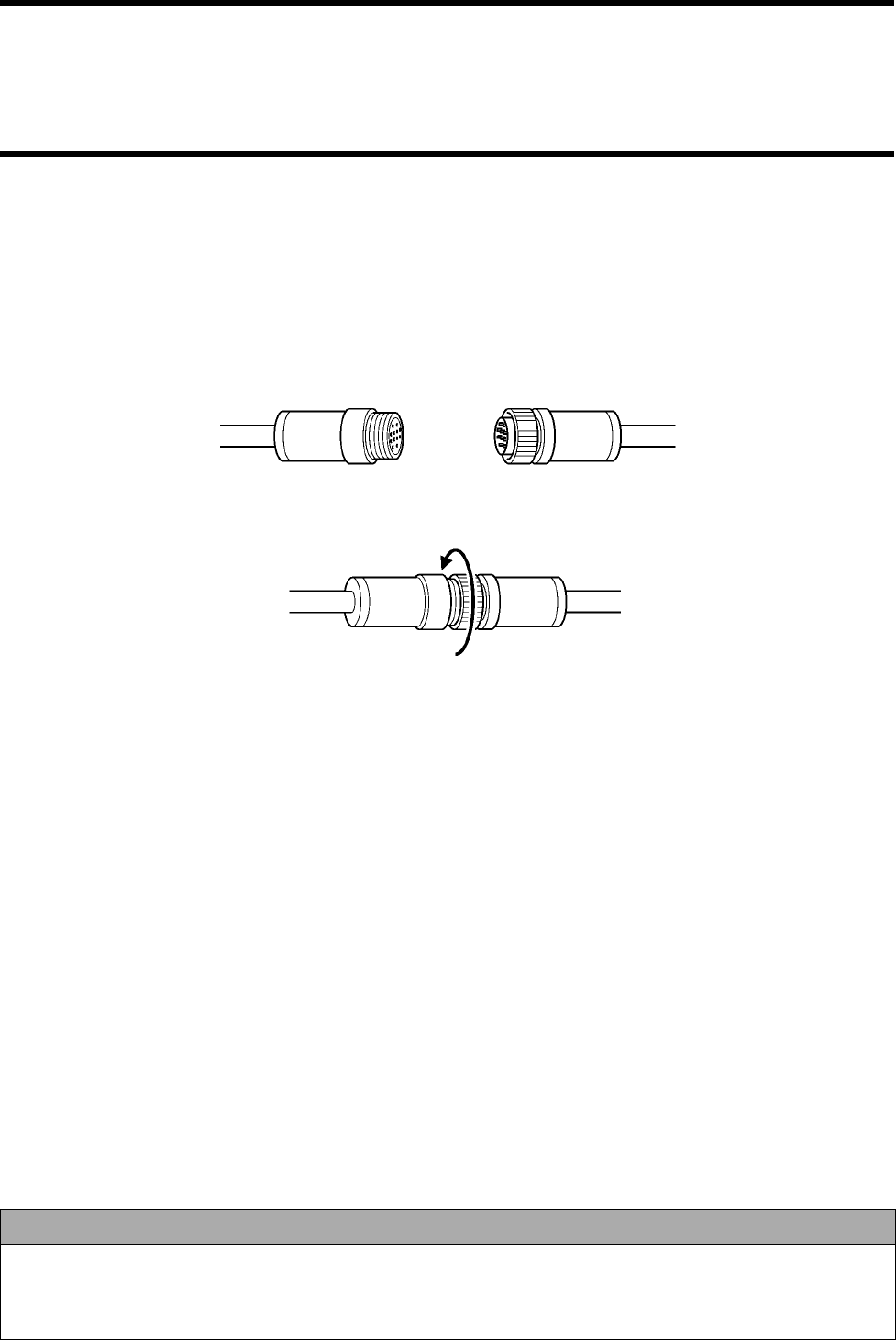
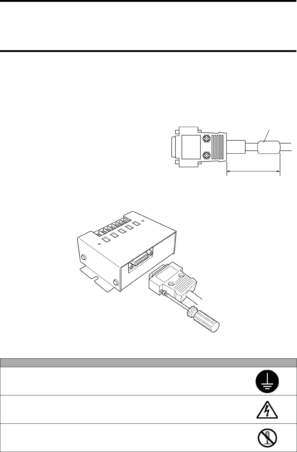
4-1-5 How to Connect Connecting Cable to Antenna
To connect an antenna and host device, use a connecting cable (unbundled).
RS-232C connecting cable V690-A4! * Refer to Section 2-4.
RS-422A/485 link unit connecting cable V690-A5! * Refer to Section 2-4.
(1) When you connect a connector of dedicated cable and connector of antenna, be sure to hold those connectors and insert them into
each other completely.
(2) When you have connected the connectors, turn a ring completely as shown below.
Correct Usage
• Do not connect nor disconnect the connectors when the power supply turns on. Otherwise, a trouble is caused.
• Do not pull the cable by force.
• Do not touch a connecting terminal of the connector.
• Do not touch the connector during an operation.
Dedicated cable Antenna side
Ring
4-8
4-2-1 How to Wire RS-232C Interface
(1) Using RS-232C connecting cable
To connect an antenna and IBM PC compatible machine, use a dedicated RS-232C connecting cable model V690-A4!. Connect the
five electric wires at a connector of host device as shown below.
Connection of leader line of RS-232C connecting cable
Leader line of connecting cable Details of connection
Brown Thick wire of AWG22 (+) of 24 VDC power supply
Blue (-) of 24 VDC power supply
Light green Thin wire of AWG26
"+P" and "-P" for the setting mode: Not connected for the operation mode.
Short-circuited for the setting mode.
Black
Green/Yellow Thick wire of AWG22 Ground according to Class D.
Pin
No.
IBM PC Compatible
Machine
RS-232C Connecting Cable
Model V690-A4!
!!
!
Socket (Male) Plug (Female)
1
2 RD (Receiving) TX (Sending)
3 SD (Sending) RX (Receiving)
4
5
SG (Grounding for signal) SG (Grounding for signal)
6
7 RS (Request to send)
Loop back (Short-circuit)
8 CS (Clear to send)
9
IBM PC compatible
machine
RS-232C connecting cable (Model V690-A4!)
•
• •
• Recommendable DC 24 power supply
Model S82K-01524 (Output: 24 VDC, 0.6 A. Input: 100 to 240 VAC.
OMRON)
Grounding
according
to Class D
Switch,
etc.
24 VDC
power
supply
Antenna
Model V690-HMG01
4-2 How to Wire to Host Device
Connector pin layout
View of fitting face
4-2 How to Wire to Host Device
4-9
(2) Using RS-232C connecting cable to extend a cable and connecting to IBM PC compatible machine (typical)
To connect an IBM PC compatible machine (typical) extending a dedicated RS-232C connecting cable, prepare the cables shown below.
Thickness of wire in the cable must be AWG26 or more.
•
••
•Recommendable 24 VDC power supply
Model S82K-01524 (Output: 24 VDC, 0.6 A. Input: 100 to 240 VAC. OMRON)
If you do not use the recommendable power supply or equivalent, connect to the 24 VDC power supply via a line filter type GT-205J
(Tokin) or equivalent.
IBM PC compatible
machine
RS-232C connecting cable (Model V690-A4!)
Grounding
according
to Class D
Switch,
etc.
DC 24 V
power
supply
Cable prepared by you
Pin No.
IBM PC Compatible Machine
(Typical) Cable prepared by you
Socket (Male)
RS-232C Connecting Cable
Model V690-A4!
Plug (Female)
Female
Male
RD (Receiving)
SD (Sending)
RS (Request to send)
CS (Clear to send)
SG (Grounding for signal)
TX (Sending)
RX (Receiving)
SG (Grounding for signal)
Loop back
4-2 How to Wire to Host Device
4-10
(3) Connecting to OMRON PLC
To connect an antenna and OMRON programmable controller (PLC), prepare a dedicated RS-232C connecting cable model V690-A4!
and connected cable.
Thickness of wire in the cable must be AWG26 or more.
Pin No. OMRON PLC Cable prepared by you
Socket (Female)
RS-232C Connecting Cable
Plug (Female)
Male
Female
RD (Receiving)
SD (Sending)
RS (Request to send)
CS (Clear to send)
SG (Grounding for signal)
TX (Sending)
RX (Receiving)
SG (Grounding for signal)
Loop back
OMRON PLC
RS-232C connecting cable (Model V690-A!)
Grounding
according
to Class D
Switch,
etc.
24 VDC
power
supply
Cable prepared by you
Loop back
(Short-circuit)

4-2 How to Wire to Host Device
4-11
4-2-2 How to Wire When Connecting RS-422A/485
(1) 1:1 connection with link unit
To connect an antenna and host device through RS-422A/485, use the link unit. An example below shows the connection of one
antenna and one host device through RS-422A (4-wire).
Microwave
antenna
Station No.
00
Link unit
RS-422A/485 link unit connecting cable
Host device
24 VDC
ground-
ing
Host device
setting
* RS-422A
(4-wire)
* Terminating
resistance
RD ON
SD ON
Link unit set-
ting
* RS-422A
(4-wire)
* Terminating
resistance
RD ON
SD ON
4-2 How to Wire to Host Device
4-12
Internal configuration of the 1:1 connection of an antenna and host device through RS-422A (4-wire) is shown below.
• Signal lines (Rx, Tx and SG) of RS-232C are disconnected.
• If RS-422A is selected with the link unit, SD and RD of the terminating resistance (220 Ω) can be turned ON/OFF.
Microwave
antenna
Station No. 00
Link unit
RS-422A/485 link
unit connecting
cable
Power sup-
ply circuit
Setting
mode
Antenna
RS-422A circuit
RS-232C circuit
Grounding
Cut in a connector.
Antenna
power
supply
switch Setting switch
Link unit
When switching
RS-422A
4-2 How to Wire to Host Device
4-13
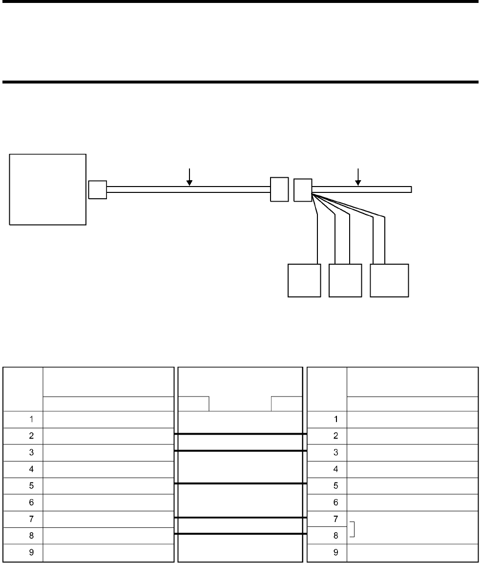
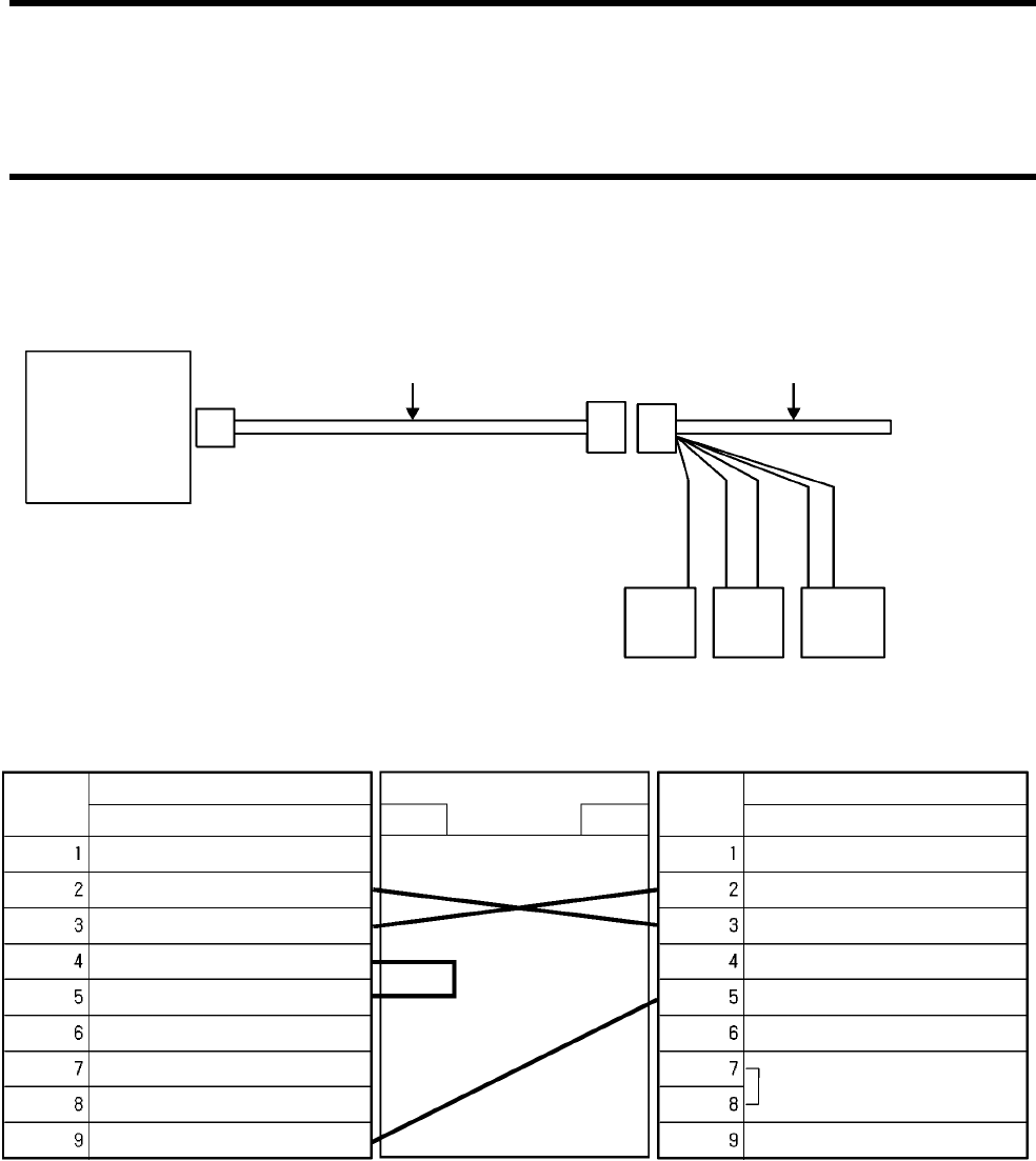
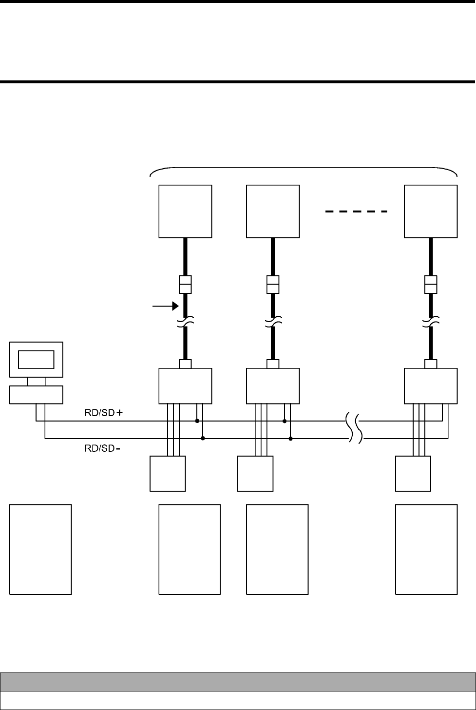
(2) 1:N connection with link unit
To connect an antenna and host device through RS-422A/485, use the link unit. An example below shows the connection of several
antennas and one host device through RS-485 (2-wire).
Correct Usage
Turn ON (connected) the terminating resistances at both ends of the entire RS-422A/RS-485 communication wiring.
Microwave
antenna
Station No.
00
Link unit
RS-422A/485 link unit
connecting cable
Host device
24 VDC
ground-
ing
Host device set-
ting
* RS-485
(2-wire)
* Terminating
resistance ON
Link unit setting
* RS-485
(2-wire)
* Terminating
resistance
OFF
Microwave
antenna
Station No.
01
Microwave
antenna
Station No.
31
24 VDC
ground-
ing
24 VDC
ground-
ing
Link unit Link unit
Link unit setting
* RS-485
(2-wire)
* Terminating
resistance
OFF
Host device set-
ting
* RS-485
(2-wire)
* Terminating
resistance ON
A maximum of 32 units can be connected

4-2 How to Wire to Host Device
4-14
Correct Usage
A host device must send the next command in 10 ms after checking a response from an antenna. When you use an RS-
232C/485 converter, etc. in the host device, the command must be sent after the command transmission has been
enabled completely. When the command has been sent completely, switch into the receiving state within 10 ms. Other-
wise, the communication with the antenna may fail.
Host device
Command frame
(1st time)
Read/Write antenna
Model V690-HMG01 Response frame
Command frame
(2nd time)
4-2 How to Wire to Host Device
4-15
Internal configuration of the 1:N connection of an antenna and host device through RS-485 (2-wire) is shown below.
• Signal lines (Rx, Tx and SG) of RS-232C are disconnected.
• If RS-485 is selected with the link unit, the terminating resistance (220 Ω) can be turned ON/OFF.
Microwave
antenna
Station No. 00
Link unit
RS-422A/485 link
unit connecting
cable
Power sup-
ply circuit
Setting
mode
Antenna
RS-422A circuit
RS-232C circuit
Cut in a connector.
Antenna
power
supply
switch Setting switch
Link unit
When switching
RS-485
Grounding
4-16
4-3-1 Installation Environment
♦
♦♦
♦Installation site
Do not install the link unit at any place below:
• Place where the ambient temperature is out of the range between 0 and +55°C, where the temperature fluctuates considerably and
where moisture condensation occurs frequently.
• Place where the relative humidity is out of the range between 35 and 85%RH.
• Place where there is corrosive gas, flammable gas, dust, salt or iron powder.
• Place affected by vibration or impact.
• Place splashed with water, oil or chemicals
♦
♦♦
♦Assembly in panel
The ambient operating temperature of link unit is between 0 and +55°C. The following conditions must be met.
• Provide sufficient space for ventilation.
• Do not install the controller near by any heating sources (heater, transformer and large-sized resistance).
• If the ambient temperature rises to 55°C or more, install a ventilating fan or air conditioner to keep the temperature at 55°C or less.
• If you wire a power line (for high current to drive a motor) near the controller, execute the communication experiment fully to check
the influence of noise and wire it with care.
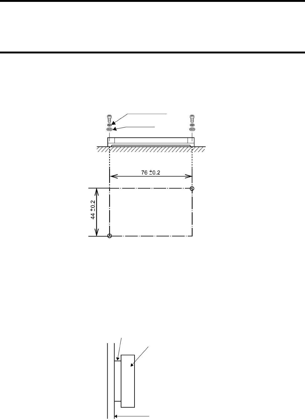
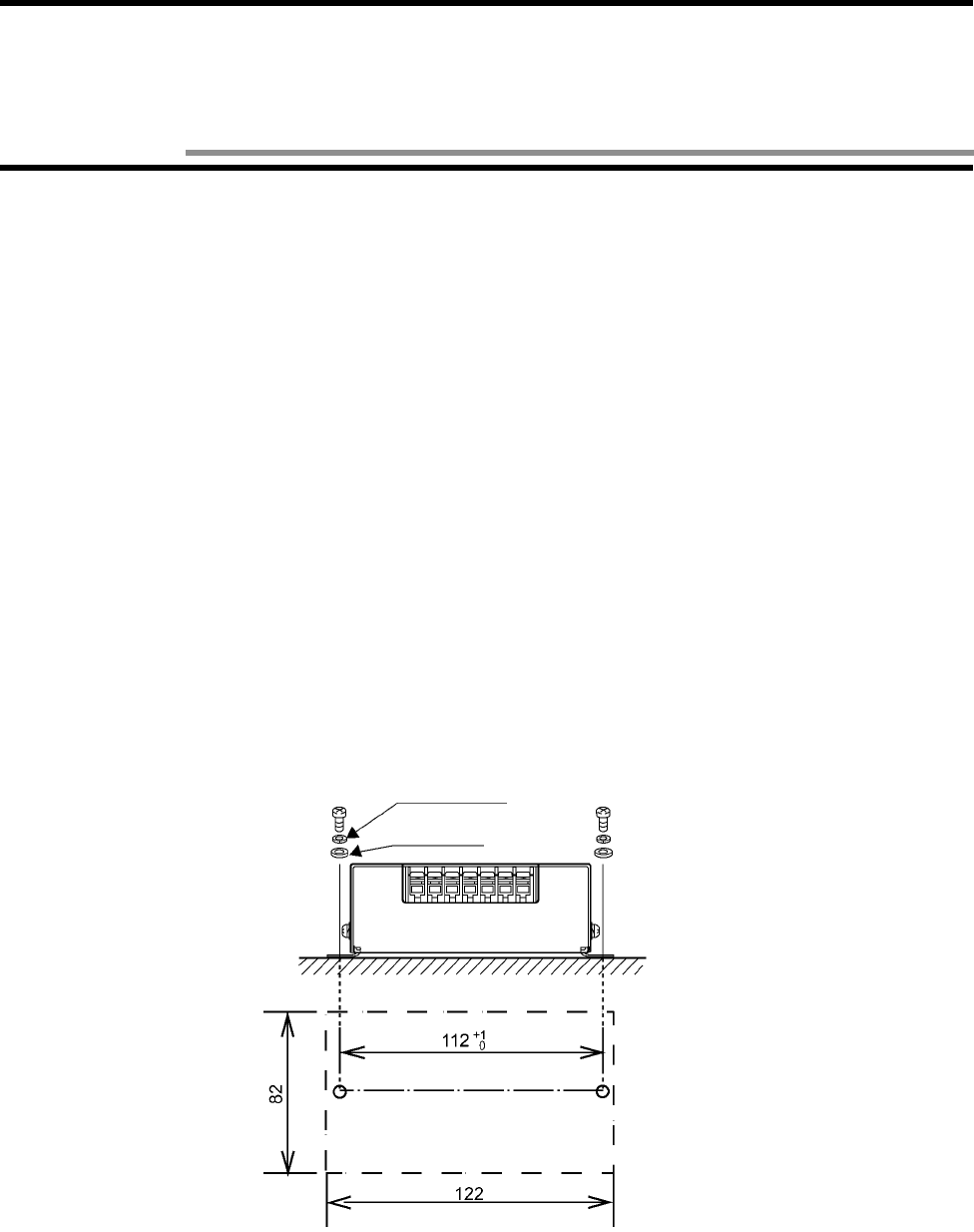
4-3-2 How to Install
Install a link unit on a flat plane taking care not to bend it by force. As shown below, mount the antenna with two M4 screws, spring
washers and flat washers. Tightening torque is 1.2 N•m (approximately 12 kgf•cm).
Spring washer
Flat washer
(Unit: mm)
4-3 Link Unit
4-3 Link Unit
4-17
4-3-3 How to Wire
♦
♦♦
♦Connecting RS-422A/485 link unit connecting cable
To connect:
(1) When you connect a connector of dedicated cable to the link unit, be sure to hold the connector and insert it into the link unit com-
pletely.
(2) When you have inserted the cable into the link unit, tighten the two lock screws with the Phillips type screwdriver to fix it.
(3) Fit the connecting cable with a supplied ferrite core. Close the ferrite core and lock it completely.
To disconnect:
(1) To disconnect the connector, loosen the two lock screws completely and pull out it straight holding the connector hood lug.
(2) If it is hard to pull out, push the link unit pulling out the connector.
Correct Usage
Be sure to connect a grounding wire. Otherwise, an error may occur in an operation.
Do not touch any terminal when the power supply turns on. Otherwise, an error may occur in an
operation.
Do not disassemble it nor touch the inside when the power supply turns on. Otherwise, trouble
may be caused.
Ferrite core
Within 10 cm
4-3 Link Unit
4-18
♦
♦♦
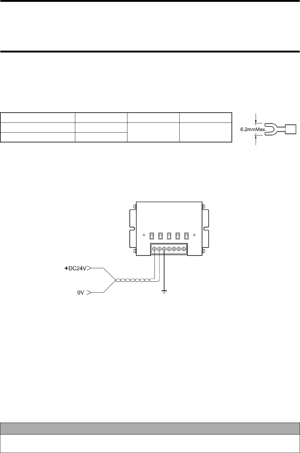
♦Connecting power supply wire, grounding wire and signal wire
M3 screws are used for the power supply, grounding and signal terminals. For a crimp terminal, use any of terminals below. Tightening
torque is 0.6 N•m (approximately 6 kgf•cm).
•
••
•Applicable crimp terminal
•
••
•Recommendable 24 VDC power supply
Model S82K-01524 (Output: 24 VDC, 0.6 A. Input: 100 to 240 VAC. OMRON)
•
••
•Be sure to ground GR according to the Class D.
Manufacturer Model Applicable Wire Type
Japan Solderless Terminal 1.25-B3A AWG22 to
AWG16 Fork
Japan Solderless Terminal 1.25-C3A
Correct Usage
If any noise superposed on the power supply line is large, supply the power through a line filter. Then, ground noise can
be reduced considerably. Example of line filter: Model GT-205J (Tokin).
(Example of connection)
Grounding according to Class D
(For M3)
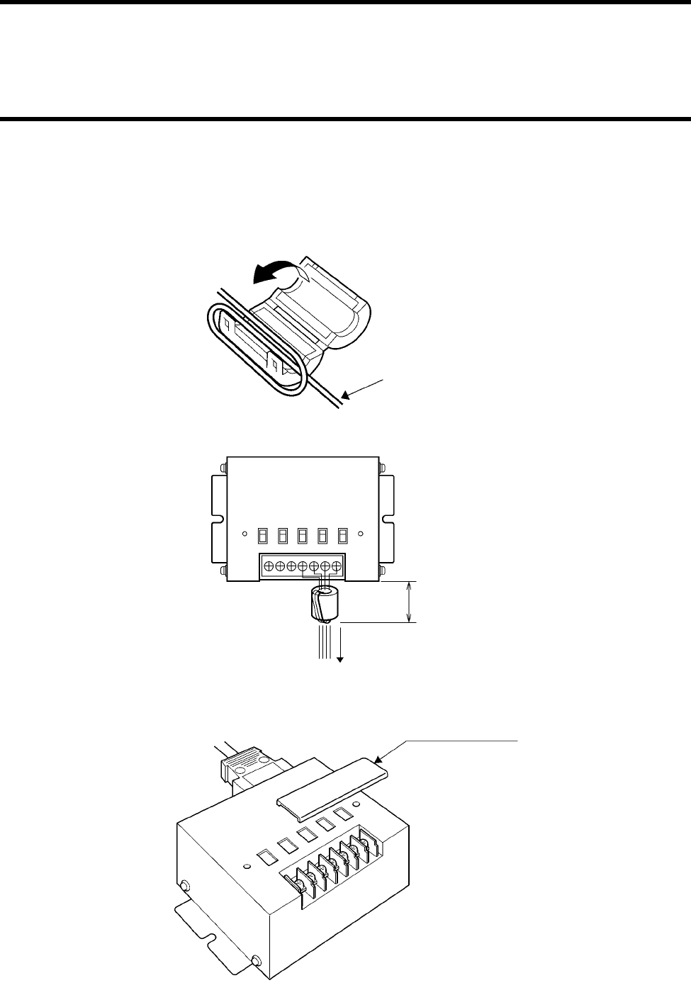
4-3 Link Unit
4-19
♦
♦♦
♦Connecting signal wire
To suppress noise, fit a signal line with a supplied ferrite core as shown below.
(1) Wire the signal wires.
(2) Put the signal wires together and wind the signal wire round the ferrite core. As shown below, wind the signal wire once to prevent
the ferrite core moving. Position the ferrite core within 10 cm from the link unit.
(3) Close the ferrite core and lock it completely.
♦
♦♦
♦When you have wired, attach a supplied terminal block cover.
Put the signal wires together.
To a host device
Within 10 cm
Supplied terminal block cover

4-3 Link Unit
4-20
4-3-4 Switch Setting
Turn on/off the switches with a supplied plastic screwdriver. By default, all the
switches are set to a lower position (OFF or RS-485).
♦
♦♦
♦Enabling the setting mode (Refer to Section 5-1)
(1) Turn OFF the ANT PWR switch (A) referring to the next page.
(2) Turn ON the SET UP switch (B).
(3) Turn ON the ANT PWR switch (A). → The indicator ANT PWR turns on. → Then, the setting mode has been enabled.
♦
♦♦
♦Enabling the operation mode (Refer to Section 5-1)
(1) Turn OFF the ANT PWR switch (A) referring to the next page.
(2) Turn ON the SET UP switch (B).
(3) Turn ON the ANT PWR switch (A). → The indicator ANT PWR turns on. → Then, the operation mode has been enabled.
♦
♦♦
♦Enabling the RS-422A communication
(1) Turn OFF the 24 VDC power supply of the link unit referring to the next page.
(2) Set the RS-422A/RS-485 switch (C) to RS-422A.
(3) Turn ON or OFF suitably the terminating resistance of RS-422A RD (D) and RS-422A SD (E).
(4) Connect to the signal line terminal.
(5) Turn on the 24 VDC power supply of the link unit.
♦
♦♦
♦Enabling the RS-485 communication
(1) Turn OFF the 24 VDC power supply of the link unit referring to the next page.
(2) Set the RS-422A/RS-485 switch (C) to RS-485. → RS-422A RD (D) is disabled.
(3) Turn ON or OFF suitably the terminating resistance of RS-422A SD (E).
(4) Connect to the signal line terminal.
(5) Turn on the 24 VDC power supply of the link unit.
(Supplied plastic screwdriver)
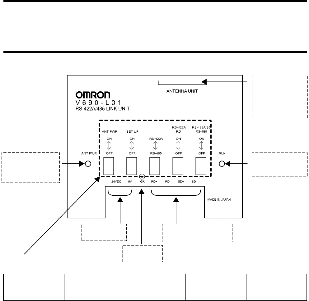
4-3 Link Unit
4-21
(A) (B) (C) (D) (E)
ANT PWR SET UP RS-422A/RS-485 RS-422A RD
(Receiving)
RS-422A SD (Sending)
RS-485
Connect a connector
(D-SUB 15-pin) of the
RS-422A/RS-485 link
unit connecting cable.
(Model V690-A5!)
Indicator "RUN"
Turns on when the 24
VDC power supply
turns on.
Indicator "ANT PWR"
Turns on when 24 VDC
is supplied to the
antenna.
Connect 24 VDC
power supply.
Ground accord-
ing to Class D.
Connect a communication
line of RS-422A/RS-485.
Switch Function
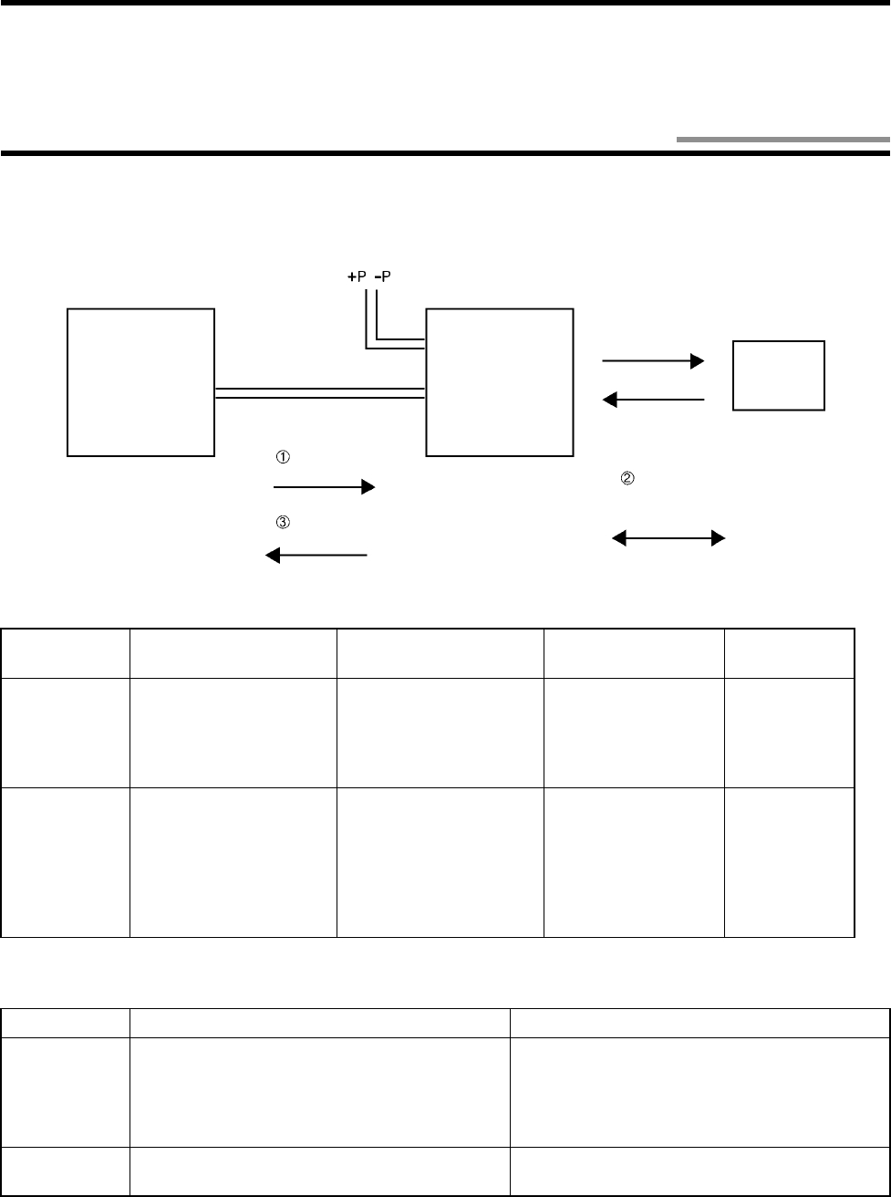
5-1
The V690 Series REID system communicates with a tag according to the instruction of a command (1) sent from a host device and
returns the result to the host device as the response (3).
♦
♦♦
♦Operation mode and setting mode of antenna
Two modes are available in the operation of antenna. Available commands vary depending on the mode. Refer to Section 5-4.
♦
♦♦
♦Tag status after a command has been executed
Two modes are available after a command has been executed.
Mode How to change mode Description
Host communication
condition Antenna
station number
Operation
mode
Disconnect the two antenna
terminals "+P" and "-P" and
reset the power supply (turn
off the power supply once
and turn on it again).
Use for a normal opera-
tion.
Setting can be
changed.
(Refer to Section 5-9-
7.)
00 to 31 (Initial
value 00)
Setting mode
Short-circuit the two
antenna terminals "+P"
and "-P" and reset the
power supply.
• A simplified communication func-
tion (without connection to a host
device) is available. Refer to Sec-
tion 3-4.
• A tag communication command
and radio wave transmission ON/
OFF command cannot be used.
Fixed.
(Refer to Section 5-9-
7.)
Use when the host
communication condi-
tion is unknown.
99
Mode How to change mode Description
Sleep state Specify S! or R! in communication designation
with a command. • Tag battery power can be saved.
• A tag cannot be started in 0.2 seconds immedi-
ately after sleep.
• Use for FIFO (First-In First-Out). Refer to (3) of
Section 5-2-1.
Standby state Specify W! or C! in communication designation
with a command. • Use when several commands are executed con-
secutively to one tag.
Host Device Communication line
Command
Response
Communication between
the antenna and tag
Read/Write antenna ID Tag
Chapter 5 Control from Host Device
5-1 Operation Status of Read/Write Antenna and ID Tag
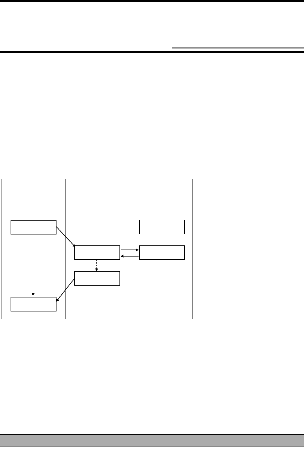
5-2
Operation sequence, such as communication to a tag and response return timing, varies depending on the designation with a command.
You need to use properly according to the tag status in an antenna communication area and a type of communication with a host device.
5-2-1 Communication Mode with Command
(1) Trigger
Communication is performed to a tag in an antenna communication area when a command has been received. Therefore, check that the
tag is in the antenna communication area and then execute a command. If there is no tag in the antenna communication area when a
command has been executed, the antenna returns an error response.
When a command is executed, the tag is in a sleep mode or standby mode.
• Sleep mode (Communication designation SU or SN)
The tag battery power can be saved in the sleep mode. The tag cannot be started in 0.2 seconds immediately after sleep.
• Standby mode (Communication designation WU or WN)
To execute several commands consecutively to one tag, enable the standby mode.
Correct Usage
Trigger, check that a tag is in the antenna communication area.
(Host device) (Antenna) (Tag)
Not yet
approached
Tag
Trigger command
Command pro-
cess ended
Communication
process
Response
Tag
Sleep or
standby
(1)The host device must check that the tag is
in the antenna communication area and
then execute a command.
(2)The antenna communicates to the tag
according to the command.
(3)When the process has completed, the
antenna returns a response of the process
end to the host device and becomes ready
to accept a command.
5-2 Communication Operation Sequence
5-2 Communication Operation Sequence
5-3
(2) Single Auto
An antenna waits until a tag approaches the communication area and then communicates with the tag.
To terminate Single Auto:
• When an auto repeat cancel command (C2) is issued, the antenna discontinues Single Auto and becomes ready to accept a command.
• When any other command is issued, the antenna discontinues Single Auto and executes the new command. If the command format
is wrong, the antenna returns the format error response 14 and discontinues Single Auto.
• If a waiting time for tag (refer to Section 5-9-4) is set, when the waiting time for tag has been passed, the antenna returns the no-tag
error response 72 and discontinues Single Auto.
When a command is executed, the tag is in a sleep mode or standby mode.
• Sleep mode (Communication designation SU or SN)
The tag battery power can be saved in the sleep mode. The tag cannot be started in 0.2 seconds immediately after sleep.
• Standby mode (Communication designation WU or WN)
To execute several commands consecutively to one tag, enable the standby mode.
(Host device) (Antenna) (Tag)
Not yet
approached
Single Auto
command
Command pro-
cess ended
Communication
process
Response
Tag
Sleep or
standby
(1)The Single Auto command is sent from
the host device.
(2)The antenna does not return a response
until the tag approaches. So, the host
device waits for a response.
(3)When the tag passes the front of the
antenna, the antenna communicates with
the tag according to a command.
(4)When the process has completed, the con-
troller returns a response of the process
end to the host device and becomes ready
to accept a command.
Not yet
approached
Waits for tag
approaching
Waits for tag
approaching
Pass
5-2 Communication Operation Sequence
5-4
(3) Repeat
When an antenna receives a command from a host device, the antenna waits for tag approaching, communicates with the tag whenever
the tag passes the antenna communication area, and returns a response to the host device.
After the command is executed, by specifying the sleep state (S!) as the communication designation, FIFO (First-In First-Out. Refer to
Section 3-1) is enabled.
To terminate repeat state:
• When an auto repeat cancel command (C2) is issued, the antenna discontinues Repeat and becomes ready to accept a command.
• When any other command is issued, the antenna discontinues Repeat and executes the new command. If the command format is
wrong, the antenna returns the format error response 14 and discontinues Repeat.
If a waiting time for tag (refer to Section 5-9-4) is set, when the waiting time for tag has been passed, the antenna returns the no-tag error
response 72 and continues Repeat.
Repeat command
(Host device) (Antenna) (Tag)
Receives a
response
Communication
process
Response
Tag (1)
(Waits for a response)
(Waits for tag approaching)
(Waits for tag approaching)
Not yet approached
Not yet approached
Receives a
response
Communication
process
Response
Tag (2)
(Waits for a response)
(Waits for tag approaching)
Pass
Pass
Sleep
(Waits for tag approaching)
Pass
(Waits for a response)
Waits for tag
approaching
Not yet approached
Not yet approached
(1)The Repeat command is sent from the host device.
(2)The antenna does not return a response until the tag
approaches.
(3)When the tag passes the front of the antenna, the
antenna communicates with the tag according to a com-
mand.
(4)When the process has completed, the antenna returns a
response of the communication end to the host device
and waits for the next tag approaching.
(5)When the tag passes the front of the antenna again, the
antenna communicates with the tag.
(6)When the process has completed, the antenna returns a
response of the communication end to the host device.
Sleep

5-2 Communication Operation Sequence
5-5
5-2-2 Communication Mode with Communication Designation
(1) Polling
When one host device controls several antennas, if a normal auto command is used, a response is returned when the tag communication
has completed. In this case, several antennas return a response. For polling, the antenna returns the response at the request of the host
device. So, some responses are not returned simultaneously and several antennas can be controlled.
To terminate polling:
• When an auto repeat cancel command (C2) is issued, the antenna discontinues Polling Auto/Polling Repeat and becomes ready to
accept a command.
• When any other command is issued, the antenna discontinues a polling mode and executes the new command. If the command for-
mat is wrong, the antenna returns the format error response 14 and discontinues Polling Auto/Polling Repeat.
• If a waiting time for tag (refer to Section 5-9-4) is set, when the waiting time for tag has been passed, the antenna returns the no-tag
error response 72 and discontinues Polling Auto. For Polling Auto, the antenna returns an error response and continues Polling
Repeat.
When a command is executed, the tag is in a sleep mode or standby mode according to the communication designation (C!, R!).

5-2 Communication Operation Sequence
5-6
(Host device) (Antenna)
<Station No. 00> (Tag)
(Waits for tag approaching)
Not yet
approached
(Tag)
Polling Auto command
Station No. 00
Receives a response
Polling response
Polling Auto command
Station No. 01
Not yet
approached
(Waits for tag approaching)
Not yet
approached
Not yet
approached
Receives a response
Receives a response
Requests a response
Station No. 00
Response of "Not yet
approached"
Requests a response
Station No. 01
Receives a response
Communication process
Response
Tag
Requests a response
Station No. 00
Receives a response
Requests a response
Station No. 01
Receives a response
(Antenna)
<Station No. 01>
Polling response
Response of "Not yet
approached"
(Waits for tag approaching)
Pass
Not yet
approached
(Waits for tag approaching)
Response of "Not yet
approached"
(Waits for tag approaching)
(1)The Polling Auto command is sent from
the host device to the antenna station
No. 00.
(2)Immediately after receiving the com-
mand, the antenna returns a response
that the command has been accepted.
(3)The Polling Auto command is sent from
the host device to the antenna station
No. 01.
(4)Immediately after receiving the com-
mand, the antenna returns a response
that the command has been accepted.
(5)The host device can inquire the progress
of process using a response request. If
the tag has not yet approached, a
response of "Not yet approached" is
returned to the response request.
(6)When the tag passes the front of the
antenna station No. 00, the antenna sta-
tion No. 00 communicates with the tag.
(7)When the response request is sent to the
antenna which ended the communica-
tion with the tag, the antenna returns a
response of process result and becomes
ready to accept a command.
5-2 Communication Operation Sequence
5-7
(2) Multi
The communication to all the tags in the antenna communication area can be made. Multi Trigger and Multi Repeat commands are
available:
In Multi Trigger, the antenna communicates with all the tags in the communication area when it receives a command. When the process
has completed, the antenna returns the communication end response (termination code 72).
In Multi Repeat, the antenna waits for a tag when it receives a command. The antenna continues to communicate with all the tags com-
ing in the communication area.
To terminate Multi Repeat:
• When an auto repeat cancel command (C2) is issued, the antenna discontinues Multi Repeat and becomes ready to accept a com-
mand.
• When any other command is issued, the antenna discontinues Multi Repeat and executes the new command. If the command format
is wrong, the antenna returns the format error response 14 and discontinues Multi Repeat.
If a waiting time for tag (refer to Section 5-9-4) is set, when the waiting time for tag has been passed, the antenna returns the no-tag error
response 72 and continues Multi Repeat.
When a command is executed, the tag is in a sleep mode according to the communication designation (S!).
An example of Multi Trigger is shown below.
Multi S/M/L
Time Slot method (refer to "Appendix 1 - Glossary") is used to detect several tags. Select S, M or L to optimize the Multi communica-
tion time.
Code Number of communicated tags Number of time slots
S
M
L
Approximately 4 tags
Approximately 8 tags
Approximately 16 tags
8
16
32
Multi Trigger command
(Host device) (Antenna) (Tag)
Receives a response
Communication process
Response
Communication process
Response
"Communication End" response "72"
Receives a response
Receives a response
Tag (0)
Tag (1)
5-2 Communication Operation Sequence
5-8
5-2-3 Other Communication Mode
(1) Selective Access
Every tag has an inherent ID code which cannot be rewritten. By using this ID code, communication can be performed to a particular
tag of those in an antenna communication area.
(2) Radio Wave Transmission ON mode
Usually, an antenna transmits a radio wave after receiving a command from a host device. When the Radio Wave Transmission ON
mode of antenna is enabled, regardless of any command from a host device, the antenna transmits a radio wave always. In the Radio
Wave Transmission ON mode, an application that the ID tag moves fast may be available.
Mode Initial value How to change mode Radio wave transmission status
Radio Wave
Transmission
OFF mode
The antenna does not transmits a radio wave when
it waits for a command. When the antenna accepts
a communication command, the antenna transmits
a radio wave and communicate with a tag. When
the communication has ended, the antenna stops
transmitting a radio wave.
Radio Wave
Transmission
ON mode
Radio Wave Transmission ON (A1) Refer to
Section 5-9-1.
How to switch to the Radio Wave Transmis-
sion OFF mode
• Radio Wave Transmission OFF command
(A0) Refer to Section 5-9-1.
• Reset command (C0) Refer to Section 5-9-2.
• Reset the power supply.
Regardless of any command from a host
device, the antenna transmits a radio
wave always.
Executes ID Code Read (I!)
Refer to Section 5-7-2. Reads an ID code of a tag in the communication area.
Executes Tag Designation Read command
Refer to Sections, 5-7-3, 5-7-5 and 5-7-7.
Uses an ID code and executes a command to a designated tag.
Executes Radio Wave Transmission ON (A1)
Refer to Section 5-9-1.
Executes Read/Write
5-9
(1) Command
A text section of command consists of a command and option section which specifies information. The antenna receives a range from
STX receiving to ETX correctly and, only when the antenna station No. and DA match, executes a command. After receiving STX,
when the antenna receives STX again by the time the antenna receives ETX, the second STX shall be the beginning of the command.
You can specify whether BCC is enabled or disabled. By default, BCC is disabled. How to specify whether BCC is enabled or disabled,
refer to Section 5-9-7.
Note: "h" is a hexadecimal notation.
(2) Response
A text section of response consists of a command, termination code and data section.
Name Description
STX Shows the beginning of a command response frame. It corresponds to 02h (hexadecimal number)
in the ASCII code table.
DA Destination (antenna) station number. Operation mode "00" to "31" (initial value is "00"). Setting
mode "99". A station number in the operation mode can be changed in "Station Number Setting".
SA Source (host device) station number "80" to "89". Several host device can be used. If only one
host device is used, specify "80".
Command Code Specifies a command for antenna operation. For available command codes, refer to the command
list in Section 5-4.
Option Specifies the communication of command execution, reading data and writing data. For details,
refer to the formats of commands after Section 5-7.
ETX Shows the end of command response. It corresponds to 03h (hexadecimal number) in the ASCII
code.
BCC Block Check Character (referred to as "BCC"). Calculation result of horizontal parity immediately
after STX to ETX. It is displayed in one character. For example of calculation of BCC, refer to the
next page.
• Disabling BCC *A value below shows the number of characters.
• Enabling BCC
Command code
Option
Command code
Option
• Disabling BCC *A value below shows the number of characters.
• Enabling BCC
Command code
Command code
Termination code
Data
Termination code
Data
5-3 Communication Response Format
5-3 Communication Response Format
5-10
♦
♦♦
♦Example of calculation of BCC
Use to detect data error due to noise in data communication between a host device and antenna. BCC is one-character data that XOR of
every data was executed per character in a range from DA to ETX. For details, refer to "JIS5001 Character Configuration on Transmis-
sion Line and Horizontal Parity Usage".
An example of calculation is described below.
Example: ID Code Read, Single Trigger
Note: "h" is a hexadecimal notation.
DA 0 0011 0000
XOR
00011 0000
XOR
SA 8 0011 1000
XOR
00011 0000
XOR
Command Code I 0100 1001
XOR
3 0011 0011
XOR
Communication Designation W
0101 0111
XOR
U 0101 0101
XOR
ETX 03H 0000 0011
0111 0011
7h 3h
Name Description
DA Destination (host device) station number "80" to "89".
SA Source (antenna) station number. Operation mode "00" to "31" (initial value is "00"). Setting mode
"99".
Command Code Returns a command code of sent command.
Termination Code Responds the result of command execution as a termination code. For the termination code, refer
to the termination code list in Section 5-10.
Data Responds a response number, ID code, read data, etc. For details, refer to the formats of com-
mands after Section 5-7.
Data
Name STX DA SA
Command
Code
Communication Desig-
nation ETX BCC
Data 02h “00” “80” “I3” “W” “U” 03h 73h
5-11
There are three types of commands as follows:
(1) Tag communication command: A command to communicate with a tag
(2) Antenna operation command: A command to operate an antenna when communicating with a tag.
(3) Antenna setting command: A command to set an antenna before operating a system.
(1) Tag communication command
Use this command when an antenna is in an operation mode. This command cannot be used in a setting mode. Refer to Section 5-1.
Command
Communication designation
* Direct response: A communication mode that a command is received from a host device and a response is made immediately after
the command execution.
Command
Communication Mode
(Sections 5-2-1)
Command Code Function
Read
(Sections 5-7-1 and
5-7-3)
Trigger R3 Reads data, Write Protect setting, date of produc-
tion and waiting time for sleep.
Single Auto R6
Repeat R9
ID Code Read
(Section 5-7-2)
Trigger I3 Reads an ID code of tag.
* The ID code is a value inherent to tag and cannot
be rewritten.
Single Auto I6
Repeat I9
Write Without Verifi-
cation
(Sections 5-7-4 and
5-7-5)
Trigger W3 Writes data, Write Protect setting and waiting time
for sleep.
Single Auto W6
Repeat W9
Write With Verifica-
tion
(Sections 5-7-4 and
5-7-5)
Trigger W1 Writes data, Write Protect setting and waiting time
for sleep. Reads and checks written data after writ-
ing.
Single Auto W4
Repeat W7
Data Fill
(Sections 5-7-6 and
5-7-7)
Trigger F3 Writes a fixed data into a specified area in memory.
For example, by writing "0" into all areas in memory,
everything is cleared.
Single Auto F6
Repeat F9
Communication Test
(Section 5-7-8) Trigger T0 Communication test between an antenna and tag.
Direct response / Polling
((1) in Section 5-2-2)
One tag / Multi (several
tags) / Tag designation
((2) in Section 5-2-2 and
(1) in Section 5-2-3)
Tag status after com-
mand execution
(Section 5-1)
Communication designation
(1) (2)
Direct response One tag Sleep S U
Direct response One tag Standby W U
Polling One tag Standby C U
Direct response Multi (several tags) Sleep S S/M/L
Polling Multi (several tags) Sleep R S/M/L
Direct response Tag designation Sleep S N
Direct response Tag designation Standby W N
Communication designation (1) W: Direct response. A tag after execution is in a standby state.
S: Direct response. A tag after execution is in a sleep state.
C: Polling. A tag after execution is in a standby state.
R: Polling. A tag after execution is in a sleep state.
Communication designation (2) U: One tag access without ID code designation.
N: One tag access with ID code designation.
S/M/L: Several tag access.
5-4 Communication and Communication Designation List
5-4 Communication and Communication Designation List
5-12
Several tag access S/M/L
The time slot method is used to detect several tags. Select S/M/L to minimize the communication time of Multi. (Even if the number
specified in S/M/L and the number of actual tags do not match, the Multi communication can be made. However, it may take a long
time to communicate.)
(2) Antenna operation command
Any command to operate an antenna is executed immediately.
Symbol Number of estimated tags in
communication area at a time Number of time slots
S
M
L
Approximately 4 tags.
Approximately 8 tags.
Approximately 16 tags.
8
16
32
Command Name
(Referred item) Command
Code Operation
Mode Setting
Mode Function
Auto Repeat Cancel
(Section 5-8-1) C2
Enabled
Cancels and disables Auto and Repeat commands.
Reset (Section 5-8-2) C0 Enabled
• Clears data read from a tag at polling. A response
is not returned by the Request to Response (H0)
command.
• Clears the immediately preceding response. A
response is not returned by the Request To
Retransmit (H1) command.
• Changes the Radio Wave Transmission ON mode
into the OFF mode.
• Enables the host communication condition setting
and station number setting commands.
Request to Respond
(Section 5-8-3) H0 Requests a response from a tag during polling.
Request to Retrans-
mit (Section 5-8-4) H1 Enabled Requests to retransmit the immediately preceding
response.
5-4 Communication and Communication Designation List
5-13
(3) Antenna setting command
Any command to set an antenna is executed immediately.
Note 1. To enable "Host Communication Condition Setting" and "Station Number Setting", you must issue a reset command (Section
5-8-2) or reset the power supply after issuing a command.
Note 2. 9.6 kbps, data length 7 bits, even parity, stop bit 2, no BCC. (Refer to Section 5-9-7)
Command name
(Referred item)
Operation
mode
Setting
mode
After resetting power
supply or executing reset
Function Initial
value
Radio Wave Transmis-
sion OFF (Section 5-9-1) A0
Enabled
Disabled
No change in the radio
wave OFF mode.
Selects the radio wave transmis-
sion OFF mode. OFF
mode
Radio Wave Transmission
ON (Section 5-9-1)
A1
Returns to the radio
wave OFF mode.
Selects the radio wave ON mode.
Communication Range
Selection (Section 5-9-2) A4
Enabled
Setting before
resetting does
not change.
Selects the range selection mode
(2 m/5 m). 2 m
mode
Radio Wave Channel
Selection (Section 5-9-2) A5 Selects a radio wave channel (0 -
9). 5
(2450 MHz)
Radio Wave Output Sta-
tus Read (Section 5-9-3) A6 Reads a communication range
mode and radio wave channel.
Setting of Time to Wait
Tag (Section 5-9-4)
T4
Sets a waiting time for communication with
a tag after command execution when exe-
cuting Auto or Repeat command.
Unlimited
Command Data
Response Time Setting
(Section 5-9-5)
H4 Sets a command response time,
data response time intervals. 10 ms
10 ms
Read Data Length Set-
ting
(Section 5-9-6)
H3
Sets maximum data length which
can be returned by one response of
data read command.
256 bytes
Host Communication
Condition Setting
(Section 5-9-7)
H5
Enabled (Note 1)
Sets conditions of communication
with a host device. 27E200
(Note 2)
Station Number Setting
(Section 5-9-8) H6 Sets an antenna station number. 00
Setting Read
(Section 5-9-9) M2 Disabled Reads an antenna setting value.
5-14
You can specify a type of code used to transmit data to be read or written between a host device and Read/Write antenna.
ASCII code designation and hexadecimal code designation are available.
♦
♦♦
♦ASCII code (JIS 8 unit code) designation "A"
1 byte of data of tag is transmitted directly as ASCII code or JIS 8 unit code. Transmitted one character is equal to a 1 byte of data in
a tag. Character data can be read/written directly.
Do not use any control code, such as [SOH] and [CR], in transmission data. Otherwise, a command error occurs.
<Example 1 of writing>
When "OMRON" is specified in 5 bytes of memory beginning with 10h (hexadecimal number) as writing data, data is written into tag
memory as shown below.
Command
Response
<Example 1 of reading>
In this data shown here, when 5 bytes of memory beginning with 10h (hexadecimal number) is read out, the read data is "OMRON".
Command
Response
<Example 2 of writing>
When "1234" is specified in 4 bytes of memory beginning with 10h (hexadecimal number) as writing data, data is written into tag mem-
ory as shown below.
Command
Response
STX DA SA Command code
Communication designation
Split flag Code designation Start address Number of written bytes Written data ETX
00 80 W1 SU A A 0010 0005 OMRON
STX DA SA Command code Termination code Response number ID code ETX
80 00 W1 00 01 ∗∗∗∗∗∗∗∗
STX DA SA Command code
Communication designation
Split flag Code designation Start address Number of read bytes ETX
00 80 R3 SU A A 0010 0005
STX DA SA Command code
Termination code Response number
ID code Split flag
Code designation
Start address
Number of read bytes
Number of read data
ETX
80 00 R3 00 01 ******** A A 0010 0005 OMRON
STX DA SA Command code
Communication designation
Split flag Code designation Start address Number of written bytes Written data ETX
00 80 W1 SU A A 0010 0004 1234
STX DA SA Command code Termination code Response number ID code ETX
80 00 W1 00 01 ∗∗∗∗∗∗∗∗
5-5 Data Code Designation
ASCII code designation
ASCII code designation
Tag Memory
Address Tag Memory
Address
Tag Memory
Address
5-5 Data Code Designation
5-15
<Example 2 of reading>
In this data shown at the previous page, when 4 bytes of memory beginning with 10h (hexadecimal number) is read out, the read data is
"1234".
Command
Response
♦
♦♦
♦Hexadecimal code designation "H"
1 byte of data of tag is converted into two hexadecimal numbers ("00" to "FF") and those numbers are transmitted. Transmitted two
characters are equal to 1 byte of data in a tag. Be sure to specify written data in two hexadecimal numbers from "00" to "FF" (even).
If any odd number data is specified, a command error occurs.
<Example of writing>
When "1234" is specified in 2 bytes of memory beginning with 20h (hexadecimal number) as writing data, data is written into tag mem-
ory as shown below.
Command
Response
<Example of reading>
In this data shown here, when 2 bytes of memory beginning with 20h (hexadecimal number) is read out, the read data is "1234".
Command
Response
STX DA SA Command code
Communication designation
Split flag Code designation Start address Number of read bytes ETX
00 80 R3 SU A A 0010 0004
STX DA SA Command code
Termination code Response number
ID code Split flag
Code designation
Start address
Number of read bytes
Read data ETX
80 00 R3 00 01 ******** A A 0010 0004 1234
STX DA SA Command code
Communication designation
Split flag Code designation Start address Number of written bytes Written data ETX
00 80 W1 SU A H 0020 0002 1234
STX DA SA Command code Termination code Response number ID code ETX
80 00 W1 00 01 ∗∗∗∗∗∗∗∗
STX DA SA Command code
Communication designation
Split flag Code designation Start address Number of read bytes ETX
00 80 R3 SU A H 0020 0002
STX DA SA Command code
Termination code Response number
ID code Split flag
Code designation
Start address
Number of read bytes
Number of read data
ETX
80 00 R3 00 01 ******** A H 0020 0002 1234
Hexadecimal code designation
Tag Memory
Address
5-16
Depending on a type of command and the communication designation, the command transmission from a host device to an antenna and
the response from the antenna to the host device vary.
(1) No response
When the host device issues a reset command to the antenna, the antenna does not send any response, performs resetting and waits for a
command.
(2) One to one
When the host device issues Single Trigger and Single Auto of a tag communication command, or when the host device issued an
antenna operation command and antenna setting command, the antenna returns one response per command.
(3) Several responses
When the host device issues Single Repeat, Multi Trigger and Multi Repeat, the antenna returns several responses per command.
Host Device
Antenna
Reset Command
Execution of Resetting
Host Device
Antenna
Command
Response
Host Device
Antenna
Command
Response Response Response Response
5-6 Communication Response Flow
5-17
5-7-1 Read
Reads data from a tag.
<Command Format> * A figure below shows the number of characters.
Command code and communication designation
Start address, number of read bytes
DA Destination (antenna) station number. "00" to "31". This can be
modified in "5-9-8 Station Number Setting". Initial value "00"
SA
Source (host device) station number. "80" to "89". If only one host device is used, specify "80".
Command code Specify according to the table below.
Communication designation
Split flag Specify "A".
Code designation Specify whether data read out of a tag is ASCII code or hexadecimal code.
A: ASCII code
H: Hexadecimal code
Start address Specify according to the table below.
Number of read bytes
Command Tag status after
execution
Command
code
Communica-
tion designation
Remarks
Single Trigger Sleep
R3
SU
Single Trigger Standby WU
Any other command can be executed to the tag immediately after it.
Multi Trigger (approximately 4 tags)
Sleep
SS
Multi Trigger (approximately 8 tags) SM
Multi Trigger (approximately 16 tags) SL
Single Auto Sleep
R6
SU
Single Auto Standby WU
Any other command can be executed to the tag immediately after it.
Polling Single Auto CU
Single Repeat
Sleep R9
SU FIFO
Multi Repeat (approximately 4 tags) SS
Multi Repeat (approximately 8 tags) SM
Multi Repeat (approximately 16 tags) SL
Polling Single Repeat RU For a query command of polling, refer
to "5-8-3 Request To Respond".
Polling Multi Repeat (approximately 4 tags)
RS
Polling Multi Repeat (approximately 8 tags)
RM
Polling Multi Repeat (approximately 16 tags)
RL
Read content Start address Number of read bytes
ASCII code Hexadecimal code
Data Reading start address
("0000" to "1FFF")
* Hexadecimal number
Specify the number of read bytes
("0001" to "2000")
* Hexadecimal number
Specify the number of read bytes
("0001" to "2000")
* Hexadecimal number
Write Protect setting "WPRO" Unavailable "0004" * Refer to Section 3-6.
Date of production "DATE" "0008" * Refer to Section 2-2-3.
Waiting time for sleep "SLEP" "0004" * Refer to Section 3-7.
Split flag
Command
code Communi-
cation des-
ignation
Code designation
Start address Number of
read bytes
(BCC)
* It can be specified whether BCC is enabled or disabled.
5-7 Tag Communication Command
5-7 Tag Communication Command
5-18
<Response Format> * A figure below shows the number of characters.
<Polling Response Format> * A figure below shows the number of characters.
Response immediately after a polling command is issued.
DA Destination (host device) station number. * In the command format, the destination is an
antenna.
SA Source (antenna) station number.
Termination code "00": For a normal end. For any other termination codes, refer to "5-10 Termination Code
List".
Response number Consecutive number of response of tag. For one response, only "01". For several
responses, "02" or more.
ID code ID code of tag. This is inherent to tag and cannot be rewritten.
Split flag
"Data read length" can be set in an antenna (Refer to Section 5-9-6). An initial value is 256
bytes.
• If number of read bytes ≤ data read length, the flag is "A".
• If number of read bytes > data read length, the flag is divided and sent to a host and sev-
eral responses are made.
"T" for data start. "C" for data continuation. "E" for final data.
Read data Data read out of a tag. Number of characters of data is as follows:
ASCII code is specified: Number of read bytes.
Hexadecimal code is specified: Number of read bytes x 2.
Termination code Fixed to "00".
Correct Usage
For an available range of number of read bytes, check the ID tag memory capacity.
Split flag
Command
code
Code designation
Start address Number of
read bytes
(BCC)
* It can be specified whether BCC
is enabled or disabled.
Termination
code Response
number
ID code
Specified number
Read data
Command
code Termination
code
(BCC)
* It can be specified whether BCC is enabled or disabled.
5-7 Tag Communication Command
5-19
5-7-2 ID Code Read
Reads an ID code from a tag. The ID code is inherent to a tag and cannot be rewritten.
<Command Format> * A figure below shows the number of characters.
Command code and communication designation
<Response Format> * A figure below shows the number of characters.
DA Destination (antenna) station number. "00" to "31". This can
be modified in "5-9-8 Station Number Setting". Initial value "00"
SA
Source (host device) station number. "80" to "89". If only one host device is used, specify "80".
Command code Specify according to the table below.
Communication designation
Command Tag status after
execution
Com-
mand
code
Communi-
cation des-
ignation Remarks
Single Trigger Sleep
I3
SU
Single Trigger Standby WU Any other command can be executed
to the tag immediately after it.
Multi Trigger (approximately 4 tags)
Sleep
SS
Multi Trigger (approximately 8 tags) SM
Multi Trigger (approximately 16 tags) SL
Single Auto Sleep
I6
SU
Single Auto Standby WU Any other command can be executed
to the tag immediately after it.
Polling Single Auto CU
Single Repeat
Sleep I9
SU FIFO
Multi Repeat (approximately 4 tags) SS
Multi Repeat (approximately 8 tags) SM
Multi Repeat (approximately 16 tags) SL
Polling Single Repeat RU For a query command of polling, refer
to "5-8-3 Request to Respond".
Polling Multi Repeat (approximately 4 tags)
RS
Polling Multi Repeat (approximately 8 tags)
RM
Polling Multi Repeat (approximately 16 tags)
RL
DA
Destination (host device) station number. * In the command format, the destination is an antenna.
SA Source (antenna) station number.
Termination code
"00": For a normal end. For any other termination codes, refer to "5-10 Termination Code List".
Response number Consecutive number of response of tag. For one response, only "01". For several
responses, "02" or more.
ID code ID code of tag. This is inherent to tag and cannot be rewritten.
Command
code Communica-
tion designa-
tion
(BCC)
* It can be specified whether BCC is enabled or disabled.
Command
code Termination
code Response
number
ID code
(BCC)
* It can be specified whether BCC is enabled or disabled.
5-7 Tag Communication Command
5-20
<Polling Response Format> * A figure below shows the number of characters.
Response immediately after a polling command is issued.
Termination code Fixed to "00".
Command
code Termination
code
(BCC)
* It can be specified whether BCC is enabled or disabled.
5-7 Tag Communication Command
5-21
5-7-3 Tag Designation Read
Reads data from a particular ID tag.
<Command Format> * A figure below shows the number of characters.
Start address, number of read bytes
DA Destination (antenna) station number. "00" to "31". This can
be modified in "5-9-8 Station Number Setting". Initial value "00"
SA
Source (host device) station number. "80" to "89". If only one host device is used, specify "80".
Command code R3: Single Trigger
Communication
designation
Gives communication designation to a tag.
SN: A tag will be in a sleep state after execution.
WN: A tag will be in a standby state after execution.
ID code Specify an ID code of a particular tag.
Split flag Specify "A".
Code designation Specify whether data read out of a tag is ASCII code or hexadecimal code.
A: ASCII code
H: Hexadecimal code
Start address Specify according to the table below.
Number of read bytes
Read content Start address Number of read bytes
ASCII code Hexadecimal code
Data
Reading start address
("0000" to "1FFF")
* Hexadecimal number
Specify the number of read bytes
("0001" to "2000")
* Hexadecimal number
Specify the number of read bytes
("0001" to "2000")
* Hexadecimal number
Write Protect setting "WPRO" Unavailable "0004" * Refer to Section 3-6.
Date of production "DATE" "0008" * Refer to Section 2-2-3.
Waiting time for sleep
"SLEP" "0004" * Refer to Section 3-7.
Split flag
Command
code Communi-
cation des-
ignation
Code designation
Start address Number of
read bytes
(BCC)
* It can be specified whether BCC is
enabled or disabled.
ID code
5-7 Tag Communication Command
5-22
<Response Format> * A figure below shows the number of characters.
DA Destination (host device) station number. * In the command format, the destination is an
antenna.
SA Source (antenna) station number.
Termination code "00": For a normal end. For any other termination codes, refer to "5-10 Termination Code
List".
Response number Fixed to "01".
Split flag
"Data read length" can be set in an antenna (Refer to Section 5-9-6). An initial value is 256
bytes.
If number of read bytes ≤ data read length, the flag is "A".
If number of read bytes > data read length, the flag is divided and sent to a host and several
responses are made.
"T" for data start. "C" for data continuation. "E" for final data.
Read data Data read out of a tag. Number of characters of data is as follows:
ASCII code is specified: Number of read bytes.
Hexadecimal code is specified: Number of read bytes x 2.
Correct Usage
• Before executing this command, you need to use an ID code read command (I!) to check the ID code of the tag.
• For an available range of number of read bytes, check the ID tag memory capacity.
Split flag
Command
code
Code designation
Start address Number of
read bytes
(BCC)
* It can be specified whether BCC
is enabled or disabled.
Termination
code Response
number
ID code Read data
Specified number
5-7 Tag Communication Command
5-23
5-7-4 Write
Writes data into a tag.
<Command Format> * A figure below shows the number of characters.
Command code and communication designation
DA Destination (antenna) station number. "00" to "31". This can
be modified in "5-9-8 Station Number Setting". Initial value "00"
SA
Source (host device) station number. "80" to "89". If only one host device is used, specify "80".
Command code Specify according to the table below.
Communication designation
Split flag Specify "A".
Code designation Specify whether a data read out of a tag is ASCII code or hexadecimal code.
A: ASCII code
H: Hexadecimal code
Start address Specify according to the table below.
Number of written bytes
Command Tag status after
execution
Command
code
Communication
designation
Remarks
Single Trigger Sleep
W1
W3
SU
Single Trigger Standby WU
Any other command can be executed to the tag immediately after it.
Multi Trigger (approximately 4 tags)
Sleep
SS
Multi Trigger (approximately 8 tags) SM
Multi Trigger (approximately 16 tags) SL
Single Auto Sleep W4
W6
SU
Single Auto Standby WU
Any other command can be executed to the tag immediately after it.
Polling Single Auto CU
Single Repeat
Sleep W7
W9
SU FIFO
Multi Repeat (approximately 4 tags) SS
Multi Repeat (approximately 8 tags) SM
Multi Repeat (approximately 16 tags) SL
Polling Single Repeat RU For a query command of polling, refer
to "5-8-3 Request to Respond".
Polling Multi Repeat (approximately 4 tags)
RS
Polling Multi Repeat (approximately 8 tags)
RM
Polling Multi Repeat (approximately 16 tags)
RL
With verification read W1, W4, W7
After an antenna writes data into a tag, the antenna reads the data from the tag
and check whether the data is correct. If the data is not correct, the termination
code becomes 71. Writing is reliable, but the communication time with verification
read is twice the length of that without verification read.
Without verification read W3, W6, W9 After an antenna writes data into a tag, the antenna does not read the
data.
Split flag
Command
code Communi-
cation des-
ignation
Code designation
Start address Number of
written bytes
(BCC)
* It can be specified whether BCC is
enabled or disabled.
Written data
Specified number
5-7 Tag Communication Command
5-24
Start address, number of read bytes
<Response Format> * A figure below shows the number of characters.
<Polling Response Format> * A figure below shows the number of characters.
Response immediately after a polling command is issued.
Written content Start address Number of written bytes
ASCII code Hexadecimal code
Data
Reading start
address
("0000" to "1FFF")
* Hexadecimal number
Specify the number of written
bytes
("0001" to "2000")
* Hexadecimal number
Specify the number of written
bytes
("0001" to "1000")
* Hexadecimal number
Write Protect setting "WPRO" Unavailable "0004" * Refer to Section 3-6.
Waiting time for sleep
"SLEP" "0004" * Refer to Section 3-7.
DA Destination (host device) station number. * In the command format, the destination is an
antenna.
SA Source (antenna) station number.
Termination code "00": For a normal end.
For any other termination codes, refer to "5-10 Termination Code List".
Response number Consecutive number of response of tag. For one response, only "01". For several
responses, "02" or more.
ID code ID code of tag. This is inherent to tag and cannot be rewritten.
Termination code Fixed to "00".
Correct Usage
For an available range of number of written bytes, check the ID tag memory capacity.
Command
code Termination
code Response
number
ID code
(BCC)
* It can be specified whether BCC is enabled or disabled.
Command
code Termination
code
(BCC)
* It can be specified whether BCC is enabled or disabled.
5-7 Tag Communication Command
5-25
5-7-5 Tag Designation Write
Writes a data into a particular ID tag.
<Command Format> * A figure below shows the number of characters.
Start address, number of read bytes
DA Destination (antenna) station number. "00" to "31". This can
be modified in "5-9-8 Station Number Setting". Initial value "00"
SA
Source (host device) station number. "80" to "89". If only one host device is used, specify "80".
Command code W1: Single Trigger, with verification read. * For the verification, refer to Section 5-7-4.
W3: Single Trigger, without verification read.
Communication designa-
tion
Gives communication designation to a tag.
SN: A tag will be in a sleep state after execution.
WN: A tag will be in a standby state after execution.
ID code Specify an ID code of a particular tag.
Split flag Specify "A".
Code designation Specify whether data read out of a tag is ASCII code or hexadecimal code.
A: ASCII code
H: Hexadecimal code
Start address Specify according to the table below.
Number of written bytes
Written content Start address Number of written bytes
ASCII code Hexadecimal code
Data
Reading start
address
("0000" to "1FFF")
* Hexadecimal number
Specify the number of written
bytes
("0001" to "2000")
* Hexadecimal number
Specify the number of written
bytes
("0001" to "1000")
* Hexadecimal number
Write Protect setting "WPRO" Unavailable "0004" * Refer to Section 3-6.
Waiting time for sleep
"SLEP" "0004" * Refer to Section 3-7.
Split flag
Command
code
Code designation
Start address Number of
written bytes
(BCC)
* It can be specified whether BCC
is enabled or disabled.
Commu-
nication
designation
ID code Written data
Specified number
5-7 Tag Communication Command
5-26
<Response Format> * A figure below shows the number of characters.
DA Destination (host device) station number. * In the command format, the destination is an
antenna.
SA Source (antenna) station number.
Termination code "00": For a normal end.
For any other termination codes, refer to "5-10 Termination Code List".
Response number Fixed to "01".
ID code ID code of tag. This is inherent to tag and cannot be rewritten.
Correct Usage
For an available range of number of written bytes, check the ID tag memory capacity.
Command
code Termination
code Response
number
ID code
(BCC)
* It can be specified whether BCC is enabled or disabled.
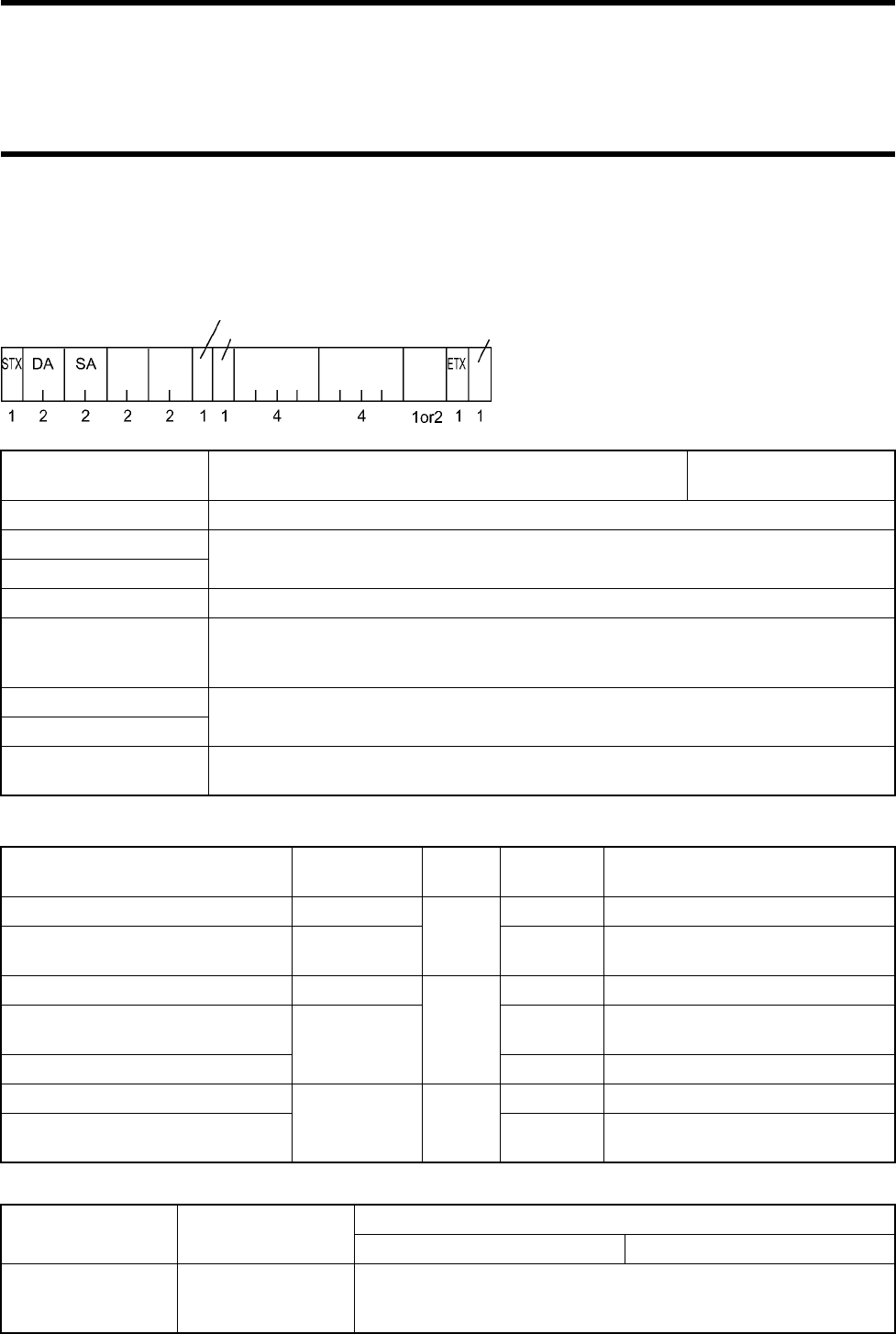
5-7 Tag Communication Command
5-27
5-7-6 Data Fill
Writes the same data into a specified area of a tag.
<Command Format> * A figure below shows the number of characters.
Command code and communication designation
Start address, number of read bytes
DA Destination (antenna) station number. "00" to "31". This can
be modified in "5-9-8 Station Number Setting". Initial value "00"
SA
Source (host device) station number. "80" to "89". If only one host device is used, specify "80".
Command code Specify according to the table below.
Communication designation
Split flag Specify "A".
Code designation Specify whether data read out of a tag is ASCII code or hexadecimal code.
A: ASCII code
H: Hexadecimal code
Start address Specify according to the table below.
Number of read bytes
Data If the data designation is ASCII code, one character.
If the data designation is hexadecimal code, two characters.
Command Tag status
after execution
Command
code
Communica-
tion designation
Remarks
Single Trigger Sleep
F3
SU
Single Trigger Standby WU Any other command can be exe-
cuted to the tag immediately after it.
Single Auto Sleep
F6
SU
Single Auto Standby WU Any other command can be exe-
cuted to the tag immediately after it.
Polling Single Auto CU
Single Repeat
Sleep F9
SU FIFO
Polling Single Repeat RU For a query command of polling,
refer to "5-8-3 Request To Respond".
Read content Start address Number of written bytes
ASCII code Hexadecimal code
Data
Reading start address
("0000" to "1FFF")
* Hexadecimal number
Specify the number of written bytes
("0001" to "2000")
* Hexadecimal number
Split flag
Command
code Communica-
tion designa-
tion
Code designation
Start address Number of
written bytes
(BCC)
* It can be specified whether BCC is
enabled or disabled.
Data
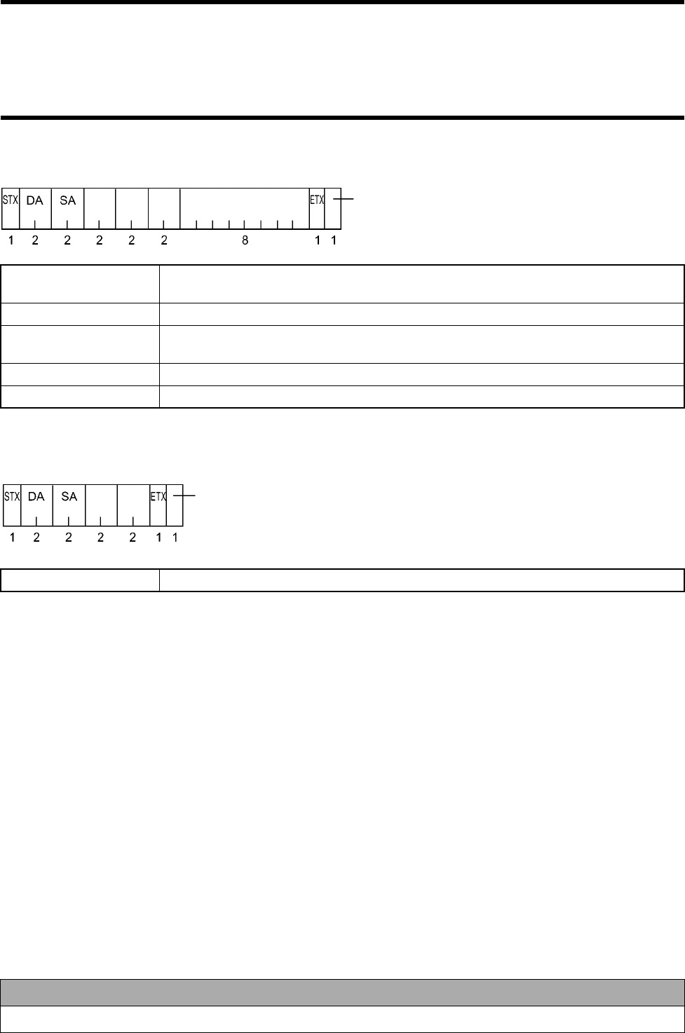
5-7 Tag Communication Command
5-28
<Response Format> * A figure below shows the number of characters.
<Poling Response Format> * A figure below shows the number of characters.
Response immediately after a polling command is issued.
DA Destination (host device) station number. * In the command format, the destination is an
antenna.
SA Source (antenna) station number.
Termination code "00": For a normal end. For any other termination codes, refer to "5-10 Termination Code
List".
Response number Fixed to "01".
ID code ID code of tag. This is inherent to tag and cannot be rewritten.
Termination code Fixed to "00".
Correct Usage
For an available range of number of written bytes, check the ID tag memory capacity.
Command
code Termination
code Response
number
ID code
(BCC)
* It can be specified whether BCC is enabled or disabled.
Command
code Termination
code
(BCC)
* It can be specified whether BCC is enabled or disabled.
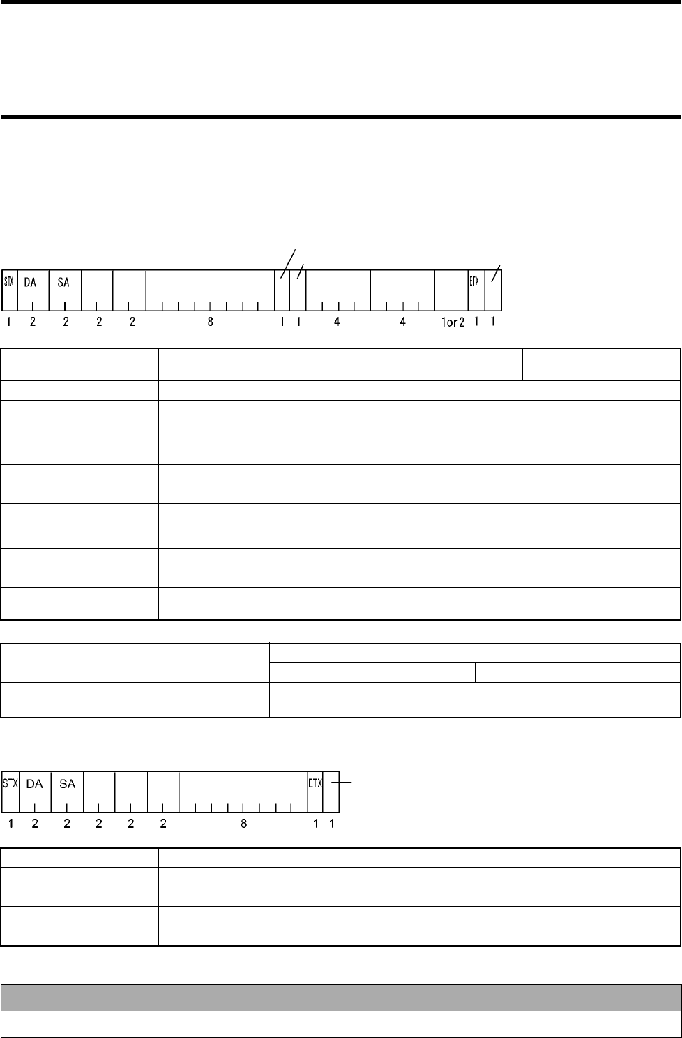
5-7 Tag Communication Command
5-29
5-7-7 Tag Designation Data Fill
Writes fixed data into a particular ID tag.
<Command Format> * A figure below shows the number of characters.
Start address, number of read bytes
<Response Format> * A figure below shows the number of characters.
DA Destination (antenna) station number. "00" to "31". This can be
modified in "5-9-8 Station Number Setting". Initial value "00"
SA
Source (host device) station number. "80" to "89". If only one host device is used, specify "80".
Command code F3: Single Trigger
Communication designa-
tion Gives communication designation to a tag.
SN: A tag will be in a sleep state after execution.
WN: A tag will be in a standby state after execution.
ID code Specify an ID code of a particular tag.
Split flag Specify "A".
Code designation Specify whether data read out of a tag is ASCII code or hexadecimal code.
A: ASCII code
H: Hexadecimal code
Start address Specify according to the table below.
Number of read bytes
Data If the data designation is ASCII code, one character.
If the data designation is hexadecimal code, two characters.
Read content Start address Number of written bytes
ASCII code Hexadecimal code
Data Reading start address
("0000" to "1FFF") Specify the number of written bytes
("0001" to "2000")
DA
Destination (host device) station number. * In the command format, the destination is an antenna.
SA Source (antenna) station number.
Termination code
"00": For a normal end. For any other termination codes, refer to "5-10 Termination Code List".
Response number Fixed to "01".
ID code ID code of tag. This is inherent to tag and cannot be rewritten.
Correct Usage
For an available range of number of written bytes, check the ID tag memory capacity.
Split flag
Command
code
Code designation
Start address Number of
written bytes
(BCC)
* It can be specified whether BCC
is enabled or disabled.
Commu-
nication
designation
ID code data
Command
code Termination
code Response
number
ID code
(BCC)
* It can be specified whether BCC is enabled or disabled.
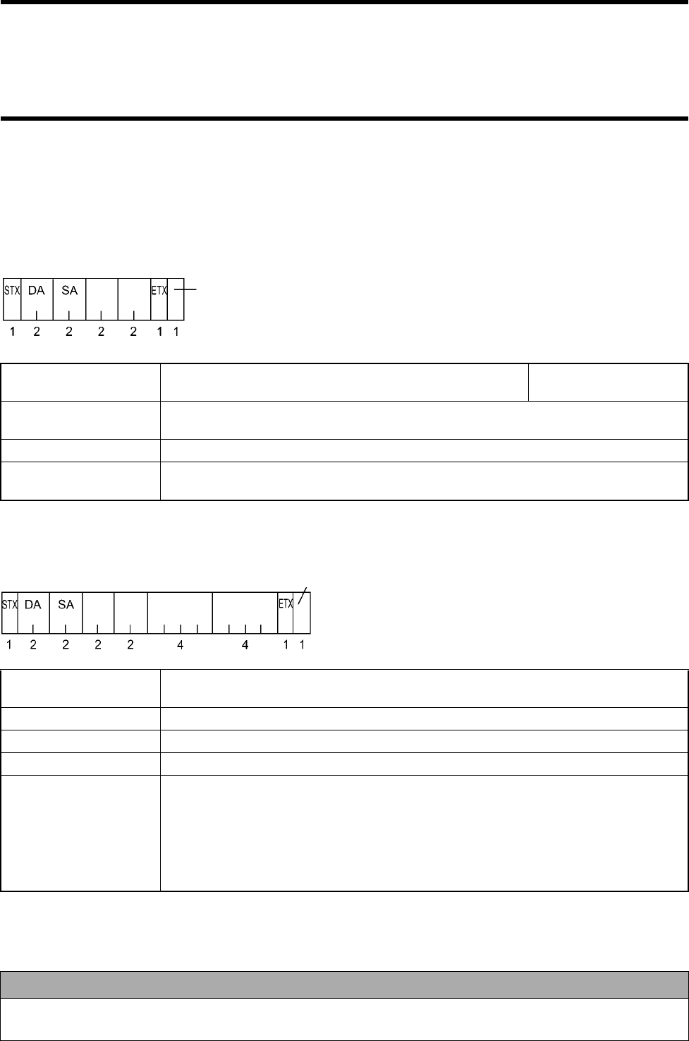
5-7 Tag Communication Command
5-30
5-7-8 Communication Test
To check a radio wave environment, data (256 bytes) is communicated 256 times between the antenna and tag and the communication
status is output. A total of 128 kbytes of data is communicated in two ways. So, it takes a few seconds to execute this text.
The communication is retried in active use. However, the communication is not retried in a communication test.
<Command Format> * A figure below shows the number of characters.
<Response Format> * A figure below shows the number of characters.
DA Destination (antenna) station number. "00" to "31". This can
be modified in "5-9-8 Station Number Setting". Initial value "00"
SA Source (host device) station number. "80" to "89". If only one host device is used, specify
"80".
Command code T0: Single Trigger
Communication designa-
tion SU: A tag will be in a sleep state after execution.
DA Destination (host device) station number. * In the command format, the destination is an
antenna.
SA Source (antenna) station number.
Termination code Fixed to "00".
Number of communications
Fixed to "0256".
Radio wave environment
value "0000" to "0256" (decimal number).
A smaller radio wave environment value shows a better radio wave environment.
(The radio wave environment value is the number of failed communication of total 256 com-
munications. In the communication test, communication is not retried. However, the com-
munication is retried when the communication fails in an actual operation. If the radio wave
environment value is 50 or less, a communication error does not occur in an actual opera-
tion.)
Correct Usage
Check your radio wave environment with this command before operating your system. We recommend you to set the
radio wave environment value to 50 or less.
Command
code Termination
code
(BCC)
* It can be specified whether BCC is enabled or disabled.
Command
code Termination
code
Number of commu-
nications
(BCC)
* It can be specified whether BCC is enabled or disabled.
Radio wave envi-
ronment value
5-31
5-8-1 Auto Repeat Cancel
Cancels the Auto or Repeat command during the execution of the command. Then, an antenna waits for a command.
<Command Format> * A figure below shows the number of characters.
<Response Format> * A figure below shows the number of characters.
DA Destination (antenna) station number. "00" to "31". This can
be modified in "5-9-8 Station Number Setting". Initial value "00"
SA Source (host device) station number. "80" to "89". If only one host device is used, specify
"80".
Command code C2
DA Destination (host device) station number. * In the command format, the destination is an
antenna.
SA Source (antenna) station number.
Termination code Fixed to "00".
Command
code
(BCC)
* It can be specified whether BCC is enabled or disabled.
Command
code Termination
code
(BCC)
* It can be specified whether BCC is enabled or disabled.
5-8 Antenna Operation Command
5-8 Antenna Operation Command
5-32
5-8-2 Reset
Resets an antenna. It takes approximately 2 seconds to reset.
Resetting:
• Clears data read out of a tag at polling. A response is not returned by the Request to Response (H0) command.
• Clears the immediately preceding response. A response is not returned by the Request to Retransmit (H1) command.
• Changes the Radio Wave Transmission ON mode into the OFF mode.
• Enables the host communication condition setting (Section 5-9-7) and station number setting (Section 5-9-8) commands.
<Command Format> * A figure below shows the number of characters.
<Response Format>
There is no response format.
DA Operation mode Destination (antenna) station number. "00" to "31". This
can be modified in "5-9-8 Station Number Setting". Initial value "00"
Setting mode "99"
SA Source (host device) station number. "80" to "89". If only one host device is used, specify "80".
Command code C0
Command
code
(BCC)
* It can be specified whether BCC is enabled or disabled.

5-8 Antenna Operation Command
5-33
5-8-3 Request to Respond
Requests a tag to respond during the execution of a polling command.
<Command Format> * A figure below shows the number of characters.
<Response Format> * A figure below shows the number of characters.
• If a tag responds:
Returns a response from the tag, which received at polling.
• If a tag does not respond:
DA Destination (antenna) station number. "00" to "31". This can
be modified in "5-9-8 Station Number Setting". Initial value "00"
SA Source (host device) station number. "80" to "89". If only one host device is used, specify
"80".
Command code H0
DA Destination (host device) station number. * In the command format, the destination is an
antenna.
SA Source (antenna) station number.
Termination code Fixed to "74".
Command
code
(BCC)
* It can be specified whether BCC is enabled or disabled.
Command
code Termination
code
(BCC)
* It can be specified whether BCC is enabled or disabled.
5-8 Antenna Operation Command
5-34
5-8-4 Request to Retransmit
Request to retransmit the immediately preceding response.
<Command Format> * A figure below shows the number of characters.
<Response Format> * A figure below shows the number of characters.
• If there is an immediately preceding response, such response is returned.
• If there is no immediately preceding response (it is not stored in an antenna), the following response is returned.
DA Destination (antenna) station number. "00" to "31". This can
be modified in "5-9-8 Station Number Setting". Initial value "00"
SA Source (host device) station number. "80" to "89". If only one host device is used, specify
"80".
Command code H1
DA Destination (host device) station number. * In the command format, the destination is an
antenna.
SA Source (antenna) station number.
Termination code Fixed to "15".
Command
code
(BCC)
* It can be specified whether BCC is enabled or disabled.
Command
code Termination
code
(BCC)
* It can be specified whether BCC is enabled or disabled.
5-35
5-9-1 Radio Wave Transmission ON/OFF
Specifies the radio wave transmission OFF mode and radio wave transmission ON mode of an antenna. (Refer to (2) in Section 5-2-3.)
This command can be used in the operation mode, not in the setting mode. (Refer to Section 5-1 and (3) in Section 5-4.)
When the power supply is reset or a reset command is executed, the radio wave transmission OFF mode which is initial value is enabled.
<Command Format> * A figure below shows the number of characters.
<Response Format> * A figure below shows the number of characters.
DA Destination (antenna) station number. "00" to "31". This can
be modified in "5-9-8 Station Number Setting". Initial value "00"
SA Source (host device) station number. "80" to "89". If only one host device is used, specify
"80".
Command code A0: Specifies the radio wave transmission OFF mode.
A1: Specifies the radio wave transmission ON mode. Initial value is the radio
wave transmission OFF
mode.
DA Destination (host device) station number. * In the command format, the destination is an
antenna.
SA Source (antenna) station number.
Termination code Fixed to "00".
Command
code
(BCC)
* It can be specified whether BCC is enabled or disabled.
Command
code Termination
code
(BCC)
* It can be specified whether BCC is enabled or disabled.
5-9 Antenna Setting Command
5-9 Antenna Setting Command
5-36
5-9-2 Communication Range Mode and Radio Wave Channel Selection
Selects a communication range mode and radio wave channel of an antenna. A communication range mode can be changed by selecting
the communication range mode. Frequency is changed by selecting the radio wave channel and interference between antennas and
interference caused by any other radio equipment are prevented.
<Command Format> * A figure below shows the number of characters.
<Response Format> * A figure below shows the number of characters.
DA
Operation mode
Destination (antenna) station number. "00" to "31". This
can be modified in "5-9-8 Station Number Setting".
Initial value "00"
Setting mode "99"
SA Source (host device) station number. "80" to "89". If only one host device is used, specify "80".
Command code A4: Selects a communication range mode.
A5: Selects a radio wave channel.
Set value
For the command A4
L: Communication range 2 m mode
H: Communication range 5 m mode
Initial value of com-
munication range
L (2 m mode)
For the command A5
"0" to "9": Divides the frequency range 2437.5 to 2462.5 MHz into ten. Initial value of radio
wave channel
Channel 5 (A value of
center)
DA Destination (host device) station number. * In the command format, the destination is an
antenna.
SA Source (antenna) station number.
Termination code Fixed to "00".
Command
code
(BCC)
* It can be specified whether BCC is enabled or disabled.
Set value
Command
code Termination
code
(BCC)
* It can be specified whether BCC is enabled or disabled.

5-9 Antenna Setting Command
5-37
5-9-3 Radio Wave Output Status Read
Selects a communication range mode and radio wave channel of an antenna.
<Command Format> * A figure below shows the number of characters.
<Response Format> * A figure below shows the number of characters.
DA Operation mode Destination (antenna) station number. "00" to "31". This
can be modified in "5-9-8 Station Number Setting". Initial value "00"
Setting mode "99"
SA Source (host device) station number. "80" to "89". If only one host device is used, specify "80".
Command code A6
DA Destination (host device) station number. * In the command format, the destination is an
antenna.
SA Source (antenna) station number.
Termination code Fixed to "00".
Communication range L: Communication range 2 m mode
H: Communication range 5 m mode
Radio wave channel Divides the frequency range 2437.5 to 2462.5 MHz into ten.
Command
code
(BCC)
* It can be specified whether BCC is enabled or disabled.
Command
code Termination
code
(BCC)
* It can be specified whether BCC is enabled or disabled.
Radio wave channel
Communication range
5-9 Antenna Setting Command
5-38
5-9-4 Setting of Time to Wait Tag
Specifies time to wait for communication with a tag after issue of command when executing Auto or Repeat command. Initial value is
infinity (0000).
For the Auto command, when the waiting time for tag has been passed, the antenna returns the no-tag error response 72 and discontinues
the Auto command. For the Repeat command, when the waiting time for tag has been passed, the antenna returns the no-tag error
response 72 and continues the Repeat command.
<Command Format> * A figure below shows the number of characters.
<Response Format> * A figure below shows the number of characters.
DA Operation mode Destination (antenna) station number. "00" to "31". This
can be modified in "5-9-8 Station Number Setting". Initial value "00"
Setting mode "99"
SA Source (host device) station number. "80" to "89". If only one host device is used, specify "80".
Command code T4
Set value "0000": Infinity.
"0001" to "9999": A left value x 100 msec. Initial value
"0000": Infinity
DA Destination (host device) station number. * In the command format, the destination is an
antenna.
SA Source (antenna) station number.
Termination code Fixed to "00".
Command
code
(BCC)
* It can be specified whether BCC is ena
b
Set value
Command
code Termination
code
(BCC)
* It can be specified whether BCC is enabled or disabled.
5-9 Antenna Setting Command
5-39
5-9-5 Command Data Response Time Setting
Specifies a minimum time until an antenna returns a response after receiving a command and a minimum time until the antenna returns
the next response after returning the last response. Initial value is 10 msec. (Refer to "Correct Usage" of (2) in Section 4-2-2.)
<Command Format> * A figure below shows the number of characters.
<Response Format> * A figure below shows the number of characters.
DA Operation mode Destination (antenna) station number. "00" to "31". This
can be modified in "5-9-8 Station Number Setting". Initial value "00"
Setting mode "99"
SA Source (host device) station number. "80" to "89". If only one host device is used, specify "80".
Command code H4
Command
response Specifies a minimum time until an antenna returns a response after receiving
a command."00" to "99": A left value x 1 msec. Initial value "10":
10 msec
Data response Specifies a minimum time until the antenna returns the next response after
returning the last response, if the antenna returns several responses.
"00" to "99": A left value x 1 msec.
Initial value "10":
10 msec
DA Destination (host device) station number. * In the command format, the destination is an
antenna.
SA Source (antenna) station number.
Termination code Fixed to "00".
Command
code
(BCC)
* It can be specified whether BCC is enabled or disabled.
Command
response Data
response
Command
code Termination
code
(BCC)
* It can be specified whether BCC is enabled or disabled.
5-9 Antenna Setting Command
5-40
5-9-6 Read Data Length Setting
Specifies the maximum number of read bytes which can be returned as one response by the Read command. If the conditions of com-
munication with a host device is good, specify a large number. If not, specify a small number.
For example, if you try to read 2048 bytes of data, of which read data length is 256 bytes, by the Read command, the antenna returns a
response 8 times.
<Command Format> * A figure below shows the number of characters.
<Response Format> * A figure below shows the number of characters.
DA Operation mode Destination (antenna) station number. "00" to "31". This
can be modified in "5-9-8 Station Number Setting". Initial value "00"
Setting mode "99"
SA Source (host device) station number. "80" to "89". If only one host device is used, specify "80".
Command code H3
Number of read
bytes "0020" to "4000": Hexadecimal notation. The unit is byte. Initial value
"0100" 256 bytes
DA Destination (host device) station number. * In the command format, the destination is an
antenna.
SA Source (antenna) station number.
Termination code Fixed to "00".
Command
code
(BCC)
* It can be specified whether BCC is enabled or disabled.
Number of read
bytes
Command
code Termination
code
(BCC)
* It can be specified whether BCC is enabled or disabled.
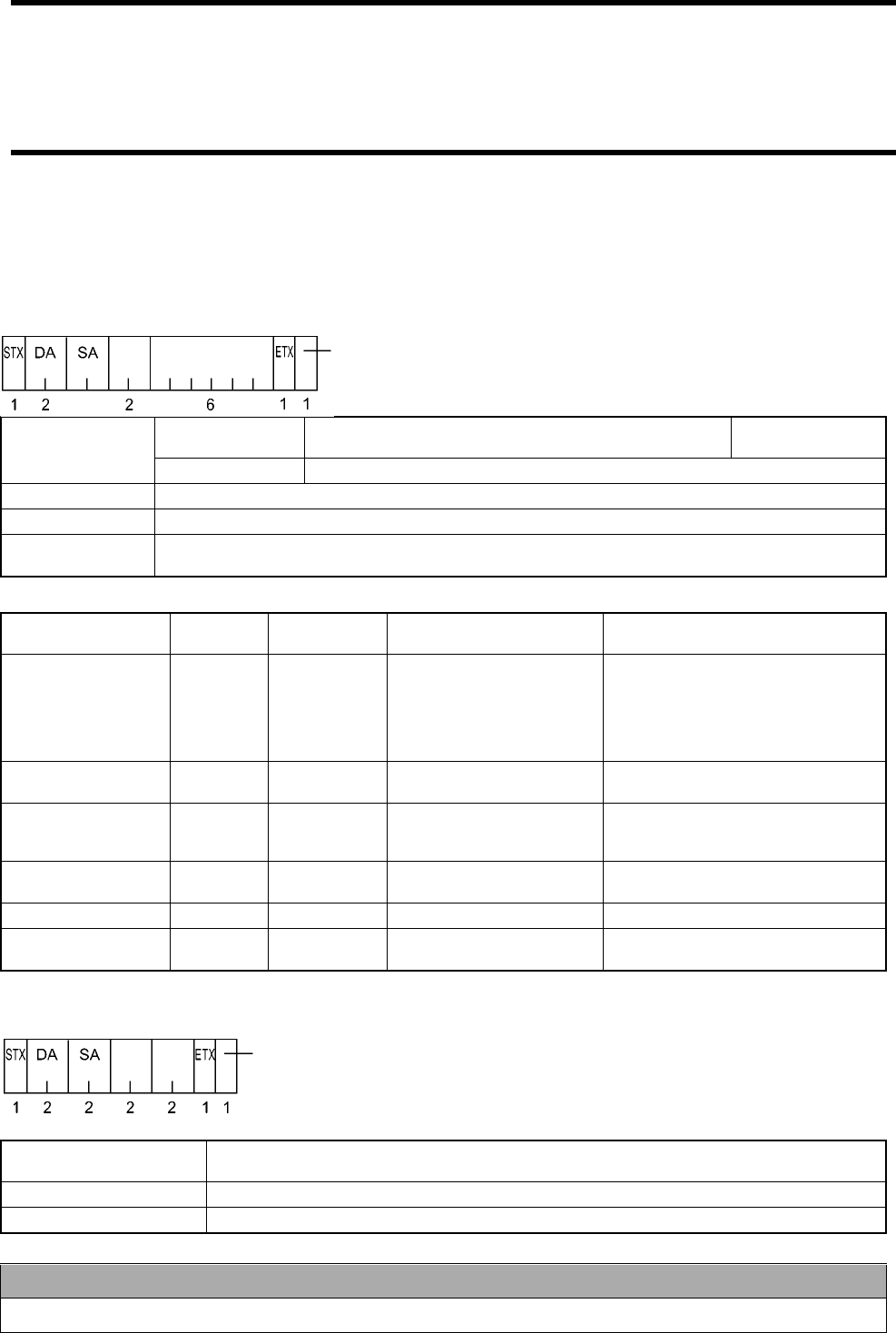
5-9 Antenna Setting Command
5-41
5-9-7 Host Communication Condition Setting
Specifies the conditions of communication between a host device and antenna. To enable this setting, you must issue a command and
then issue the reset command (Section 5-8-2) or reset the power supply.
<Command Format> * A figure below shows the number of characters.
<Set Character String> Specify all together as shown below.
<Response Format> * A figure below shows the number of characters.
DA Operation mode Destination (antenna) station number. "00" to "31". This
can be modified in "5-9-8 Station Number Setting". Initial value "00"
Setting mode "99"
SA Source (host device) station number. "80" to "89". If only one host device is used, specify "80".
Command code H5
Communication
condition data As described below.
Parameter Name Byte
Length Set Value Meaning Initial value
Communication condition in the setting mode
Transmission speed 1
1
2
3
4
5
6
4.8 kbps
9.6 kbps
19.2 kbps
38.4 kbps
57.6 kbps
115.2 kbps
"2" = 9.6 kbps
Data length 1 7
87 bits
8 bits "7" = 7 bits
Parity 1 E
O
N
Even
Odd
Nil "E" = Even
Stop bit 1 1
21 bit
2 bits "2" = 2 bits
Communication mode 1 0 Fixed "0"
BCC enabled/dis-
abled 10
1BCC disabled
BCC enabled "0" = BCC disabled
DA Destination (host device) station number. * In the command format, the destination is an
antenna.
SA Source (antenna) station number.
Termination code Fixed to "00".
Correct Usage
If the data length is set to 7 bites, alphanumerical character only can be used.
Command
code
(BCC)
* It can be specified whether BCC is enabled or disabled.
Communication
conditions
Command
code Termination
code
(BCC)
* It can be specified whether BCC is enabled or disabled.
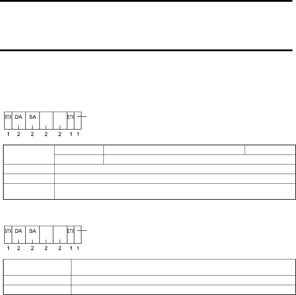
5-9 Antenna Setting Command
5-42
5-9-8 Station Number Setting
Specifies a station number as a radio station for an antenna. To enable this setting, you must issue a command and then issue the reset
command (Section 5-8-2) or reset the power supply.
<Command Format> * A figure below shows the number of characters.
<Response Format> * A figure below shows the number of characters.
DA Operation mode Destination (antenna) station number. "00" to "31". Initial value "00"
Setting mode "99"
SA Source (host device) station number. "80" to "89". If only one host device is used, specify "80".
Command code H6
New station num-
ber "00" to "31"
DA Destination (host device) station number. * In the command format, the destination is an
antenna.
SA Source (antenna) station number.
Termination code Fixed to "00".
Command
code
New sta-
tion num-
ber
(BCC)
* It can be specified whether BCC is enabled or disabled.
Command
code Termination
code
(BCC)
* It can be specified whether BCC is enabled or disabled.
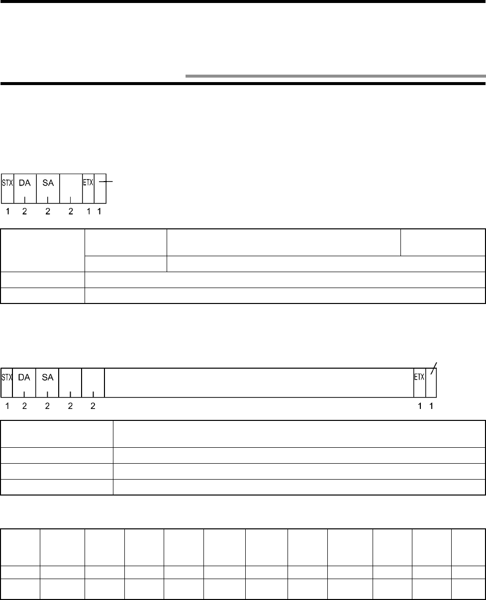
5-43
5-9-9 Setting Read
Reads antenna attribute, setting type, date of production, etc.
<Command Format> * A figure below shows the number of characters.
<Response Format> * A figure below shows the number of characters.
Data about Setting Read (M2)
Note) The radio wave transmission OFF time and the number of retries are fixed.
DA Operation mode Destination (antenna) station number. "00" to "31". This
can be modified in "5-9-8 Station Number Setting". Initial value "00"
Setting mode "99"
SA Source (host device) station number. "80" to "89". If only one host device is used, specify "80".
Command code M2
DA Destination (host device) station number. * In the command format, the destination is an
antenna.
SA Source (antenna) station number.
Termination code Fixed to "00".
Data As described below.
Data
Name
Radio Wave
Transmis-
sion OFF
Time
Commu-
nication
Range
Mode
Radio
Wave
Channel
Waiting
Time for
Tag
Com-
mand
Response
Time
Data
Response
Time
Read
Data
Length
Communi-
cation
Condition
Station
Number
Number
of
Retries
Data "0000" "H/L" * "eeee" "nn" "ii" "kkkk" "abcdef" "ff" "m"
Number of
characters
4 114 2 2 4 6 21Total 27
Command
code
(BCC)
* It can be specified whether BCC is enabled or disabled.
Command
code Termination
code
(BCC)
* It can be specified whether BCC is enabled or disabled.
Data
5-10 Termination Code List

5-10 Termination Code List
5-44
The meanings of termination code of response are described below.
Type
Termination Code
Name Description
Normal end "00" Normal end Command execution has ended correctly.
"15" Non-executable There is no immediately preceding response at
Request to Retransmit (Section 5-8-4).
"72" Multi Trigger ended Multi Trigger ended.
"74" No polling tag communication Communication with a tag has not yet been ended
by a polling command.
Host
communication
error
"10" Parity error A parity error has occurred in any character of
command.
"11" Framing error A framing error has occurred in any character of
command.
"12" Overrun error An overrun error has occurred in any character of
command.
"13" BCC error BCC of received command is invalid.
"14" Format error A format of a command received properly is incor-
rect.
"15" Non-executable A received command cannot be executed in a
current mode.
"18" Frame length error ETX more than 8220 characters is not received
after STX is received.
Communication
error "70" Communication error An error has occurred during the communication
with a tag and the communication cannot be com-
pleted correctly.
"71" Verification error Writing was not performed correctly. An data
error was detected at writing verification.
"72" No-tag error There is no tag in front of a tag when the Trigger
command is executed. Waiting time for a tag has
passed in the Auto Repeat command.
"7A" Address error Memory address of inexistent ID tag was desig-
nated.
"7B" Battery voltage low Voltage of battery built in an ID tag dropped.
"7D" Write Protect error Something was written into a write-protected
page.
System error "92" Antenna failure Failure of radio wave transmitter, etc. or an error
in a program in an antenna.
"93" Tag memory error An ID tag data error was detected at data reading.
Correct Usage
When a communication error or verification error has occurred at the execution of Write command, data of address des-
ignated by the command may be rewritten partially or completely.
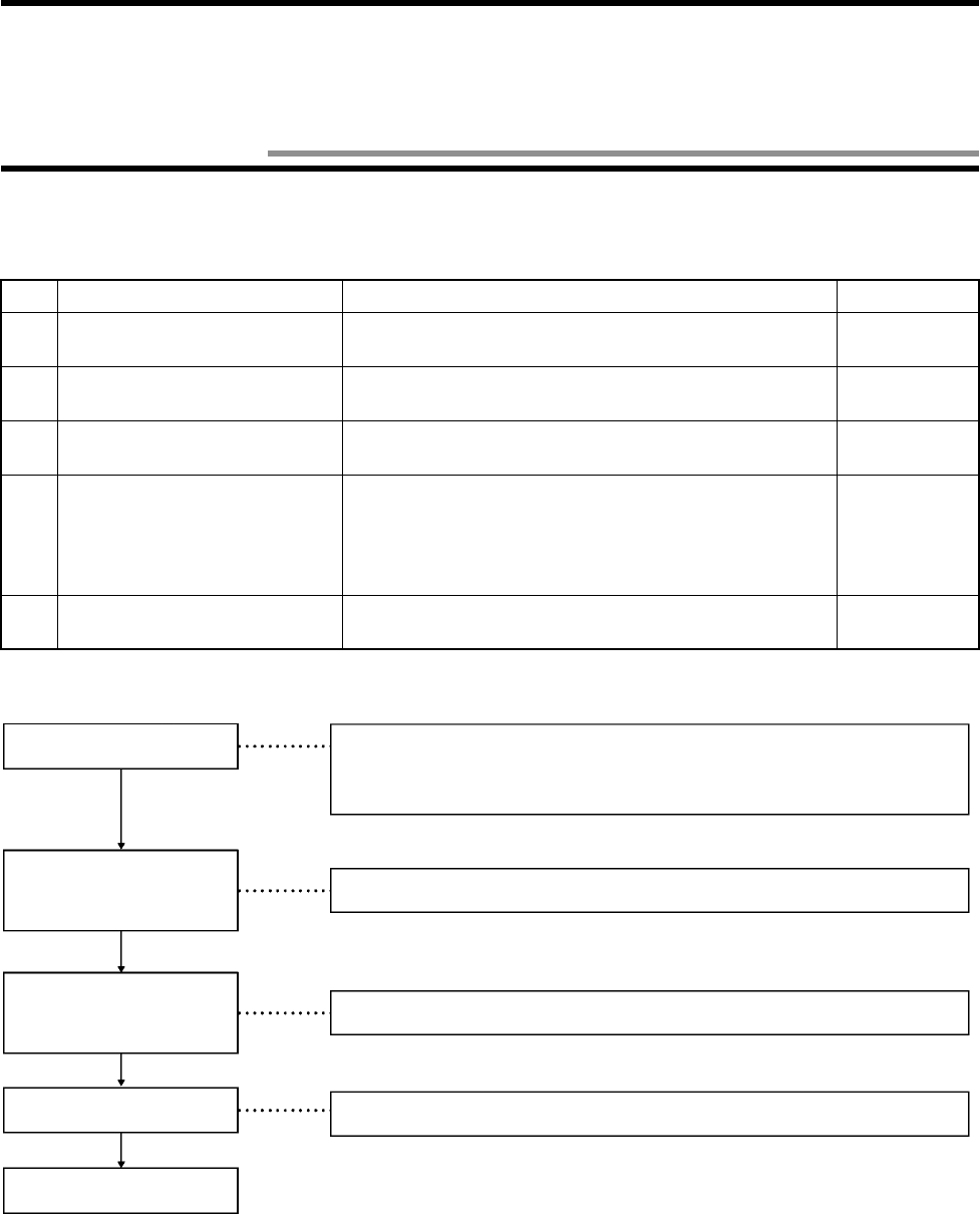
6-1
♦
♦♦
♦ Items to be checked
Before performing a trial operation, check the following items:
♦
♦♦
♦ Trial operation procedure
♦
♦♦
♦ Simplified communication test
The communication between an antenna and tag can be tested without connection to a host device. Use this test to check the location of
antenna and tag. For how to operate, refer to Section 3-4.
♦
♦♦
♦ Communication test
The connection to a host device is made and the "Communication Test" command is sent from the host device to an antenna. Commu-
nication cable connection, communication processing, communication status between the antenna and tag can be checked. For how to
operate, refer to Section 3-5.
No. Items to be checked Checking Page
1 Installation environment of
antenna and tag Whether the installation environment is suitable. Section 4-1-1
2 Installation of antenna and tag Whether the antenna and tag are installed correctly. Sections 4-1-2
and 4-1-3
3 Connection of antenna and dedi-
cated cable Whether the connector is connected properly. Section 4-1-4
4 Connection to host device • Whether RS-232C, RS-422A and RS-485 are connected
properly.
• Whether connected to 24 VDC power supply.
• Whether installed.
• Whether "+P" and "-P" are connected.
Section 4-2
5 Installation of link unit for RS-
422A and RS-485 Whether the link unit is installed correctly. Section 4-3
Turns on the power supply.
Simplified communication test
Communication test
Trial operation for system.
End.
• Check the power supply voltage and power supply terminal connection.
• Check whether the antenna indicator POWER LED turns on.
Check the communication between an antenna and tag without connection to a host
device (or with connection to the host device).
Check the communication between a host device and antenna and between an antenna and tag.
Check a total system operation with an actual command.
Chapter 6 From Startup to Run
6-1 Trial Operation
6-2
To shorten the system down time when an error has occurred in an antenna, you can diagnose through an indicator.
♦
♦♦
♦ At a normal operation
: Turns on. : Turns on only at radio wave transmission or communication. : Turns off.
♦
♦♦
♦ When an error has occurred
: Turns on. : Turns on at communication. : Blinks. : Turns off.
Antenna Indicator
Indication
PCHT
Power
supply
Radio wave
transmission
Host trans-
mission Tag trans-
mission
Power is supplied to an antenna, but no communication is
made to a tag.
Simplified communication function of the setting mode works.
Indicator C: means waiting for a tag and means communication with a tag.
Executes a command of Trigger and communicates with a tag.
Executes a command of Auto or Repeat and waits for a tag.
Executes a command of Auto or Repeat and communicates
with a tag.
Trouble
Antenna Indicator
Estimated Cause Countermeasures
PCHT
Power
supply
Radio wave
transmission
Host
communication
Tag
transmission
Antenna does not
respond
• An error in power supply
to an antenna
• Antenna failure.
• Check the power supply voltage.
• Replace the antenna with a new
one.
• Antenna failure. • Replace the antenna with
a new one.
• An error communication
with a host device.
• Check the communication
line to the host device.
——
Tag does not
respond —
• A tag is in a sleep state.
• Tag failure.
• Antenna failure.
• Take the tag out of the commu-
nication area and return to the
area again.
• Replace the tag with a new one.
• Replace the antenna with a new
one.
6-2 Diagnosis Function

6-3
Refer to "5-10 Termination Code List" also.
♦
♦♦
♦ Host communication error
♦
♦♦
♦ Communication error
♦
♦♦
♦ System error
Error Code Name Check Points
"10" Parity error • Checking the setting about conditions of communication with a host device.
→ Refer to Sections 5-9-7 and 5-9-9.
• Wiring of RS-232C, RS-422A and RS-485 (Example: Terminating resis-
tance and influence of ambient noise)
→ Refer to Sections 4-2, 4-3 and 6-3.
"11" Framing error
"12" Overrun error
"13" BCC error • How to calculate BCC → Refer to Section 5-3.
• Wiring of RS-232C, RS-422A and RS-485 (Example: Terminating resis-
tance and influence of ambient noise)
→ Refer to Sections 4-2, 4-3 and 6-3.
"14" Format error
• Format of command (Example: Applicable characters and position of STX/ETX)
→ Refer to Sections 5-7 to 5-9.
"18" Frame length error
Error Code Name Check Points
"70" Communication error • Distance between an antenna and tag, and tag movement speed.
• Wiring of FG, power cable, etc. (Influence of ambient noise)
• Noise environment around antenna. (FG ground of devices, shield and loca-
tion change)
→ Refer to Sections 4-2, 4-3 and 6-3.
"71" Verification error • Noise environment around antenna. (FG ground of devices, shield and loca-
tion change)
→ Refer to Sections 4-2, 4-3 and 6-3.
"72" No existence error • Distance between an antenna and tag, and tag movement speed.
"7A" Address error • Designation of address/number of bytes of executed command.
• Tag memory capacity and applicable address range.
→ Refer to Section 5-7.
"7B" Battery voltage low • Traffic, ambient temperature and battery life.
→ Section 2-2-6.
"7D" Write Protect error • Setting of Write Protect information.
→ Section 3-6.
• Designation of address/number of bytes of executed command.
→ Refer to Section 5-7.
Error Code Name Description
"92" Antenna failure • Antenna indicator.
→ Section 6-2.
"93" Tag memory error • Take out of the communication area, return to the area again and check the
termination code.
If the same error occurs, replace a tag with a new one.
6-3 Error List
6-4
The six main causes of troubles in V690 Series are as follows:
• Influence of installation environment . . . . . . Refer to Section 4-1-1.
• Influence of noise. . . . . . . . . . . . . . . . . . . . . . Take countermeasures against noise.
• External device failure
• Antenna failure
• Link unit failure
• Cable failure
• Tag failure
• Others
♦
♦♦
♦ Influence of noise
If an error occurs in an operation of your system, take suitable countermeasures against noise referring to the table below.
•
••
•Improvement of grounding •
••
•Countermeasure against power supply noise
No. Trouble Estimated Cause Countermeasures
1 Trouble caused in large-capacity
motor, transformer, capacitor, etc.
when the power supply turns on.
Instantaneous voltage drop in
power supply system due to inrush
current of large-capacity load.
• Increase the capacity of power supply equip-
ment and of power cable.
Common mode noise due to cause
above.
• Supply the power through 1:1 non-contact
insulation transformer.
• Do not use together with ground to any other
large-capacity load. Perform ground of Class
D (conventional Class III) only.
2 Trouble caused at irregular inter-
vals. Noise superposed on the power
supply.
• Supply the power through 1:1 non-contact
insulation transformer or noise filter.
• Do not use together with ground to any other
large-capacity load. Perform grounding of
Class D (conventional Class III) only.
Influence of space noise.
• Keep 1 meter or more away from an antenna
if there are PC, AD adapter for PC, switching
power supply, programmable terminal, motor,
proximity switch, etc.
Correct Usage
One meter away from a space noise generating source is a reference value. Depending on a noise generating source,
more than one meter must be away from it. Execute the communication test to check.
Other
device Antenna Other
device Antenna
Grounding of
Class D
Li
ne
filt
er
Twist it. Not to be parallel
with any other power line, etc.
Antenna
6-4 Errors and Countermeasures
. . . . . . . . . . . . . Must be repaired.

6-5
To maintain V690 Series in the best condition, you need to inspect it daily or periodically. V690 Series mainly consists of semiconduc-
tor components which have a long life. However, the following malfunctions are expected depending on the service environment or
operating condition.
(1) Deterioration of element due to over-voltage or over-current.
(2) Deterioration of element due to long-term stress arisen from use in a high-temperature site.
(3) Deterioration of insulation or imperfect contact of connector due to unsuitable temperature or dust.
(4) Imperfect contact of connector or corrosion of element due to corrosive gas.
♦
♦♦
♦Inspection item
No. Inspection Item Inspection Criterion Remarks
1 Fluctuation of power sup-
ply voltage (1) Check at a terminal block of
power supply whether the
criterion is satisfied.
Within the specifications
for power supply voltage. Tester.
(2) Check whether instanta-
neous power failure occurs
frequently and whether volt-
age fluctuates considerably
Within a allowable voltage
fluctuation range. Power supply
analyzer.
2 Ambient environment
(1) Temperature
(2) Humidity
(3) Vibration or impact
(4) Dust
(5) Corrosive gas
(1) Within the specifications.
(2) Within the specifications.
(3) Influence of vibration or
impact of machines.
(4) Dust or foreign material.
(5) Discoloration or corrosion in
a metal part.
(1) Within the specifications.
(2) Within the specifications.
(3) Within the specifications.
(4) Neither dust nor foreign
material is acceptable.
(5) Neither discoloration nor
corrosion is acceptable.
Lowest tempera-
ture thermometer.
Hygrometer.
3 Panel conditions
(1) Whether the panel is
ventilated.
(2) Whether packing mate-
rial of sealed structure
is deteriorated.
(1) Check whether natural ven-
tilation, forced ventilation
and cooling are performed.
(2) Check whether packing
material in the panel is
removed or damaged.
(1) Ventilation must be
made properly. Tem-
perature must be within
-10 and +55°C.
(2) Any damage is unac-
ceptable.
—
4 Power supply for I/O
(1) Voltage fluctuation
(2) Ripple
Check at a terminal block of
every I/O section whether crite-
rion is satisfied.
Within the specifications. Tester.
Oscilloscope.
5 Mounting state (1) Whether every device is
fixed tightly. Every device must be fixed
tightly. —
(2) Whether every connector is
inserted completely. Every connector must be
locked properly and fixed
by screws. —
(3) Whether terminal block
screws are tightened com-
pletely.
The terminal block screws
must be tightened com-
pletely. —
(4) Whether wire is not dam-
aged. The wire must not be dam-
aged. —
(5) Whether condition between
a tag and antenna is within
the specifications.
The condition must be with
in the specifications. —
(6) Whether grounding com-
plies with the Class D (con-
ventional Class III). —
6-5 Maintenance and Inspection
6-6
When an error has occurred, grasp the situation fully and check according to the flow below ("Trial operation procedure" in Section 6-
1).
Turn on the power supply
Simplified communication test
Simplified communication test
OK?
Antenna operation check list
Host device connection check list
Communication test
Communication with host
device OK?
Tag communication check list (1)
Communication with tag
OK?
Trial operation with system
Tag communication check list (2)
Ambient environment check list
Trial operation OK?
Correct
Wrong
Correct
Wrong
Correct
Wrong
Correct
Wrong
Correct
6-6 Troubleshooting

6-6 Troubleshooting
6-7
♦
♦♦
♦ Antenna operation check list
♦
♦♦
♦ Host device connection check list
♦
♦♦
♦ Tag communication check list (1)
♦
♦♦
♦ Tag communication check list (2)
Check Point Countermeasures
! Whether the antenna indicator P (power supply) turns
on. • Check 24 VDC power supply line.
• Turn ON the antenna power supply switch of link unit.
• Check the power supply voltage.
• Replace the antenna with a new one.
! Whether the antenna indicator C (radio wave transmis-
sion) turns on. • Enable the setting mode. → Refer to Section 3-4.
• Replace the antenna with a new one.
Check Point Countermeasures
! Connection of a host communication cable, connector
and link unit. • Connect appropriately.
! Host communication conditions of antenna. • Modify the communication conditions. → Refer to Sec-
tions 5-9-7 and 5-9-9.
! Host device operation (communication port). • Replace the host device with a new one.
! Host communication conditions of host device. • Modify the communication conditions.
! Program of host device. • Modify the program.
! Antenna station number. • Change the antenna station number.
! When an antenna sends data to a host device, the
antenna indicator H (host communication) must be
turned on a moment.
• Replace the antenna with a new one.
Check Point Countermeasures
! Operation of tag and antenna. • Replace the tag with a new one.
• Replace the antenna with a new one.
Check Point Countermeasures
! Check with Section 6-3 "Error List"
! Space between an antenna and tag. • Change the communication range mode (2 m/5 m).
! Tag face (front/reverse). • Turn the front face of tag to the antenna.
! Tag movement speed. • Movement speed. Change the movement speed.

6-6 Troubleshooting
6-8
♦
♦♦
♦ Ambient environment check list
Check Point Countermeasures
! Radio wave interrupted by an object (e.g., human body)
which contains much metal or water. • Remove the object.
• Change the antenna position.
! Dead zone generated by reflection at ambient metal
face. • Change the metal object position.
• Change the antenna position.
• Change the communication range mode (5 m to 2 m).
! Interference caused by a adjacent antenna. • Change the radio wave channel.
• Move the installation place.
! Interference caused by a radio equipment. • Change the radio wave channel.
• Move the installation place.
! Check with Section 6-4 "Errors and Countermeasures"
! Check with Section 6-5 "Maintenance and Inspection"
7-1
• Ambient temperature 20±5°C. Antenna and tag rotation are shown below.
• Communication area at 1.5 m high in a large room where radio wave noise is minimized.
Correct Usage
Before operating the system, execute the communication test (Section 3-5) between an antenna and tag and check that
the communication can be made to the tag without fail.
♦
♦♦
♦Communication range 5 m mode
♦
♦♦
♦Communication range 2 m mode
Antenna Tag
Antenna Antenna
* A hatched area on the tag shows a logo.
Chapter 7 Communication Performance and Characteristic Data (Reference)
7-1 Communication Area (Reference)
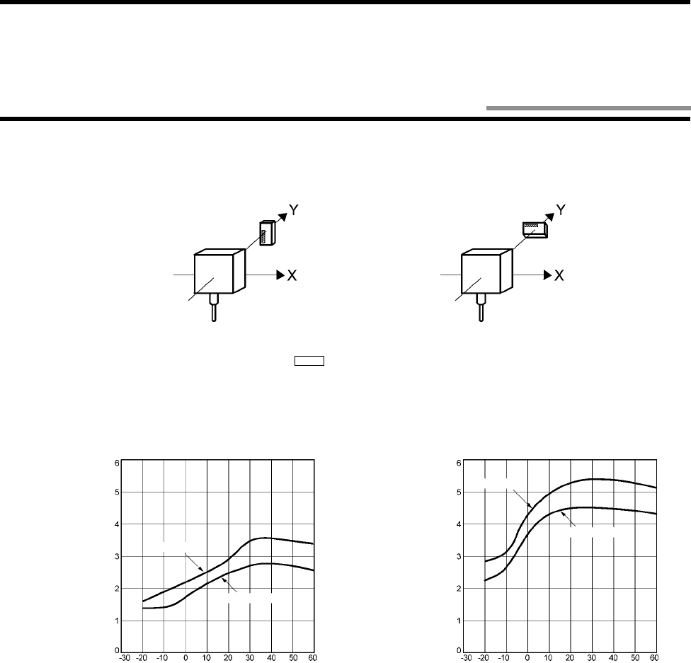
7-2
Influence of ambient temperature at tag rotating angle 0 degrees and 90 degrees is shown below.
Tag rotating angle 0 degrees Tag rotating angle 90 degrees
Antenna Tag Antenna Tag
2 m mode 5 m mode
Tag rotating angle 0 degrees
Tag rotating angle 90 degrees
Temperature (°C)
Distance
(m)
Tag rotating angle 0 degrees
Tag rotating angle 90 degrees
Temperature (°C)
Distance
(m)
* A hatched area on the tag shows a logo.
7-2 Influence of Ambient Temperature (Reference)
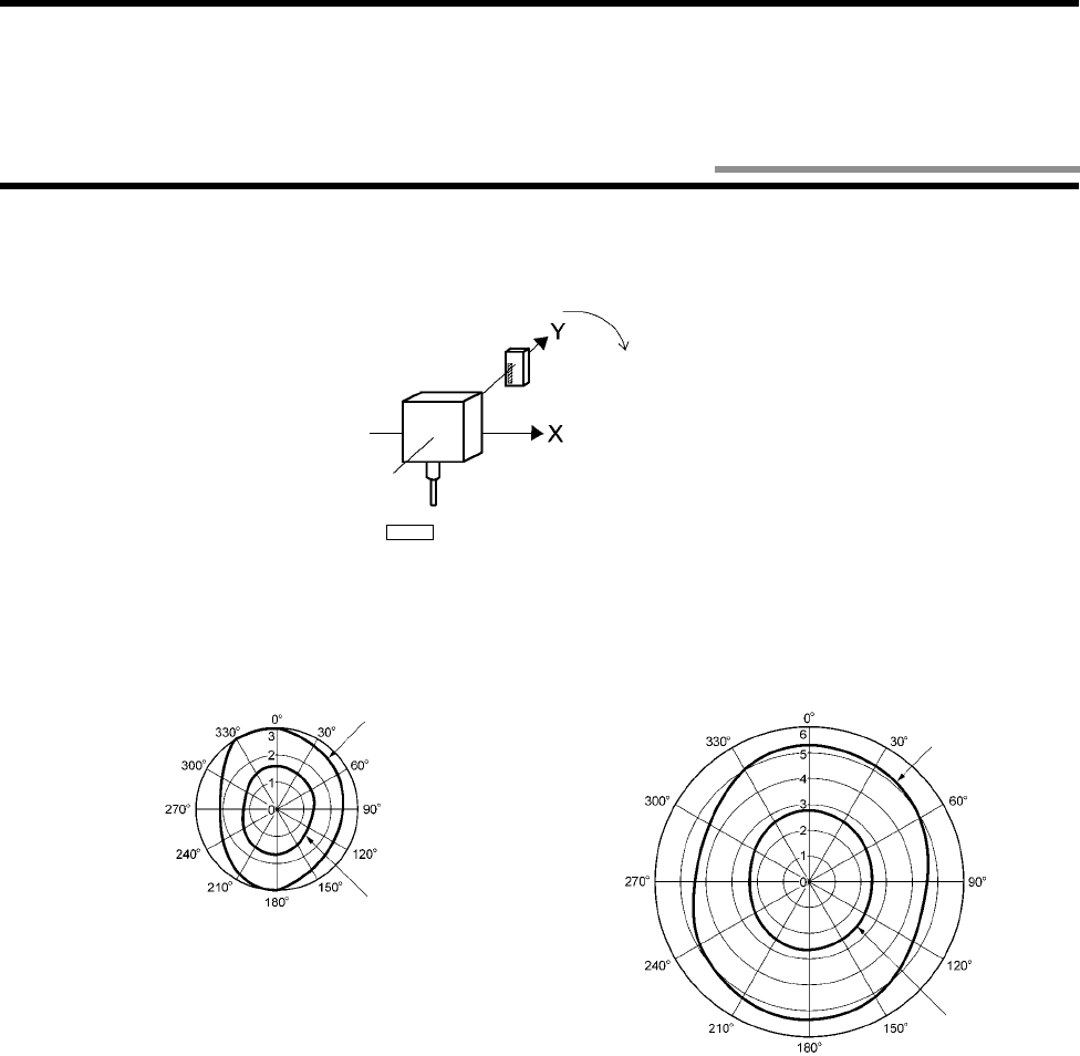
7-3
• Communication range fluctuating according to the variation of a tag angle to an antenna is shown below.
• Location of antenna and tag below shows the tag rotating angle 0 degrees.
Antenna Tag
2 m mode 5 m mode
Ambient temperature
+20°C
Tag rotating angle
Ambient temperature
-20°C
Ambient temperature
+20°C
Ambient temperature
-20°C
* A hatched area on the tag shows a logo.
7-3 Influence of Tag Rotation Angle (Reference)
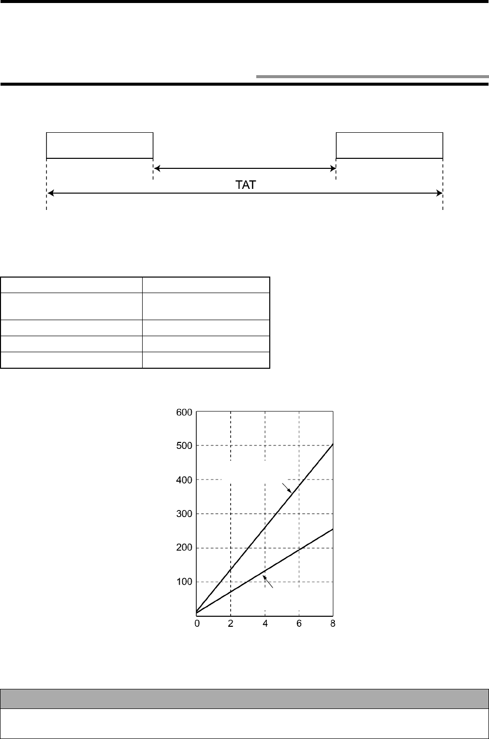
7-4
In the operation time, there are TAT (Turn Around Time) and communication time between the Read/Write antenna and ID tag.
(1) One tag
The communication designation is SU. N is the number of bytes. In case of Trigger, Auto and Repeat command.
Command Communication time (ms)
Read
Write (without verification read) t = 11 + 0.03 * N
Write (with verification read) t = 13 + 0.06 * N
ID code read t = 10
Communication test t = 1,100
Correct Usage
Communication speed (a maximum of 115.2 kbps) between a host device and antenna is faster than that between an
antenna and tag. So, if the tags move to the front of the antenna one after another, use the polling command.
Command Communication time Response
Communication time
(msec)
Write
(with verification read)
Read
Write (without verification read)
kbyte
7-4 Communication Time (Reference)
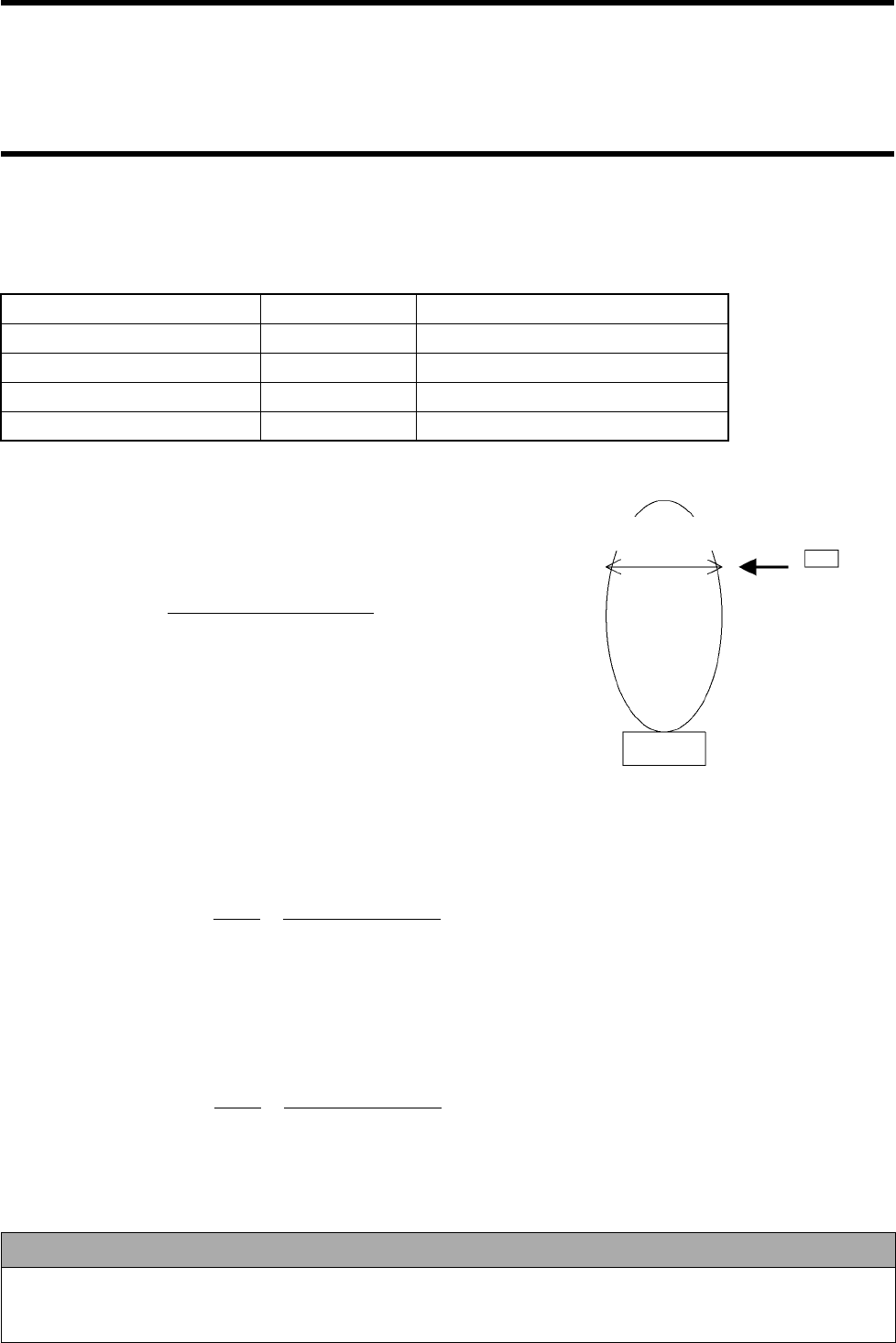
7-4 Communication Time (Reference)
7-5
(2) Multi (several tags)
The communication time of Multi command varies depending on the number of processed bytes, the number of tags and designation of
communication designation S/M/L. Average values are shown below.
(3) How to calculate maximum movement speed of tag
The maximum movement speed of tag moving at the front of antenna is calcu-
lated as follows:
Travel in communication area
Communication time
Example of calculation (1)
Calculate the movable speed of tag, based on the distance 1 m between the antenna and tag and 32-byte read.
If the distance is 2 m in the communication range 2m mode, the area width is 0.8 m.
The communication time of 32-byte read is 12 ms.
0.8 m 0.8 m
12 ms 0.012 x 1 / 60 (minutes)
Example of calculation (2)
Calculate the movable speed of tag, based on the distance 4 m between the antenna and tag and 256-byte read.
If the distance is 4 m in the communication range 5 m mode, the area width is 1.5 m.
The communication time of 256-byte read is 19 ms.
1.5 m 1.5 m
19 ms 0.019 x 1 / 60 (minutes)
Communication designation Number of tags Average communication time (ms)
U1 17
S Approximately 4 65
M Approximately 8 128
L Approximately 16 256
Correct Usage
The tag movement time above is a value of the best example. In an actual operation, taking into consideration periph-
eral objects and radio wave environment at the working site, design a system that a margin was removed from the calcu-
lated value and execute a test in the working site.
Travel
Tag
Antenna
Maximum movement speed =
Maximum movement speed = = 4 km per minute (= 240 km per hour)
=
Maximum movement speed = = 4.7 km per minute (= 280 km per hour)
=
7-6
• If several antennas are used, the communication may fail due to mutual interference. Keep specified installation space shown below.
Both radio wave channels are "5" (2450 MHz).
• Even if such installation space shown below cannot be kept, the space may be reduced by switching the radio wave channel. Refer to
Section 3-3.
•
••
•Installing antennas in parallel with each other
•
••
•Installing antennas facing each other
Communication range Space A
2 m mode 4.5 m or more
5 m mode 6 m or more
Communication range Space B
2 m mode 9 m or more
5 m mode 17 m or more
7-5 Mutual Interference Between Antennas (Reference)
7-7
• Due to radio wave interference caused by wireless LAN and cellular phone, the RFID system communication fails and the ID tag
battery power is consumed. (Refer to "Notes on Interference to Second-Generation Low-Power Data Communication System (Wire-
less LAN), Cellular Phone, etc." at the beginning of this manual.)
• Be sure to keep specified space from wireless LAN and cellular phone as shown below.
• If any trouble occurs, increase the space.
Note: Set the channel of wireless LAN to 1 (2400 MHz).
Prevention of RFID communication failure Prevention of ID tag battery power loss
Wireless LAN
Our WD30M
(Note) 3 m or more 2 m or more
Cellular phone
(800M, 1500 MHz) 1 m or more 50 cm or more
Personal handyphone
system (1900 MHz) 1 m or more 20 cm or more
Antenna
ID Tag
Space
Cellular phone
Wireless LAN
ID Tag
Space
Cellular phone
Wireless LAN
7-6 Space to Wireless LAN Cellular Phone (Reference)
7-8
• The maximum communication range can be achieved when the antenna face and tag face are in parallel with each other. If the
antenna and/or tag are inclined, the communication range becomes small. Install the tag paying attention to the tag angle.
• For the tag rotating angle 0 degrees and 90 degrees, deterioration characteristic of communication range depending on the tag angle
is shown below.
• Because of antenna position in the tag, communication range deterioration varies depending on the installation angle (whether "+" or
"-").
•
••
•Horizontal installation angle of tag
(1) Tag rotating angle 0 degrees
θ
θθ
θH (°
°°
°)Deterioration of communication range
2 m mode 5 m mode
+60 -54% -55%
+45 -38% -40%
+30 -23% -17%
+15 -12% -8%
00%0%
-15 0% -1%
-30 -4% -7%
-45 -11% -13%
-60 -26% -25%
Tag rotating angle 0 degrees Tag rotating angle 90 degrees
Antenna
Tag
Antenna
Tag
Upward
[Top View]
Antenna Model V690-HMG01 Tag Model V690-D8KR01
* A hatched area on the tag shows a logo.
7-7 Influence of Tag Installation Angle (Reference)
7-7 Influence of Tag Installation Angle (Reference)
7-9
(2) Tag rotating angle 90 degrees
•
••
•Vertical installation angle of tag
(1) Tag rotating angle 0 degrees
(2) Tag rotating angle 90 degrees
θ
θθ
θH (°
°°
°)Deterioration of communication range
2 m mode 5 m mode
+60 -40% -40%
+45 -23% -24%
+30 -14% -11%
+15 -6% -3%
00%0%
-15 -11% -10%
-30 -26% -23%
-45 -31% -35%
-60 -34% -37%
θ
θθ
θv (°
°°
°)Deterioration of communication range
2 m mode 5 m mode
+60 -41% -36%
+45 -26% -18%
+30 -10% -2%
+15 0% 0%
00%0%
-15 -16% -13%
-30 -23% -21%
-45 -30% -28%
-60 -42% -39%
θ
θθ
θH (°
°°
°)Deterioration of communication range
2 m mode 5 m mode
+60 -60% -67%
+45 -43% -50%
+30 -26% -27%
+15 -12% -14%
00%0%
-15 0% -3%
-30 -2% -6%
-45 -13% -14%
-60 -24% -27%
Antenna Model V690-HMG01 Tag Model V690-D8KR01
[Side View]
7-10
Deterioration characteristic of communication range depending on the distance between an antenna and tag back metal is shown below.
•
••
•Antenna
Influence of metal plate at the back of antenna on the
communication range is 1% or less.
*Metal plate 350 x 350 x 1 (thickness) mm,
aluminum, stainless steel.
•
••
•Tag
* Metal plate 120 x 120 x 1 (thickness) mm, aluminum,
stainless steel.
Distance between
back metal and tag
Communication
2 m mode 5 m mode
0 mm -10% -10%
5 mm -5% -5%
10 mm or more 0% 0%
Metal plate Antenna
Communica-
tion range Tag
Metal plate
Antenna
Communication range
Tag
Distance between back metal
and tag
7-8 Influence of Back Metal (Reference)

Appendix-1
Antenna
In this manual, this refers to the Read/Write antenna, a reader/writer which accesses an ID tag of the RFID system.
ARIB
Association of Radio Industries and Businesses, which issues the standards for radio equipment based on the Radio Law of Japan.
The first edition of Specified Low-Power Radio Station - Radio Equipment for Mobile Object Identification RCR STD-29 was
issued in 1992 and revised in July 2000 into Version 3.0
ASCII
American Standard Code for the Information Interchange. American standard character code. This is almost the same as JIS 7 unit
code for alphanumerical character, except that "¥" in JIS code is "\" in ASCII code.
AWG
Shows a wire size. As the AWG number becomes small, the wire size becomes large. For the cable of this product, cross-sectional
area of AWG22 is approximately 0.45 mm2 and that of AWG26 is approximately 0.18 mm2.
Circularly polarized wave
A wave that direction of electrical field (or magnetic field) is one way and not affected by time and place is referred to as "Linearly
polarized wave". On the other hand, a wave that direction of electrical field varies depending on time and place, i.e., the electrical
field rotates in the radio wave transmitting direction, is referred to as "Elliptically polarized wave". Among the elliptically polarized
waves, a wave that amplitude is constant is the circularly polarized wave.
Command
In this manual, this refers to an instruction from a host device to the Read/Write antenna.
Communication
In this manual, this refers to data communication between a host device and Read/Write antenna. Data communication between an
ID tag and Read/Write antenna is referred to as data exchange.
Data exchange
In this manual, this refers to data communication between an ID tag and Read/Write antenna.
Grounding Class D
Grounding method that grounding resistance is 100 Ω or less. This was formerly referred to "Grounding Class III".
Half-duplex communication
Although this is two-way data transmission, transmission can be performed only in one way at a time. In the full-duplex communi-
cation, the data transmission can be done in two ways simultaneously.
HEX
Hexadecimal number. A method to express a numerical value. The hexadecimal numbering system has a base of 16. The numbers
0 to 9 and characters A to F are used. The characters A to F correspond to the decimal numbers 10 to 15.
Host device
A device, such as PC, programmable controller (PLC), etc., to issue a command to the Read/Write antenna.
JIS8
Character code of JIS. There are 8 unit code (8 bits) and 7 unit code (7 bits). JIS8 unit code is for both of alphanumerical character
and Japanese Kana character.
m/s2
Unit of acceleration based on SI (International System of Units). The old unit is "G". 1G = 9.807 m/s2.
Microwave
This product uses 2450 MHz which is recognized as IMS band (for industrial, medical and scientific purpose) in the world.
N•m
Unit of torque based on SI (International System of Units). N is Newton. The old unit is "kgf•m". 1 kgf•m = 9.807 N•m.
Appendix
Appendix 1 Glossary

Appendix 1 Glossary
Appendix-2
Response
In this manual, this refers to a response returned by the Read/Write antenna after a host device issued an instruction to the Read/Write
antenna.
RFID
Radio Frequency Identification, i.e., automatic identification with radio system. Data about object is stored in the ID tag memory
and the data is read/written by a reader/writer without contacting.
RS-232C
Common physical interface standard of EIA (Electronics Industries Association). Communication speed 9600 bps can be achieved
in communication range 15 m.
RS-422A
Common physical interface standard of EIA (Electronics Industries Association). RS-422A is more excellent in noise resistance
than RS-232C and a maximum of 3000 m of communication range is available. Communication is performed through four wires.
Two wires are for sending and the others are for receiving.
RS-485
Common physical interface standard of EIA (Electronics Industries Association). The same line is used for both of sending and
receiving. So, communications can be made through two wires.
Second-generation low-power data communication system
Remarkably applicable wireless LAN which was legislated in 1999. A wide range of frequency band 2400 to 2483.5 MHz can be
used by the SS (Spread Spectrum) system and multiple channels are available. ARIB RCR STD-33 (1999) is the Standard.
Sleep, sleep state
The state that any communication to the Read/Write antenna is not performed. In this state, battery power is used only to back up
data in SRAM and the power consumption is 1/100 or less of the state that the ID tag operates or communicates. Therefore, to
extend the life of the battery of ID tag, we recommend you to put the ID tag in the sleep state whenever the ID tag does not work.
When the ID tag receives a radio wave from the Read/Write antenna, the ID tag quits the sleep state and works.
Specified low-power radio station
A radio station that the antenna power is 10 mW or less. A user is not required to apply a license for radio station. This product is
verified by Technical Regulation Conformity Certification of an official organization before shipment.
SRAM
Static RAM (Random Access Memory). Volatile memory. Data is backed up by battery.
Standby, standby state
The state that all the circuits in a tag are ready to operate after a command is executed. The battery power consumption is the same
as that at an operation such as communication. As a period of the standby state becomes short, the life of the battery can be extended.
Start-stop synchronization
Asynchronous data communication system which does not use synchronizing clock. Communication line is only one. Use it when
synchronizing clock cannot be sent.
Tag
In this manual, this refers to ID tag which is memory media accessed by the Read/Write antenna of the RFID system. As accurate
technical term, this is referred to as "Transponder". We call it "Tag" because "Transponder" is hard to say.
Terminating resistance
Put at both ends of communication line to prevent reflection in the communication line in RS-422A/RS-485.
Time slot
One of the systems that the Read/Write antenna accesses several ID tags. This system adopts the time slot. For example, if "M" (the
number of time slots = 16) is specified in the data exchange designation of a command, the antenna informs the ID tag that there are
16 time slots and every ID tag returns a response according to timing of any of 16 time slots. If responses of several ID tags collide
with each other, the time slots for those tags are rearranged. For "M", if the number of tags are approximately 8, probability of rear-
rangement is reduced and the total data exchange time is not prolonged so much.

Appendix 1 Glossary
Appendix-3
Wake instruction
A command for identification transmitted at every 100 msec when the Read/Write antenna transmitted a radio wave. The ID tag only
can identify it. When the ID tag receives the wake instruction, the ID tag continues an operation. If the ID tag cannot receive the
wake command, the ID tag enters the sleep state. The ID tag power-saving function described in Section 3-7 is achieved by utilizing
this function.

Appendix-4
Note 1: The code 01011100 (column 5, row 12) is " \ " in the ASCII character.
b8~b5 0000 1001
0010 0011 0100 0101 0110 0111 1000 1001 1010 1011 1100 1101 1110 1111
b4~b1 0 1 2 3 4 5 6 7 8 9 101112131415
0000 0 NUL TC
7
(DLE)
(SP)
0@P`p
Undefined
―タミ
0001 1
TC1(SOH)
DC
1
!1AQaq 。ア チ ム
0010 2 TC
2
(STX) DC
2
”2BRbr 「イツメ
0011 3 TC
3
(ETX) DC
3
#3CScs 」ウ テ モ
0100 4 TC
4
(EOT) DC
4
$4DTd t 、エ ト ヤ
0101 5
TC5(NEQ)
TC
8
(NAK) % 5 E U e u .オナユ
0110 6 TC
6
(ACK)
TC
9
(SYN)
&6FVf v ヲカニヨ
0111 7 BEL
TC10(ETB)
’7GWgw ァキヌラ
1000 8 FE
0
(BS) CAN ( 8 H X h x ィクネリ
1001 9 FE
1
(HT) EM ) 9 I Y i y ゥケノル
1010 10 FE
2
(LF) SUB * : J Z j z ェコハレ
1011 11 FE
3
(VT) ESC + ; K [ k { ォサヒロ
1100 12 FE
4
(FF) IS
4
(FS) , < L ¥l| ャシフワ
1101 13 FE
5
(CR) IS
3
(GS) - = M ] m } ュスヘン
1110 14 S0 IS
2
(RS) . > N ^ n ¯ ョセホ゛
1111 15 S1 IS
1
(US) / ? O _ o
DEL
ッソマ゜
Undefined
Undefined
Undefined
Undefined
Undefined
Appendix 2 JIS8 Unit Code List (ASCII Code List)
High order
digit
Low order
digit Column
Row
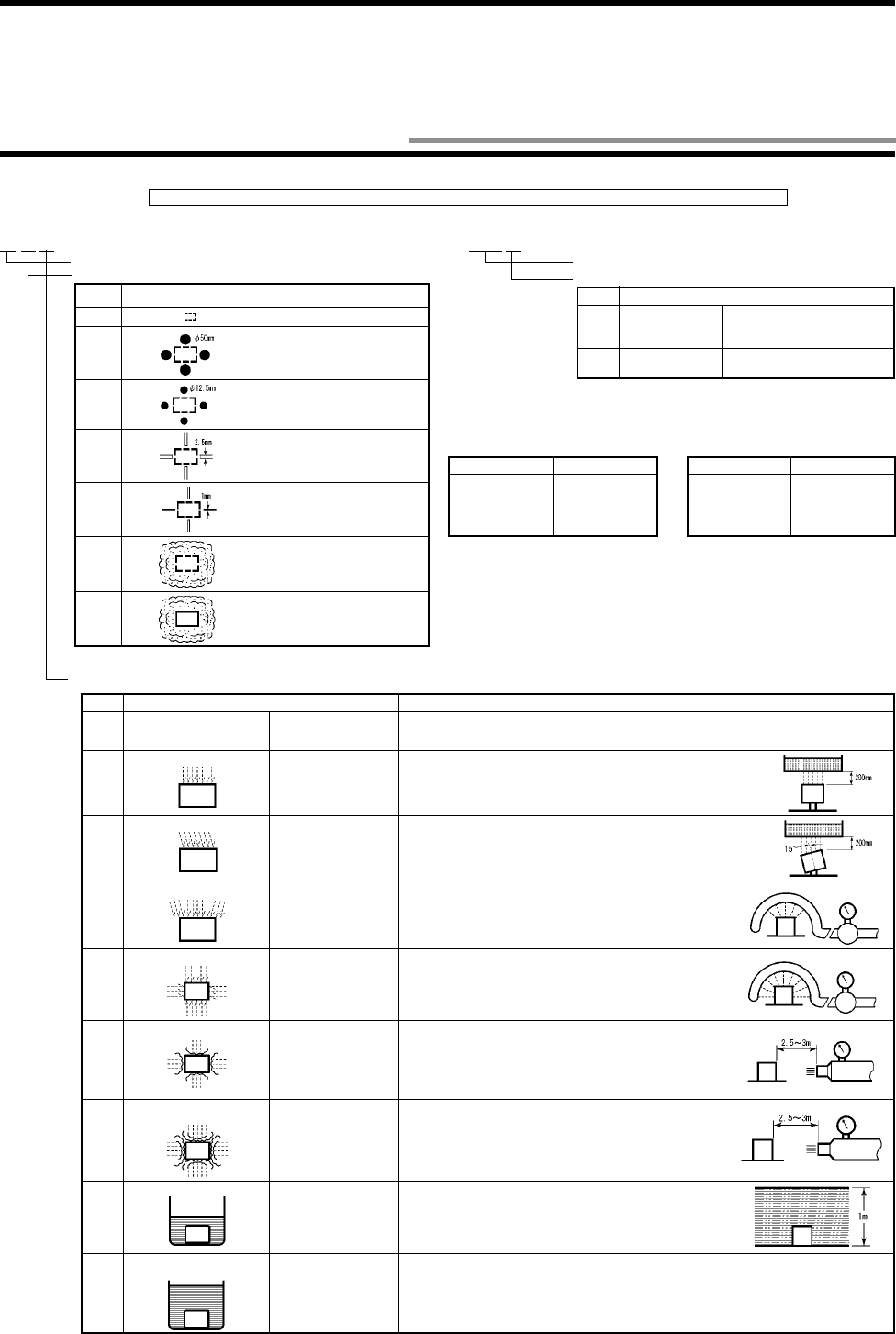
Appendix-5
NEMA (National Electrical Manufactures Association)
Table for conversion from NEMA enclosure into IEC60529. (Conversion from IEC60529 into
NEMA enclosure is unavailable.)
Note: Based on the NEMA Standards. The difference between NEMA enclosure classification and
IEC60529 is anticorrosion, rust prevention, moisture condensation on surface, etc.
Our test method
*1. In addition to the tests below, confirm that the proximity sensor IP67 repeats a heat shock cycle 5
times in cool water (0°C) for 1 hour and hot water (70°C) for 1 hour and that detected distance and
insulation resistance satisfy the performance.
*2. Working conditions of proximity sensor type E2F: Natural condition at 10 cm deep in water.
(1) Even if it is immersed in water of 2 atm for 1 hour, any water penetration must not be observed.
(2) Repeat the heat shock cycle above 20 times and confirm that detected distance and insulation
resistance satisfy the performance.
Appendix 3 Protective Structure
Protective property code (International Protection)
Protective classification for "1st Symbol" solid foreign material
Class Protection Level
0 No protection.
1 Solid foreign material 50 mm or
more in diameter (hand etc.) can-
not come in.
2 Solid foreign material 12.5 mm or
more in diameter (finger etc.) can-
not come in.
3 Solid foreign material 2.5 mm or
more in diameter (wire etc.) can-
not come in.
4 Solid foreign material 1 mm or
more in diameter (wire etc.) can-
not come in.
5 Dust, which interferes a normal
operation of device or spoils the
safety, cannot come in.
6 Any dust cannot come in.
Complies with the 1st and 2nd symbols of IEC60529.
Protective classification for oil penetration.
Note) There are four other classes: “h”, “c”, “d”, and “e”.
Class Protection Level
f Oil retaining type Not affected considerably by oil
drops or oil spray in any direc-
tion.
g Oil resistance type Any oil drop or oil spray in any
direction cannot come in.
•
••
•
Protective Structure
Note: IP-!!!
!!!!!!
!!! is classified by a test method below. Check sealing in working environment and operating conditions in advance.
♦
♦♦
♦
IEC
(International Electrotechnical Commission)
Standards
(IEC60529: 1989-11)
♦
♦♦
♦
JEM
(Japan Electrical Manufacturers’ Association)
Standards
(JEM1030: 1991)
IP-!
!!
! !
!!
!IP-!
!!
! !
!!
! !
!!
!
(January 1998)
NEMA250 IEC60529
1
2
3
3R
3S
IP10
IP11
IP54
IP14
IP54
NEMA250 IEC60529
4, 4X
5
6, 6P
12, 12K
13
IP56
IP52
IP67
IP52
IP54
Protective classification for "2nd Symbol" water penetration
Class Protection Level Test Method Overview (Test with fresh water)
0 No particular protection Any particular protection
is not taken to water
penetration.
No Test.
1
Protection against drop of water
Not to be affected by
water dropped vertically. Drop water for 10 minutes using a water drop tester.
2
Protection against drop of water
Not to be affected by
water dropped deviat-
ing 15° from a vertical
line.
Drop water to an object set inclined 15° for 10 minutes (2.5 minutes per
direction) using a water drop tester.
3
Protection against water spray
Not to be affected by
water spray deviating
within 60° from a vertical
line.
Spray water in an area within 60° to the right and left from a verti-
cal line for 10 minutes using a tester shown in this figure.
4
Protection against water splash
Not to be affected by
water splash from all the
directions.
Spray water from all the directions for 10 minutes using a tester
shown in this figure.
5
Protection against water jet flow
Not to be affected by
direct water jet flow from
all the directions.
Spray water from all the directions for 1 minute per surface area 1
m2, total 3 minutes or more using a tester shown in this figure.
6 Protection against extreme
water jet flow Not to be affected by
extreme direct water jet
flow from all the direc-
tions.
Spray water from all the directions for 1 minute per surface area 1
m2, total 3 minutes or more using a tester shown in this figure.
7
Protection against water soaking
Even if an object is
immersed in water of
specified pressure for a
specified time, any
water penetration must
not be observed.
Immerse an object at 1 m deep in water for 30 minutes (assuming
that device height is lower than 850 mm).
8 Protection against water
immersion An object must work
always in water. According to an agreement between a manufacturer and device user.
0.07 L/min per
spray nozzle
0.07 L/min per
spray nozzle
Water jet nozzle diameter: 6.3 mm
12.5 L/min
Water jet nozzle diameter: 12.5 mm
100 L/min
*1
*2
Appendix-6
♦
♦♦
♦Main unit and system components
Name/Shape Specifications Model
Antenna RS-232C/RS-422A interface
24 VDC power supply Model V690-HMG01
ID tag Memory capacity: 8 kbytes
Battery life: 5 years (25°C) Model V690-D8KR01
RS-422A/485 link unit RS-422A/485 interface
24 VDC power supply Model V690-L01
RS-232C connecting cable (for
IBM PC compatible machine) 2 m Model V690-A40
3 m Model V690-A41
5 m Model V690-A42
10 m Model V690-A43
15 m Model V690-A44
RS-422A/485 link unit connecting
cable 2 m Model V690-A50
3 m Model V690-A51
5 m Model V690-A52
10 m Model V690-A53
20 m Model V690-A54
30 m Model V690-A55
50 m Model V690-A56
Appendix 4 Order Format List

OMRON CORPORATION
Industrial Automation Company
Advanced Sensors Group
Sensing Devices and Components Division H.Q.
Shiokoji Horikawa, Shimogyo-ku,
Kyoto, 600-8530 Japan
Tel: (81)75-344-7069/Fax: (81)75-344-7107
Regional Headquarters
OMRON EUROPE B.V.
Wegalaan 67-69, NL-2132 JD Hoofddorp
The Netherlands
Tel: (31)2356-81-300/Fax: (31)2356-81-388
OMRON ELECTRONICS, INC.
1 East Commerce Drive, Schaumburg, IL 60173
U.S.A.
Tel: (1)847-843-7900/Fax: (1)847-843-8568
OMRON ASIA PACIFIC PTE. LTD.
83 Clemenceau Avenue,
#11-01, UE Square,
239920 Singapore
Tel: (65)835-3011/Fax: (65)835-2711
OMRON CHINA CO., LTD.
BEIJING OFFICE
Room 1028, Office Building,
Beijing Capital Times Square,
No. 88 West Chang’an Road,
Beijing, 100031 China
Tel: (86)10-8391-3005/Fax: (86)10-8391-3688

Authorized
Distributor:
Printed in JapanCat. No. Z149-E1-1 Note: Specifications subject to change without notice.