Omron Bu1002Sw Users Manual 01 Cover
BU3002SW to the manual 6fb5363c-f96a-4a1e-9a09-7b908532e505
2015-01-24
: Omron Omron-Bu1002Sw-Users-Manual-332572 omron-bu1002sw-users-manual-332572 omron pdf
Open the PDF directly: View PDF ![]() .
.
Page Count: 93
- BU1002SW/BU3002SW
- Introduction
- IMPORTANT SAFETY INSTRUCTION
- Safety precautions
- 1. Preparation
- 2. Installation and connection
- 3. Operation
- 4. UPS functions
- 5. Measuring the backup time
- 6. Maintenance and Inspection
- 7. Using the UPS monitoring software and contact signal
- 7-1 When using the included UPS monitoring software to perform auto shutdown
- 7-2 When performing auto-save functions using the UPS service in Windows Server 2003/XP/2000 + UPS service driver
- 7-3 When performing auto-save functions using the standard UPS service in Windows Server2003/XP/2000/NT
- 7-4 Contact signal
- 8. Using an SNMP/Web card
- 9. Extending the backup time
- 10. Troubleshooting
- References

•This manual provides important safety-related information. Thoroughly read and understand
this manual before installing and using the product.
•Keep this manual in a convenient location so that you can refer to it whenever necessary.
BU1002SW/BU3002SW
Uninterruptible Power Supply (UPS/200 to 240V specifications)
Instruction Manual
-
バッテリ
交換
バッテリ
増設
ブザー停止/テスト
電源出力
バイパス
運転
BU1002SW
-
バッテリ
交換
バッテリ
増設
ブザー停止/テスト
電源出力
バイパス
運転

Introduction
Features of this product
Thank you for purchasing Omron's Uninterruptible Power Supply (UPS).
●The UPS protects computers and other devices from power failures, voltage variations,
instantaneous voltage drops, and surge voltage such as that caused by lightning (a phenomenon
in which extraordinary high voltage occurs instantaneously).
●This unit is an uninterruptible power supply (UPS) with power supply output of 200 to 240V AC.
●Under normal conditions, it converts the commercial power to a direct current once, reconverts
it to a stable AC sine wave, and outputs it.
When a commercial power failure is detected, the unit switches to battery supply to provide
continuous sine wave output. This is especially suitable for use where power supply conditions
are poor (for example, when there are large variations in voltage).
●BU1002SW output capacity is 1000VA/700W, and BU3002SW output capacity is 3000VA/2100W.
©OMRON Corporation. 2006 All Rights Reserved.
Notes on the use of the Backup Power Supply
●This product is designed and manufactured for use for OA equipment such as personal
computers.
Do not use it when very high reliability and safety are required as listed below.
•Medical equipment that may cause death directly
•Applications that may cause injury (applications that directly affect the operation and con-
trol of planes, ships, railroads, elevators, and so on)
• Applications that are always subjected to vibration such as cars and ships
•Applications in which a failure of this product may cause significant damage or effect to
the society and public (important computer systems, main communication equipment,
public transportation systems, and so on)
• Equipment with the same level of importance
●For equipment that greatly affects the safety of people and maintaining public functions,
special considerations related to operation, maintenance, and management must be taken
such as duplicating the system and emergency power generation facilities.
●Observe the contents of this manual such as the use conditions and environments.
●When you want to use this product for an important system that requires very high reliability,
contact us; ______________________________
●Do not modify/alter this product.
Disclaimers
We are not liable for any damage or secondary damage resulting from the use of our product,
including malfunction and failure of equipment, connected devices, or software.
●Make sure to read the safety precautions before using the unit.
●In the event you transfer or sell this unit to a third party, please include all of the documentation
that came with this unit. This is to ensure that the unit is used in line with the conditions
described in the included documentation.
•This manual contains important safety-related information. Please read and understand
the contents of the manual before beginning operation.
If you discover any omissions or errors in the manual, please contact the shop of purchase.
●Windows is the registered trademark of Microsoft Corporation in the United States and/or other
countries.
●The names of other companies and products mentioned herein are the trademarks or registered
trademarks of their respective owners.
●Note on user registration Please fill out the required items on the included user registration
card and send it to our customer support center.
i

1
IMPORTANT SAFETY INSTRUCTION
1.SAVE THESE INSTRUCTIONS.
This manual contains important instructions for BU1002SW that should
be followed when using the UPS and batteries.
2.SYMBOL
This symbol indicates earth ground.
This symbol indicates turning on UPS.
This symbol indicates turning off UPS.
3.INTERNAL BATTERY
Internal battery voltage is 36V DC for BU1002SW and 72V DC for
BU3002SW.
4.TEMPERATURE RATING
The maximum ambient temperature of the UPS is 40°C.
5.ENVIRONMENT
The unit is intended for installation in a temperature controlled, indoor
area free of conductive contaminants.
2
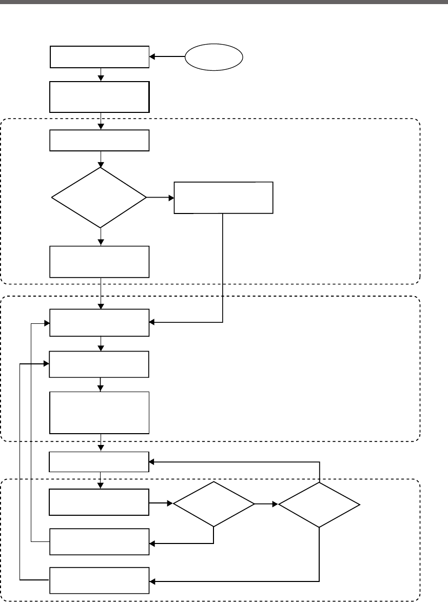
Procedure from installation to operation
Start
Installation/connection
Preparation for operation
Maintenance/
inspection
Yes
No
No
Yes Yes
No
Read “Safety precautions”
Page 4
Remove the product from the
package and check the contents
Page 12
Perform installation and
connection Page 21
Check the operation and
displays Pages 31
Charge the battery
Page 33
Measure the backup time
Page 33
Read “Using the UPS
monitoring software and
contact signal” Page 65
Operate Page 34
Deteriorated
battery? Fan stopped?
Perform maintenance
and inspection Page 53
Replace the battery
Page 54
Replace the fan
Page 62
Are you
using UPS monitoring
software or contact
signal?
Charge the battery again
Page 33
* Preparation for operation is
complete.

3
Table of Contents
■ Table of Contents ■
Introduction ......................................................................................................................................................... i
IMPORTANT SAFETY INSTRUCTION ............................................................................................................. 1
Safety precautions ............................................................................................................................................ 4
1. Preparation ............................................................................................................................. 12
1-1Unpacking the product ................................................................................................................................. 12
1-2Checking the contents ................................................................................................................................. 12
1-3Name of each part ....................................................................................................................................... 13
1-4Explanation of symbols used on unit ........................................................................................................... 16
2. Installation and connection ..................................................................................................... 17
2-1Precautions and notes on installation and connection ................................................................................. 17
2-2Installation and connection .......................................................................................................................... 21
2-3Connecting the equipment ........................................................................................................................... 24
2-4Checking the operation ................................................................................................................................ 31
2-5Charging the battery .................................................................................................................................... 33
2-6Measuring the initial value of backup time ................................................................................................... 33
2-7Recharging the battery ................................................................................................................................ 33
3. Operation ................................................................................................................................ 34
3-1Precautions and notes for operation ............................................................................................................ 34
3-2Start and stop procedures and basic operation ........................................................................................... 36
3-3Interpreting beeps and displays ................................................................................................................... 39
4. UPS functions ......................................................................................................................... 41
4-1Suspending a beep ...................................................................................................................................... 41
4-2Self-diagnosis test ....................................................................................................................................... 41
4-3Description of the auto battery test function ................................................................................................ 42
4-4Changing the setting of the functions .......................................................................................................... 42
5. Measuring the backup time .................................................................................................... 51
5-1How to measure backup time ...................................................................................................................... 51
5-2Estimated backup time ................................................................................................................................ 51
6. Maintenance and Inspection .................................................................................................. 53
6-1Checking the battery .................................................................................................................................... 53
6-2Replacing the battery ................................................................................................................................... 54
6-3Replacing the fan ......................................................................................................................................... 62
6-4Cleaning ....................................................................................................................................................... 64
7. Using the UPS monitoring software and contact signal .......................................................... 65
7-1When using the included UPS monitoring software to perform auto shutdown ........................................... 67
7-2 When performing auto-save functions using the UPS service in Windows Server 2003/XP/2000 + UPS ser-
vice driver .................................................................................................................................................... 70
7-3When performing auto-save functions using the standard UPS service in Windows Server 2003/XP/2000/NT
.................................................................................................................................................................... 71
7-4Contact signal .............................................................................................................................................. 77
8. Using an SNMP/Web card ...................................................................................................... 83
8-1Adding an SNMP/Web card ......................................................................................................................... 83
8-2 SNMP/Web card outline .............................................................................................................................. 84
9. Extending the backup time ...................................................................................................... 85
9-1 Connecting an additional battery unit .......................................................................................................... 85
10. Troubleshooting .................................................................................................................... 87
References .................................................................................................................................. 88
A. Specifications .............................................................................................................................................. 88
B. Dimensions .................................................................................................................................................. 89
C. Circuit block diagram .................................................................................................................................... 90
D. Related products .......................................................................................................................................... 90
4
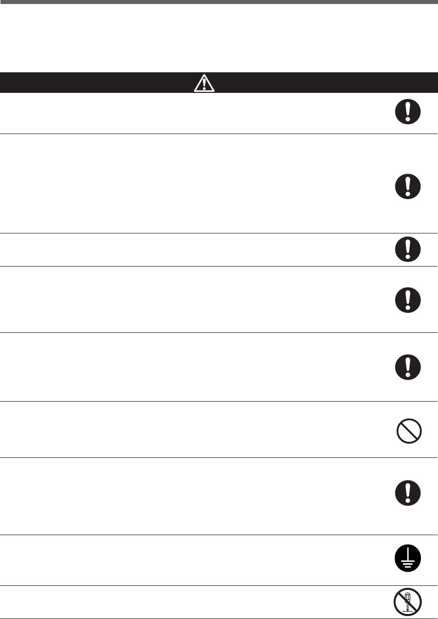
Safety precautions
:Indicates prohibition. For example, indicates that disassembly is prohibited.
:Indicates obligation. For example, indicates that grounding is necessary.
Misuse may cause death or serious injury.
Warning
Caution
Safety precautions
●The safety symbols and their meaning used in this manual are as follows:
* Property damage means damage to houses/household effects, livestock, and pets.
Note that events categorized as a caution required matter also may cause more serious results under certain
conditions.
Do not use this unit when very high reliability and safety are required as
listed below. This unit is designed and manufactured for use with OA
equipment such as personal computers.
●Medical equipment or system that may cause death directly.
●Applications that directly affect the safety of people (For example, the operation and control
of cars and elevators).
●Applications in which a failure of the unit may cause significant damage to the society and
public (For example, essential computer systems and main communication equipment.)
●Applications with the same level of importance.
Warning
Important information for safe operation is described.
Be sure to read it before installation and start of use.
Misuse may cause injury or property damage.
Two or more people should work together to carry, unpack and install the
BU3002SW.
●Because the unit is heavy, you may injure yourself or drop the unit, or it may fall over.
Carry the unit considering its weight and balance, and place it on a stable
and robust base.
●Dropping or toppling the unit may cause injury.
●Approximate weight of the unit:
15.5 kg (BU1002SW)
35 kg (BU3002SW)
●If you drop the unit, stop using it and have it inspected and repaired.
For repair, contact us; ____
Keep plastic package bags out of reach of children.
●Children may suffocate if they place their heads into plastic bags.
Make sure to connect the AC input plug of the unit into a wall outlet
(commercial power) with rated input voltage (200 to 240V AC).
●Connecting to a wall outlet (commercial power) of a different rated input voltage may result
in fire.
●The unit may fail.
Caution (for installation and connection)
5
Safety precautions
When an abnormality (unusual sound or smell) occurs, turn OFF the unit's
power switch and disconnect the AC input plug from the wall outlet.
Install the unit soon after the AC input plug is disconnected from the wall outlet.
●When performing maintenance on the connected devices, follow the above instructions to
ensure safety.
Do not connect devices such as dryers, some solenoid valves, etc. , which
have a half-wave rectifier that allows only half-cycle AC power to flow
through.
●Overcurrent may damage the UPS.
Connect the BU1002SW to a wall outlet (commercial power) with a capacity
of 7.4A or more, and connect the B3002SW to a wall outlet (commercial
power) with a capacity of 16A or more.
●Otherwise, the power cord may be heated.
●When equipment with the maximum output capacity is connected, a maximum current of
7.4A (BU1002SW) or 16A (BU3002SW) flows.
Provide secure grounding.
●
After checking the plug shape of the wall outlet, directly connect the AC input plug of the unit to it.
A failure or leak that occurs when the unit is not properly grounded may result in electric shock.
Do not disassemble, repair, or modify the unit.
●Doing so may cause an electric shock or a fire.
Do not install the unit in other than specified orientations.
●Dropping or toppling the unit may cause injury.
●If you install the unit in an orientation other than specified, the unit cannot be protected from a
battery fluid leakage.
Do not use the unit where the maximum temperature exceeds 40°C.
●The battery becomes weak rapidly, which may cause a fire.
●Doing so may cause a failure or malfunction of the unit.
Do not exceed the ranges specified for environmental conditions during
use/storage.
Do not install or store the unit in the places listed below.
●Do not store in places where the humidity is lower than 20% or higher than 90%.
●Do not use in places where the humidity is lower than 25% or higher than 85%.
●Do not use in closed spaces such as cabinets without clearance, or in places where flam-
mable or corrosive gases are present, places subject to vibration or shock, or outdoors.
●Installation or storing the unit in such a place may cause a fire.
Do not connect equipment that exceeds the output capacity of the unit.
You can use a 200V plug strip to connect additional devices, but do not
connect devices that exceed the current capacity of the plug strip.
●The current protection of the unit may operate, which may stop the output.
●The wiring of the plug strip heats up, which may cause a fire.
Do not pinch or tie the cable of the unit.
●
Doing so may cause the cable to be damaged or heated, which may cause an electric shock or a fire.
●If the cable is damaged, stop using the unit and have the cable repaired.
For repair, contact us; ____
Caution (for installation and connection)
6
Safety precautions
Caution (for installation and connection)
All of the included accessories are designed to be used exclusively with
the unit. Do not use the accessories with other devices.
●Doing so may compromise the safety of devices.
●This UPS utilizes voltages that may be hazardous. Do not attempt to disassemble the unit The
unit contains no user serviceable parts. Only factory service personnel may perform repairs.
●Connection to any other type of receptacle other than a two-pole,three-wire grounded recep-
tacle may result in shock hazard as well as violate local electical codes.
●Do not allow liquids or any foreign object to enter the UPS. DO not place beverages or any
other liquid-containing vessels on or near the unit.
●This unit intended for installation in a controlled environment (temperature controlled, indoor
area free of conductive contaminants). Avoid installing the UPS in locations where there is
standing or running water,or excessive humidity.
●Do not attach a power strip or surge suppressor to the UPS.
●Do not attach non-computer-related items,such as medical equipment,life-support
equipment,microwave ovens,or vacuum cleaners to UPS.
●With the installation of the equipment it should be prevented, that the sum of the leakage
current of the UPS and the connected consumer does not exceed 3.5mA.
Do not block the air vents on the unit. The BU1002SW has air vents on the
front, side and back, while the BU3002SW has air vents on the front and back.
●Doing so will cause the internal temperature to rise, which may cause the unit to fail and the
battery to deteriorate.
●Leave at least 5 cm of space between the vent and the wall.
Do not connect a standalone transformer such as a voltage transformer
or isolating transformer to the output side.
●Overcurrent may damage the UPS.
●There is no problem in connecting a transformer to the input side.
Do not connect devices that cannot be used with commercial power supply.
●When the unit’s power switch is turned ON and an error occurs with the connected device,
bypass operation is performed and commercial power supply is supplied as is to the con-
nected devices.
Do not connect devices with rated voltage of 200 to 240 VAC or higher.
●The rated output voltage of this device is 200 to 240 VAC.
●Overcurrent may damage the connected devices.
When in use, make sure the output terminal block cover is attached.
Do not turn ON the power switch when it is detached.
●Voltage is applied to the output terminal block when the power switch is ON, which can result
in electric shock.
For PLUGGABLE EQUIPMENT, the socket-outlet shall be installer near
the equipment and shall be easily accessible.
7
Safety precautions
Caution (for use)
Never touch the metal part of the input plug if it is disconnected while the
unit is operating.
●Doing so may result in electric shock.
●The leak current of this product itself is less than the value of the safety standard (leak current:
1 mA). However, because connected equipment causes the leak current to increase, you
must never touch the metal part of the input plug.
●When the unit is operating, voltage is generated in the metal parts of the input plug via ca-
pacitors in the internal circuit, regardless of the elapsed time.
Do not allow the unit to come in contact with water.
●Doing so may cause an electric shock or a fire.
●If the unit becomes wet, stop using it and have it inspected and/or repaired.
For repair, contact us:____________
When the battery is dead, replace it immediately or stop using the unit.
●Continuing the use of it may cause a fire.
Using a dry cloth, periodically wipe the dust from the AC input plug, power
supply output receptacles and output terminal block.
●Accumulated dust may cause a fire.
Do not use the unit in a closed place and do not cover the unit.
●Doing so may cause abnormal heating or a fire.
If you notice abnormal sound or smell, smoke, or leakage from the inside,
immediately turn off the power switch and disconnect the AC input plug
from a wall outlet (commercial power).
●Using the unit under such conditions may cause a fire.
●
If you notice such a condition, stop using the unit and contact us at _____ for inspection and repairs.
●Use the unit under the conditions in which you can immediately disconnect the AC input plug
from a wall outlet (commercial power) in the case of an abnormal event.
If fluid leaks from the unit, do not touch the fluid.
●Doing so may cause blindness or burns.
●
If the fluid contacts your eyes or skin, wash it out with lots of clean water and consult your doctor.
Do not place objects on the unit that are 25 kg or heavier, and do not drop
metal objects onto the unit.
●Doing so may cause distortion/damage to the case or a failure of the internal circuit, which
may cause a fire.
*The values in the table are the expected life under standard
use conditions and are not guaranteed.
Ambient temperature
20°C
30°C
Expected life
4 to 5 years
2 to 2.5 years
8
Safety precautions
Caution (for maintenance)
When maintaining the connected equipment, turn OFF the power switch
and disconnect the AC input plug.
●Even if you disconnect the AC input plug while the UPS is operating, the power output of this
unit does not stop and power is supplied from the outlet during a power failure.
Do not disassemble, repair, or modify the unit.
●Doing so may cause an electric shock or a fire.
If fluid leaks from the unit, do not touch the fluid.
●Doing so may cause blindness or burns.
●
If the fluid contacts your eyes or skin, wash it out with lots of clean water and consult your doctor.
Do not throw the unit into fire.
●The lead battery in the unit may explode, or leak dilute sulfuric acid.
Do not insert metal objects into the power supply output receptacle or terminal block of the UPS.
●Doing so may result in electric shock.
Do not insert metal objects into the battery connectors.
●Doing so may result in electric shock.
Caution (for battery replacement)
Perform replacement on a stable and flat place.
●Handle the battery carefully so that you do not drop it.
●Not doing so could cause injury or burns due to liquid (acid) leakage.
Use a specified battery for replacement.
●Not doing so may cause a fire.
●Product model: BP100XS (Replacement battery pack for BU1002SW)
BP150XS: Two required (Replacement battery pack for BU3002SW)
Do not replace the battery in a place where there is flammable gas.
●Spark may occur when connecting the battery, which may cause an explosion or fire.
If fluid (dilute sulfuric acid) leaks from the battery, do not touch the fluid.
●Doing so may cause blindness or burns.
●If it contacts your eyes or skin, wash it out with lots of clean water and consult your doctor.
Do not disassemble or modify the battery.
●Doing so could cause dilute sulfuric acid leak, which could cause blindness and burns.
Do not drop the battery and do not expose it to strong impact.
●Dilute sulfuric acid may leak.
Do not short the battery with metal objects.
●Doing so could cause an electric shock, fire or burn.
●Some electrical energy still remains inside the spent battery.
9
Safety precautions
Caution (for battery replacement)
Do not put the battery into fire and do not break it.
●The battery may explode or leak dilute sulfuric acid.
Do not use a new battery and an old battery at the same time.
●Dilute sulfuric acid may leak.
●A battery can present a risk of electrical shock and high short circuit current.The following
precautions should be observed when working on batteries:
1) Remove watches, rings, or other metal objects from the hands.
2) Use tools with insulated handles.
3) Wear rubber gloves and boots.
4) Do not lay tools or metal parts on top of batteries.
5) Disconnect charging source prior to connecting or disconnecting batteries terminals.
●Servicing of batteries should be performed or supervised by personnel knowledgeable of
batteries and the required precautions. Keep unauthorized personnel away from batteries.

10
Safety precautions
Notes
When moving the unit from a cold place to a warm place, leave it for several hours
before using it.
●If the unit is promptly turned ON after being moved to a warmer place, condensation may form inside the
unit and cause it to fail.
Charge the battery for at least 8 hours soon after purchasing the unit.
●If you do not use the unit for a long time after the purchase, the battery may deteriorate and the battery may
become unusable.
●To charge a battery, connect the AC input plug of the unit to a wall outlet (commercial power).
When storing the unit, charge the battery for at least 8 hours and turn OFF the power switch.
●Even if the unit is not used, the battery gradually discharges, and if it is left for a long time, it goes into an
over discharge state.
The backup time may become shorter or the battery may become unusable.
●We recommend keeping the temperature 25°C or less when storing the unit for long periods of time.
Connect the unit’s AC input plug to a wall outlet (commercial power) for at least 8 hours at the following
intervals:
- Every 6 months when storage temperature is 25°C or less
- Every 2 months when storage temperature is 40°C or less
●Turn off the power switch of the unit during storage.
Do not short the output lines of the unit to each other, and do not short the output
lines to the ground.
●The unit may fail.
Do not connect the AC input plug of the unit to its Power Supply Output Receptacle
during the Battery Mode.
●The unit may fail.
Do not connect a page printer (such as a laser printer) to the unit.
●The unit repeatedly and frequently switches between Commercial Power Mode and Battery Mode, which
may shorten the life of the battery.
●The page printer has a large peak current, so an excess of the connection capacity or a power failure due to
instantaneous voltage drop may be detected.
Check system operation beforehand if the unit is used in combination with a device
whose power supply frequency fluctuates widely, such as a personal electric
generator.
●The unit automatically recognizes the input power frequency when input power is supplied.If the unit is
connected when the input power frequency is not stable at the rated level, the unit may misidentify the
power supply frequency and may fail to operate normally. (If the unit is in operation, changing from commer-
cial power supply to another power supply source, such as generating equipment, will cause no problem.
Set the generator's frequency to the same level as that of the commercial power supply.)
Do not install or store the unit in a place exposed to direct sunlight.
●The rise of temperature may cause the built-in battery to deteriorate rapidly and become unusable.
Do not perform a withstand voltage test.
●The input circuit has a built-in surge absorption device. A withstand voltage test may break it.
●When performing an insulation resistance test, use the 400V DC range.
Before stopping the commercial power to the unit, turn OFF the power switch of the unit.
●The unit enters Battery Mode when commercial power is stopped. If you frequently use the unit in Battery
Mode, the battery life may be significantly shortened.
11
Safety precautions
Explanation
Usual operation
●You may either leave the power switch of the unit ON (operation status) or turn it OFF each time when
stopping the connected system. Choose whichever operation method is more convenient. We recommend
turning OFF the power switch when you do not use connected devices for a long time.
●
The battery can be charged once the AC input plug of the unit is connected to a wall outlet (commercial power).
Quitting Battery Mode
●If a power failure lasts for an extended period of time, the battery discharges and power output from the unit
stops. Shut down your computer after performing appropriate procedures (for example, saving data) while
the unit is still supplying power.
Rebooting
●If the battery discharges completely during a power failure, the unit stops. After recovery from the power
failure, the unit automatically restarts and supplies power. If you do not want to restart the connected
devices, turn OFF the power switch of either the unit or the connected devices.
Setting switch 2 can be used to select whether or not auto restart is performed. See Page 43
Scheduled operation using the UPS monitoring software
●When performing scheduled operation in which the UPS is stopped and a device such as a breaker is used
to stop the UPS at the same time that commercial power stops, specify a period of no more than 3 months for
the start of the next operation.
If you specify a period longer than 3 months, the internal timer is reset and the scheduled operation does not
start. Note that this period reduces to approximately half when the battery is dead. If a period of 3 months is
exceeded, you start operation by supplying commercial power and pressing the start switch. However, if
the battery is dead, you may not be able to start operation.
In this case, replace the battery according to the instructions in “6-2 Replacing the battery” on page 54.
Pb
Notes
Check the operation beforehand if the unit is used in any mode other than “Output
200V mode”.
●In Battery Mode, the maximum voltage (peak voltage) of output (rectangular wave) may be lower than the
maximum voltage in Commercial Power Mode. For this reason, some connected devices may fail to operate
normally.
If this unit is used with an inductive device such as a coil or motor, check the operation
beforehand.
●With some types of devices, the effect of inrush current may cause this unit to stop operating properly.
In the event you transfer or sell this unit to a third party, please include all of the
documentation that came with the unit. This is to ensure that the unit is used in line
with the conditions described in the included documentation.
●This manual contains important safety-related information. Please read and understand the
contents of the manual before beginning operation.
Take measures for handling unforeseen accidents, such as data backup and system
redundancy.
● The output may stop when there is a circuit failure in the UPS.
This unit uses lead acid batteries,
●Which are a valuable recyclable resource. Please recycle.
See also
12
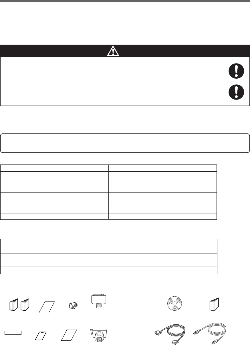
1. Preparation
BU1002SW BU3002SW
Instruction manual (Japanese and English versions)
1
Warranty 1
User registration card 1
Label (How to determine operating status) 1
Connector for remote ON/OFF 1
Te r minal block cover for output (with cable clamp) 1
Omron contact info label 1
BU1002SW BU3002SW
Quick installation guide 1
CD-ROM 1
Connection cable (RS-232C) 1
Connection cable (USB) 1
1-2 Checking the contents
Check whether all the package contents are included and there is no damage found on their appearance.
If you should notice defects or anything wrong, contact us; ____
(1) Accessories related to the main unit
(2) UPS monitoring software related items
Open the package box and take out the UPS and accessories.
Two or more people should work together to carry, unpack and install
the BU3002SW.
● Because the unit is heavy, you may injure yourself or drop the unit, or it may fall over.
The weight of the product is 15.5 kg (BU1002SW) , 35 kg (BU3002SW).
Unpack/transport this product considering this weight.
●Dropping may cause injury.
Caution
1. Preparation
1-1 Unpacking the product
Warranty
User registration
card
Label (How to
determine
operating status)
Quick installation
guide
CD-ROM
Connection cable(USB)
(Approx. 2.2 m)
<Accessories related to main unit> <UPS monitoring software>
Instruction manual
(Japanese/English
edition)
Connector for
remote
ON/OFF
OMRON contact
info label Connection cable(RS-232C)
(Approx. 2.2 m)
Te r minal block cover
for BU1002SW (with
cable clamp)
Te r minal block cover
for BU3002SW (with
cable clamp)
13
1. Preparation
1-3 Name of each part
This section describes the name of each part of the UPS.
For information on the function of each part, refer to "2. Installation and connection" on page 17 and "3. Opera-
tion" on page 34 that provides the details.
Front view
[ Enlarged view of the display panel ]
BU1002SW
-
バッテリ
交換
バッテリ
増設
ブザー停止/テスト
電源出力
バイパス
運転
A. Status indicator digital display
B. Power switch
C. Beep stop/test switch
D. Battery addition lamp
E. Battery replacement lamp
F. Power supply output lamp
G. Bypass operation lamp
(The input power supply is output as is.)
H. Setting switch cover
I. Connection capacity/battery level meter
-
バッテリ
交換
バッテリ
増設
ブザー停止/テスト
電源出力
バイパス
運転
A
I
B
C
H
GF E D
<BU1002SW>
-
バッテリ
交換
バッテリ
増設
ブザー停止/テスト
電源出力
バイパス
運転
<BU3002SW>
<Display panel>
(Carrying handle)
(Air vent)
14
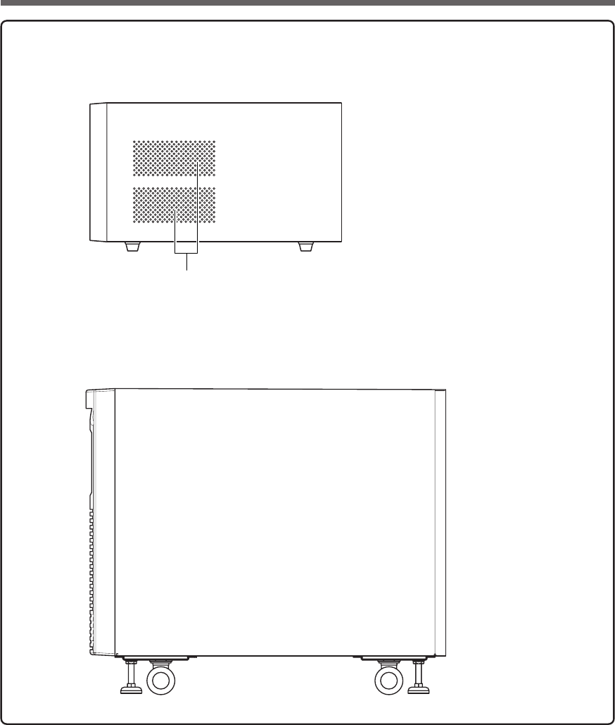
1. Preparation
Side view
Air inlet
Rear side
Front side
Rear side
Front side
<BU1002SW>
<BU3002SW>
15
1. Preparation
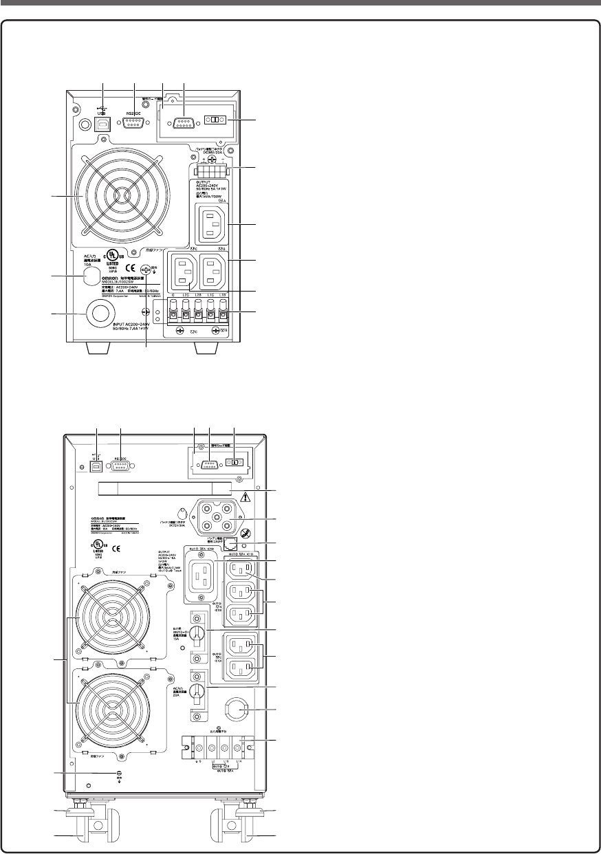
Rear view
A. USB connector
B. RS-232C connector
C. Contact signal card
D. Contact signal connector
E. Remote ON/OFF connector
F. Additional battery connector
G. Power supply output receptacle A (IEC60320 C13)
H. Power supply output receptacle B (IEC60320 C13)
I. Power supply output receptacle C (IEC60320 C13)
J. Terminal block for output
K. Grounding terminal
L. AC input cable
M. AC input overcurrent protection
N. Cooling fan
<BU1002SW>
A
K
M
L
N
B C D
F
E
G
I
H
J
MAX
A B C D
F
E
G
H
K
J
I
L
M
N
O
P
Q
R
Q
R
S
T
See installation Instructions
before connecting to the supply.
Not For Current Interrupting.
Refer to the instruction manual for the
tightening torque.
Use Copper Conductor
Only.
INPUT AC200–240V
50/60Hz 16A 1ø3W
<BU3002SW>
A. USB connector
B. RS-232C connector
C. Contact signal card
D. Contact signal connector
E. Remote ON/OFF connector
F. Handle
G. Additional battery connector
H. Additional battery signal connector
I. Power supply output receptacle A (IEC60320 C19)
J. Power supply output receptacle A (IEC60320 C13)
K. Power supply output receptacle B (IEC60320 C13)
L. Overcurrent protection switch for output 15A
M. Power supply output receptacle C (IEC60320 C13)
N. AC input overcurrent protection switch 20A
O. AC input cable
P. Terminal block for output
Q. Fixed stand
R. Casters
S. Grounding terminal
T. Cooling fan

16
1. Preparation
1-4 Explanation of symbols used on unit
Symbol Description
Start the UPS.
Stop the UPS.
Suspend a beep.
UPS output power enabled, supplied by operating on line mode, battery mode.
UPS operating on battery mode.
Additional battery unit connected to the UPS. (For BU100XS only.)
Error occurred with UPS.
Batteries at end of useful life, necessary to replace the batteries.
17
2. Installation and connection
2. Installation and connection
2-1
Precautions and notes on installation and connection
Two or more people should work together to carry, unpack and install the
BU3002SW.
●Because the unit is heavy, you may injure yourself or drop the unit, or it may fall over.
Carry the unit considering its weight and balance, and place it on a stable
and robust base.
●Dropping or toppling the unit may cause injury.
●Approximate weight of the unit:
15.5 kg (BU1002SW)
35 kg (BU3002SW)
●If you drop the unit, stop using it and have it inspected and repaired.
For repair, contact us; ____
Keep plastic package bags out of reach of children.
●Children may suffocate if they place their heads into plastic bags.
Make sure to connect the AC input plug of the unit into a wall outlet
(commercial power) with rated input voltage (200 to 240V AC).
●Connecting to a wall outlet (commercial power) of a different rated input voltage may result
in fire.
●The unit may fail.
When an abnormality (unusual sound or smell) occurs, turn OFF the unit's
power switch and disconnect the AC input plug from the wall outlet.
Install the unit soon after the AC input plug is disconnected from the wall outlet.
●When performing maintenance on the connected devices, follow the above instructions to
ensure safety.
Do not connect devices such as dryers, some solenoid valves, etc. , which
have a half-wave rectifier that allows only half-cycle AC power to flow
through.
●Overcurrent may damage the UPS.
Connect the BU1002SW to a wall outlet (commercial power) with a capacity
of 7.4A or more, and connect the B3002SW to a wall outlet (commercial
power) with a capacity of 16A or more.
●Otherwise, the power cord may be heated.
●When equipment with the maximum output capacity is connected, a maximum current of 7.4A
(BU1002SW) or 16A (BU3002SW) flows.
Provide secure grounding.
●After checking the plug shape of the wall outlet, directly connect the AC input plug of the unit
to it. A failure or leak that occurs when the unit is not properly grounded may result in electric
shock.
Do not disassemble, repair, or modify the unit.
●Doing so may cause an electric shock or a fire.
Caution (for installation and connection)
18
2. Installation and connection
Caution (for installation and connection)
Do not install the unit in other than specified orientations.
●Dropping or toppling the unit may cause injury.
●If you install the unit in an orientation other than specified, the unit cannot be protected from a
battery fluid leakage.
Do not use the unit where the maximum temperature exceeds 40°C.
●The battery becomes weak rapidly, which may cause a fire.
●Doing so may cause a failure or malfunction of the unit.
Do not exceed the ranges specified for environmental conditions during
use/storage.
Do not install or store the unit in the places listed below.
●Do not store in places where the humidity is lower than 20% or higher than 90%.
●Do not use in places where the humidity is lower than 25% or higher than 85%.
●Do not use in closed spaces such as cabinets without clearance, or in places where flam-
mable or corrosive gases are present, places subject to vibration or shock, or outdoors.
●Installation or storing the unit in such a place may cause a fire.
Do not connect equipment that exceeds the output capacity of the unit.
You can use a 200V plug strip to connect additional devices, but do not
connect devices that exceed the current capacity of the plug strip.
●The current protection of the unit may operate, which may stop the output.
●The wiring of the plug strip heats up, which may cause a fire.
Do not pinch or tie the cable of the unit.
●
Doing so may cause the cable to be damaged or heated, which may cause an electric shock or a fire.
●If the cable is damaged, stop using the unit and have the cable repaired.
For repair, contact us; ____
All of the included accessories are designed to be used exclusively with
the unit. Do not use the accessories with other devices.
●Doing so may compromise the safety of devices.
●This UPS utilizes voltages that may be hazardous. Do not attempt to disassemble the unit The
unit contains no user serviceable parts.Only factory service personnel may perform repairs.
●Connection to any other type of receptacle other than a two-pole,three-wire grounded recep-
tacle may result in shock hazard as well as violate local electical codes.
●Do not allow liquids or any foreign object to enter the UPS.DO not place beverages or any
other liquid-containing vessels on or near the unit.
●This unit intended for installation in a controlled environment (temperature controlled, indoor
area free of conductive contaminants).Avoid installing the UPS in locations where there is
standing or running water,or excessive humidity.
●Do not attach a power strip or surge suppressor to the UPS.
●Do not attach non-computer-related items,such as medical equipment,life-support
equipment,microwave ovens,or vacuum cleaners to UPS.
●With the installation of the equipment it should be prevented, that the sum of the leakage
current of the UPS and the connected consumer does not exceed 3.5mA.
19
2. Installation and connection
Caution (for installation and connection)
Do not block the air vents on the unit. The BU1002SW has air vents on the
front, side and back, while the BU3002SW has air vents on the front and back.
●Doing so will cause the internal temperature to rise, which may cause the unit to fail and the
battery to deteriorate.
●Leave at least 5 cm of space between the vent and the wall.
Do not connect a standalone transformer such as a voltage transformer
or isolating transformer to the output side.
●Overcurrent may damage the UPS.
●There is no problem in connecting a transformer to the input side.
Do not connect devices that cannot be used with commercial power supply.
●When the unit’s power switch is turned ON and an error occurs with the connected device,
bypass operation is performed and commercial power supply is supplied as is to the con-
nected devices.
Do not connect devices with rated voltage of 200 to 240 VAC or higher.
●The rated output voltage of this device is 200 to 240 VAC.
●Overcurrent may damage the connected devices.
When in use, make sure the output terminal block cover is attached.
Do not turn ON the power switch when it is detached.
●Voltage is applied to the output terminal block when the power switch is ON, which can result
in electric shock.
For PLUGGABLE EQUIPMENT, the socket-outlet shall be installer near
the equipment and shall be easily accessible.
Notes
When moving the unit from a cold place to a warm place, leave it for several hours
before using it.
●If the unit is promptly turned ON after being moved to a warmer place, condensation may form inside the
unit and cause it to fail.
Charge the battery for at least 8 hours soon after purchasing the unit.
●If you do not use the unit for a long time after the purchase, the battery may deteriorate and the battery may
become unusable.
●To charge a battery, connect the AC input plug of the unit to a wall outlet (commercial power).
When storing the unit, charge the battery for at least 8 hours and turn OFF the power switch.
●Even if the unit is not used, the battery gradually discharges, and if it is left for a long time, it goes into an
over discharge state.
The backup time may become shorter or the battery may become unusable.
●We recommend keeping the temperature 25°C or less when storing the unit for long periods of time.
Connect the unit’s AC input plug to a wall outlet (commercial power) for at least 8 hours at the following
intervals:
- Every 6 months when storage temperature is 25°C or less
- Every 2 months when storage temperature is 40°C or less
●Turn off the power switch of the unit during storage.

20
2. Installation and connection
Notes
Do not short the output lines of the unit to each other, and do not short the output
lines to the ground.
●The unit may fail.
Do not connect the AC input plug of the unit to its Power Supply Output Receptacle
during the Battery Mode.
●The unit may fail.
Do not connect a page printer (such as a laser printer) to the unit.
●The unit repeatedly and frequently switches between Commercial Power Mode and Battery Mode, which
may shorten the life of the battery.
●The page printer has a large peak current, so an excess of the connection capacity or a power failure due
to instantaneous voltage drop may be detected.
Check system operation beforehand if the unit is used in combination with a device
whose power supply frequency fluctuates widely, such as a personal electric
generator.
●The unit automatically recognizes the input power frequency when input power is supplied.If the unit is
connected when the input power frequency is not stable at the rated level, the unit may misidentify the
power supply frequency and may fail to operate normally. (If the unit is in operation, changing from commer-
cial power supply to another power supply source, such as generating equipment, will cause no problem.
Set the generator's frequency to the same level as that of the commercial power supply.)
Do not install or store the unit in a place exposed to direct sunlight.
●The rise of temperature may cause the built-in battery to deteriorate rapidly and become unusable.
Do not perform a withstand voltage test.
●The input circuit has a built-in surge absorption device. A withstand voltage test may break it.
●When performing an insulation resistance test, use the 400VDC range.
Before stopping the commercial power to the unit, turn OFF the power switch of the
unit.
●The unit enters Battery Mode when commercial power is stopped. If you frequently use the unit in Battery
Mode, the battery life may be significantly shortened.
Check the operation beforehand if the unit is used in any mode other than “Output
200V mode”.
●In Battery Mode, the maximum voltage (peak voltage) of output (rectangular wave) may be lower than the
maximum voltage in Commercial Power Mode. For this reason, some connected devices may fail to oper-
ate normally.
If this unit is used with an inductive device such as a coil or motor, check the operation
beforehand.
●With some types of devices, the effect of inrush current may cause this unit to stop operating properly.
21
2. Installation and connection
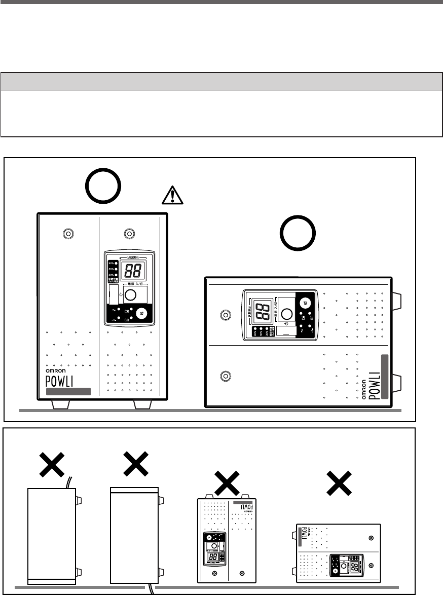
2-2 Installation and connection
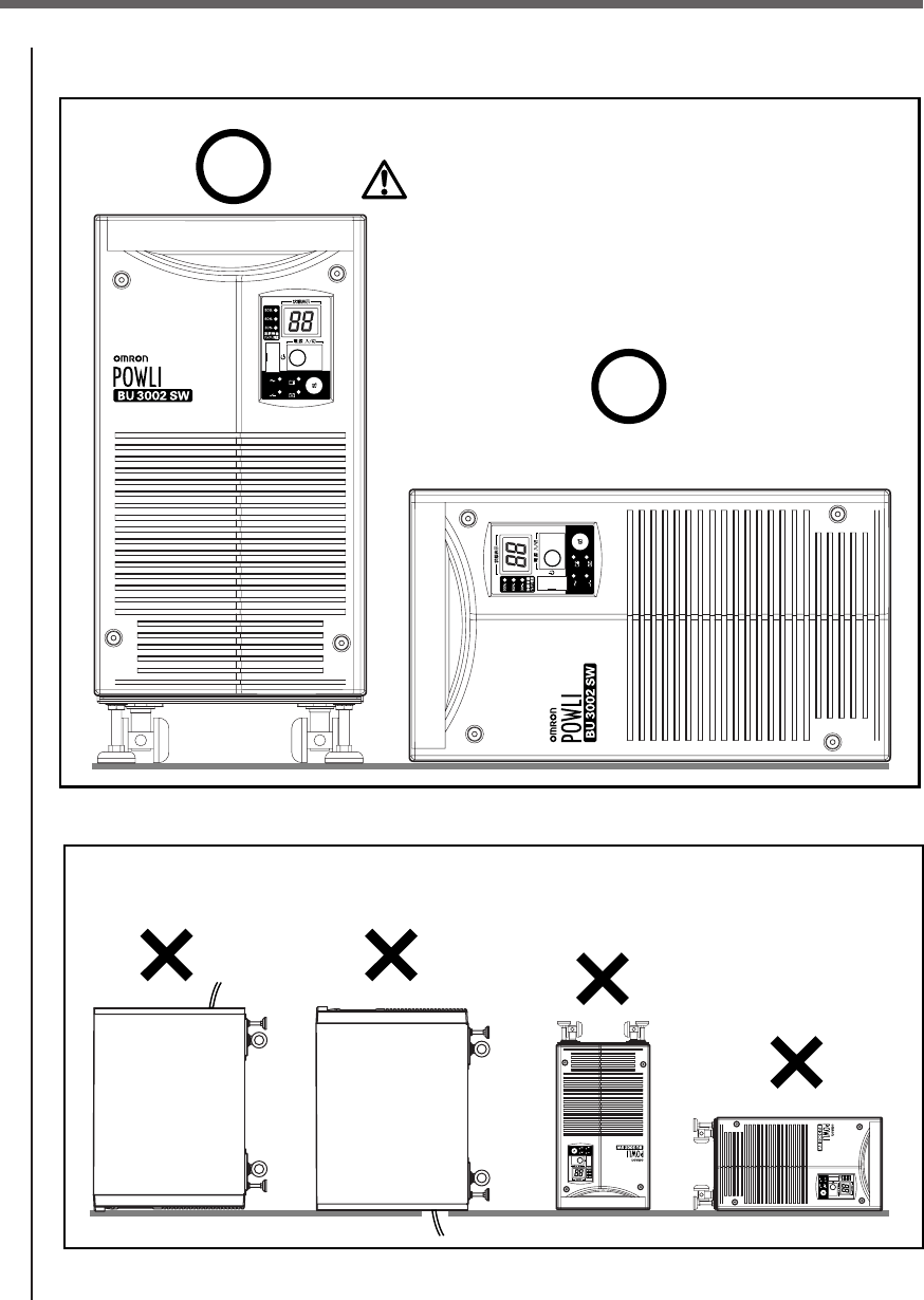
This section describes how to install the UPS. Do not use this unit in any position other than the “correct
positions” indicated in the illustration below.
Note
Before installing this device, make a record of the serial number of this device.
The serial number is required when contacting us about the device.
The serial number is written in the label on the unit's top side.
-
バッテリ
交換
バッテリ
増設
ブザー停止/テスト
電源出力
バイパス
運転
-
バッテリ
交換
バッテリ
増設
ブザー停止/テスト
電源出力
バイパス
運転
BU1002SW
BU1002SW
Incorrect Positions
-
バッテリ
交換
バッテリ
増設
ブザー停止/テスト
電源出力
バイパス
運転
-
バッテリ
交換
バッテリ
増設
ブザー停止/テスト
電源出力
バイパス
運転
BU1002SW
BU1002SW
Correct Positions
Be careful not to get your fingers caught
when arranging the unit.
(Air vents are facing upward)
< BU1002SW >
*The feet can also be anchored to the floor with screws if you use BUP100S mounting brackets (sold separately).
Refer to the BUP100S instruction manual for more details.
22
2. Installation and connection
< BU3002SW >
-
バッテリ
交換
バッテリ
増設
ブザー停止/テスト
電源出力
バイパス
運転
-
バッテリ
交換
バッテリ
増設
ブザー停止/テスト
電源出力
バイパス
運転
Incorrect Positions
-
バッテリ
交換
バッテリ
増設
ブザー停止/テスト
電源出力
バイパス
運転
-
バッテリ
交換
バッテリ
増設
ブザー停止/テスト
電源出力
バイパス
運転
Correct Positions
Be careful not to get your fingers caught
when arranging the unit.
Caster at the bottom may be removed
when sitting horizontally.
(Display panel are facing upward)
23
2. Installation and connection
<Installing the BU3002SW vertically>
● Stabilize the casters
● How to stabilize the fixed stand
Use a monkey wrench or spanner to loosen the fixed
stand nuts.
Unscrew the feet of the fixed stand until they reach
the floor.
Continue to unscrew the feet of the fixed stand until
the casters no longer touch the floor.
Once the fixed stand feet are firmly on the floor, turn
the nuts counter-clockwise to tighten them and lock
the feet in place.
*The feet can be anchored to the floor with screws if you use BUP300S mounting brackets (sold sepa-
rately).
Refer to the BUP300S instruction manual for more details.
<Installing the BU3002SW horizontally>
● How to remove the bottom casters
Install the BU3002SW so that the control panel is facing upward.
Loosen the screws in the 6 locations shown in the diagram below.
Remove caster mounting plate.
Casters locked
Casters unlocked
* BUP300S mounting brackets (sold separately) can be used for easy mounting on an EIA/JIS 19-inch rack.
Refer to the BUP300S instruction manual for more details.
24
2. Installation and connection
2-3 Connecting the equipment
< Example of
connection 1 >
< Example of
connection 2 >
Connected
device (1)
Connected
device (2)
Connected
device (1)
Connected
device (2)
BU1002SW
BU3002SW
To t he terminal
block for output
To t he terminal
block for output
To power supply
output receptacle
PC
To power supply
output receptacle
PC
●Group control of power supply output
This function can be used with the UPS monitoring software included with the UPS.
The output receptacles of the BU1002SW are separated into 3 groups: A, B, and C.
1. Power supply output group A
Output begins at the same time as startup.
2. Power supply output group B, C
•The output start times for power supply output group B and C are independent of power supply
output group A, so they can be delayed or set to precede the output stop time.
•The output start/stop time control funtion is available when using the included “PowerAct Pro” UPS
monitoring software, “UPS Power Manager” or “SNMP/Web card”.
•
Output ON/OFF can be controlled with the included UPS monitoring software while the
BU1002SW
is
operating.
•The delay settings and ON/OFF control described here can be performed independently for power
supply output group B and power supply output group C.
This function can be used to set the startup order of servers, peripheral devices, etc.
The output receptacles can also be forcibly turned ON/OFF remotely.
Do not connect devices with rated voltage of 200 to 240 VAC or higher.
●The rated output voltage of this device is 200 to 240 VAC.
●Overcurrent may damage the connected devices.
When in use, make sure the output terminal block cover is attached.
Do not turn ON the power switch when it is detached.
●Voltage is applied to the output terminal block when the power switch is ON, which can
result in electric shock.
Caution
25
2. Installation and connection
Plug of connected device
Connect it directly.
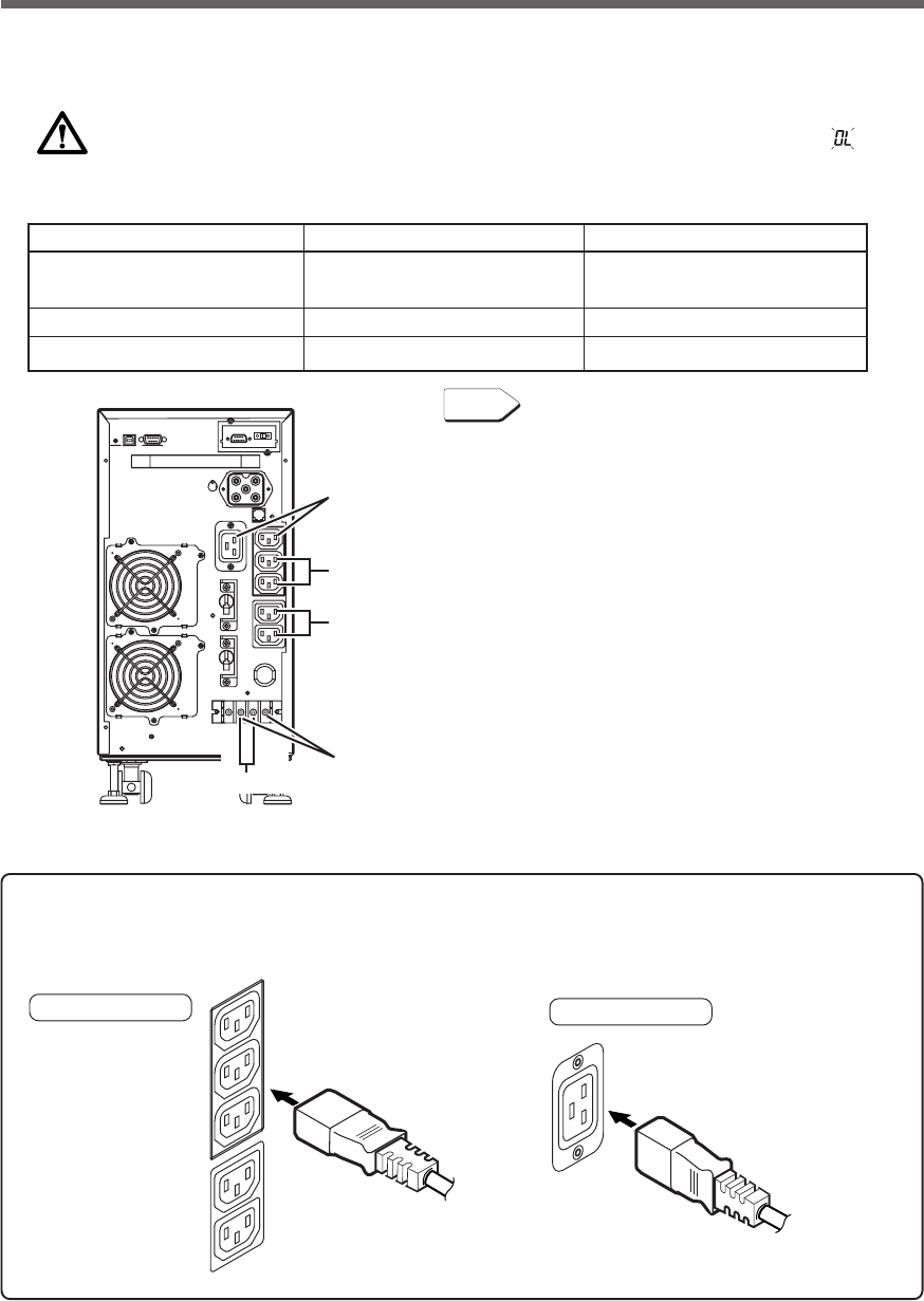
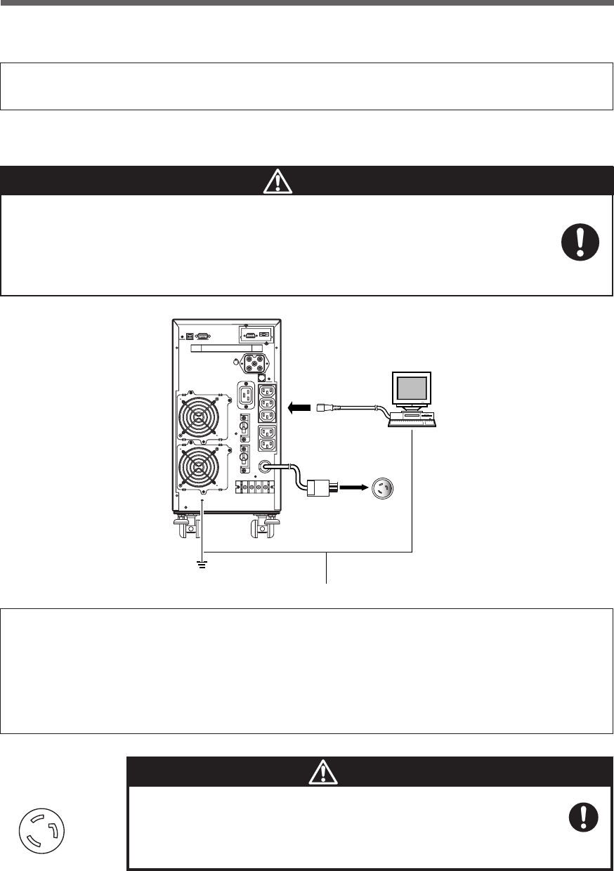
• Procedure for connection to power supply output receptacle (IEC60320 C13)
2-3-1 Connecting a device to the power supply output (BU1002SW)
(1) Connect devices that require backup to the unit's power supply output receptacle or output terminal block.
Group A
Group B
Group B
Group C
Group C
Make sure that the total capacity of the devices connected to the output receptacle does not
exceed the output rated capacity of the BU1002SW. If the overload indication ( ) is dis-
played, reduce the number of connected devices.
BU1002SW (Rated value of output capacity: Max. 1kVA/700W)
“Power supply output” group Output receptacle Output terminal block
Group A C13: 1 (Rated capacity: 15A) –
Group B C13: 1 (Rated capacity: 15A) 1 line (Rated capacity: 20A)
Group C C13: 1 (Rated capacity: 15A) 1 line (Rated capacity: 20A)
Power supply output group A
Output ON
Time setting
Time setting Time setting
Time setting
Output OFF
Power supply output group B
Power supply output group C
Group control of power supply output
See Page 24
See also
26
2. Installation and connection
CB
L1BL1CL2BL2CG
● Procedure for connection to BU1002SW output terminal block
When in use, make sure the output terminal block cover is attached.
Do not turn ON the power switch when it is detached.
●Voltage is applied to the output terminal block when the power switch is ON, which can
result in electric shock.
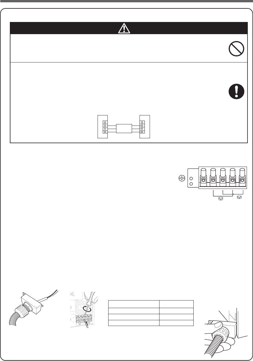
When connecting a device to the output terminal block, make sure to
include an emergency stop switch (ESD) between them.
●In the event of an accident, the power supply to the device can be stopped by pressing
the emergency stop switch.
●A disconnect switch shall be provided by others for ac output terminal block circuit.
●To reduce the risk of fire, connect only to a circuit provided with branch circuit overcurrent
protection for 15 amperes rating in accordance with the National Electric Code, ANSI/
NFPA 70.
Caution
(1) Remove the terminal block cover on the lower right side of the
unit’s rear panel.
(2) Connect the units that need to be backed up. Two types of connec-
tions can be made.
1) To turn ON/OFF at the same timing as that of output receptacle
B:
L1B terminal: Connect the line
L2B terminal: Connect the neutral line
2) To turn ON/OFF at the same timing as that of output receptacle
C:
L1C terminal: Connect the line
L2C terminal: Connect the neutral line
Run the wires to be connected through the hole in the included terminal block cover (with cable
clamp and cable guard tube). (See Figure 1.)
If you have trouble running the wire through the hole, loosen the cable clamp dial by turning it
counter-clockwise.
Connect the ground wire to the G terminal.
Use a flat head screwdriver to loosen the terminal block screws, insert the wire, and then retighten
the screws. (See Figure 2.) Refer to Table 1 for wire sizes.
ESD
UPS Load
Figure 1
emergency stop
switch (ESD)
Table 1
Connectable wire size 1.0 to 2.5 mm2
Amount of stripped wire 5.5mm
Tightening torque 0.9Nm(8 lb-in)
Recommended cable size 2mm2 (AWG14)
(3) Insert the tab on the right side of the terminal block cover (with cable clamp)
into the unit’s body, and fasten the previously removed screws to the two loca-
tions on the left side of the cover.
Tighten the cable clamp dial to stabilize the wire. (See Figure 2.)
<BU1002SW>
Figure 2
Figure 3
27
2. Installation and connection
<BU1002SW>
200 to 240 VAC
3P receptacle
Grounding terminal
PC
Connect the ground wire to the Grounding terminal.
(2) When using the included UPS monitoring software and the Windows standard UPS service, use a connec-
tion cable to connect the unit to the PC.
See also "7. Using the UPS monitoring software and Contact Signal" on page 65
* If you do not use the UPS monitoring software and Contact Signal, this step is not required.
Make sure to connect the AC input plug of the unit into a wall outlet
(commercial power) with rated input voltage (200 to 240V AC).
●Connecting to a wall outlet (commercial power) of a different rated input voltage may result
in fire.
●The unit may fail.
Caution
(3) When the installation and connection is complete, connect the AC Input Plug of the UPS to a wall outlet
(commercial power).
●The UPS has been charged prior to shipment. However, the backup time becomes shorter when
using it for the first time due to spontaneous discharge.
We recommend charging the UPS before using it.
When the AC input plug is connected to a wall outlet (commercial power), the battery automatically
starts charging, taking up to 8 hours to complete (24 hours when an additional battery unit is
connected).
●You can perform "2-4 Checking the operation" on page 31 also before charging the battery.
Input plug (L6-15P)
(Front view)
When one wire is used to ground the AC input power
supply, make sure to use this unit's N terminal (phase)
side as the ground.
●A misconnection may result in malfunction.
Caution
28
2. Installation and connection
• Procedure for connection
to power supply output receptacle (IEC60320
C13)
2-3-2 Connecting a device to the power supply output (BU3002SW)
(1) Connect devices that require backup to the unit's power supply output receptacle or output terminal block.
Make sure that the total capacity of the devices connected to the output receptacle does not
exceed the output rated capacity of the BU3002SW. If the overload indication ( ) is dis-
played, reduce the number of connected devices.
BU3002SW (Rated value of output capacity: Max. 3kVA/2100W)
“Power supply output” group Output receptacle Output terminal block
Group A C19: 1 (Rated capacity: 20A) 1 line (Rated capacity: 20A)
C13: 1 (Rated capacity: 15A)
Group B C13: 2 (Rated capacity: 15A) 1 line (Rated capacity: 20A)
Group C C13: 2 (Rated capacity: 15A) –
Group B
Group B
Group A
Group C
Group A
• Procedure for connection
to power supply output receptacle (IEC60320
C19)
Connect it directly. Connect it directly.
Plug of connected device
Plug of connected device
Group control of power supply output
See Page 24
See also
29
2. Installation and connection
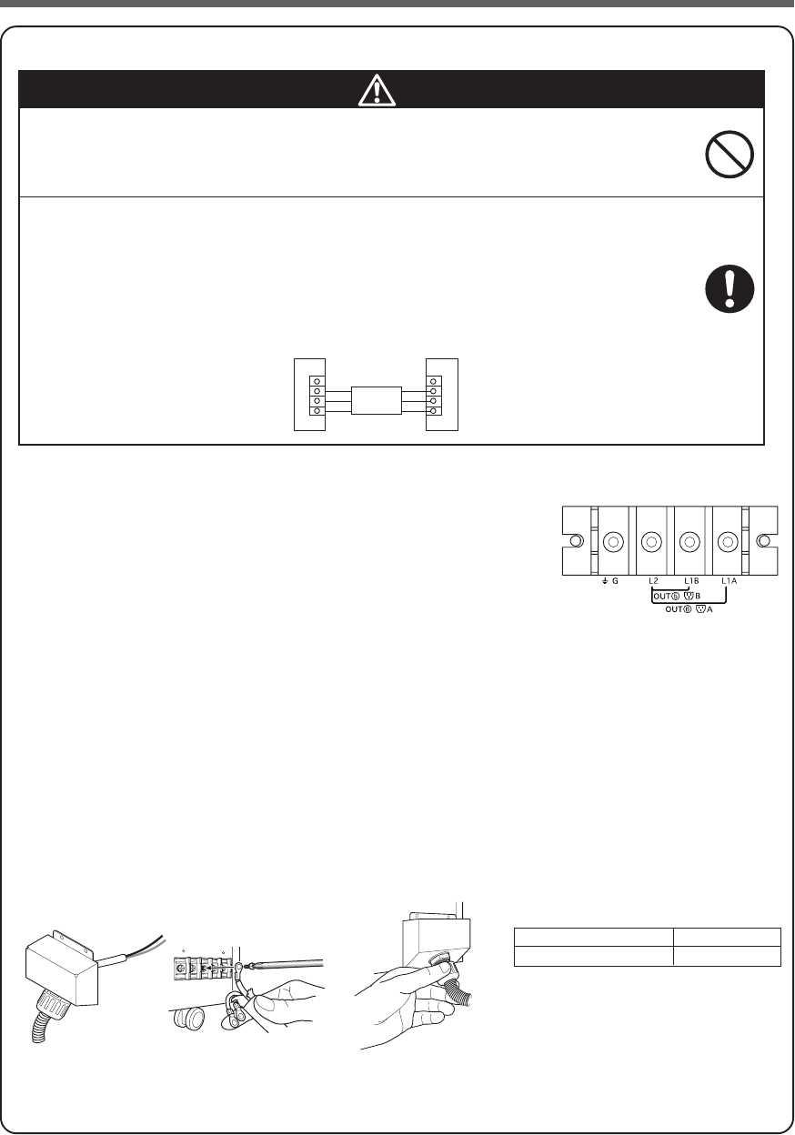
● Procedure for connection to BU3002SW output terminal block
Caution
(1) Remove the terminal block cover on the lower right side of the unit’s
rear panel.
(2) Remove the transparent cover.
(3) Connect the units that need to be backed up.
Two-line connection can be made.
1) To turn ON/OFF at the same timing as that of output receptacle A:
L1A terminal: Connect the line
L2 terminal: Connect the neutral line
2) To turn ON/OFF at the same timing as that of output receptacle B:
L1B terminal: Connect the line
L2 terminal: Connect the neutral line
(4) Run the wires to be connected through the hole in the included terminal block cover (with cable
clamp and cable guard tube).
(See Figure 1.)
Connect the ground wire to the G terminal.
Use a Phillips screwdriver to remove the terminal block screws, and connect the wire attached to the
round pressure terminal. (See Figure 2.)
Refer to Table 1 for round pressure terminal sizes.
Figure 1 Table 1
Diameter of screw M5 Screw
Tightening torque 2 Nm(17.7 lb-in)
(5) Cover the terminal block with terminal block cover (with cable clamp) , and fasten the previously
removed screws to the two locations on the upper side of the cover.
Tighten the cable clamp dial to stabilize the wire.(See Figure 3.)
<BU3002SW>
Figure 2
Figure 3
When in use, make sure the output terminal block cover is attached.
Do not turn ON the power switch when it is detached.
●Voltage is applied to the output terminal block when the power switch is ON, which can
result in electric shock.
When connecting a device to the output terminal block, make sure to
include an emergency stop switch (ESD) between them.
●In the event of an accident, the power supply to the device can be stopped by pressing
the emergency stop switch.
●A disconnect switch shall be provided by others for ac output terminal block circuit.
●To reduce the risk of fire, connect only to a circuit provided with branch circuit overcurrent
protection for 20 amperes rating in accordance with the National Electric Code, ANSI/
NFPA 70.
Caution
ESD
UPS Load
emergency stop
switch (ESD)
30
2. Installation and connection
<BU3002SW>
(2) When using the included UPS monitoring software and the Windows standard UPS service, use a connec-
tion cable to connect the unit to the PC.
See also "7. Using the UPS monitoring software and Contact Signal" on page 65
* If you do not use the UPS monitoring software and Contact Signal, this step is not required.
Make sure to connect the AC input plug of the unit into a wall outlet
(commercial power) with rated input voltage (200 to 240V AC).
●Connecting to a wall outlet (commercial power) of a different rated input voltage may result
in fire.
●The unit may fail.
Caution
(3) When the installation and connection is complete, connect the AC Input Plug of the UPS to a wall outlet
(commercial power).
●The UPS has been charged prior to shipment. However, the backup time becomes shorter when
using it for the first time due to spontaneous discharge.
We recommend charging the UPS before using it.
When the AC input plug is connected to a wall outlet (commercial power), the battery automatically
starts charging, taking up to 8 hours to complete (24 hours when an additional battery unit is
connected).
●You can perform "2-4 Checking the operation" on page 31 also before charging the battery.
Input plug (L6-20P)
(Front view)
When one wire is used to ground the AC input power
supply, make sure to use this unit's N terminal (phase)
side as the ground.
●A misconnection may result in malfunction.
Caution
200 to 240 VAC
3P receptacle
Grounding terminal
PC
Connect the ground wire to the Grounding terminal.
E
N
L
31
2. Installation and connection
2-4 Checking the operation
After you finish connecting devices to the unit, make sure the backup function operates properly.
Check that the Battery Mode is performed normally according to the following procedure.
(This operation check simulates a power failure by disconnecting the AC input plug from a wall outlet.)
(1) Turn ON the unit's power switch.
The beeper sounds and the current settings are displayed on the LED.
After 5 secounds, the self-diagnostic test is performed in Battery Mode for approximately 10 seconds.
When the self-diagnostic test finishes successfully, switching to AC output from commercial power is per-
formed and the the display below is shown.
(If the battery voltage is low, the self-diagnostic test is not performed and the operation starts immediately,
using output from commercial power.)
(2) Bring all the connected devices into operation.
(Including devices connected to the AC outlet of your PC.)
Operate the devices in a way in which abrupt power stop
does not damage the connected devices, data, etc.
(3) Under this condition, check the the unit's LED display and beep sound.
Are they in the same status as shown below?
If the same as the one shown above:
➜The operation is normal. Proceed to (4).
If not the same as the one shown above:
➜The operation is abnormal. One of the cases described in "4. Dis-
play and beeps when there is an equipment failure" of "3-3 Inter-
preting a beep and displays" on page 39 must apply.
Take necessary measures and then proceed to (4).
(4) Disconnect the AC input plug of this unit from a wall outlet (commercial power).
The UPS enters Battery Mode.
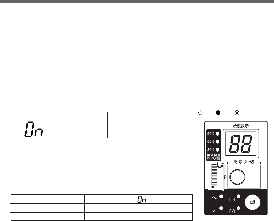
Status indicator Description
Power switch “ON”
Operating normally
Status indicator
Beep
Power supply output receptacles
None
Outputs power (connected devices are powered)
-
バッテリ
交換
バッテリ
増設
ブザー停止/テスト
電源出力
バイパス
運転
ON DIP
1 2 5678
3 4
ON OFF ON, OFF, or blinking
depending on status
32
2. Installation and connection
(5) In Battery Mode, check the unit's LED display and beep sound.
Does the status indicator appear as one of those shown below?
If not the same as one of those shown above:
➜Operation is abnormal. Check the status of lamps and beep and
turn OFF the Power Switch.
•If the display is one of those shown in “4. Displays and beeps
when there is an equipment failure” in “3-3 Interpreting beeps
and displays” on page 39, take the necessary measures and
then go back to (1) on page 31.
•If no Battery Mode is performed and the UPS and the devices
connected to the UPS stop, this may be attributed to an insuffi-
cient battery charge.
After connecting the AC input plug to a wall outlet (commercial
power) and waiting at least 8 hours for the battery to charge (24
hours when an additional battery unit is connected), go back to
(4) on page 31.
•If the problem persists after checking the 2 points above, con-
tact us; ____
See also
Setting switch 1 can be used to turn the beeper ON/OFF. ➛ Page 43
(6) Connect the AC input plug to a wall outlet (commercial power) again.
The status indicator returns to its normal state and the beeping sound stops.
(The status is as shown below.)
Checking the operation is now complete.
Installation and connection is now complete.
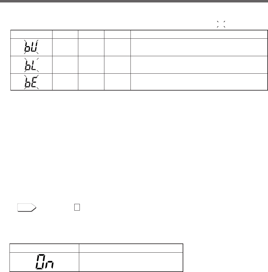
( indicates blinking)
Status indicator Description
Backup is operating due to power failure or AC input error.
Output will stop if Battery Mode continues.
(Same as above.)
Battery level is low, so output will stop soon.
Battery is dead, so output stopped. (This is displayed only
for a few seconds.)
Status indicator Description
Power switch “ON”
Operating normally
Beep
Intermittent
4-second
intervals
Intermittent
1-second
intervals
None
Output
ON
ON
OFF
Charging
OFF
Discharging
OFF
Discharging
OFF
Discharging
33
2. Installation and connection
2-5 Charging the battery
When you connect the AC input plug of this unit to a wall outlet (commercial power), the battery charg-
ing automatically starts regardless of whether the power switch is ON or OFF, and it is fully charged
within 8 hours. (When an additional battery unit is connected, the charging time is 24 hours.)
●This unit has been charged prior to shipment. However, the backup time becomes shorter when using it for
the first time due to spontaneous discharge. We recommend charging this unit before using it.
●If you do not perform the initial backup time measurement described below in “2-6 Measuring the initial
value of backup time”, proceed to “3. Operation”. → Page 34
2-6 Measuring the initial value of backup time
●When you measure the backup time initial value of the unit in your environment, this value can be used as
a guide when checking the battery and deciding the UPS monitoring software setting values.
See also
"5. Measuring the backup time" → Page 51
2-7 Recharging the battery
The battery is discharged completely when the backup time is measured, so you need to recharge it before
using the UPS.
●You can use connected devices while recharging the battery, but the backup time when a power failure
occurs is shorter until the battery is fully charged.
(If a power failure occurs immediately after the start of charging, backup stops immediately.)
See also
Charge the battery as described in "2-5 Charging the battery."
Preparation for starting operation is now complete.
34
3. Operation
3. Operation
3-1 Precautions and notes for operation
Never touch the metal part of the input plug if it is disconnected while the
unit is operating.
●Doing so may result in electric shock.
●The leak current of this product itself is less than the value of the safety standard (leak current:
1 mA). However, because connected equipment causes the leak current to increase, you
must never touch the metal part of the input plug.
●When the unit is operating, voltage is generated in the metal parts of the input plug via
capacitors in the internal circuit, regardless of the elapsed time.
Do not allow the unit to come in contact with water.
●Doing so may cause an electric shock or a fire.
●If the unit becomes wet, stop using it and have it inspected and/or repaired.
For repair, contact us:____________
When the battery is dead, replace it immediately or stop using the unit.
●Continuing the use of it may cause a fire.
Using a dry cloth, periodically wipe the dust from the AC input plug, power
supply output receptacles and output terminal block.
●Accumulated dust may cause a fire.
Do not use the unit in a closed place and do not cover the unit.
●Doing so may cause abnormal heating or a fire.
If you notice abnormal sound or smell, smoke, or leakage from the inside,
immediately turn OFF the power switch and disconnect the AC input plug
from a wall outlet (commercial power).
●Using the unit under such conditions may cause a fire.
●
If you notice such a condition, stop using the unit and contact us at _____ for inspection and repairs.
●Use the unit under the conditions in which you can immediately disconnect the AC input plug
from a wall outlet (commercial power) in the case of an abnormal event.
If fluid leaks from the unit, do not touch the fluid.
●Doing so may cause blindness or burns.
●
If the fluid contacts your eyes or skin, wash it out with lots of clean water and consult your doctor.
Do not place objects on the unit that are 25 kg or heavier, and do not drop
metal objects onto the unit.
●Doing so may cause distortion/damage to the case or a failure of the internal circuit, which
may cause a fire.
Caution (for use)
*The values in the table are the expected life under standard
use conditions and are not guaranteed.
Ambient temperature
20°C
30°C
Expected life
4 to 5 years
2 to 2.5 years
35
3. Operation
Explanation
Usual operation
●You may either leave the power switch of the unit ON (operation status) or turn it OFF each time when
stopping the connected system. Choose whichever operation method is more convenient. We recommend
turning OFF the power switch when you do not use connected devices for a long time.
●The battery can be charged once the AC input plug of the unit is connected to a wall outlet (commercial
power).
Quitting Battery Mode
●If a power failure lasts for an extended period of time, the battery discharges and power output from the unit
stops. Shut down your computer after performing appropriate procedures (for example, saving data) while
the unit is still supplying power.
Rebooting
●If the battery discharges completely during a power failure, the unit stops. After recovery from the power
failure, the unit automatically restarts and supplies power. If you do not want to restart the connected de-
vices, turn OFF the power switch of either the unit or the connected devices.
See also
Setting switch 2 can be used to select whether or not auto restart is performed. See Page 43
Scheduled operation using the UPS monitoring software
●When performing scheduled operation in which the UPS is stopped and a device such as a breaker is used
to stop the UPS at the same time that commercial power stops, specify a period of no more than 3 months for
the start of the next operation.
If you specify a period longer than 3 months, the internal timer is reset and the scheduled operation does
not start. Note that this period reduces to approximately half when the battery is dead. If a period of 3
months is exceeded, you start operation by supplying commercial power and pressing the start switch.
However, if the battery is dead, you may not be able to start operation.
In this case, replace the battery according to the instructions in “6-2 Replacing the battery” on page 54.
Notes
Before stopping the commercial power to the unit, turn OFF the power switch of the unit.
●The unit enters Battery Mode when commercial power is stopped. If you frequently use the unit in Battery
Mode, the battery life may be significantly shortened.
Take measures for handling unforeseen accidents, such as data backup and system
redundancy.
● The output may stop when there is a circuit failure in the UPS.
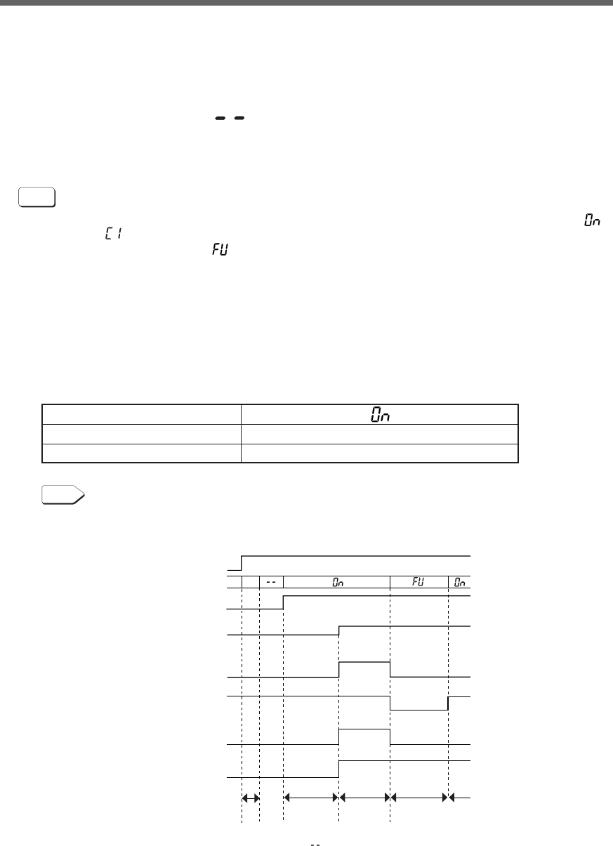
36
3. Operation
See also
Cold start ON/OFF setting ➛ Page 49
• During operation, the battery is charged automatically.
Status indicator
Beep
Power supply output receptacles
None
Outputs power (connected devices are powered)
3-2 Start and stop procedures and basic operation
●When the power switch is OFF and the AC input plug is connected to a commercial
power supply:
• The details of the most recent error are displayed. (item 4 on page 40)
•The status indicator displays " ".
•Power output is stopped.
•The battery automatically starts recharging.
●Start procedure
Operation
Turn on the power switch of the UPS.
•Output begins in Bypass Mode about 10 seconds after the switch is activated. (Status indicator “ ”)
However, “ ” is displayed at cold start, and output begins in Battery Mode.
•The status indicator displays “ ”, and the self-diagnostic test is performed in Battery Mode for about
10 seconds. (If the battery voltage is low, the self-diagnostic test is not performed. It is automatically
executed after the battery is charged.)
*1 When the self-diagnostic test finishes successfully, switching to AC output from commercial power
is performed and normal operation starts.
*2 Self-diagnostic test is not performed at cold start.
•If the self-diagnostic test is finished normally, It is replaced by the AC output from a commercial power
supply and become a normal driving state through inverter mode.
•If the self-diagnostic test is not executed, the UPS immediately starts outputting AC from commercial
power.
ON
OFF
ON
OFF
ON
OFF
ON
OFF
Commercial Power
Battery
Bypass
Inverter
Commercial Power
Battery
D-1
<Note>
D-1 : The most recently displayed error code (refer to item 4 on page 34)
(If no errors have occurred, " " is displayed.)
Commercial
operation
AC input
7 seg.
Power supply SW
Power supply
output lamp
Bypass operation
lamp
Operating mode
Operating mode
Output
Startup
preparation
about
10 sec.
about
10 sec.
about
2 to 3 sec.
Bypass
mode
Self-diagnostic
test
1 sec.
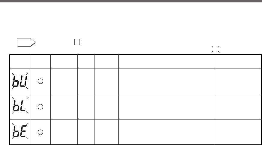
37
3. Operation
●Operation after a power failure
•If a power failure or abnormal input power supply occurs, the UPS automatically switches to Battery
Mode, continuing power output from the Power Supply Output Receptacles supplied from the battery.
• The status is displayed and the beeper sounds intermittently to alert the user.
See also
Setting switch 1 can be used to turn the beeper ON/OFF. ➛ Page 43
Status
indicator
Battery
replacement
Beep Output Charging Description Solution
Intermittent
4-second
intervals
Intermittent
1-second
intervals
None
OFF
Discharging
ON
OFF
Discharging
ON
OFF
Discharging
OFF
In Battery Mode due to power failure or
AC power error.
Perform shutdown
operations for the
connected devices
and stop them.
(Same as above.)
Battery level is low, so output will stop soon. (Same as above.)
Battery is dead, so output stopped.
(This is displayed only for a few seconds.) Charge the battery.
( indicates blinking)
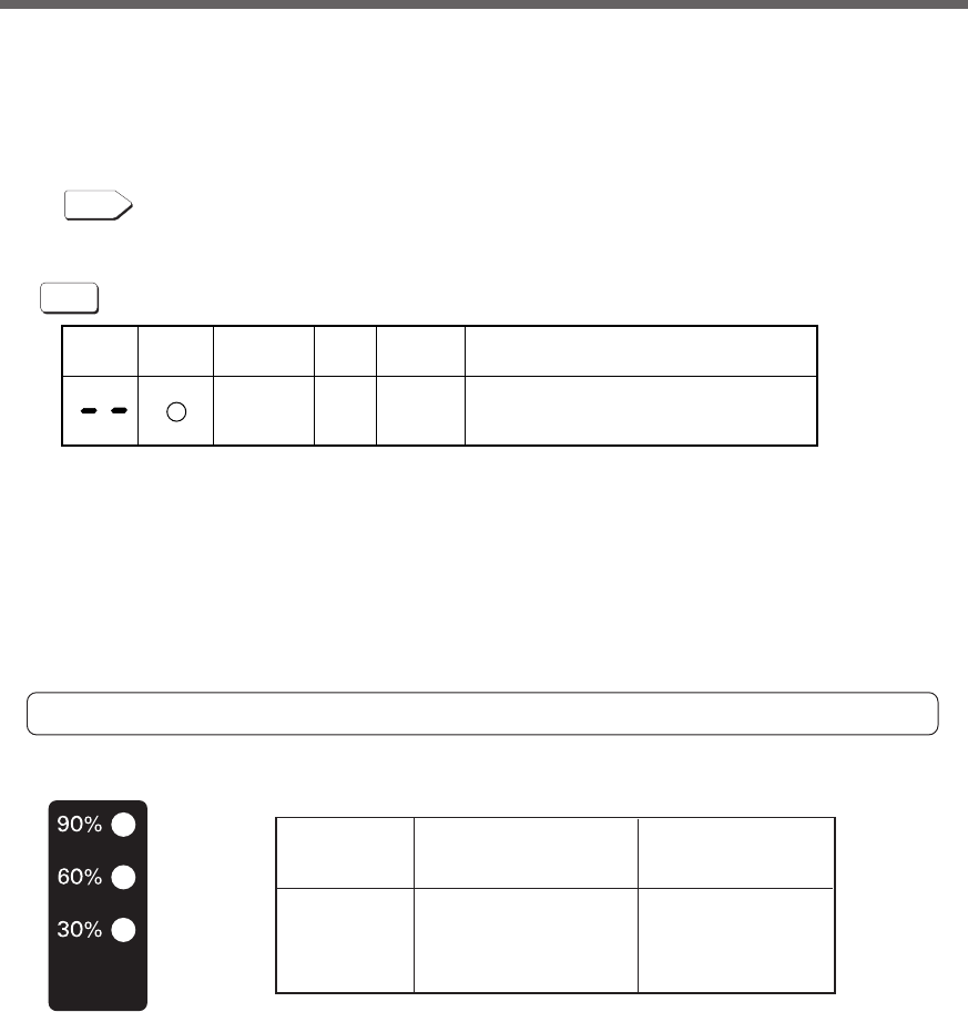
38
3. Operation
● Connection capacity/battery level meter
In Commercial Power Mode (normal operation), the power consumption of devices connected to the capac-
ity/battery level meter is displayed as a percentage.
BU1002SW: Displayed in 3 levels, with 1000VA/700W as 100%.
BU3002SW: Displayed in 3 levels, with 3000VA/2100W as 100%.
When the power consumption of connected devices is 30% or less, the level meter turns OFF.
In Battery Mode, the battery level is displayed as a percentage.
Connection
capacity
Battery level
●Operation during recovery from a power failure
•If a power failure or abnormal power input is resolved while the UPS supplies power, it returns to the
commercial power output status automatically. Charging the consumed battery starts.
• If a power failure or abnormal power input is resolved after the battery is discharged completely and
power output is stopped, the UPS restarts automatically and resumes power output. The expended
battery begins to charge.
See also
Setting switch 2 can be used to select whether or not auto restart is performed. See Page 43
●Stop procedure
Operation
Turn ON the power switch of the UPS.
• The power output from the UPS stops.
•Even if you turn off the power switch, if AC is supplied from commercial power, the battery is automati-
cally charged.
Status
indicator
Battery
replacement
Beep Output Charging Description
None ONOFF There is AC input
Power switch “OFF”
90% lamp 90% or more 60% or more
60% lamp 60% or more 30 to 60%
30% lamp 30% or more 0 to 30%
All OFF 30% or less —
In Commercial Power Mode
Connection capacity
Indicator is ON
Indicator is ON In
Battery Mode Battery
level Indicator blinks
* In Commercial Power Mode (normal operation), the battery level is displayed when the beeper stop/
test switch is pressed.
(Please note that if the button is pressed and held for 5 seconds or more, the beeper begins to sound
and the self-diagnostic test starts.)
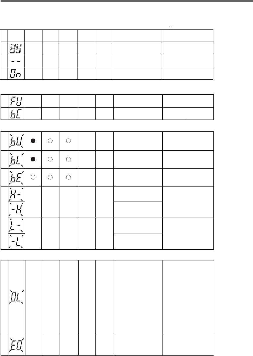
39
3. Operation
3-3 Interpreting beeps and displays
1. Displays and beeps in normal operation
No. Status
indicator
Power supply
output
lamp
Beep Charging Description Solution
1None OFF No AC input.
Operation stopped.
−−
2None ON There is AC input.
Power switch is OFF.
−−
3None ON Power switch is ON.
Operating normally.
−−
○
○
●
○
○
○
Bypass
operation
lamp
○
○
○
Battery
replacement
lamp
( indicates blinking)
( indicates the display is ON)
( indicates the display is OFF)
○
●
2. Displays and beeps while testing
4None
−−
5None
−−
●
●
○
○
○
○
OFF
Discharging
Discharging
Self-diagnostic test in progress.
OFF
Auto battery test in progress.
3. Displays and beeps during power failure or AC input error
6
7
OFF
Discharging
OFF
Discharging
Discharging
8None
OFF
In Battery Mode due to power
failure or AC input error.
Output will stop if Battery
Mode continues.
(Same as above.)
Battery level is low, so output
will soon stop.
Battery is dead,
so output stopped.
(This is displayed only for
a few seconds.)
Intermittent
4-second
intervals
Intermittent
1-second
intervals
(Same as above.)
Perform shutdown operations
for the connected devices
and stop them.
Charge the battery.
9None
○ ○
○
10 None
○ ○
○
(Same as above.)
(ON)
(ON)
Use within the AC input voltage/
frequency range described
in the specifications.
→ See Page 88
AC input voltage is too high
(over).
AC input frequency is too high
(over).
AC input voltage is too low
(under).
AC input frequency is too low
(under).
4. Displays and beeps when there is an equipment failure
●○ ○
ON
or
discharging
ON
or
discharging
○○ ○
11
12
Intermittent
0.5-second
intervals
Continuous
There are too many connected
devices and the rated capacity is
exceeded. If this state continues
for as long as or longer than the
times described below,
commercial power continues
to be supplied through bypass
operation (Note 1).
・
When connection capacity is
at 100% or higher: Bypass
operation begins after 10 seconds
・
When connection capacity is
at 120% or higher: Output stops
after 1 minute (Go to No.12)
・
When connection capacity is
at 140% or higher: Output stops
after 10 seconds (Go to No.12)
Reduce the number of connected
devices until the display appears
as in status No. 3.
Turn OFF the power switches of
all devices connected to the unit,
reduce the number of connected
devices, and turn the power switch
back ON again.
Output stopped due to exceeded
connection capacity.
40
3. Operation
○
●
○
●
○
○ON
or
discharging
ON
or
discharging
○
13
14
15
●● ○
16
●● ○
17
●○ ○
18
See also
――――
(Note 3)
――
(Note 3)
――
(Note 3)
――
(Note 3)
――
――
――
Failure occurred. When the beep
stop switch is pressed, the details
of the error are displayed
(Nos. 16 to 23).
Turn OFF this unit and all connected
devices. Then, turn the power switch
back ON for this unit only. If the display
does not change, there is a problem
with this unit. Contact the shop of
purchase or our peripheral device
customer support center at: _____
Moved to bypass operation due
to output voltage error (over)
(Note 1).
Displays the details of the error that
occurred only while pressing the beep
stop switch while in state No. 15.
Moved to bypass operation due
to output voltage error (under)
(Note 1). (Same as above.)
Moved to Battery Mode due to
battery charge voltage error (over).
Output will stop when the battery is dead.
(Same as above.)
○○○
19 ――
(Same as above.)
●● ○
20 ――
(Same as above.)
●● ○
21 ――
(Same as above.)
○
22 ――
(Same as above.)
Output stopped because the
output of the battery charge
voltage short-circuited.
Moved to bypass operation due
to problem with the internal
temperature (Note 1).
Moved to bypass operation due
to bypass bus voltage error
(Note 1).
(1) Output stopped due to
system error.
(2) Other error occurred.
Continuous
Continuous
Continuous
Replace the external cooling fan.
The fan can be replaced via the
rear panel without stopping
this unit
.
Use replacement fan sold separately.
(Note 2)
“Replacing the fan” Page 62
Continuous
Continuous
Continuous
Continuous
Continuous
Continuous
Continuous
Note 1: In bypass operation, commercial power is output directly. Output stops when a power failure (AC input OFF)
occurs in bypass operation.
Note 2: Fan replacement performed by the user does not comply with UL, CE standards.
Note 3: The displays and operations vary according to the status.
Output stopped due to output
short-circuit.
Moved to bypass operation due
to problem with the external
cooling fan (Note 1).
Check that the AC input of
connected devices is not
short-circuited.
No. Status
indicator
Power supply
output
lamp
Beep Charging Description Solution
Bypass
operation
lamp
Battery
replacement
lamp
4. Displays and beeps when there is an equipment failure
(continued)
( indicates blinking)
( indicates the display is ON)
( indicates the display is OFF)
○
●
5. Display and beep for battery replacement
23
●○
The battery test detected
a weak battery
(warning only, output continues).
Replace the battery.
You can replace the weak battery
with a separately purchased
replacement battery as needed.
Intermittent
2-second
intervals
ON
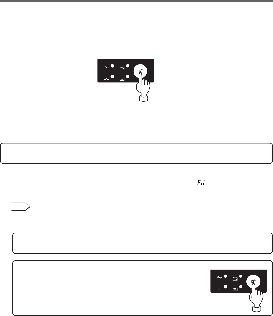
41
4. UPS functions
4. UPS functions
4-1 Suspending a beep
When the beep is sounding, you can suspend it by pressing and holding the beep stop/test switch for 0.5
seconds or longer.
4-2 Self-diagnosis test
This test performs a failure diagnosis on the unit and performs a simple test to check for battery deterioration.
Use the procedure below to check whether a circuit failure has occurred inside the unit and whether battery
replacement is required.
If the battery is not fully charged, the self-diagnostic test is not executed immediately.
After charging is complete, it is automatically executed.
(1) Connect your computer and other devices to the UPS and then turn ON the power switch of the UPS.
(2) The Battery Mode starts for testing purpose automatically (Status indicator “ ”). (No beep sounds.) After
about 10 seconds, when the test is complete the normal operation automatically starts.
(3) If the status indicator/battery replacement lamp blinks and the beeper sounds:
See also
"3-3 Interpreting beeps and displays" ➛ Page 39
Follow the directions for the solutions described in “4. Displays and beeps when there is an equipment
failure” and “5. Display and beep for battery replacement”.
*This test can also be run from the included UPS monitoring software.
For more details, refer to the online help for the UPS monitoring software.
-
バッテリ
交換
バッテリ
増設
ブザー停止/テスト
電源出力
バイパス
運転
-
バッテリ
交換
バッテリ
増設
ブザー停止/テスト
電源出力
バイパス
運転
This test can also be performed manually.
Press and hold the Beep Stop/Test Switch of the UPS for 5 second or longer.
When the beeper begins to sound intermittently, release the Switch.
42
4. UPS functions
4-4 Changing the setting of the functions
4-3 Description of the auto battery test function
This test performs a failure diagnosis on the unit and performs a test to check for battery deterioration.
(This test is more accurate than the self-diagnostic test.)
This test is performed automatically. (You do not have to perform any special operations.)
The test is performed at intervals of 4 weeks after the AC Input Plug is connected to a wall outlet (commercial
power).
The test is not performed if the power switch is OFF or if the battery is not fully charged.
(1) When the auto battery test starts, the Battery Mode automatically starts (Status indicator “ ”). (No beep
sounds.) After the auto battery test is complete, the normal operation automatically starts.
(2) If the status indicator/battery replacement lamp blinks and the beeper sounds:
See also
"3-3 Interpreting beeps and displays" ➛ Page 39
Follow the directions for the solutions described in “4. Displays and beeps when there is an equipment
failure” and “5. Display and beep for battery replacement”.
-
バッテリ
交換
バッテリ
増設
ブザー停止/テスト
電源出力
バイパス
運転
ON DIP
1 2 5678
3 4
1. Selecting functions with the DIP switch
The setting switch on the Front of the UPS allows you to select the "disable the auto battery test" setting.
See also
"4-4 Changing the setting of the functions" ➛ Page 42
See "Setting for whether or not to perform battery test"
This test can also be performed manually.
Press and hold the Beep Stop/Test Switch of the UPS for 10 second or longer.
When the beeper changes from intermittent beeps to a sustained beep, release the switch.
Caution
After changing the setting switch, disconnect the AC input plug, wait until the
status indicator is completely OFF, and then reinsert the AC input plug.
● The setting switch changes do not become valid until the AC input plug is reinserted.
•Use a fine-pointed tool such as a small screwdriver to maneuver the switch’s lever.
43
4. UPS functions
●Setting for beeper sound in the event of power failure, etc. (setting switch 1 )
… Factory setting: OFF
OFF: The beeper sounds when an alarm is necessary.
ON: The beeper does not sound for backup operation or battery replacement. The beeper sounds for
other errors (connection capacity exceeded, operation error, etc.).
ON DIP
1 2 5 6 7 83 4
OFF: Automatically starts when power is restored.
After a power failure occurs and the unit shuts down using the shutdown software or contact signal(BS
signal), the unit automatically starts and begins to output when the commercial power is restored.
ON: Does not automatically start when power is restored.
After the unit is shut down with the UPS monitoring software or contact signal (BS signal), it does not
start up when commercial power is restored. Startup is performed by turning the power switch OFF
once, and then back ON again.
1 2 53 4 86 7
ON DIP
●Auto startup setting after recovery from power failure (setting switch 2 )
… Factory setting: OFF
No.
1
2
3
4
5
6
7
8
OFF side ON side
* In the factory settings, everything is OFF.
Function to set
Setting for beeper sound in the
event of power failure, etc.
Auto startup setting after
recovery from power failure
Setting for whether or not to
perform battery test
Auto startup mode setting
---
---
BS signal valid range setting
---
Beeper does
not sound
Do not perform
auto startup
Do not perform
test
Mode B
---
---
Valid only during
Battery Mode
---
Beeper sounds
Perform auto startup
Perform test
Mode A
---
---
Always valid
---
Setting switch function list
44
4. UPS functions
●Setting for whether or not to perform battery test (setting switch 3 )
… Factory setting: OFF
1 2 53 4 86 7
ON DIP
OFF: The battery test is automatically executed once every 4 weeks.
ON: Does not perform the auto battery test.
Use this setting to disable Battery Mode for for the regularly performed auto battery test.
●Auto startup mode setting (setting switch 4 ) … Factory setting: OFF
OFF: (Mode A) After UPS stopped, the UPS is automatically started immediately when “ON” is
detected for the AC input.
ON: (Mode B) After UPS stopped, the UPS is automatically started in the AC input’s “OFF to ON” timing
that is detected.
(Definition of AC input OFF: When AC input is OFF for 1 second or more)
* Setting switch 4 is valid when the auto startup after recovery from power failure setting (setting switch 2)
is set to OFF (auto restart is performed).
*This setting mode is valid only after the UPS has been stopped by the contact signal backup stop signal
(BS).
*When a cable is connected to the RS-232C connector and the UPS monitoring software is used, the unit
operates in Mode A regardless of this setting.
1 2 53 4 86 7
ON DIP
45
4. UPS functions
(1) When BS signal is used to stop the UPS after a power failure occurs
(1)-1.
(2) When BS signal is used to shut down the UPS when AC input is ON
AC input
Power output
(Setting switch 4 OFF:
Mode A)
Power output
(Setting switch 4 ON:
Mode B)
ON
OFF
ON
OFF
ON
OFF
ON
OFF
BS signal
*1
*1
Starts up when BS signal
turns OFF
Starts up when AC input
turns from OFF to ON
ON
OFF
ON
OFF
ON
OFF
ON
OFF
1 sec
AC input
Power output
(Setting switch 4 OFF:
Mode A)
Power output
(Setting switch 4 ON:
Mode B)
BS signal
* 1: BS signal reception time corresponds to the setting switch 7.
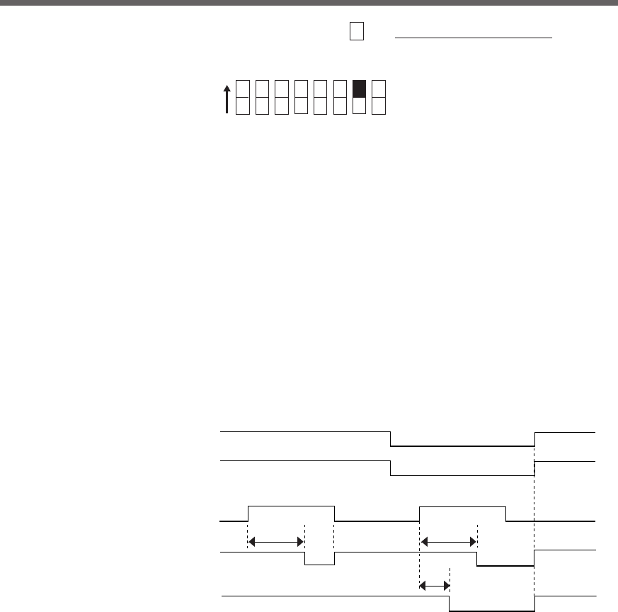
46
4. UPS functions
●BS signal valid range setting (setting switch 7 ) … Factory setting: OFF
OFF: The BS signal is always valid (receivable).
The unit’s “power output ” can be stopped by inputting a “ON” backup power supply stop signal
(BS) that continues for 10 seconds or more.
ON: The BS signal is valid (receivable) only when in Battery Mode. (The signal is not received when in
Commercial Power Mode.)
The unit’s “power output ” can be stopped by inputting a “ON” backup power supply stop signal
(BS) that continues for 0.01 (10 ms) seconds or more.
Use this setting in commercial operation when you do not want to stop operations when a backup
power supply stop signal (BS) is received.
•Auto startup operation when power is restored
Auto startup when power is restored is associated with setting switch 2.
However, the unit does not start up when the BS signal is ON.
1 2 53 4 86 7
ON DIP
*1*1
*1
AC input
●BS signal valid range setting (setting switch 7 )
BS signal
Power supply output
(Setting switch OFF)
Power supply output
(Setting switch ON)
Note 1: Operation when setting switch 2 is OFF (auto startup is performed). When it is ON (auto startup is not performed) auto startup is not performed.
10 sec 10 sec
0.01 sec
ON
OFF
ON
OFF
ON
OFF
ON
OFF
Commercial Power Mode
Battery Mode
Operationg Mode
47
4. UPS functions
ON
OFF
ON
OFF
ON
AC input
BS signal
Power supply
output OFF
Power output stop delay time
This timing is 10 ms or 10 sec.
Timing corresponds to the settings
for switch 7 .
3) Power output stop delay time setting
It is possible to set the delay time for stopping the power supply output after the BS signal is
received. (Setting range: 0 to 10 minutes)
<Note>
The remote ON/OFF signal is not related to this setting.
When the remote ON/OFF signal is “High”, the UPS stops the output immediately.
See also
➛ Page 46
2. UPS operation mode settings
2-1 Settable items and explanations
There are 4 items to select.
1) Cold start ON/OFF setting
2) Output voltage setting
3) Power output stop delay time setting
4) Signal input/output test
The settings available for this operation are shown below.
1) Cold start ON/OFF setting
• Cold start OFF mode
The unit can start up only when there is AC input.
• Cold start ON mode
It is possible to start up the unit even when there is no AC input plug.
(It is not possible, however, to start up the unit by the remote signals.)
Normal operation occurs when AC input is ON. The output frequency is the same as the frequency
the last time there was AC input.
2) Output voltage setting (200V/220V/230V/240V)
Four types of output voltage can be set. (Setting range: 200V/220V/230V/240V)
Output is performed at the set voltage, with no relation to the input voltage.
48
4. UPS functions
Output signal Input signal
Battery Low signal (BL)
(Between pins 1 and 5)
Trouble signal (TR)
(Between pins 2 and 5)
Backup signal (BU)
(Between pins 8 and 5)
Deteriorated battery
signal (WB)
(Between pins 9 and 5)
Backup power supply
stop signal (BS)
(Between pins 3 and 5)
Remote ON/OFF signal
(Between pins 6 and 7)
While the signal is being input, these status
indications blink and the beep sounds.
Beep
Signal input/output test start
ON
OFF
ON
OFF
ON
OFF
ON
OFF
ON
OFF
ON
OFF
ON
OFF
Signal output test
Contact signal is forced to turn ON.
Signal input test
While the signal is being
input, the status indicator
blinks and the beep sounds.
Signal input/output test end
4) Signal input/output test (BL/TR/BU/WB/BS/remote)
●Four types of output signal can be forcibly turned ON.
●The ON/OFF state of two types of input signal can be checked with the status indicator and the
beeper.
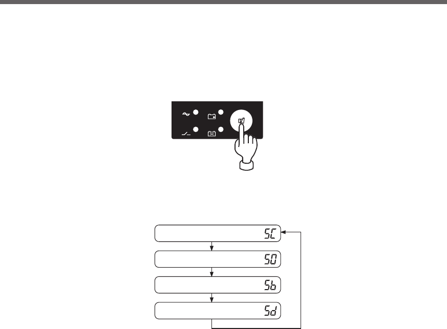
49
4. UPS functions
(1) When the beeper stop switch is briefly pressed (for less than 1 second), the next item is displayed.
(2) The unit enters the “individual item setting mode” when the beeper stop switch is pressed and held
(for more than 1 second).
(3) When the power switch is turned OFF, the setting mode quits and the unit enters power switch OFF
status (status No.2).
Cold start ON/OFF setting
Output voltage setting
Power supply output stop delay time setting
Signal input/output test
-
バッテリ
交換
バッテリ
増設
ブザー停止/テスト
電源出力
バイパス
運転
The UPS operation mode can be set if the power switch is turned ON while the beeper stop switch is
pressed.
Note: While in setting mode, output from the power supply output is OFF even if the power switch is ON.
2-2 Settings
50
4. UPS functions
ON Cold start ON mode
C
C *1
C
C
C *1
C
C *1
C
DD
D
D
D
D
D
D
D
D
D
D
D
D
D
D
D
D
D
D D
D
A B
OFF Cold start OFF mode (Factory-shipped setting)
Remote Remote ON/OFF signal output test
BL Battery low signal output test (Factory-shipped setting)
BS Backup power supply stop signal output test
Signal input/output
test
TR Trouble signal output test
BU Backup signal output test
WB Battery replacement signal output test
*1 Displays the current setting value.
Cold start
ON/OFF setting
Setting mode
Normal status
Output voltage
setting
Output voltage
setting
200V Output 200V mode (Factory-shipped setting)
220V Output 220V mode
230V Output 230V mode
240V Output 240V mode
10 minute delay
0 minute delay (Factory-shipped setting)
2 minute delay
0.2 minute delay
0.5 minute delay
1 minute delay
There is AC input
Power switch “OFF” (Status No. 2) B
C
D
ATu rn ON the power switch while the beep stop/test switch is pressed.
Tu rn OFF the power switch.
Press and hold the beep stop/test switch (for more than 3 seconds).
Press the beep stop/test switch (for less than 3 seconds).
51
5. Measuring the backup time
5. Measuring the backup time
5-1 How to measure backup time
(1) When the AC input plug is connected to a wall outlet (commercial power), the battery automatically starts
charging, taking up to 8 hours to complete (24 hours when an additional battery unit is connected).
(2) Turn ON all devices connected to the power output to be “backed up during a power failure”.
(This includes devices connected to the AC outlet of your computer.)
Operate the connected devices in a way that allows the power supply to be stopped at any time.
●For Windows Server 2003/XP/Me/2000/Windows NT/Linux/Mac:
Perform measurement while the hard drive is stopped.
●For Windows 98/95:
Choose "Shut Down" in Windows and follow the procedure below to shut down your OS.
Choose "Restart in MS-DOS mode" to exit from OS and display the MS-DOS mode screen.
(3) Disconnect the AC Input Plug of the UPS and measure the backup time.
Measure the time until the unit automatically stops and all displays disappear with the plug disconnected.
* The backup time you measure for the first time after purchase is the "initial value of the backup time."
5-2 Estimated backup time
The backup time varies depending on the capacity of connected devices.
After calculating the total capacity of connected devices, refer to the graph of the backup time to obtain an
estimation of the initial value of the backup time. (This is also applied to checking the battery.)
(1) Convert the total capacity (power consumption) of the connected devices to watts (W).
For the indication of connected devices, check your computer and the rear of the display.
The indicator can show values in three different ways: volt-amperes (VA), amperes (A), and watts (W).
Example 1) 200 VAC, 50/60Hz, 145 W
Example 2) 200 VAC, 50/60Hz, 1.8 A
Example 3) 200 VAC, 50/60Hz, 150 VA
For devices that use the VA or A indication, convert the capacity into W. Multiply the value indicated on
devices by the value in the right table for conversion.
(When the power factor is unknown, enter “1”. The power factor usually ranges between 0.6 and 1.)
(2) Add the values converted into W to obtain the total capacity of the connected devices.
Caution
Never touch the metal part of the input plug if it is disconnected while the
unit is operating.
●Doing so may cause an electric shock.
●The leak current of this product itself is less than the value of the safety standard (leak current:
1 mA). However, leak current increases due to connected equipment. Therefore, never touch the metal
part of the input plug.
●When the product is operating, voltage is generated at the metal part of the input plug via capacitors in
the internal circuit regardless of elapsed time.
Indication Value
VA × power factor = W
A× power factor × 200 = W
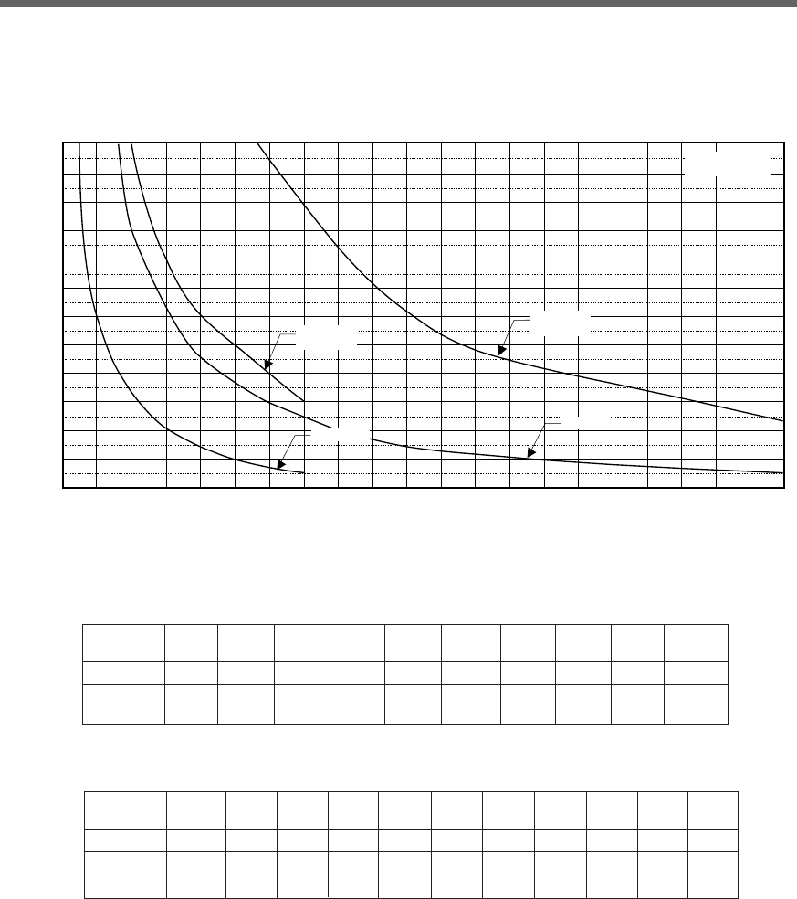
52
5. Measuring the backup time
(3) Calculate the initial value of the backup time for the total capacity of the connected devices from the graph
below.
●Graph of backup time (graph of initial values for products that have not been used)
●The smaller the capacity of connected devices becomes, the longer the backup time becomes.
120
110
100
90
80
70
60
50
40
30
20
10
0
0 100 200 300 400 500 600 700 800 900 1000 1100 1200 1300 1400 1500 1600 1700 1800 1900 2000 2100
Backup time
(20°C, initial value)
BU1002SW
BU3002SW
BU1002SW +
BUM100S
BU3002SW +
BUM300S
(Minutes)
Power consumption
of connected devices(W)
* These backup times are for reference only. Times may vary according to battery life and external
environmental conditions (temperature, etc.).
Time unit: Minutes
Model 20W 50W 100W 200W 300W 400W 500W 700W 1000W 1400W
BU1002SW 180 120 60 35 20 15 10 5
--
720 420 240 120 80 60 50 30
--
BU1002SW+
BUM100S
Model 200W 400W 600W 800W 1000W 1200W 1400W 1600W 1800W 2000W 2100W
BU3002SW 92 46 30 20 15 12 10 8
75.5 5
BU3002SW 340 175 115 85 62 49 43 37
31 26 24
+ BUM300S
53
6. Maintenance and inspection
When maintaining the connected equipment, turn OFF the power switch
and disconnect the AC input plug.
●Even if you disconnect the AC input plug while the UPS is operating, the power output of this
unit does not stop and power is supplied from the outlet during a power failure.
Do not disassemble, repair, or modify the unit.
●Doing so may cause an electric shock or a fire.
If fluid leaks from the unit, do not touch the fluid.
●Doing so may cause blindness or burns.
●
If the fluid contacts your eyes or skin, wash it out with lots of clean water and consult your doctor.
Do not throw the unit into fire.
●The lead battery in the unit may explode, or leak dilute sulfuric acid.
Do not insert metal objects into the power supply output receptacles of the UPS.
●Doing so may result in electric shock.
Do not insert metal objects into the battery connectors.
●Doing so may result in electric shock.
6. Maintenance and Inspection
Ambient temperature
20°C
30°C
Life of battery
4 to 5 years
2 to 2.5 years
Replacement estimation
4 to 5 years after staring use
2 years after staring use
6-1 Checking the battery
The sealed lead battery used in the unit has a limited life.
(The life varies depending on your storage/use environment and backup frequency.)
The nearer the end of the life is, the more rapidly deterioration proceeds.
1. Life of battery (estimated replacement timing)
2. Methods for checking the battery
There are 3 methods for checking the battery.
•Perform a self-diagnostic test. (See page 41.)
• Use the auto battery test function. (See page 42.)
• Measure the backup time. (See page 51.)
By measuring the backup time, the battery life can be determined more accurately.
See also
Measure the backup time according to "5-1 How to measure backup time"
➛ Page 51
If the measured value is equal to the "initial value of the backup time" or less than half the value obtained
from the graph of "Estimated backup time" on page 46, replace the battery.
•When you compare the "initial value of the backup time" you measured and the current backup time,
make the capacity of devices connected to the UPS same as when you measured the initial value to
make judgment accurately.
Caution (for maintenance)
54
6. Maintenance and inspection
Perform replacement on a stable and flat place.
●Handle the battery carefully so that you do not drop it.
●Not doing so could cause injury or burns due to liquid (acid) leakage.
Use a specified battery for replacement.
●Not doing so may cause a fire.
●Product model: BP100XS (Replacement battery pack for BU1002SW)
BP150XS: Two required (Replacement battery pack for BU3002SW)
Do not replace the battery in a place where there is flammable gas.
●Spark may occur when connecting the battery, which may cause an explosion or fire.
If fluid (dilute sulfuric acid) leaks from the battery, do not touch the fluid.
●Doing so may cause blindness or burns.
●If it contacts your eyes or skin, wash it out with lots of clean water and consult your doctor.
Do not disassemble or modify the battery.
●Doing so could cause dilute sulfuric acid leak, which could cause blindness and burns.
Do not drop the battery and do not expose it to strong impact.
●Dilute sulfuric acid may leak.
Do not short the battery with metal objects.
●Doing so could cause an electric shock, fire or burn.
●Some electrical energy still remains inside the spent battery.
6-2 Replacing the battery
The battery can be replaced while the unit is stopped (power supply output stopped).
*When replacing the battery, stop the connected devices, turn OFF the power switch of the UPS, and
disconnect the AC input plug from the wall.
*If an input power supply error such as a power failure occurs when replacing the battery while in opera-
tion, backup cannot be performed and output stops.
*Do not replace the battery during backup operation. Output will stop.
Caution
When the unit is used in compliance with UL standards or CE marking, do not replace the battery while in
operation (while power is being output). Replacing the battery while in operation does not comply with UL
standards or CE marking. Make sure to stop the operation of the unit before replacing the battery.
3. Guidelines for how often to check the battery (measure the backup time)
*The battery deteriorates even if it is stored. The higher the temperature is, the shorter the
life becomes.
Ambient temperature
20°C
30°C
Check once every 6 months
For the first 3 years after purchase
For the first 1.5 years after purchase
Check once a month
When 3 or more years have passed since purchase
When 1.5 or more years have passed since purchase
Caution (for battery replacement)
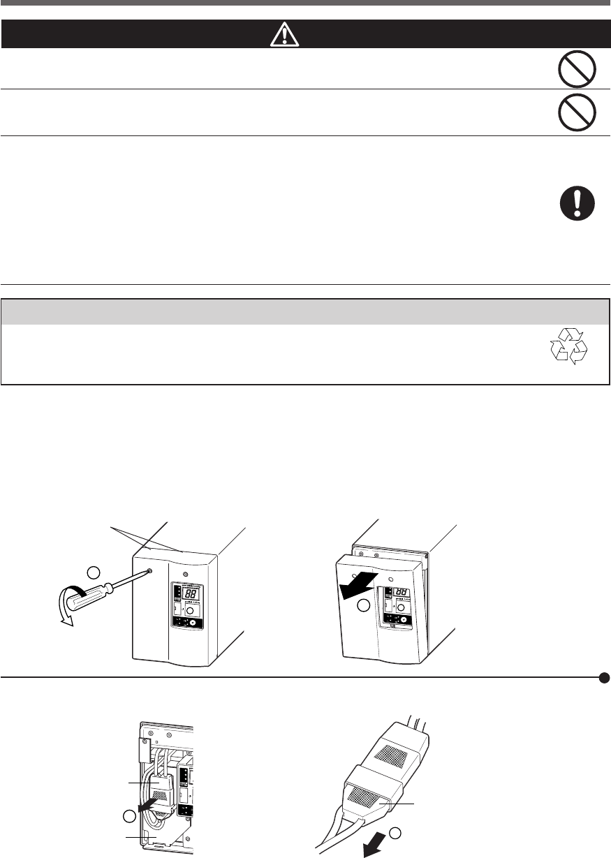
55
6. Maintenance and inspection
90%
50%
30%
-
バッテリ
交換
バッテリ
増設
ブザー停止/テスト
電源出力
バイパス
運転
2
90%
50%
30%
-
バッテリ
交換
バッテリ
増設
ブザー停止/テスト
電源出力
バイパス
運転
1
Notes
Battery recycling
The unit uses lead acid batteries, which are a valuable recyclable resource. Please recycle.
For information on recycling, please contact our peripheral device repair center. Pb
Caution (for battery replacement)
Do not put the battery into fire and do not break it.
●The battery may explode or leak dilute sulfuric acid.
Do not use a new battery and an old battery at the same time.
●Dilute sulfuric acid may leak.
●A battery can present a risk of electrical shock and high short circuit current.The following
precautions should be observed when working on batteries:
1) Remove watches, rings, or other metal objects from the hands.
2) Use tools with insulated handles.
3) Wear rubber gloves and boots.
4) Do not lay tools or metal parts on top of batteries.
5) Disconnect charging source prior to connecting or disconnecting batteries terminals.
●Servicing of batteries should be performed or supervised by personnel knowledgeable of
batteries and the required precautions. Keep unauthorized personnel away from batteries.
■ Procedure for recycling the battery
<BU1002SW>
1. Use a screwdriver to loosen (turn clockwise) the 2 screws at the top of the front panel of the unit, until they
turn freely. (The screws cannot be removed from the front panel.) ➀
Pull the front panel towards you to remove it. ➁
Loosen the
2 screws.
Battery connector
Plate cover
Disconnect by holding here.
2. Remove the battery connector from the plate cover ➀ and disconnect the connector. ➁
90%
50%
30%
-
バッテ
交
換
バッテ
増
設
電源出力
バイパス
運転
1
2
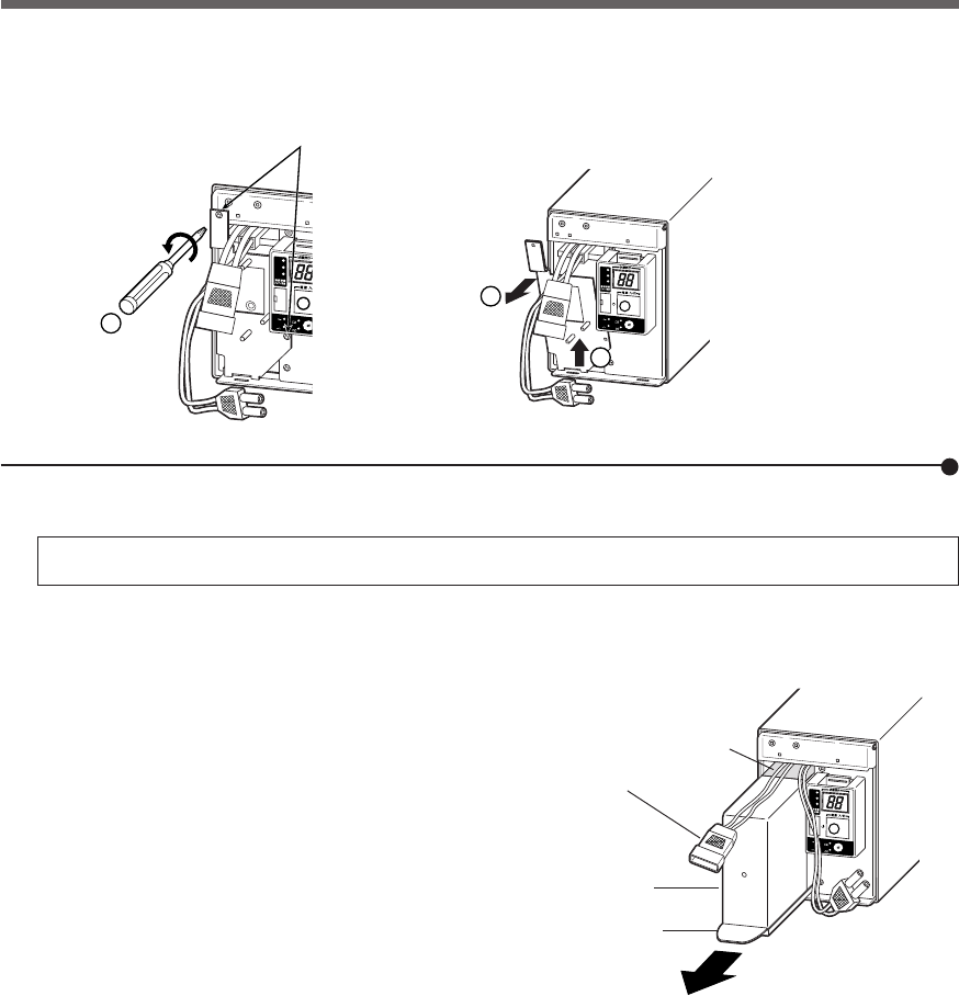
56
6. Maintenance and inspection
90%
50%
30%
-
バッテリ
交換
バッテリ
増設
ブザー停止/テスト
電源出力
バイパス
運転
3. Turn the 2 screws that fix the plate cover counterclockwise to remove them. ➀
Pull the plate cover towards you ➁ and lift it up to remove it. ➂
Remove the 2 screws.
4. Hold the pullout label at the bottom of the battery pack and remove the battery pack.
Do not hold the connector or cable of the battery pack.
Use the red tape on the top of the battery pack, which is 10 cm from the inner edge of the battery, to gauge
how much further you need to pull the battery to remove it. Hold the battery securely with both hands so as
not to drop it.
2
3
90%
50%
30%
-
バッテリ
交換
バッテリ
増設
ブザー停止/テスト
電源出力
バイパス
運転
90%
50%
30%
-
バッテリ
交換
バッテリ
増設
ブザー停止/
テ
電源出力
バイパス
運転
1
Battery connector
Battery pack
Pullout label
(Pull this to remove.)
Red tape
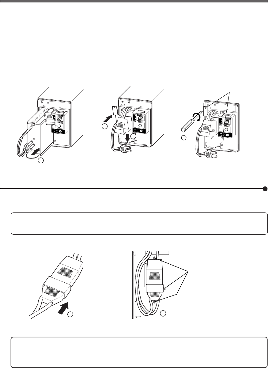
57
6. Maintenance and inspection
90%
50%
30%
-
バッテリ
交換
バッテリ
増設
ブザー停止/テスト
電源出力
バイパス
運転
4
90%
50%
30%
-
バッテリ
交換
バッテリ
増設
ブザー停止/テスト
電源出力
バイパス
運転
1
3
2
90%
50%
30%
-
バッテリ
交換
バッテリ
増設
ブザー停止/テスト
電源出力
バイパス
運転
Tighten the 2 screws.
1
2
Secure the connector by
the 3 supports on the
plate cover.
5. Insert a new battery into the UPS as far as it will go. ➀
● Replacement battery pack
For BU1002SW: Model BP100XS
Attach the plate cover.
Insert the lug at the bottom of the cover into the hole in the main body ➁ and push it towards the main body. ➂
Use a screwdriver to securely tighten (clockwise) the 2 screws you removed. √
Do not pinch the cable with the plate cover.
6. Insert the connector until it is locked. ➀
Secure the connector to the plate cover. ➁
You may hear a “pop” sound when you connect the battery if it is replaced
after the unit’s operation is stopped, but this sound is not abnormal.
If you cannot secure the connector to the plate cover, the connector is not
inserted completely.
Insert the connector again.
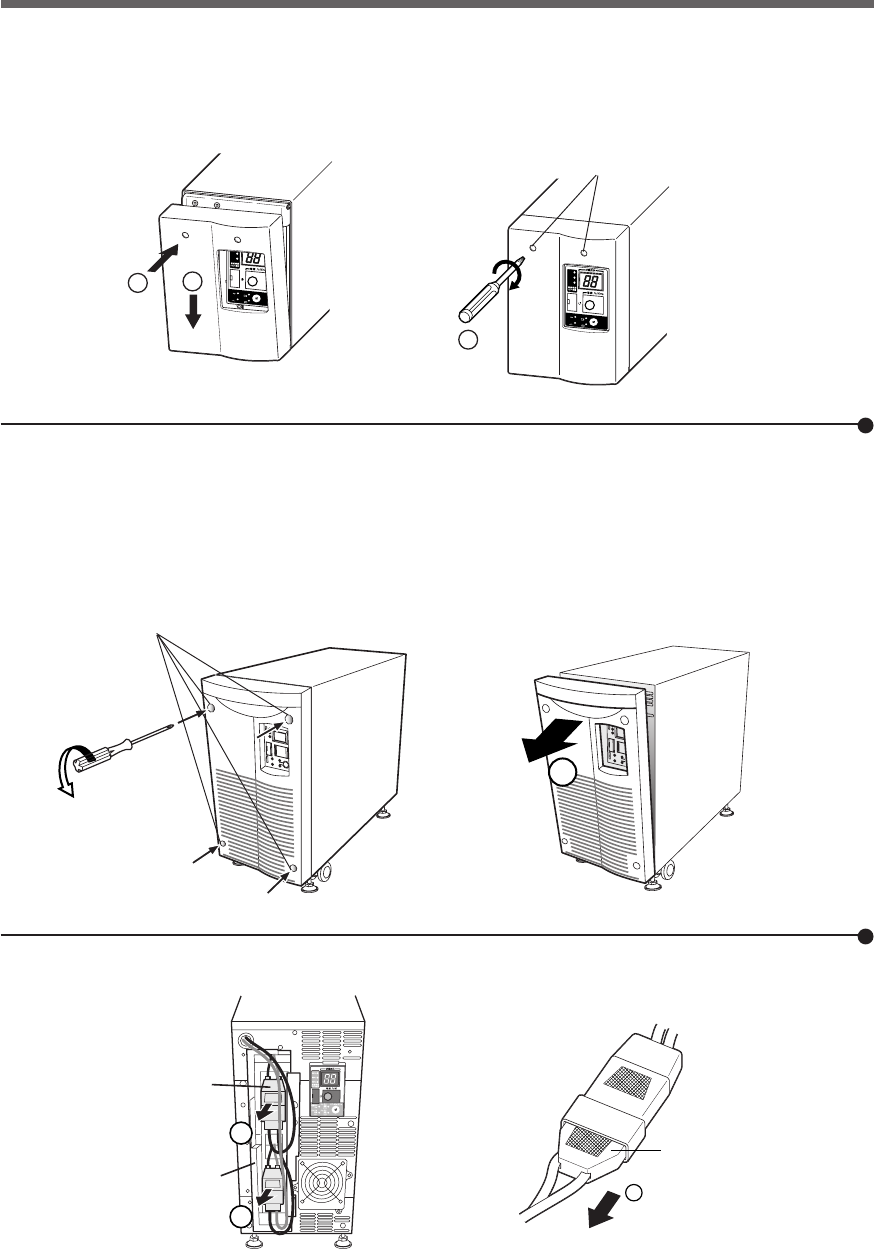
58
6. Maintenance and inspection
7. Attach the front panel.
Insert the lug at the bottom of the front panel into the hole in the main body ➀ and push it towards the main
body. ➁
Use a screwdriver to securely tighten (clockwise) the 2 screws at the top of the front panel. ➂
Battery replacement is now complete.
90%
50%
30%
-
バッテリ
交換
バッテリ
増設
ブザー停止/テスト
電源出力
バイパス
運転
1
2
90%
50%
30%
-
バッテリ
交換
バッテリ
増設
ブザー停止/テスト
電源出力
バイパス
運転
3
■ Procedure for recycling the battery
<BU3002SW>
1. Use a screwdriver to loosen (anti-clockwise rotation) the 4screws on the front panel of the unit, until they
turn freely. (The screws cannot be removed from the front panel.)
Pull the front panel towards you to remove it. ➀
Loosen the
4 screws.
Disconnect by holding here.
2. Remove the battery connectors from the lower plate cover ➀ and disconnect each of the connectors. ➁
2
1
Plate cover
Battery connector
1
1
Tighten the
2 screws.
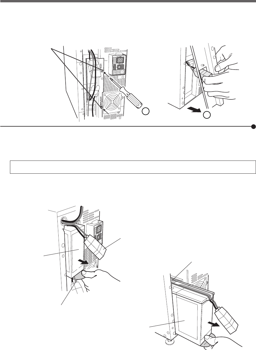
59
6. Maintenance and inspection
3. Turn the 2 screws that fix the plate cover anti-clockwise to remove them. ➀
While pulling the plate cover toward you ➁, lift it up and remove the lower battery connector from the
eyehole.
Battery connector
Battery pack
(Upper)
Pullout label
(Pull this to remove.)
Remove the 2 screws.
4. Hold the pullout label at the bottom of the battery pack and remove the battery pack.
Remove the upper and lower sections one by one.
Do not hold the connector or cable of the battery pack.
Use the red tape on the top of the battery pack, which is 10 cm from the inner edge of the battery, to gauge
how much further you need to pull the battery to remove it. Hold the battery securely with both hands so as
not to drop it.
1
2
Battery pack
(Lower)
Red tape
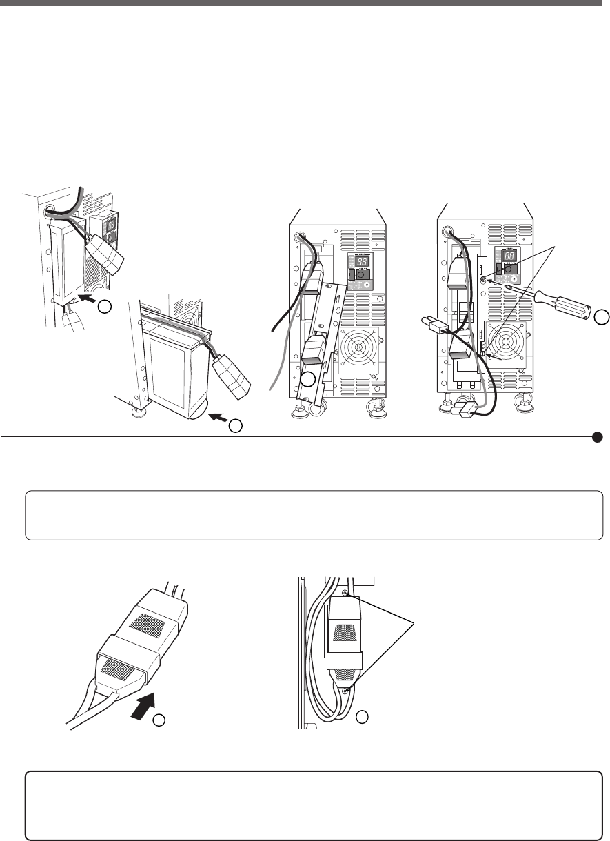
60
6. Maintenance and inspection
1
2
Secure the connector by
the 2 supports on the
plate cover.
5. Insert the new batteries into upper and lower sections as far as they will go. ➀
● Replacement battery pack
For BU3002SW: Model number BP150XS (two required)
Run the top portion of the lower battery connector through the square hole in the plate cover. ➁
Insert the lug at the bottom of the cover into the hole in the main body and push it towards the main body.
Use a screwdriver to securely tighten (clockwise) the 2 screws you removed.➂
Do not pinch the cable with the plate cover.
6. Securely connect the upper and lower connectors. ➀
Secure the connector to the plate cover. ➁
You may hear a “pop” sound when you connect the battery if it is replaced
after the unit’s operation is stopped, but this sound is not abnormal.
If you cannot secure the connector to the plate cover, the connector is not
inserted completely.
Insert the connector again.
1
1
2
Tighten
the 2 screws.
3
61
6. Maintenance and inspection
Write the usage start date on the label on the front. Also, by using the included UPS monitor-
ing software, possible to keep a record of usage start date by the software.
<After replacing the battery when operation was stopped...>
Connect the AC input plug to a wall outlet (commercial power) and turn ON the power switch of the
UPS. When operation starts, the self-diagnostic test is automatically performed. Normal operation
resumes after the 10-second test.
<After replacing the battery during operation...>
If the battery replacement indicator is displayed and the beeper sounds before replacement, press
the beeper stop/test button once to stop the beeper, and hold it for 5 sec. to perform a self-diagnostic
test. The beeper stops and normal operation resumes after the 10-second test is complete.
7. Attach the front panel.
Push the front panel toward the main body. ➀
Use a screwdriver to securely tighten (clockwise) the 4 screws on the front panel.➁
Battery replacement is now complete.
1
2
Tighten the
4 screws.
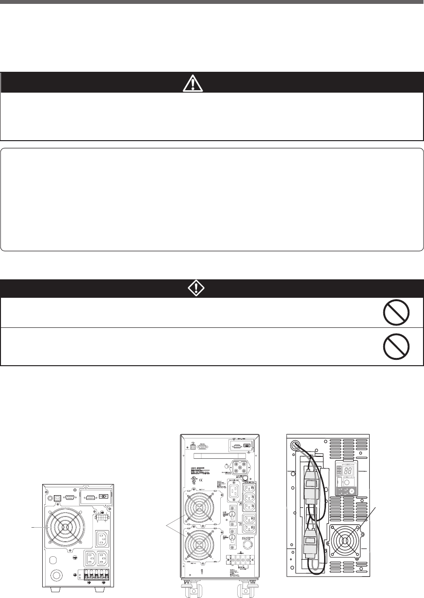
62
6. Maintenance and inspection
6-3 Replacing the fan
The fan in the unit has an expected lifespan of approximately 5 years.
Replace it when the Error Lamp is lit and the fan is stopped.
■ Precautions when replacing the fan
The fan can be replaced while the unit is in operation (power supply is being output) or while the unit
is stopped (power supply output is stopped). Choose whichever replacement method is more
convenient.
*If the fan stops or is removed while the unit is in operation, the “EF” lamp blinks, the beep sounds continu-
ously, and output is supplied through bypass operation.
In this state, if an input power supply error occurs due to a power failure or other reason, the unit stops
without entering Battery Mode.
*Do not replace the fan while in Battery Mode.
The unit will stop.
Do not insert your hand or metal objects into the fan recess.
•Doing so may cause electric shock or short-circuit.
Do not put your fingers into the fan.
•The fan spins when the AC input plug is connected to a wall outlet (commercial power).
•Doing so may result in injury.
Warning
Caution
When this product is used in compliance with UL standards or CE marking, do not
replace the fan.
● Fan replacement does not comply with UL, CE standards or CE marking.
Cooling Fan
Model: BUF1002S
BU1002SW Rear view
BU1002SW Rear view
Cooling fan
Model: BUF1002S
Cooling Fan
Model: BUF3002S
* Different model from
the rear cooling fan
BU3002SW Front view
(after removing the front panel)
-
バッテリ
交換
バッテリ
増設
ブザー停止/テスト
電源出力
バイパス
運転
Detect abnormally working fans.
(Not rotating, abnormal noise, vibrating, the fan contacting the cover, etc)
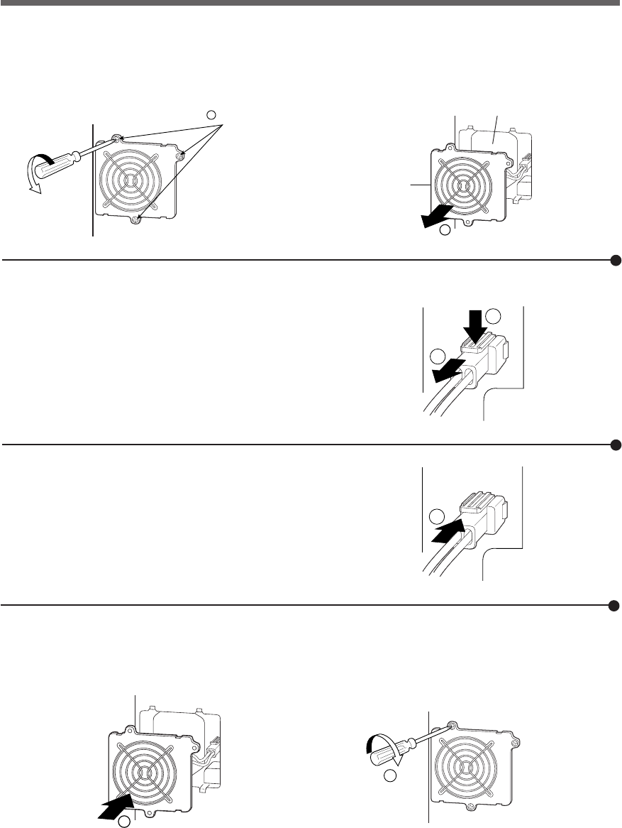
63
6. Maintenance and inspection
1
2
3
1
2
●Replacement fan
For BU1002SW/ BU3002SW rear fan : Model BUF1002S
For BU3002SW front fan : Model BUF3002S
■ Fan replacement procedure
1. Use a screwdriver to loosen (turn counter-clockwise) and remove the 3 cooling fan screws. ➀
Pull the cooling fan toward you to remove it. ➁
1
Loosen the
3 screws.
2
Fan recess
Fan
Fan replacement is complete.
4. Insert the fan into the unit’s fan recess. ➀
Use a screwdriver to securely tighten (turn clockwise) the 3 removed screws. ➁
When doing so, make sure the cable does not become pinned under the fan cover.
3. Insert the new fan connector until it clicks into place. ➂
The beep stops, and the "EF" status display lamp turns OFF.
2. While pressing down on the tip of the fan connector ➀, pull it toward you to disconnect it. ➁
The beep stops, and the error lamp turns OFF.
* Different screw locations for BU3002SW front fan.

64
6. Maintenance and inspection
6-4 Cleaning
1. Cleaning the UPS
Moisten a soft cloth with water or detergent, squeeze it tightly, and wipe the product lightly.
Do not use chemicals such as thinner and benzene. (They cause deformation or discoloration.)
2. Removing dust from the AC input plug, power supply output receptacles and
output terminal block of the UPS
Stop all the connected devices and the UPS and disconnect the AC input plug from a wall outlet (commer-
cial power).
Then, remove dust with a dry cloth and make the connection again.
(For information on the connection procedure:)
See also
"2-3 Connecting the equipment" ➛ Page 24
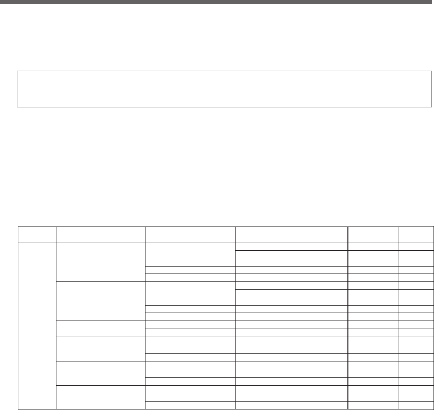
65
7.Using the UPS monitoring software and contact signal
■ UPS monitoring software
“PowerAct Pro (for Windows/Linux)” , “UPS service driver” and “UPS Power Manager (Mac)” UPS monitor-
ing software is included with this product. Refer to the table below for details about compatibility. Choose
which one to use based on the application. Refer to the table below for details about compatibility. For
further details about the software functions, refer to the separate "UPS Monitoring Software Quick Installa-
tion Guide."
7.
Using the UPS monitoring software
and contact signal
*If you do not use the UPS monitoring software and contact signal, this step
is not required.
BU1002SW
BU3002SW
Windows server2003 Serial ⇒See 7-1
x64 Edition (RS232C or USB 1.1) ⇒See 7-2
Windows XP/2000
x64 Edition Contact signal
(Note 2) (Note 4)
⇒See 7-3
LAN ⇒See 8-1
Windows server2003 Serial ⇒See 7-1
Windows XP/2000 (RS232C or USB 1.1)
Contact signal
(Note 2) (Note 4)
⇒See 7-3
LAN ⇒See 8-1
Windows NT 4.0 Contact signal
(Note 2) (Note 3)
⇒See 7-3
LAN ⇒See 8-1
Windows Me/98
Serial ⇒See 7-1
(RS232C or USB 1.1)
LAN ⇒See 8-1
Linux (Note 2)
Serial ⇒See 7-1
(RS232C or USB 1.1)
LAN ⇒See 8-1
Mac OS X (10.3、10.4) Serial (USB1.1) ⇒See 7-1
Mac OS X Server (10.3, 10.4)
(Note 5) LAN ⇒See 8-1
Reference
⇒See 7-2
Model OS Communication method
–
–
BUC26
SC20G
–
BUC26
SC20G
BUC26
SC20G
SC20G
SC20G
SC20G
–
–
Required options
(sold separately)
–
–
Note 1: The most recent version can be downloaded from our homepage (http://www.omron.co.jp/ped-j/download/ups_soft/).
Note 2: Files cannot be automatically saved.
Note 3: To automatically stop the UPS, it may be necessary to change the PC’s BIOS settings.
Change the PC’s BIOS settings so that the PC’s power supply is not cut after OS shutdown is performed.
Note 4: The UPS automatically stops once the battery is depleted.
Note 5: Compatible only with Macintosh computers equipped with PowerPC CPU.
UPS service (OS standard) +
UPS service driver (included software)
UPS service (OS standard)
Shutdown software for SNMP/web card
PowerAct Pro (Note 1)
UPS service (OS standard) +
UPS service driver (included software)
UPS service (OS standard)
Shutdown software for SNMP/web card
UPS service (OS standard)
Shutdown software for SNMP/web card
PowerAct Pro (Note 1)
Shutdown software for SNMP/web card
PowerAct Pro (Note 1)
Shutdown software for SNMP/web card
UPS Power Manager
Shutdown software for SNMP/web card
UPS monitoring software
PowerAct Pro (Note 1)
• UPS monitoring software selection table
66
7.Using the UPS monitoring software and contact signal
[Explanation of software functions]
1 Auto shutdown The computer can be shut down automatically when a problem occurs with the power supply.
2 UPS monitoring (operating status) The operating status of the UPS can be monitored (in Commercial Power Mode/Battery Mode).
3 UPS monitoring (data) Monitoring can be performed for input voltage value, connection capacity, battery capacity, etc.
4 Pop-up notification When a problem such as a power failure occurs, a pop-up window that shows the details of the problem can be displayed.
5 Shutdown when OS is inactive Shutdown can be performed when the computer is in an inactive state.
The operating status is retained at shutdown in inactive state, so operation details are not lost.
6 Auto file save Files such as open Word and Excel documents are automatically saved at shutdown.
7 Schedule operation Schedule settings can be made for UPS stop/start.
8 UPS setting change UPS settings (beep ON/OFF, etc.) can be changed. (Items that can be set vary according to the UPS.)
9 External command execution By executing commands at shutdown, items such as application programs can be launched.
10 Event log save Information of events that occur on the UPS (power supply problems, setting changes, occurrences of failure, etc.) are saved as a log.
11 Data log save Data of input/output voltage value, connection capacity, etc. is periodically saved as a log (the save frequency can be set).
12
Coordinated shutdown When a problem occurs with the power supply, multiple computers connected to the UPS can coordinate to perform auto shutdown.
13 Output receptacle control The UPS output receptacles can be individually set to ON/OFF.
14 Redundant power supply support Two or more UPS can be connected to computers equipped with redundant power supply.
Shutdown is not performed when a power supply proble affects only one of the units.
Shutdown is performed only when a power supply problem occurs with both UPS, so the system's operating rate is improved.
15 Remote UPS management The UPS can be managed remotely from a computer on the network.
16 Mail send When a problem such as a power failure occurs, a notification email describing the problem can be sent to the system administrator.
17 SNMP management UPS management information can be sent to the SNMP manager.
18 Telnet connection Settings such as shutdown parameters can be made via the Telnet connection.
19 SYSLOG support UPS management information can be recorded in SYSLOG.
Windows Server 2003 x64 Edition
Windows XP x64 Edition
Windows Server 2003
Windows XP/2000
Windows NT4.0
Windows Me/98
Linux (Note 4)
Mac OS X v10.4/Server v10.4
Mac OS X v10.3/Server v10.3 (Note 5)
Auto shutdown
UPS monitoring (operating status)
UPS monitoring (data)
Pop-up notification
End when OS is inactive (Note 3)
Auto file save (Note 3)
Schedule operation
UPS setting change
External command execution
Event log save
Data log save
Coordinated shutdown
(shutdown of multiple units)
Output receptacle control
Redundant power supply support
Remote UPS management
Mail send
SNMP management
Telnet connection
SYSLOG support
Required options
Connection cable
BUC26
SNMP/Web
card SC20G
Function
Software title
General applications
(Simple functions, standalone)
UPS service
driver
OS standard
UPS service PowerAct Pro SNMP/Web
card
UPS Power
Manager (Mac)
Network management
applications
(Advanced functions,
network support)
SNMP management
applications
(Advanced functions,
network support)
Compatible OS
Software function
●Standard
●
Option ▲Limited
Note 1: The UPS stops automatically only when the battery is depleted. (Battery Mode continues until the battery is depleted.)
Note 2: Only the battery capacity can be monitored.
Note 3: This function can be used with Windows only. It cannot be used with Linux.
Note 4: For the latest information, check our website at: http://www.omron.co.jp/ped-j/product/soft/index.htm
Note 5: Compatible only with Macintosh computers equipped with PowerPC CPU.
(Note 2)
(Note 1)
• UPS monitoring software function list
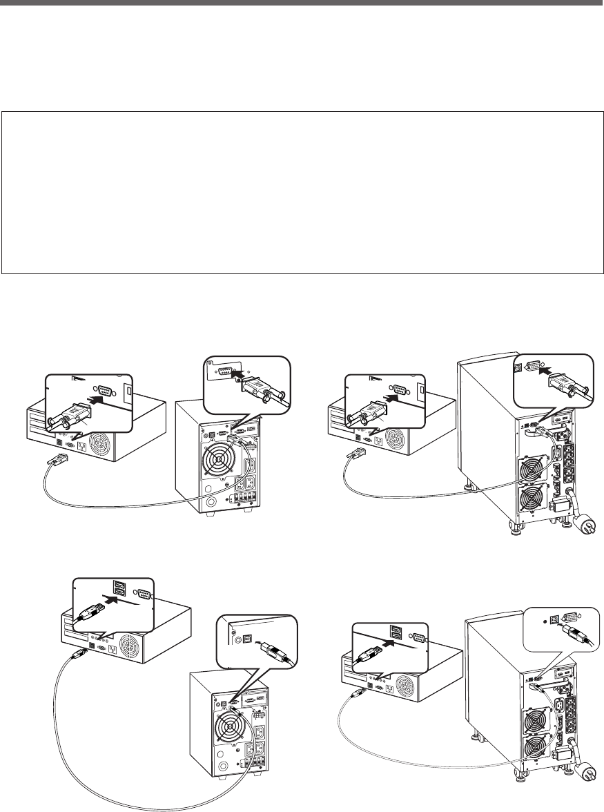
67
7.Using the UPS monitoring software and contact signal
1. Connect the UPS to a computer.
Cable: Included connection cable (RS-232C or USB)
* The RS232C and USB cannot be used at the same time.
BU1002SW
信
号
カ
ー
ド
増
設
RS232C
Connector
Connect to
RS-232C
terminal
Connect to RS-232C
port on PC
Included connection cable(RS-232C)
Connector
Connect to
RS-232C
connector on UPS
<RS-232C>
<USB>
BU1002SW
Connector
Connect to
USB
terminal
Connect to USB
port on PC
Included connection cable(USB)
Connector
Connect to
USB Port
on UPS
7-1 When using the included UPS monitoring
software to perform auto shutdown
Connector
Connect to
USB
terminal
Connect to USB
port on PC
Included connection cable(USB)
Connector
Connect to
USB Port
on UPS
BU3002SW
BU3002SW
Connector
Connect to
RS-232C
terminal
Connect to RS-232C
port on PC
Included connection cable(RS-232C)
Connector
Connect to
RS-232C
connector on UPS
● When using PowerAct Pro “UPS monitoring software for Windows/Linux”
"PowerAct Pro" UPS monitoring software
The included "PowerAct Pro" UPS monitoring software allows you to automatically save files and perform
shutdown processing of your PC when a power failure occurs.(It is possible to shut down multiple com-
puters on the network.)
Also, you can perform desired operation by setting the automatic start/stop of the UPS based on the
schedule setting.
*The time between the occurrence of a power failure and the shutdown of your PC must be within the
backup time measured in "5-1 How to measure backup time" on page 51.
For more information, refer to the Instruction Manual and online help of the UPS monitoring software.
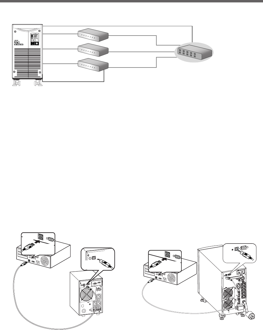
68
7.Using the UPS monitoring software and contact signal
2. Install the included UPS monitoring software on each computers.
Software to install: PowerAct Pro
How to install: Refer to the separate “UPS monitoring software installation guide”.
* When connecting 2 or more computers to the UPS
Switching hub
UPS
PC server 3
Power cable
Power cable
Power cable
LAN connection
Remote connection
The included connection cable (RS-232C or USB)
Power cable
PC server 2
PC server 1
Network
-
バッテリ
交換
バッテリ
増設
ブザー停止/テスト
電源出力
バイパス
運転
● When using UPS Power Manager “UPS monitoring software for Mac”
1. Connect the UPS to a computer.
Cable: Included USB communication cable
* Only 1 computer can be connected to the UPS
2. Install the included UPS monitoring software on the computer.
Software to install: UPS Power Manager
How to install: Refer to the separate “UPS monitoring software quick installation guide”.
<USB>
BU1002SW
Connector
Connect to
USB
terminal
Connect to USB
port on PC
Included connection cable(USB)
Connector
Connect to
USB Port
on UPS
Connector
Connect to
USB
terminal
Connect to USB
port on PC
Included connection cable(USB)
Connector
Connect to
USB Port
on UPS
BU3002SW

69
7.Using the UPS monitoring software and contact signal
Scheduled operation using the UPS monitoring software
●When performing scheduled operation in which the UPS is stopped and a device such as a breaker is
used to stop the UPS at the same time that commercial power stops, specify a period of no more than 3
months for the start of the next operation.
If you specify a period longer than 3 months, the internal timer is reset and the scheduled operation does
not start.
Note that this period reduces to approximately half when the battery is dead.
If a period of 3 months is exceeded, you start operation by supplying commercial power and pressing
the Start Switch. However, if the battery is dead, you may not be able to start operation. In this case,
replace the battery according to "6-2 Replacing the battery" on page 54.
Start of operation in scheduled operation using the UPS monitoring software
●To manually start up this unit after it has been stopped by a scheduled operation, turn OFF the power
switch and turn it back ON again.
To stop the unit when it is in operation, turn OFF the power switch.
Auto restart after OS closing processing using the UPS monitoring software
●When a power failure occurs, certain PCs (*1) automatically restart immediately after the OS is shut down
by auto shutdown.
In this case, the UPS stops during or after the restart of the PC, which may damage files and the hard
disk. You can avoid this phenomenon by disabling POWER MANAGEMENT in the BIOS settings of the
PC.
*1) Certain PC: It is known that this phenomenon occurs for MICRON's Millennia Mme.
Precautions when “setting the UPS to stop automatically” after OS shutdown
●If, after a power failure occurs, the power is restored while auto shutdown processing is being performed,
UPS output stops once after the set time elapses. After shutdown processing is complete, do not turn
ON the computer until the UPS has finished restarting.
Explanation
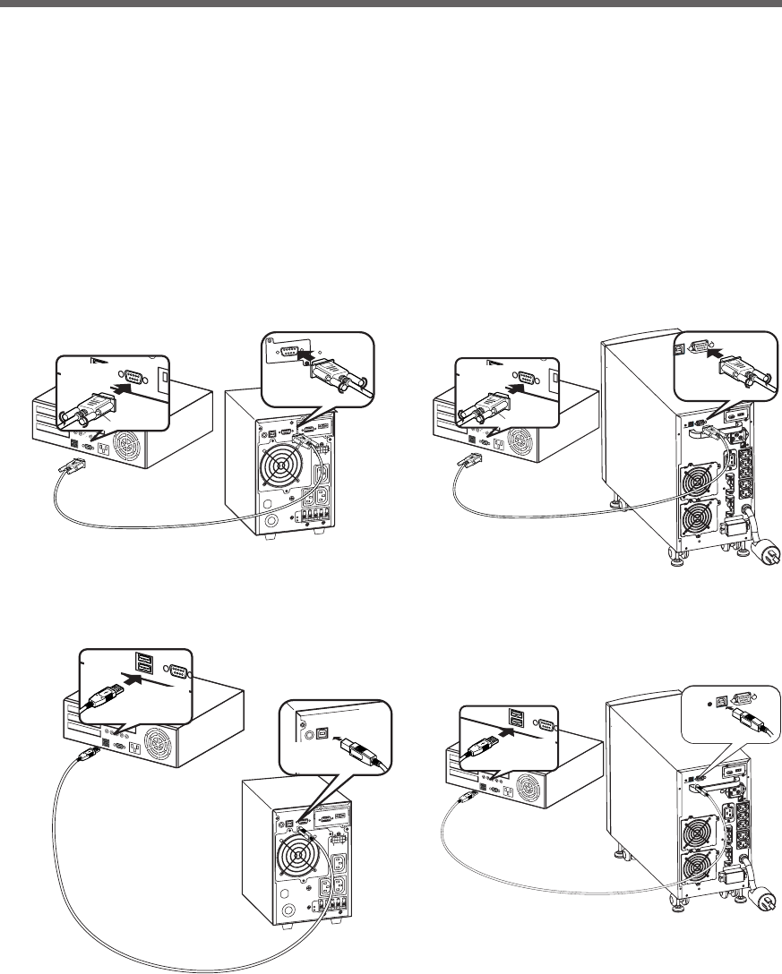
70
7.Using the UPS monitoring software and contact signal
7-2 When performing auto-save functions using
the UPS service in Windows Server 2003/XP/
2000 + UPS service driver
When using the included "UPS service driver", the OS standard UPS service in Windows Server 2003/XP/2000
can be used. When there is a power failure, files can automatically be saved and the computer can be shut
down.
1. Connect the UPS to a computer.
* Only 1 computer can be connected to the UPS
Cable: Included connection cable (RS-232C or USB)
* The RS232C cable and USB cable cannot be used at the same time.
BU1002SW
信
号
カ
ー
ド
増
設
RS232C
Connector
Connect to
RS-232C
terminal
Connect to RS-232C
port on PC
Included connection cable(RS-232C)
Connector
Connect to
RS-232C
connector on UPS
<RS-232C>
<USB>
BU1002SW
Connector
Connect to
USB
terminal
Connect to USB
port on PC
Included connection cable(USB)
Connector
Connect to
USB Port
on UPS
BU3002SW
Connector
Connect to
RS-232C
terminal
Connect to RS-232C
port on PC
Included connection cable(RS-232C)
Connector
Connect to
RS-232C
connector on UPS
Connector
Connect to
USB
terminal
Connect to USB
port on PC
Included connection cable(USB)
Connector
Connect to
USB Port
on UPS
BU3002SW
2. Install the included "UPS service driver" on the computer.
Software to install: UPS service driver
How to install: Refer to the separate "UPS monitoring software installation guide".
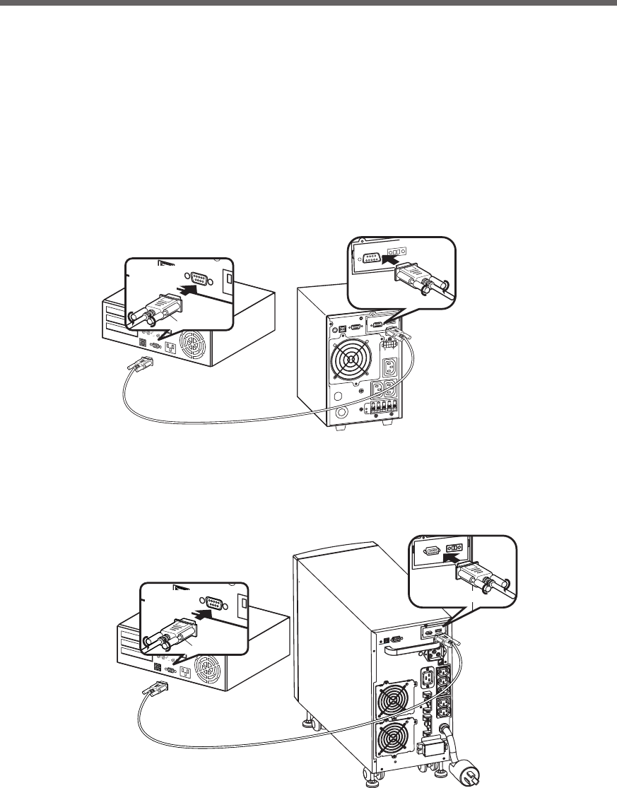
71
7.Using the UPS monitoring software and contact signal
7-3 When performing auto-save functions using
the standard UPS service in Windows Server
2003/XP/2000/NT
When using in combination with the BUC26 cable (sold separately), the OS standard UPS service in Windows
Server 2003/XP/2000/NT can be used. When there is a power failure, the computer can be shut down.
1. Connect the UPS to a computer.
Cable: Connection cable (BUC26), sold separately
* Only 1 computer can be connected to the UPS
Connector
Connect to
RS-232C
terminal
Connect to RS-232C
port on PC
BU1002SW
Connection cable (BUC26)
Connector
Connect to
contact signal
connector on UPS
BU3002SW
Connector
Connect to
RS-232C
terminal
Connect to RS-232C
port on PC
Connection cable (BUC26)
Connector
Connect to
contact signal
connector on UPS
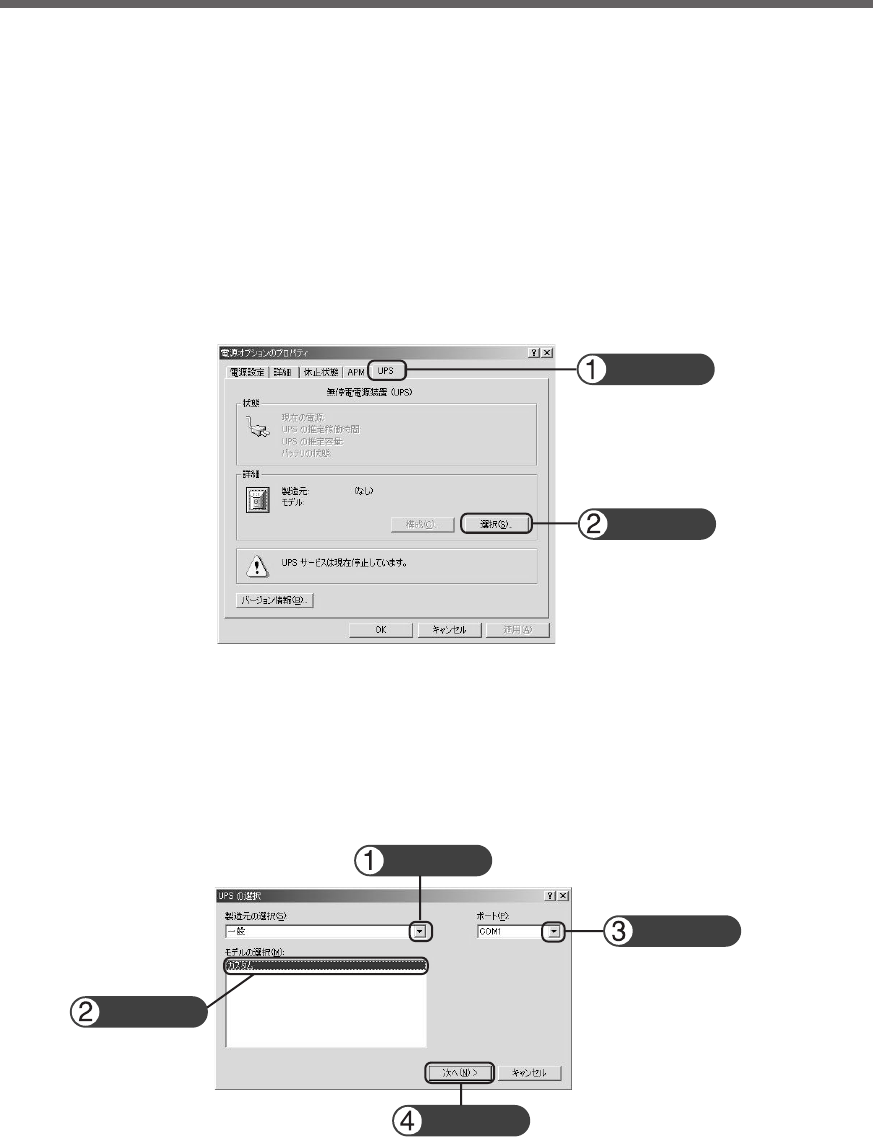
72
7.Using the UPS monitoring software and contact signal
2. Perform UPS service setup.
You need to make Windows settings in order to perform auto shutdown. There is no need to install software.
<When using the Windows Server 2003/XP/2000 standard UPS service>
Start up the computer after connecting it with the UPS.
Perform "Log on to Windows" as the Administrator.
After logging on, follow the instructions below to set up the UPS service.
● How to set up UPS service (shut down Windows when low battery level is detected)
1) Double-click the "Power supply options" icon in "Control Panels".
2) Click the "UPS" tab in the "Power supply options" window.
Click the "Select (S)" button.
3) Click the button on the right of the "Select manufacturer (S)" window, and select "General" from the list.
Click on "Custom" in the "Select model (M)" window.
Click the button on the right of the "Port (P)" window, and select from the list the port that the UPS is
connected to. (In the example screen below, the UPS is connected to COM1.)
Click the "Next (N)" button.
Click
Click
Click
Click
Click
Click
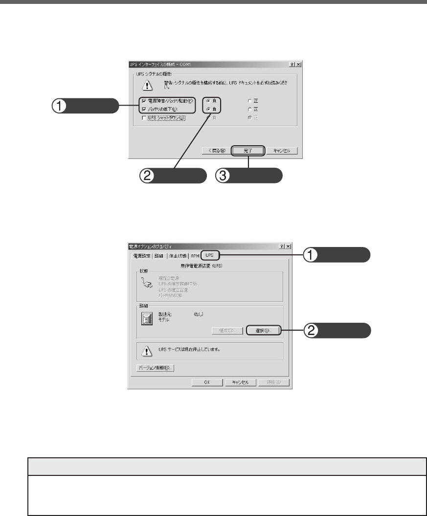
73
7.Using the UPS monitoring software and contact signal
4) In the "UPS signal polarity" box, click on the boxes to the right of "Power supply failure/battery drive (P)"
and "Low battery (L)" signals to insert check marks.
Set the polarity for each signal to "Negative". Click the "End" button.
5) Click the "OK" button in the "Power supply options" window.
Setup is complete.
When a power failure occurs, Windows shutdown starts once the Low battery level signal is detected.
If the power is restored before the Low battery level signal is detected, Windows shutdown does not
start and the normal monitoring state is restored.
Recycling and Discarding the Battery
In the Windows Server 2003/XP/2000 UPS service, there is no function to stop the UPS. After Win-
dows is shut down, manually turn OFF the unit's power switch.
Stopping the UPS
Click
Check
Check
Click
Click
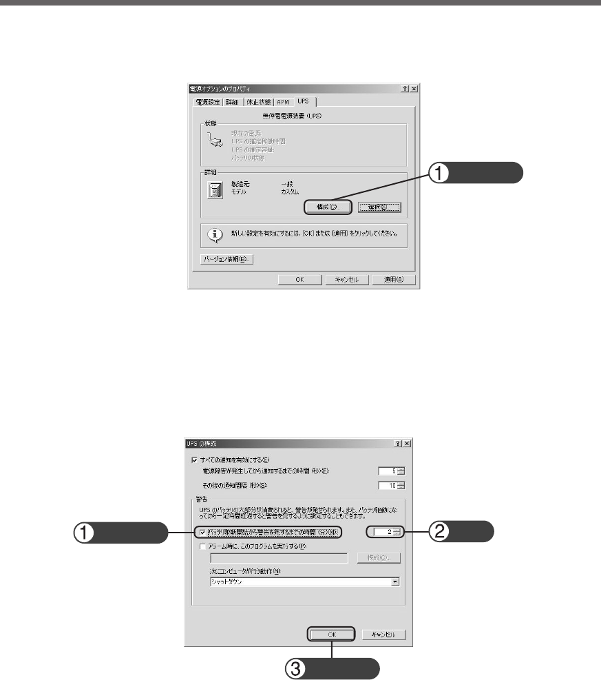
74
7.Using the UPS monitoring software and contact signal
● How to set up UPS service (set the time to shut down Windows)
1) After performing the setup described in the previous section, click the "Configure (C)" button in the
"Power supply options" window.
2) In the "Warning" box, place a check mark in the box to the left of "Time from when battery drive starts
until warning is issued (M)" by clicking on it.
In the window to the right, set the amount of time to wait before starting Windows shutdown after a
power failure occurs. (Setting range: 2 to 720 minutes)
Click the "OK" button.
Click
Check Set
Click
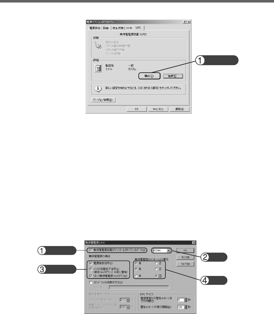
75
7.Using the UPS monitoring software and contact signal
3) Click the "OK" button in the "Power supply options" window.
Setup is complete.
When a power failure occurs, Windows shutdown starts once the set time is exceeded or the low battery
voltage signal is detected.
If the power is restored before the set time is exceeded, Windows shutdown does not start and the
normal monitoring state is restored.
<When using the Windows NT standard UPS service>
● How to set up UPS service
1) Double-click the "UPS" icon in "Control Panels".
2) Insert a check mark in the checkbox to the right of "Port where UPS is installed (U)..." by clicking on it.
In the setting field, select the number of the serial port (COM1 to 4) the unit is connected to.
3) To shut down Windows when a low battery is detected, click on the checkboxes to the left of "Power
failure signal (P)" , "Low battery level signal (L)" and "Remote uninterruptible power source shutdown
signal (R)" to insert check marks.
Set each signal interface voltage setting as shown below.
- Power failure signal (P) ... Negative
- Low battery signal (L) ... Negative
- Remote uninterruptible power source shutdown ... Positive
Click
Check
Check
Set
Set
<Setting to detect low battery singal and shut down Windows>
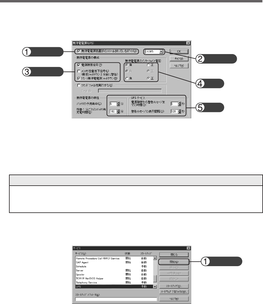
76
7.Using the UPS monitoring software and contact signal
Please note that in the case of incorrect interface voltage signal settings, Windows NT will not receive
the signal from the UPS and the UPS will not stop when there is a power failure.
Failure to put check marks in the boxes will lead to the same result.
Note
4) To set the time to shut down Windows, click on the checkboxes to the left of “Power failure signal (P)”
and “Remote uninterruptible power source shutdown signal (R)” to insert check marks.
Check
Check
Check
Set
Set
Set each signal interface voltage setting as shown below.
- Power failure signal (P) ... Negative
- Remote uninterruptible power source shutdown ... Positive
Set the attributes for the uninterruptible power source and the time for each UPS service item.
<Setting to detect low battery singal and shut down Windows after the set delay period>
5) After the settings are made, double-click the "Service" icon in "Control Panels".
6) Select the UPS service and click the "Start" button.
By starting the alerter service, messenger service, and event log service in advance, the UPS service
sends warning messages to the user and records a history of events such as power failures when they
occur.
When a power failure occurs, Windows shutdown is performed once the Low battery level signal is
detected. If the power is restored before the Low battery level signal is detected, Windows shutdown is
not performed and the normal monitoring state is restored.
Click
77
7.Using the UPS monitoring software and contact signal
7-4 Contact signal
Contact Signal
You can develop your unique system based on the following specifications to automate the process at a power
failure. You can perform power-failure processing by allowing the system to detect the backup signal and also
perform system shutdown processing by allowing the system to detect the Low battery level signal. Also, by
inputting the backup stop signal from the system, you can stop the UPS with a sufficient battery level to prepare
for the next occurrence of a power failure.
1. Signal output
The UPS has 4 kinds of output signals. The output circuit consists of an open collector circuit using a photo
coupler (a kind of electronic switch).
●Backup Signal output: BU
BU stays ON during a power failure.
●Low battery level signal output: BL
Goes ON when the battery becomes weak during the
Battery Mode.
●Trouble Signal output: TR
Goes ON when an internal failure of the UPS occurs.
●Battery Replacement Signal output (WB)
Goes ON when the test determines that battery
replacement is necessary due to deterioration.
BL-COM ON when the battery is low
TR-COM ON when a power failure occurs
WB-COM
ON when battery deterioration is detected
BU-COM ON when a power failure occurs
2. Signal input
● Input of the UPS Stop Signal (BS)
Stops the output of the UPS after the time period specified by the “power output stop delay time setting”
has elapsed.
(1) When the "BS signal valid range setting" (setting switch 7 ) is set to OFF:
You can stop the output of the UPS by inputting the voltage signal (HIGH) that lasts at least 10 seconds
from the outside.
(2) When the "BS signal valid range setting" (setting switch 7 ) is set to ON:
You can stop power output by inputting the voltage signal (HIGH) that lasts at least 0.01 second (10
ms) from the outside that is accepted only during backup.
See also
"4-4 Changing the setting of the functions" "2. UPS operation mode settings" ➛ Page 42, 47
BS-COM UPS stops
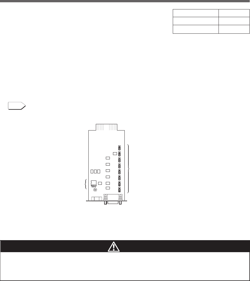
78
7.Using the UPS monitoring software and contact signal
● Remote ON/OFF Signal
Remote ON/OFF signals can be used to start and stop
the UPS, by using either an externally connected con-
tact or the ON/OFF status of the open collector circuit. To
use this function, turn on the Power Switch of the UPS.
(Note: When there is no AC power supply, it is not pos-
sible to start up UPS by the remote ON/OFF signals even
though cold start is set ON.)
Connection terminals are at contact signal connector pins
6 ,7 and the remote ON/OFF connector.
3. Items that can be set using the contact signal card
Please make a cable to connect to the system by yourself.
See also
"8. Example of the use of the Contact Signal circuit" ➛ Page 81
■Setting the switches
Jumper setting
s
(8 digits)
DIP switches
(3 digits)
External contact Operate
Open Start
Close Stop
Caution
After changing the setting switch, disconnect the AC input plug, wait until the
status indicator is completely OFF, and then reinsert the AC input plug.
● The setting switch changes do not become valid until the AC input plug is reinserted.
By using the switches of contact signal card, set the item below.
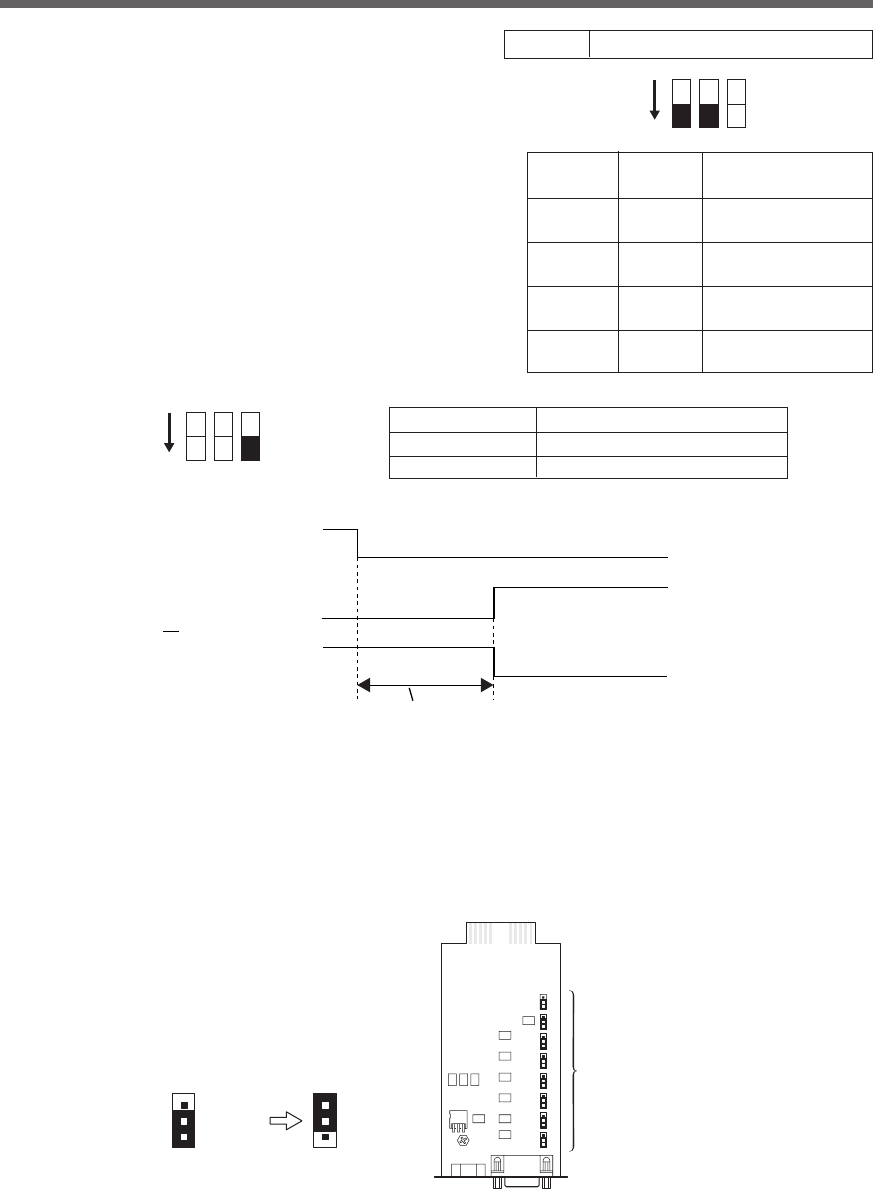
79
7.Using the UPS monitoring software and contact signal
SC05/06
SC07
SC05/06
Jumper settings
(8)
<Before change> <After change>
SC07
●Output delay time setting for backup signal output (BU)
Continues during a power failure, and turns ON (OFF).
By setting the contact signal card’s setting switch as
shown in the table on the right, the length of time from
when the power failure occurs until the power failure signal
is output can be delayed between 0 and 3 minutes.
The power failure signal is not output if the power supply
error is resolved within the set delay time.
●BU/BL signal reverse output setting
BU and BL signals are output in reverse.
BU-COM ON when there is a power failure
ON 1 2 3
Setting Setting Delay time
switch 1 switch 2 setting
OFF OFF 0 second
(factory setting)
ON OFF Signal output after
30 seconds
OFF ON Signal output after
60 seconds
ON ON Signal output after
180 seconds
AC input ON
OFF
ON
OFF
ON
OFF
BU signal
((setting switch 3:
OFF (normal output))
BU signal
((setting switch 3:
ON (reverse output))
Backup signal output (BU) delay time setting (setting switches 1, 2)
ON 1 2 3
Setting switch 3 Backup signal output (BU)
OFF
Normal output (factory setting)
ON Reverse output
■Jumper settings
By making jumper settings, the contact signal card SC05/06 connector pin assignments can be changed.
Turn over the contact signal card, and change all (8) of the jumper settings to "SC05/06".
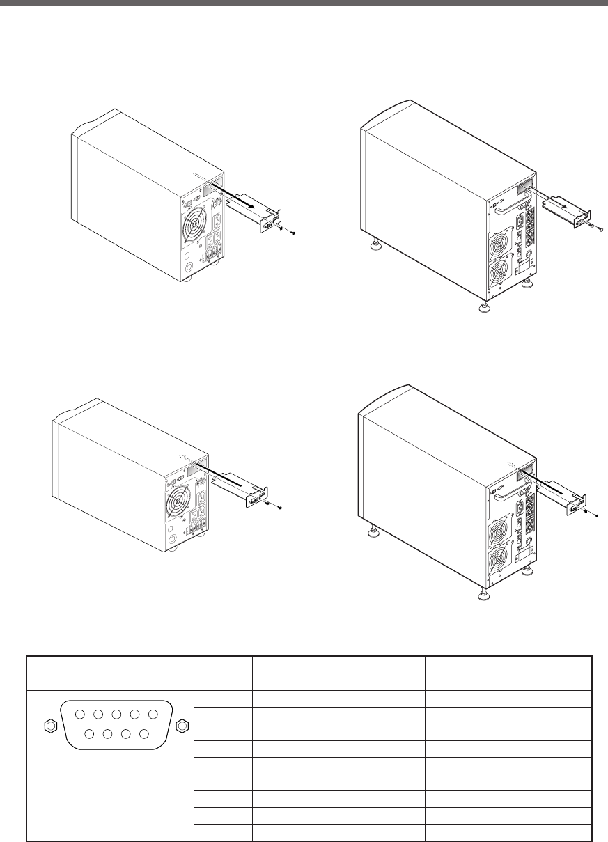
80
7.Using the UPS monitoring software and contact signal
4. Contact Signal Connector (female DSUB9P)
5 4 3 2 1
9 8 7 6
Front view
Screw size: inch screw
#4-40 UNC
Pin assignment
Pin number
For jumper setting “SC07” For jumper setting “SC05/06”
* Factory settings
1Battery LOW signal output (BL) NC
2Trouble signal output (TR) Backup signal output (BU)
3Backup stop signal input (BS)
Backup reverse signal output (BU)
4NC COMMON (COM)
5COMMON (COM) Battery Low Signal output (BL)
6Remote ON/OFF input (–) Backup stop signal input (BS)
7Remote ON/OFF input (+) Remote ON/OFF input (–)
8Backup signal output (BU) Trouble Signal output (TR)
9
Deteriorated battery signal output (WB)
Remote ON/OFF input (+)
BU1002SW
BU3002SW
BU1002SW
BU3002SW
■Insert/ removal method of contact signal card
(1) Turn OFF the power switch, remove the top and bottom screws (2 screws) of the contact signal connector
on the back of the unit, and carefully remove the contact signal card.
(2) After changing the settings, carefully reinsert the contact signal card and securely tighten the 2 screws.
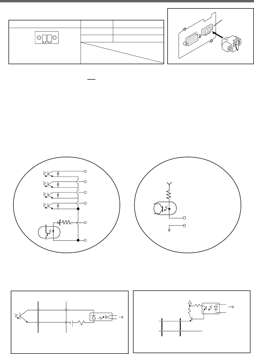
81
7.Using the UPS monitoring software and contact signal
6. Contact Signal ratings
●Signal output (BL, TR, BU, WB, BU) ●UPS Stop Signal input (BS)
Photo coupler ratings Input voltage HIGH(ON) 5 to 12 VDC
Appliable voltage: 35 VDC or less LOW(OFF) 0.7 VDC or less
Maximum current: 20 mA
●Remote ON/OFF
Voltage between terminals: 5 VDC
Current when closed: max.10 mA
7. Contact Signal circuit inside the UPS
5. Remote ON/OFF connector
Front view
Screw size: Inch screw
#4-40 UNC
Pin assignment Pin number Signal name
1Remote ON/OFF (+)
2 Remote ON/OFF (-)
1
2
8. Example of the use of the Contact Signal circuit
●Example of BU signal output circuit and
the connected circuit
●Example of BS signal input circuit and the
connected circuit
COM
UPS side
BU
12V1K
TLP627
To port on P
C
System side
Connecting cable
(
twisted or shielded
)
BL
TR
BU
WB
BS
COM
2.4V 560Ω
Remote ON/OFF (+)
Remote ON/OFF (-)
5V
10kΩ
COM
UPS side GND
System side
Connecting cable
(twisted or shielded)
BS
12V 1K
1.2K
TLP521
To port on PC
Connect the included
remote ON/OFF connector
Connector
82
7.Using the UPS monitoring software and contact signal
●Remote ON/OFF circuit
UPS side
remote ON/OFF(+)
remote ON/OFF(-)
Example of
remote ON/OFF
Notes
●When connecting a device such as a relay that generates counter electromotive force to the signal
output circuit, connect diodes that prevent counter electromotive force to both ends of the relay.
Explanation
●When power is restored after the unit stopped automatically during a power failure, the unit
automatically restarts and supplies power. If you do not want to start the connected devices, turn
OFF their switches or set the auto startup setting after recovery from power failure (setting switch
2) to ON(Auto startup is not performed). (See page 43.)
9. Precautions and notes for the use of the Contact Signal
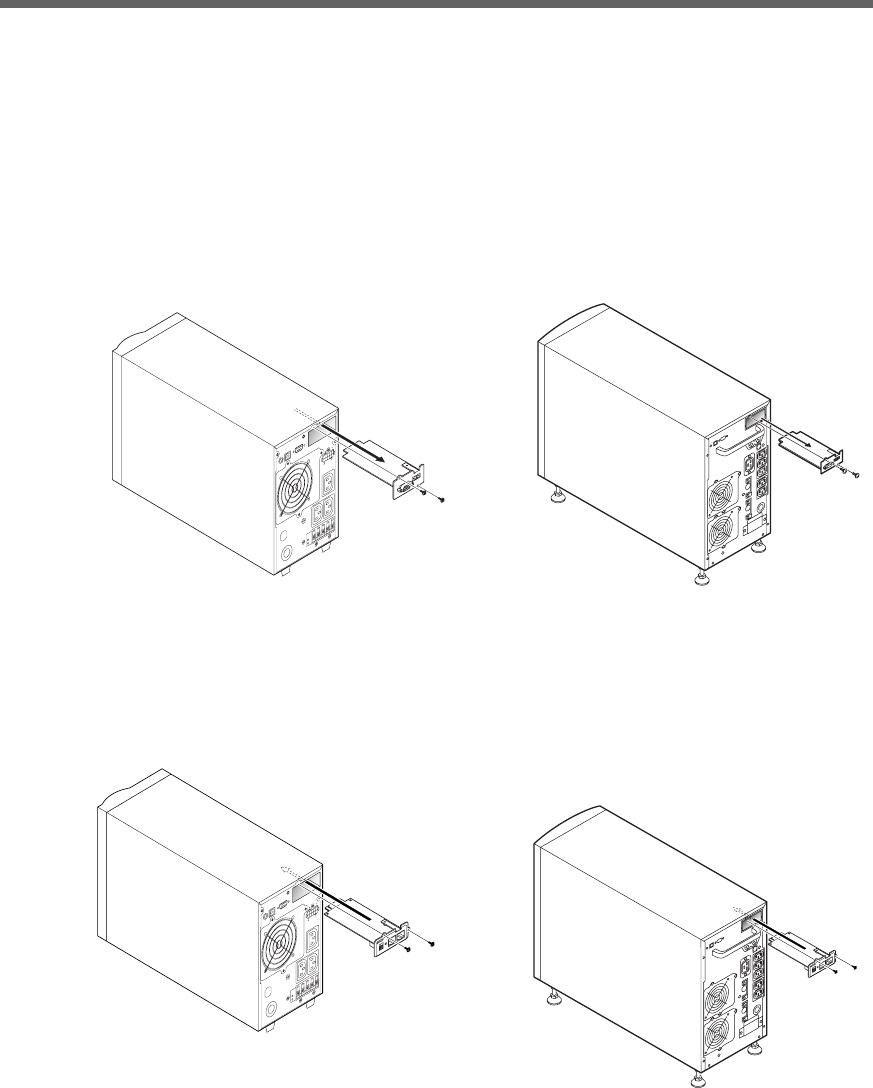
83
8.Using an SNMP/Web card
8. Using an SNMP/Web card
8-1 Adding an SNMP/Web card
An SNMP/Web card can be loaded into the card slot on the back of the unit. Remove the contact signal card
that the unit came equipped with, and plug the SNMP/Web card in its place. Store the removed contact signal
card in a safe place.
• SNMP/Web card (model number: SC20G), sold separately
(1) Remove the 2 screws, and carefully pull out the contact signal card.
(2) Carefully insert the SNMP/Web card (model number: SC20G), and securely tighten the 2 screws.
* Replace with BU50SW/BU75SW/BU100SW/BU150SW/BU1002SW/BU3002SW brackets.
BU1002SW
BU1002SW
BU3002SW
BU3002SW

84
8.Using an SNMP/Web card
For more details, refer to the instruction manual included with the SNMP/Web card.
The most recent firmware can be downloaded from our homepage(http://www.omron.co.jp/ped-j/download/
sc20/sc20.htm).
8-2 SNMP/Web card outline
■ Description (features)
•Direct connection between UPS and network
Inserting an SNMP/Web card (SC20G) into the UPS enables a LAN connection, allowing the UPS to be
controlled via computers with no serial port.
•Remote UPS management
Using a commercially available SNMP manager or web browser, you can control the UPS via a
computer connected to the network.
•Possible to make function settings for the UPS and SNMP/Web card via a computer on the network UPS
and SNMP/Web card (SC20G) parameter settings can be made via any SNMP management station or
internet browser. (Functions that act as an SNMP agent can make settings via Telnet and serial connec-
tion.)
•Enhanced security functions
For HTTP and SNMP connections, access can be controlled for each IP.
•Coordinated shutdown
Multiple UPS can coordinate with each other to perform shutdown.
•Log function
* The UPS power status, battery status, etc. can be stored in the built-in flash memory.
* Compatible with SYSLOG.
•Auto shutdown function
Shutdown is automatically performed when there is a power supply error or when a shutdown has been
scheduled. Scheduled operations (auto startup and auto shutdown) can be performed over the net-
work.
•Equipped with UPS standard MIB (RFC1628) and proprietary MIB (swc mib)
•Using JAVA applet to monitor the power supply status
The power supply status can be visually checked on a graph display.
■ Specifications
LAN port 10/100 Mbit
Network protocol SNMP, HTTP, APR, RARP, TFTP, ICMP
Other communication route Serial connection: asynchronous method (setting only)
Number of controllable computers 32 max. (including slave UPS when coordinated shutdown is enabled)
Support MIB UPSMIB (RFC1628)
OMRON MIB
Other Equipped with real-time lock
Windows NT 4.0, Windows 2000, Windows XP, Windows Server 2003
Red Hat Linux 7.2/7.3/8.0
Shutdown software-compatible OS Red Hat Enterprise Linux AS/ES/WS (Red Hat Linux Advanced Server
2.1)
Max OS X v10.3*/Server 10.39 (*1)
Max OS X v10.4*/Server 10.4 (*1)
(*1) Compatible only with Macintosh computers equipped with PowerPC CPU.
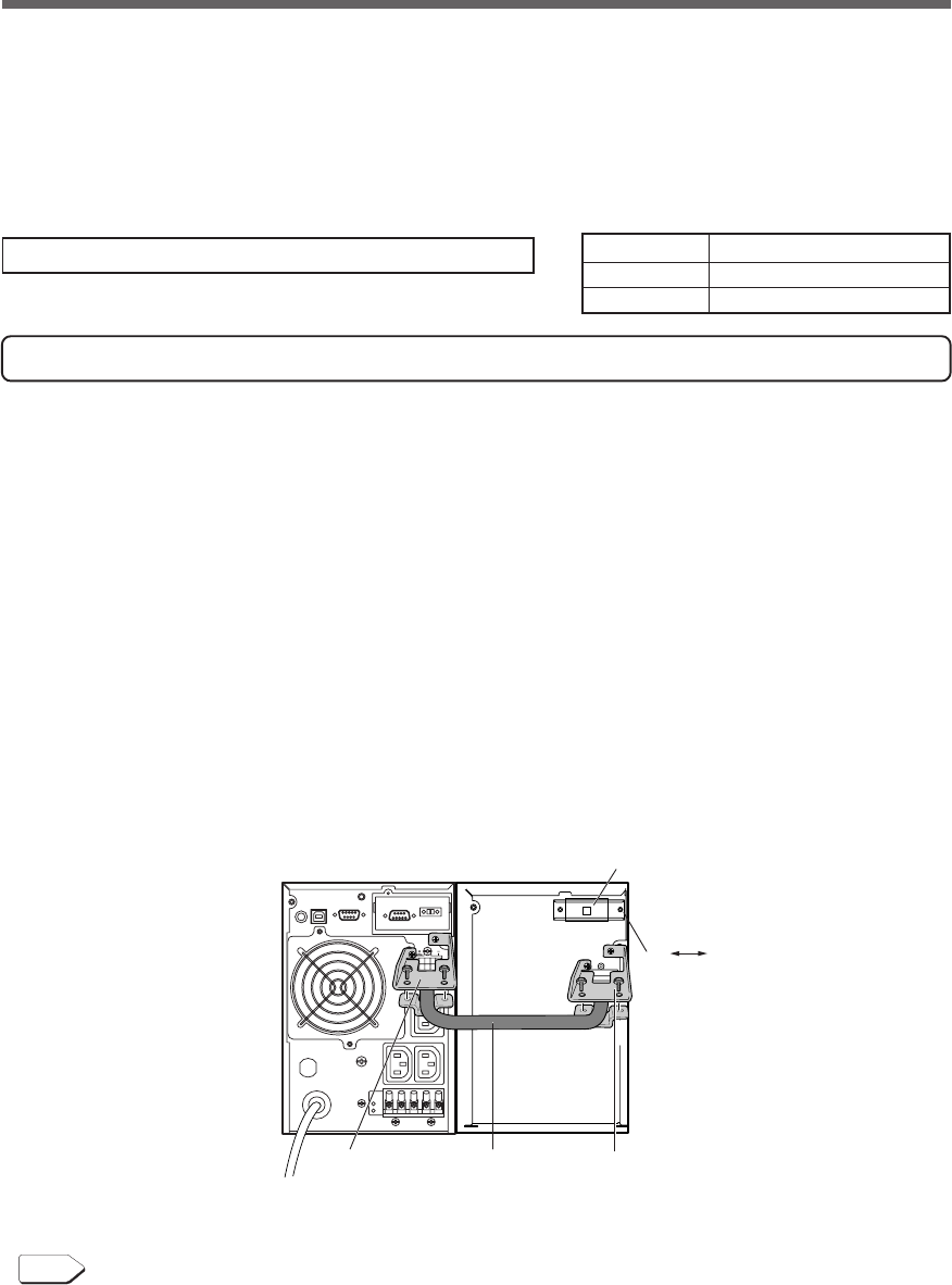
85
9.Extending the backup time
9. Extending the backup time
9-1 Connecting an additional battery unit
You can extend the backup time by connecting an additional optional battery unit to the UPS.
When an additional battery unit is connected, the charging time is 24 hours.
Adding BUM100S to the BU1002SW
For the BUM100S, the included battery connection cable is provided with cable clamps attached. Connect the
battery connection cable according to the instructions below.
(1) Loosen the screws and remove the battery connector covers on the rear side of the unit and battery unit.
Use the removed screws to attach the cable clamps.
(2) Connect the battery connection cable to the battery connectors on the rear side of the unit and the battery
unit. To simplify the operation, do not yet tighten the screws that hold the battery connection cable on the
cable clamp.
(3) Use screws to attach the cable clamps to the rear side of the unit and the battery unit (2 screws each).
(4) Tighten the screws that hold the battery connection cable on the cable clamps.
(5) Turn ON the overcurrent protection switch on the back of the battery unit.
(6) Connect the AC input plug of the unit to a wall outlet. The additional battery lamp on the unit's operation
panel turns ON.
You can connect only one additional battery unit.
For information on backup time, see the backup time table in ”5-2 Estimated backup time”.
➛ Page 51
See also
BU1002SW BUM100S
ON OFF
Overcurrent protection
switch
Cable clampCable clamp
Battery connection
cable
UPS Additional battery unit
BU1002SW BUM100S
BU3002SW BUM300S
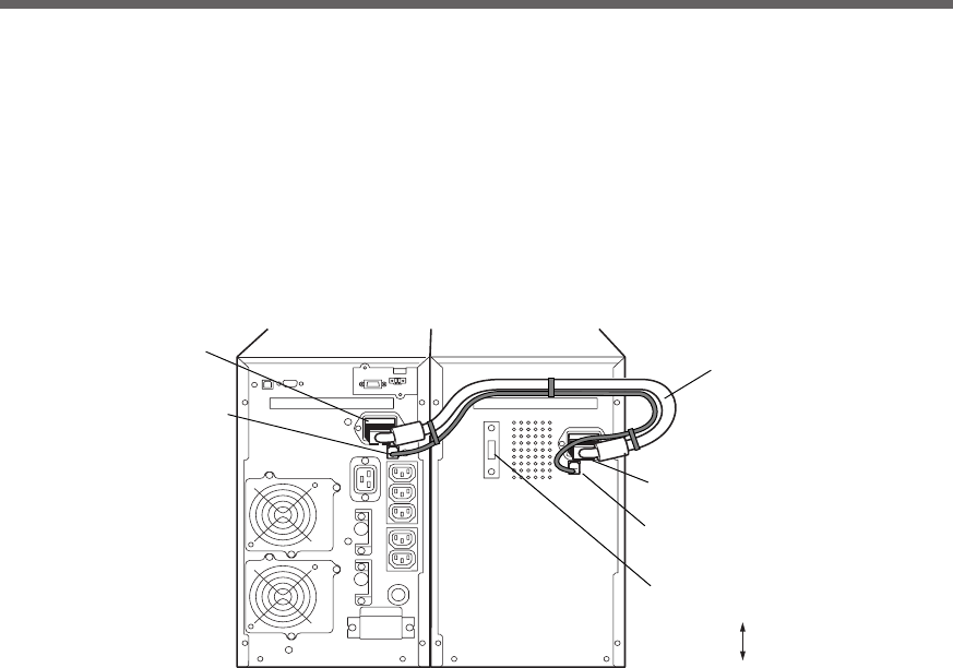
86
9.Extending the backup time
BU3002SW BUM300S
Additional battery
signal connection
Additional battery
connection
Additional battery
signal connection
Additional battery
connection
ON
OFF
Overcurrent protection
switch
Battery connection
cable
Adding BUM300S to the BU3002SW
(1) Loosen the screws and remove the battery connector covers on the rear side of the unit and battery unit.
(2) Connect the battery connection cable to the battery connectors on the rear side of the unit and the battery
unit. Connect the battery connection cable to the additional battery signal connector also.
(3) Turn ON the overcurrent protection switch on the back of the battery unit. Connect the AC input plug of the
unit to a wall outlet. The additional battery lamp on the unit's operation panel turns ON.

87
10. Troubleshooting
UPS does not operate.
The LED display does not
light up, even though the AC
input plug is connected to a
wall outlet (commercial
power) and the power switch
is ON.
Backup is not possible.
The computer stops when a
power failure occurs.
Backup is performed too
frequently.
Frequent switching is
performed although a power
failure does not occur.
You hear the sound of
switching.
Does not turn ON when
power switch is pressed.
The display is abnormal.
●The display is unstable.
●White lines occur.
●Noise increases.
The battery replacement
lamp blinks and the beeper
sounds at 2-second
intervals.
The status indicator shows
“”, and the beeper sounds
at 0.5-second intervals.
The status indicator blinks
“”, and the beeper
sounds continuously.
10. Troubleshooting
Perform the checks shown below if the unit is operating abnormally.
If the unit continues to operate abnormally, please contact our peripheral device customer support center at
_____.
Problem
1. Check that the AC Input Plug is connected to the commercial power securely.
2. The AC Input Overcurrent Protection is working.
(If the black button has popped up, there are probably too many connected devices or
there is a short in the connected devices.) Disconnect all of the connected devices,
push in the the black AC input overcurrent protection button and turn ON the Power
Switch of the UPS again. If the status indicator does not display normally, there is a
problem with the UPS. (See "Interpreting beeps and displays" on page 39.)
Is charging insufficient?
Perform the test after charging the battery for at least 8 hours. (When an additional battery
is connected, the charging time is 24 hours.)
(You can charge the battery by connecting the AC input plug of the UPS to a wall outlet
(commercial power).)
Variations (decrease) in the input power occur frequently. Or, noise is included that
significantly distorts the voltage waveform of the input power.
●Change the wall outlet (commercial power) to which you connect the UPS. Try connecting
to a wall outlet (commercial power) away from equipment that consumes large power.
●This problem may occur also when you connect many devices to a plug strip or extension
cord connected to the UPS if it is a long or thin cable.
The unit does not start up when the input power supply voltage/frequency is abnormal.
(The status indicator displays “H-”, “-H”, “L-” or “-L”.) Check the voltage and frequency of
the input power supply.
See also
A. Specifications Input Allowable voltage range, frequency see Page 88
The probable cause is noise that occurs inside the UPS.
●Ground all devices connected to the UPS. Connect them to a wall outlet (commercial
power) for 3-pin plugs or connect their Grounding Terminal to the Grounding Terminal of
a wall outlet.
●This problem may occur when power cords are long or placed closely or when the UPS
and devices to be backed up are placed closely. Rearrange them.
●If the UPS or devices connected to the UPS are contained in a metal rack, attempt to
ground the rack itself.
1) The auto battery test or self-diagnostic test determined that the battery is dead.
2) Did the overcurrent protection switch on the rear panel of the additional battery unit get
turned OFF when connecting an additional battery unit?
If it is not ON, the auto battery test may falsely detect a deteriorated battery.
There are too many connected devices. Reduce the number of connected devices until
“” is displayed on the status indicator.
The UPS stopped because too many devices were connected for 3 minutes or more, or
because 120% was exceeded.
Turn OFF all power to the unit and connected devices, and reduce the number of connected
devices. Then, turn the power to the unit and connected devices back ON and check
whether " " is displayed on the status indicator.
Check and remedy

88
Reference
References
A. Specifications
Frequency 50/60Hz ± 4Hz
Maximum current 7.4A 16A
Phase Single-phase, two-wire
Input plug shape NEMAL6-15P NEMAL6-20P
Input protection Reset-type overcurrent protection device
Input protection capacity 10A 20A
Output
Allowable connection capacity *1
1000VA/700W 3000VA/2100W
Voltage (effective value) *2
Peak voltage value 200V mode: AC282V ± 6% 220V mode: AC310V ± 6%
(In Commercial Power Mode)
230V mode:AC324V±6% 240V mode:AC338V±6%
Peak voltage value 200V mode:AC282V±6% 220V mode:AC310V+6%/-10%
(In Battery Mode) 230V mode:AC324V+6%/-10% 240V mode:AC338V+6%/-12%
Frequency 50/60Hz ± 1Hz
Phase Single-phase, two-wire
Output waveform
Sine wave
Waveform distortion rate 200V mode: 6% max. 220V mode: 10% max.
(Rectified load, at rated output)
230V mode: 10% max. 240V mode: 12% max.
Number of output receptacles IEC60320 C13 : 3 pcs. IEC60320 C19 : 1 pcs. C13 : 5 pcs.
Terminal block: 2 lines Terminal block: 2 lines
Power failure switching time Uninterrupted
Commercial direct shipment
(switching time)
4msec. max.
Backup time *3
Minimum 5 minutes
Battery Type Compact sealed lead battery
Sealed lead battery life expectancy
4 to 5 years (long operating life) *At ambient temperature of 20°C
Battery capacity (V/Ah) (x Quantity)
12V DC/ 7.2 Ah (x 3) 12V DC/ 9 Ah (x 6)
Charging time 8 hours *4
Environment
Operating ambient temperature
0 to 40°C (during operation)/ -15 to 50°C (during storage)
Operating ambient humidity
25 to 85%RH (during use)/10 to 90%RH (during storage)
Dimensions 145 x 395 x 224 (±1) mm *5 213 x 537 x 432 (±1) mm *6
Weight of unit
Approx. 15.5 kg Approx. 35 kg
Internal power
consumption (max.)
50W (100W max.) 55W (155W max.)
*7
Noise regulation
(compliance standard)
VCCI Class A
Safety standard compliance
UL/CE
Noise 50 dB max. 55 dB max.
BU1002SW BU3002SW Type
200V mode AC200V ± 3%
220V mode AC220V ± 3%
230V mode AC230V ± 3%
240V mode AC240V ± 3%
Method Operation method Full-time inverter supply method
Connectable devices
PC, display, and peripherals
Input Rated input voltage 200 to 240V ± 10%
Allowable voltage range AC145±4 to 276±4V (with 85% or less connection load)
AC170±4 to 276±4V (with 85% or more connection load)
*1: Make sure that both the VA value and the W value of the load capacity connected to the UPS are within the range specified here.
*2: Check the operation beforehand if the unit is used in any mode other than “200V AC mode”. In some cases, the maximum voltage
of output in Battery Mode may be lower than the maximum voltage in usual operation (commercial power supply).
*3: The backup times shown here are for when rated load is connected, at 20°C, and for initial characteristics.
*4: When an additional battery unit is connected, the charging time is 24 hours.
*5: The height includes the 13-mm height of the rubber feet.
*6: The height includes the 56mm height of the casters.
*7: 170W max when and additional battery unit is connected.
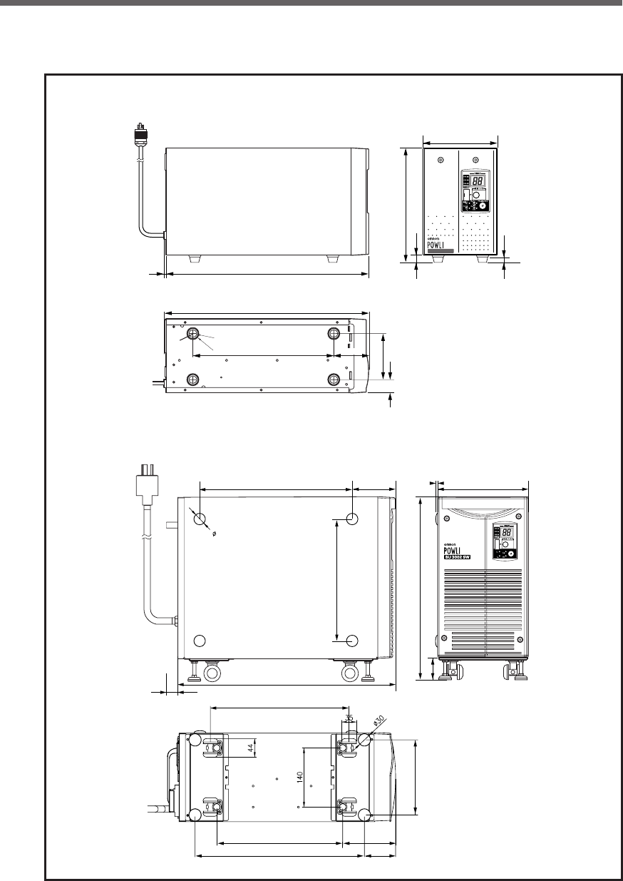
89
Reference
B. Dimensions
(Unit: mm / Tolerance: ± 1mm)
3955
91
26
402
278
224
13
10
64
BU1002SW
ø15
ø25
M4
Screw
Power cable (approx. 1.8 m)
145
21
-
バッテリ
交換
バッテリ
増設
ブザー停止/テスト
電源出力
バイパス
運転
509
329
402
299 117
66
28
432
56
178
286
213
3
99
360
(Unit: mm / Tolerance: ± 1mm)
Power cable (approx. 1.8 m)
•BU3002SW
•BU1002SW
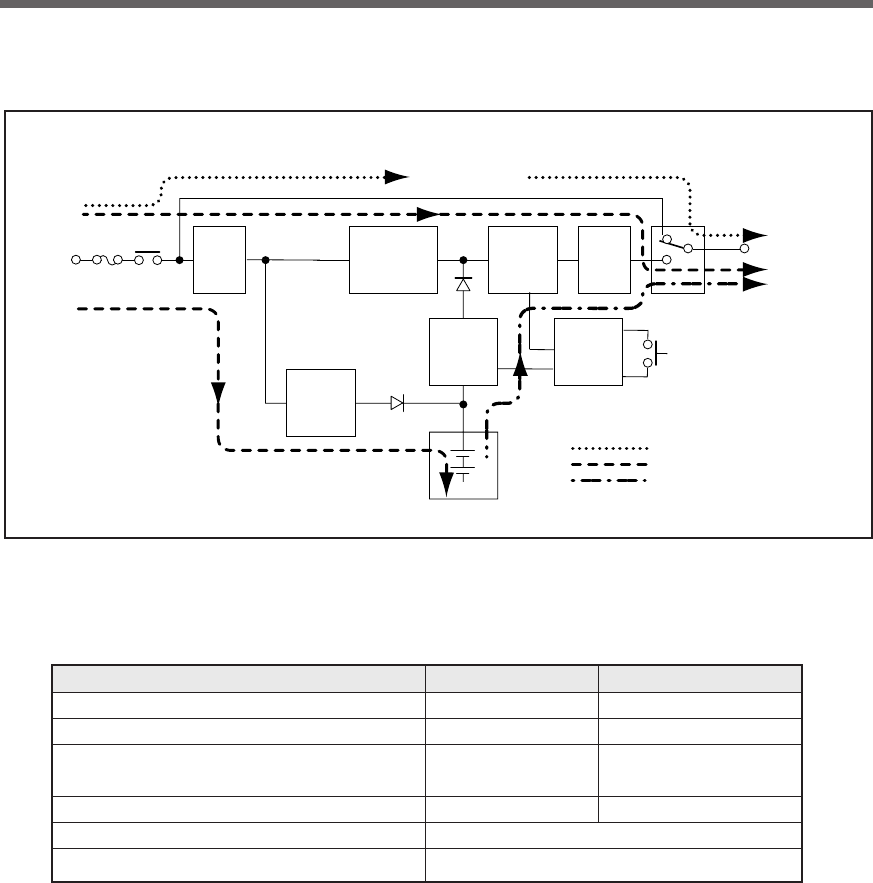
90
Reference
C. Circuit block diagram
Power supply
switch
At startup/capacity exceeded/error
During Line mode
During Battery mode
Commercial
power bypass
output
Noise
filter
200 to
240V AC
input
Power supply
relay
Input overcurrent
protection
Charging
circuit
Step-up
converter Control
circuit
Battery
Rectifier
(high power
factor
converter)
Inverter
(sine
wave)
Filter
Output
switching
Power
supply
output:
200/220/
230/240V AC
D. Related products
Description BU1002SW BU3002SW
Replacement battery pack BP100XS BP150XS (two required)
Additional battery unit BUM100S BUM300S
Replacement fan
BUF1002S for rear fan BUF1002S for rear fan
BUF3002S for front fan
Mounting bracket BUP100S BUP300S
SNMP/Web card SC20G
Connection cable for Windows UPS service BUC26

No part or whole of this manual may be reproduced without permission.
The contents of this manual are subject to change without notice.
OMRON Corporation K1L-D-06051B
