On Track Innovations 13560K915MCON VST/PST Controller User Manual
On Track Innovations Ltd VST/PST Controller Users Manual
UserManual.wiki
>
On Track Innovations
>
13560K915MCON User Manual
>
Users Manual
Contents
1.
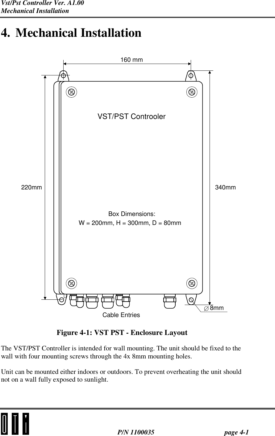
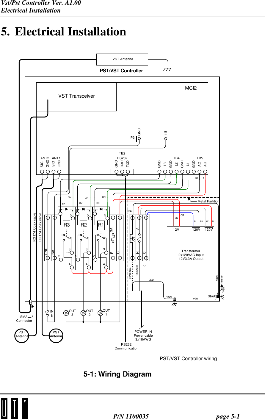
Users Manual
2.
Correctected Page to Users Manual
3.
Corrected Page to Users Manual
Users Manual
Navigation menu
Upload a User Manual
Namespaces
Wiki Guide
HTML
PDF
Info
Views
User Manual
Discussion / Help
Navigation