Ondas Networks FS-CP757787 FullMAX Cobalt-Plus User Manual Rev
Full Spectrum Inc. FullMAX Cobalt-Plus Rev
User Manual Rev

Full Spectrum Inc. | 687 N. Pastoria Avenue, Sunnyvale, CA 94085 | (888) 350-9994 | fullspectrumnet.com
FullMAX
Cobalt-Plus
Installation Manual
Version 1.2
June 2017
Warning: Never power on a FullMAX radio without a
load on the RF connector.

Page 2 of 13 January 2017
Copyright © 2017 Full Spectrum Inc. All rights reserved.
NOTE: This equipment has been tested and found to comply with the limits for a Class A digital device,
pursuant to part 15 of the FCC Rules. These limits are designed to provide reasonable protection against
harmful interference when the equipment is operated in a commercial environment. This equipment
generates, uses, and can radiate radio frequency energy and, if not installed and used in accordance
with the instruction manual, may cause harmful interference to radio communications. Operation of this
equipment in a residential area is likely to cause harmful interference in which case the user will be
required to correct the interference at his own expense.
NOTE: The user’s manual or instruction manual for an intentional or unintentional radiator shall caution
the user that changes or modifications not expressly approved by the party responsible for compliance
could void the user’s authority to operate the equipment. In cases where the manual is provided only in
a form other than paper, such as on a computer disk or over the Internet, the information required by
this section may be included in the manual in that alternative form, provided the user can reasonably be
expected to have the capability to access information in that form.
FCC Compliance Statement:
Note: This equipment has been tested and found to comply with the limits for a Class A digital device,
pursuant to part 15 of the FCC Rules. These limits are designed to provide reasonable protection against
harmful interference when the equipment is operated in a commercial environment. This equipment
generates, uses, and can radiate radio frequency energy and, if not installed and used in accordance with
the instruction manual, may cause harmful interference to radio communications.
Operation of this equipment in a residential area is likely to cause harmful interference in which case the
user will be required to correct the interference at his own expense.
Any changes or modifications not expressly approved by the party responsible for compliance could void
the user's authority to operate the equipment
This equipment complies with FCC radiation exposure limits set forth for an uncontrolled environment.
End users must follow the specific operating instructions for satisfying RF exposure compliance. This
transmitter must be at least 180 cm from the user and must not be co‐located or operating in
conjunction with any other antenna or transmitter.
The maximum allowable antenna gain for this device is 23.5 dBi and 9.5 dBi at 757.5 MHz and 787.5
MHz respectively

Page 3 of 13 January 2017
Table of Contents
1 System Overview .................................................................................................................................. 4
2 Physical Installation .............................................................................................................................. 6
2.1 Introduction ................................................................................................................................... 6
2.2 Cobalt-Plus Enclosure ................................................................................................................... 6
2.2.1 Specifications ........................................................................................................................ 6
2.2.2 Product Overview ................................................................................................................. 7
2.2.3 Connection Descriptions ....................................................................................................... 8
2.2.4 Mounting Guidelines............................................................................................................. 9
3 Operation and Configuration CLI Instructions ................................................................................... 10

Page 4 of 13 January 2017
1 System Overview
FullMAX is a multi‐cell, Point‐to‐Multipoint (PtMP) broadband wireless system based on the IEEE
802.16e (Mobile WiMAX) standard with modifications to enable its operation in a wide range of
frequencies below 1 GHz and a wide range of channel sizes. The system is used to establish a private,
broadband wireless service for electrical utilities and other mission critical industries. It supports both
fixed and mobile applications.
The main characteristics of the FullMAX System include the following:
FullMAX employs TDD framing to provide greater flexibility and to maximize spectrum utilization.
FullMAX is capable of operating in any frequency band between 40 MHz and 958 MHz and in any
channel size between 100 KHz and 5 MHz. FullMAX can be configured to operate in a downlink to
uplink ratio to support symmetrical, asymmetrical and reverse asymmetrical applications.
The FullMAX system offers the private system operator wide area coverage by leveraging the following:
• High transmit power from both the Base Station and Remote Stations
• Exceptional receiver sensitivity
• Superior propagation due to the operation in narrower channel sizes and low band
frequencies
The FullMAX system offers excellent frequency utilization through the following capabilities:
• Adaptive Modulation and Coding per link in both the downlink and uplink
• Optimization of the downlink and uplink ratio for the user’s main applications. For
example, in the case of SCADA applications, the FullMAX frame is configured as
reverse asymmetrical, i.e., more bandwidth is allocated to the uplink than to the
downlink.
• Modifications to the standard air interface protocol to minimize MAC layer overhead.
• Employ Band-AMC subcarrier allocation scheme in both uplink and downlink direction
to maximize the percentage of data transport subcarriers.
• Packet Header Suppression (PHS) with the following characteristics:
o Compressible header field values are learned automatically with no need for
manual configurations.
o Support for multiple compressible values for the same header fields. As a result,
PHS can be used even when the header fields are not constant.

Page 5 of 13 January 2017
FullMAX includes a versatile set of Quality of Service (QoS) tools that can optimize traffic performance
for each application and prioritize access to the available bandwidth according to the operator’s
requirements. QoS tools include various scheduling methods (e.g., Best Efforts and Unsolicited Grant
Service), service flows with various QoS parameters such as priority level, minimum and maximum
traffic rates, guaranteed delay, jitter, etc.
FullMAX provides secure connections with strong encryption (AES‐128), strong authentication (EAP
after RSA with X.509 certificates) and advanced key management protocol (PKMv2).
FullMAX supports various frequency reuse methods including:
• Traditional full channel based frequency reuse
• OFDMA based Band-AMC sub‐channel reuse with up to 6 sub-channels in both uplink
and downlink. Any combination of sub-channels can be used in each sector in both
downlink and uplink.
FullMAX Remote Stations support a pre‐configured channel acquisition plan, i.e., a preconfigured list of
channel alternatives, characterized by center frequency, bandwidth, sub-channels and other parameters.
During channel acquisition, the Remote Station goes through the list and evaluates the best alternative.
FullMAX has an advanced remote management system that enables the system operator to monitor,
configure, manage, detect failures and diagnose problems. The FullMAX system configuration and
FullMAX system provisioning support centralized management profiles.
The FullMAX system architecture consists of Base Stations, Fixed Remote Stations and Mobile Stations.
Backhaul networking equipment connects the Base Stations to the customer’s Network Operations Center
(NOC) and the FullMAX Network Management System (NMS).
FullMAX Base Stations are typically installed in the existing Private Land Mobile Radio (PLMR) towers
serving their respective cells.
The FullMAX Base Station is designed as a single sector device. Any number of sectors can be designed
per tower, however the most common configuration is a three sector design with a Base Station unit per
sector.
The sector configuration dictates the type of antenna that should be used. Typically a router is used at the
tower to connect all Base Stations to the NOC via backhaul facilities. FullMAX Fixed Remote and
Mobile Stations are deployed throughout the tower’s serving area.
Page 6 of 13 January 2017
2 Physical Installation
2.1 Introduction
A FullMAX Cobalt-Plus Remote Station is comprised of software and hardware which is packaged in an
indoor enclosure.
2.2 Cobalt-Plus Enclosure
2.2.1 Specifications
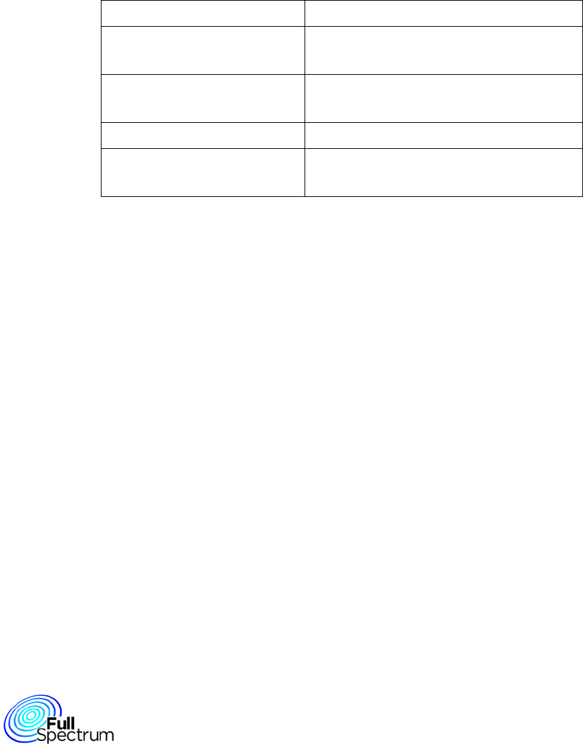
Enclosure Material Aluminum Alloy
Dimensions (W x D x H) 8.5” x 4.85” x 2.95”
(216mm x 123mm x 75mm)
Operating Temperature -40° F to 158° F
(-40° C to 70° C)
DC Input Power Range 24 to 68 VDC
Power Consumption No load : 13.1 watts @ 48 VDC
Peak load : 23.4 watts @ 48 VDC
Page 7 of 13 January 2017
2.2.2 Product Overview

Page 8 of 13 January 2017
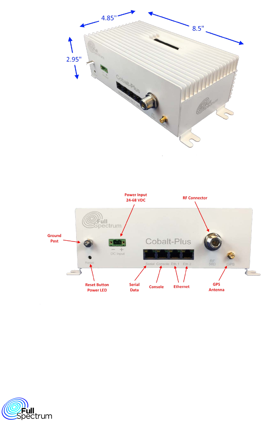
2.2.3 Connection Descriptions
Connector Application
GPS Antenna SMA female connector for optional GPS antenna.
RF Out 50Ω N-Type female connector for RF input from
antenna
DC Input DC power input 24-68 volts.
Warning: Ensure Correct Polarity
Ethernet 2 x RJ45 connector for Ethernet 10/100 Base-T
interface
Console (Serial) RJ45 8-pin connector wired using the Cisco
interface specification for console access
Serial Data RJ45 8-pin connector wired using the Cisco
interface specification for serial data
Ground Post Connection to building ground
Page 9 of 13 January 2017
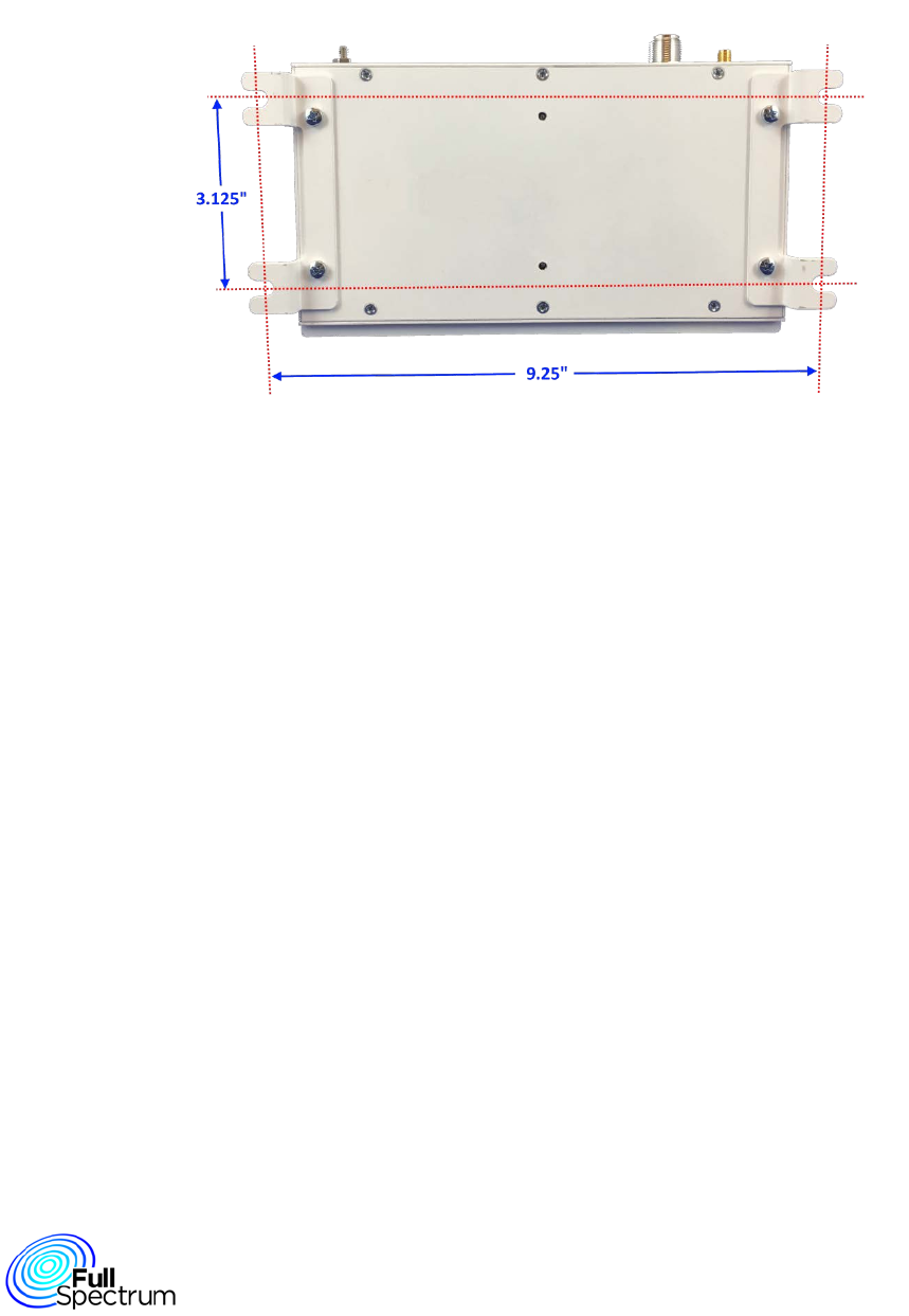
2.2.4 Mounting Guidelines
• A mounting bracket is provided for attaching the Cobalt-Plus enclosure to a vertical flat surface.
Page 10 of 13 January 2017
3 Operation and Configuration CLI Instructions
CLI show command
show ms bsid
it should display the mac address of the BS. cross checked with HW addr in BS.
show ms version
it should display the mac and phy load currently used.
HW version, mac FW and phy FW version given in the msconfig
should be displayed.
phy and mac load is fine. Others needs clarification
show ms ipconfig
ip configurations set in the msconfig should be displayed
irrespective of STATIC_IP_CONFIG enabled or disabled in the
config file.
cross checked with config file
show ms sysconfig
it should display all the configurations in the ms config file exept for
ip config.
cross checked with config file
show ms radioconfig
it should display radio configurations set in the ms config file. cross checked with config file
show ms scanconfig
it should display scan configurations set in the ms config file.
cross checked with config file and changes are reflected
upon soft reboot.
show ms phyconfig
it should display phy configurations set in the ms config file. cross checked with config file
show ms state
it should display the current state of the MS. When NE is happened
it should display as MS_OPERATIONAL.
When BS is switched off it shows DCD_UCD acquired
MS_OPERATION and DCD_UCD acquired state is
verified.
show ms capabilities
it should display all the basic capabilities supported by the MS.
show ms con statistics
upon giving this command consecutively the number of sdus in
and out should keep increasing when the NE is successful
show ms dcd
it should display the dcd configurations set in the ucddcd config file
for BS EIRP, EIRxPirmax, TTG, RTG, BSID.
BSID needs to be clarified
show ms info
clarrified ms state, ms mac addr, ms ip addr, ms peer
addr others needs to be clarified.
show ms l1if statistics
it should display all the l1If statistics like number of DL Burst
received from l1if , UL burst sent to l1If.
show ms memory statistics
it should display maximum buffer available, used and freed and
also number of enqueued, dequeued, totally available and free
msgs in a msg queue.
show ms rf statistics
it should display rf antenna statistics.
show ms sdu pool statistics
it should display maximum sdu nodes available, used and freed
shwo ms sfinfo
it should display informations of each service flows like: phs rule
supporting a SF, cid of a SF
show ms statistics
it should display the number of sdus received, sent, dropped,
memory allocated, errors occured in the system.
show ms timer statistics
it should display the numbers of timers created, started, deleted,
expired.
show ms ucd
it should display ucd configurations :number of init ranging codes,
periodic ranging codes, BW ranging codes, HO ranging codes
from the UCDDCD config file.
cross checked with config file
show ms measurement report
it should display CINR, Rx Gain, RSSI, fec code used values.
show ms ulmap burst <count>
show ms ulmap error <count>
show ms ulmap rcvd <count>
show ms csm statistics
show ms timing
show ms transmitted packet
show ms trigger metrics
show ms tx power
it should display MS tx power to the serving BS
show ms sainfo
show ms dlmap error <count>
show ms dlmap rcvd <count>
show ms decoded burst <count>
show ms encoded burst <count>
show ms received packet <count>

Page 11 of 13 January 2017
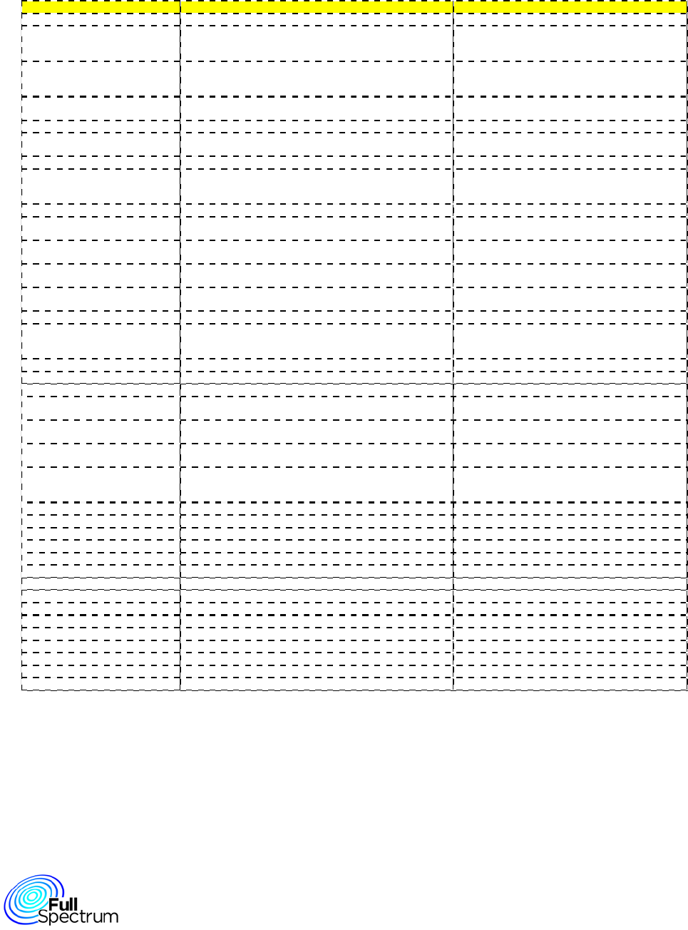
CLI Command
Description Parameter range How To Verify
config ms profile dl symbols <numOfSymbols> Used to configure dl symbols 19 to 169 show ms phyconfig & show ms sysconfig
config ms profile ul symbols <numOfSymbols> Used to configure ul symbols 19 to 169 show ms phyconfig & show ms sysconfig
config ms profile frame duration code
Used to configure frame duration by setting a value
which corresponds to certain frame duration
7 (fixed value) show ms phyconfig & show ms sysconfig
config ms profile channel bw <kHz> Used to set channnel bandwidth 500 to 1000 show ms phyconfig & show ms sysconfig
config ms profile dl zone Used to set number of DL zones 1show ms phyconfig & show ms sysconfig
config ms radio antenna <num> Used to configure number of radio antenna used 1 to 3 show ms phyconfig & show ms sysconfig
config ms radio agc enable Used to set automatic gain control 1show ms radioconfig & show ms sysconfig
config ms radio agc disable Used to reset automatic gain control 0show ms radioconfig & show ms sysconfig
config ms radio rxgain <gainIndB> Used to set receiver gain level 0-78 show ms radioconfig & show ms sysconfig
config ms radio txpcmode open
Used to set transmission power control to open loop
mode
4show ms measurement report
config ms radio txpcmode closed
Used to set transmission power control to closed
mode
1show ms measurement report
config ms radio txpcmode fixed
Used to set transmission power control to disabled
mode
0show ms measurement report
config ms radio maxtxpower <pwrIndB> Used to set maximum transmission power level ‐45 to 43 db show ms radioconfig & show ms sysconfig
config ms radio mintxpower <pwrIndB> Used to set minimum transmission power level ‐45 to 43 db show ms radioconfig & show ms sysconfig
config ms radio filterfile <filename> Used to set filter characteristics show ms sysconfig
config ms radio samplingclock
Used to set samplingClock; if ChannelBW=500 &
samplingClock=0,then samplingClock=560; else if
ChannelBW=1000 & samplingClock=0, then
samplingClock=1120
0 or 1120 khz show ms radioconfig & show ms sysconfig
config ms scan numbands <numbands> Used to set the number of bands to be scanned 1 to 8 show ms scanconfig & show ms sysconfig
config ms scan band <bandno> bandid
<bandid>
Used to set the band number & corresponding band
ID to be scanned
BandNo:1-8;
BandId:0-7
show ms scanconfig & show ms sysconfig
config ms scan band <bandno> bandrowstatus
<0/1>
Used to set the band number & corresponding band
status to be scanned
BandNo:1-8:
Bandrowstatus:0/1
show ms scanconfig & show ms sysconfig
config ms scan band <bandno> frequency
<freqinkHz>
Used to set the band number & corresponding
frequency to be scanned
BandNo:1-8;
Frequency:600000-
800000
show ms scanconfig & show ms sysconfig
config ms scan band <bandno> preamble
<preambleId>
Used to set the band number & corresponding
preamble to be scanned
BandNo:1-8;
Preamble:0-113
show ms scanconfig & show ms sysconfig
config ms scan band <bandno> sectorid
<sectorId
Used to set the band number & corresponding sector
ID to be scanned
BandNo:1-8;
SectorId:0-3
show ms scanconfig & show ms sysconfig
config ms scan band <bandno> cellid <cellId>
Used to set the band number & corresponding cell ID
to be scanned
BandNo:1-8; CellId:0-
31
show ms scanconfig & show ms sysconfig
config ms scan band <bandno> dlamcbm
<dlAmcBitmap>
Used to set the band number & corresponding DL
AMC Bitmap to be scanned
BandNo:1-8; DL
AMC Bitmap:0-63
show ms scanconfig & show ms sysconfig
config ms scan band <bandno> ulamcbm
<ulAmcBitmap>
Used to set the band number & corresponding UL
AMC Bitmap to be scanned
BandNo:1-8; UL
AMC Bitmap:0-63
show ms scanconfig & show ms sysconfig
config ms phy tx power max bpsk <db>
Used to set max transmission power for BPSK
modulation scheme
-39 to +43 show ms phyconfig & show ms sysconfig
config ms phy tx power max qpsk <db>
Used to set max transmission power for QPSK
modulation scheme
-39 to +43 show ms phyconfig & show ms sysconfig
Config CLI command
Page 12 of 13 January 2017
CLI Command
Description Parameter range How To Verify
config ms phy tx power max 16qam <db>
Used to set max transmission power for 16QAM
modulation scheme
-39 to +43 show ms phyconfig & show ms sysconfig
config ms phy tx power max 64qam <db>
Used to set max transmission power for 64QAM
modulation scheme
-39 to +43 show ms phyconfig & show ms sysconfig
config ms phy fixed timing adjust Used to enable or disable fixed timing 0/1 show ms phyconfig & show ms sysconfig
config ms phy initial timing adjust
Used to set initial timing of the MS to the amount of
internal fixed delay
0 to 65535 show ms sysconfig
config ms phy gps enable <1/0> Used to enable or disable gps 0/1 show ms phyconfig & show ms sysconfig
config ms phy gps delay Used to set gps delay 0 to 1024 show ms phyconfig & show ms sysconfig
config ms mac max fec dl <fec>
Used to indicate the maximum DL modulation that
can be configured
0 to 6 where:
0->QPSK
Convolutional
Code1/2;
1->QPSK CC3/4;
2->QAM16 CC1/2;
3->QAM16 CC3/4;
4->QAM64 CC1/2;
(3 & 4 Same);
5->QAM64 CC2/3;
6->QAM64 CC3/4
show ms sysconfig
config ms mac max fec ul <fec>
Used to indicate the maximum UL modulation that
can be configured
0 to 6 (Same as
above)
show ms sysconfig
config ms mac arq enable <1/0> Used to enable or disable ARQ 0/1 show ms sysconfig
config ms mac auth type <noauth=0/rsa=1/eap-
ttls+chapv0=2/eap-ttls+mschapv2=3)>
Used to set authentication type 0 to 3 show ms sysconfig
config ms mac encryption enable <1/0> Used to enable or disable Encryption 0/1 show ms sysconfig
config ms system timers lost dlmap intvl <ms>
Used to set the timer with lost DL Map interval in ms.
Waits for such time before MS moves to next band.
200 to 655000 show ms sysconfig
config ms system timers lost ulmap intvl <ms>
Used to set the timer with lost UL Map interval in ms.
Waits for such time before MS moves to next band.
200 to 655000 show ms sysconfig
config ms system timers dcd timeout <ms> Used to set the timer with DCD timeout value 500 to 50000 show ms sysconfig
config ms system timers ucd timeout <ms> Used to set the timer with UCD timeout value 500 to 50000 show ms sysconfig
config ms system timers broadcast ranging
timeout
Used to set T2 timeout 30 to 6000 show ms sysconfig
config ms system timers t3 timeout <ms> Used to set T3 RNG-RSP timeout 30 to 200 show ms sysconfig
config ms system timers periodic ranging timer
<s>
Used to set T4 Periodic ranging timer 500 to 60000 show ms sysconfig
config ms system timers t6 timeout Used to set T6 REG-RSP timeout 30 to 6000 show ms sysconfig
config ms system timers t7 timeout Used to set T7 DSX-RSP timeout 30 to 2000 show ms sysconfig
config ms system timers t8 timeout Used to set T8 DSX-ACK timeout 30 to 1000 show ms sysconfig
config ms system timers t10 timeout Used to set T10 DSX transaction timeout 30 to 6000 show ms sysconfig
config ms system timers t14 timeout Used to set T14 DSX RVD timeout 30 to 2000 show ms sysconfig
config ms system timers t18 timeout Used to set T18 SBC-RSP timeout 30 to 2000 show ms sysconfig
config ms system timers t42 timeout Used to set T42 MOB-HO-IND timeout 30 to 2000 show ms sysconfig
config ms system timers t43 timeout Used to set T43 MOB-SLP-RSP timeout 30 to 2000 show ms sysconfig
config ms system timers t44 timeout Used to set T44 MOB-SCN-RSP timeout 30 to 2000 show ms sysconfig
config ms system timers t45 timeout Used to set T45 DREG CMD Timeout 30 to 500 show ms sysconfig
config ms system timers traffic monitoring
timeout <s>
Used to set traffic monitoring timeout of the frames. If
Idle mode is enabled, MS triggers idle mode entry
after this amount of idle time.
30 to 3000000 show ms sysconfig
Config CLI command

Page 13 of 13 January 2017