Onkyo Ht S790 Users Manual S790_En
Onkyo-Ht-S7400-Owner-S-Manual onkyo-ht-s7400-owner-s-manual
HT-r540 ht-s790_manual_e
SKB-540 to the manual c3ab3fc3-d263-4c49-a1b0-e65d5594bd64
c3ab3fc3-d263-4c49-a.. c3ab3fc3-d263-4c49-a1b0-e65d5594bd64
2015-01-24
: Onkyo Onkyo-Ht-S790-Users-Manual-233284 onkyo-ht-s790-users-manual-233284 onkyo pdf
Open the PDF directly: View PDF ![]() .
.
Page Count: 80
- Instruction Manual
- Important Safety Instructions
- Precautions
- Speaker Precautions
- Enjoying Home Theater
- Package Contents
- Features
- Contents
- Getting to Know the AV Receiver
- Remote Controller
- Speakers
- Connecting Your Speakers
- Connecting Antennas
- Connecting Your Components
- About AV Connections
- Connecting Audio and Video Signals to the AV Receiver
- Which Connections Should I Use?
- Connecting a TV or Projector
- Connecting a DVD player
- Connecting a VCR or DVD Recorder for Playback
- Connecting a VCR or DVD Recorder for Recording
- Connecting a Camcorder, Games Console, or Other Device
- Connecting a Satellite, Cable, Set-top box, or Other Video Source
- Connecting a CD Player or Turntable
- Connecting an HDD-compatible Component
- Connecting a Cassette, CDR, MiniDisc, or DAT Recorder
- Connecting the Power Cord of Another Component
- Connecting Onkyo Components
- Connecting the Power Cord
- Turning On the AV Receiver
- First Time Setup
- Playing Your AV Components
- Listening to the Radio
- Common Functions
- Using the Listening Modes
- Advanced Setup
- Recording
- Controlling Other Components
- Troubleshooting
- Specifications
- Remote Control Codes

E
n
7.1ch Home Theater System
HT-S790
AV Receiver (HT-R540)
Front Speakers (SKF-540F)
Center Speaker (SKC-540C)
Surround Speakers (SKM-540S)
Surround Back Speakers (SKB-540)
Powered Subwoofer (SKW-540)
Instruction Manual
Thank you for purchasing an Onkyo 7.1ch Home
Theater System. Please read this manual thoroughly
before making connections and plugging in the unit.
Following the instructions in this manual will enable
you to obtain optimum performance and listening
enjoyment from your new 7.1ch Home Theater Sys-
tem.
Please retain this manual for future reference.
Contents
Introduction ..................................... 2
Connection .................................... 19
Turning On & First Time Setup..... 34
Basic Operation
Playing your AV components....... 36
Listening to the Radio.................. 38
Enjoying the Listening Modes ..... 46
Advanced Operation ..................... 52
Troubleshooting ............................ 61
HT-S790_En.book Page 1 Friday, February 17, 2006 3:28 PM
2
Important Safety Instructions
1. Read these instructions.
2. Keep these instructions.
3. Heed all warnings.
4. Follow all instructions.
5. Do not use this apparatus near water.
6. Clean only with dry cloth.
7. Do not block any ventilation openings. Install in
accordance with the manufacturer’s instructions.
8. Do not install near any heat sources such as radia-
tors, heat registers, stoves, or other apparatus
(including amplifiers) that produce heat.
9. Do not defeat the safety purpose of the polarized or
grounding-type plug. A polarized plug has two
blades with one wider than the other. A grounding
type plug has two blades and a third grounding
prong. The wide blade or the third prong are pro-
vided for your safety. If the provided plug does not
fit into your outlet, consult an electrician for
replacement of the obsolete outlet.
10. Protect the power cord from being walked on or
pinched particularly at plugs, convenience recepta-
cles, and the point where they exit from the appara-
tus.
11. Only use attachments/accessories specified by the
manufacturer.
12.
Use only with the cart, stand,
tripod, bracket, or table spec-
ified by the manufacturer, or
sold with the apparatus.
When a cart is used, use cau-
tion when moving the cart/
apparatus combination to
avoid injury from tip-over.
13. Unplug this apparatus during lightning storms or
when unused for long periods of time.
14. Refer all servicing to qualified service personnel.
Servicing is required when the apparatus has been
damaged in any way, such as power-supply cord or
plug is damaged, liquid has been spilled or objects
have fallen into the apparatus, the apparatus has
been exposed to rain or moisture, does not operate
normally, or has been dropped.
15. Damage Requiring Service
Unplug the apparatus from the wall outlet and refer
servicing to qualified service personnel under the
following conditions:
A. When the power-supply cord or plug is damaged,
B. If liquid has been spilled, or objects have fallen
into the apparatus,
C. If the apparatus has been exposed to rain or
water,
D. If the apparatus does not operate normally by
following the operating instructions. Adjust only
those controls that are covered by the operating
instructions as an improper adjustment of other
controls may result in damage and will often
require extensive work by a qualified technician
to restore the apparatus to its normal operation,
E. If the apparatus has been dropped or damaged in
any way, and
F. When the apparatus exhibits a distinct change in
performance this indicates a need for service.
16. Object and Liquid Entry
Never push objects of any kind into the apparatus
through openings as they may touch dangerous volt-
age points or short-out parts that could result in a
fire or electric shock.
The apparatus shall not be exposed to dripping or
splashing and no objects filled with liquids, such as
vases shall be placed on the apparatus.
Don’t put candles or other burning objects on top of
this unit.
17. Batteries
Always consider the environmental issues and fol-
low local regulations when disposing of batteries.
18. If you install the apparatus in a built-in installation,
such as a bookcase or rack, ensure that there is ade-
quate ventilation.
Leave 20 cm (8") of free space at the top and sides
and 10 cm (4") at the rear. The rear edge of the shelf
or board above the apparatus shall be set 10 cm (4")
away from the rear panel or wall, creating a flue-like
gap for warm air to escape.
WARNING:
TO REDUCE THE RISK OF FIRE OR ELECTRIC
SHOCK, DO NOT EXPOSE THIS APPARATUS
TO RAIN OR MOISTURE.
CAUTION:
TO REDUCE THE RISK OF ELECTRIC SHOCK,
DO NOT REMOVE COVER (OR BACK). NO
USER-SERVICEABLE PARTS INSIDE. REFER
SERVICING TO QUALIFIED SERVICE
PERSONNEL.
The lightning flash with arrowhead symbol, within an
equilateral triangle, is intended to alert the user to the
presence of uninsulated “dangerous voltage” within
the product’s enclosure that may be of sufficient
magnitude to constitute a risk of electric shock to
persons.
The exclamation point within an equilateral triangle is
intended to alert the user to the presence of important
operating and maintenance (servicing) instructions in
the literature accompanying the appliance.
WARNING
RISK OF ELECTRIC SHOCK
DO NOT OPEN
RISQUE DE CHOC ELECTRIQUE
NE PAS
OUVRIR
AVIS
PORTABLE CART WARNING
S3125A
HT-S790_En.book Page 2 Friday, February 17, 2006 3:28 PM

3
Precautions
1. Recording Copyright
—Unless it’s for personal use
only, recording copyrighted material is illegal with-
out the permission of the copyright holder.
2. AC Fuse
—The AC fuse inside the unit is not user-
serviceable. If you cannot turn on the unit, contact
your Onkyo dealer.
3. Care
—Occasionally you should dust the unit all
over with a soft cloth. For stubborn stains, use a soft
cloth dampened with a weak solution of mild deter-
gent and water. Dry the unit immediately afterwards
with a clean cloth. Don’t use abrasive cloths, thin-
ners, alcohol, or other chemical solvents, because
they may damage the finish or remove the panel let-
tering.
4. Power
WARNING
BEFORE PLUGGING IN THE UNIT FOR THE
FIRST TIME, READ THE FOLLOWING SEC-
TION CAREFULLY.
AC outlet voltages vary from country to country.
Make sure that the voltage in your area meets the
voltage requirements printed on the unit’s rear panel
(e.g., AC 230–240 V, 50 Hz or AC 120 V, 60 Hz).
Pressing the [STANDBY/ON] button to select
Standby mode does not fully shutdown the unit. If
you do not intend to use the unit for an extended
period, remove the power cord from the AC outlet.
5. Never Touch this Unit with Wet Hands—
Never
handle this unit or its power cord while your hands
are wet or damp. If water or any other liquid gets
inside this unit, have it checked by your Onkyo
dealer.
6. Handling Notes
• If you need to transport this unit, use the original
packaging to pack it how it was when you origi-
nally bought it.
• Do not leave rubber or plastic items on this unit
for a long time, because they may leave marks on
the case.
• This unit’s top and rear panels may get warm
after prolonged use. This is normal.
• If you do not use this unit for a long time, it may
not work properly the next time you turn it on, so
be sure to use it occasionally.
For U.S. models
FCC Information for User
CAUTION:
The user changes or modifications not expressly
approved by the party responsible for compliance could
void the user’s authority to operate the equipment.
NOTE:
This equipment has been tested and found to comply
with the limits for a Class B digital device, pursuant to
Part 15 of the FCC Rules. These limits are designed to
provide reasonable protection against harmful interfer-
ence in a residential installation.
This equipment generates, uses and can radiate radio
frequency energy and, if not installed and used in accor-
dance with the instructions, may cause harmful interfer-
ence to radio communications. However, there is no
guarantee that interference will not occur in a particular
installation. If this equipment does cause harmful inter-
ference to radio or television reception, which can be
determined by turning the equipment off and on, the
user is encouraged to try to correct the interference by
one or more of the following measures:
• Reorient or relocate the receiving antenna.
• Increase the separation between the equipment and
receiver.
•Connect the equipment into an outlet on a circuit dif-
ferent from that to which the receiver is connected.
•Consult the dealer or an experienced radio/TV techni-
cian for help.
For Canadian Models
NOTE:
THIS CLASS B DIGITAL APPARATUS
COMPLIES WITH CANADIAN ICES-003.
For models having a power cord with a polarized plug:
CAUTION:
TO PREVENT ELECTRIC SHOCK,
MATCH WIDE BLADE OF PLUG TO WIDE SLOT,
FULLY INSERT.
Modèle pour les Canadien
REMARQUE:
CET APPAREIL NUMÉRIQUE DE
LA CLASSE B EST CONFORME À LA NORME
NMB-003 DU CANADA.
Sur les modèles dont la fiche est polarisée:
ATTENTION:
POUR ÉVITER LES CHOCS ÉLEC-
TRIQUES, INTRODUIRE LA LAME LA PLUS
LARGE DE LA FICHE DANS LA BORNE CORRE-
SPONDANTE DE LA PRISE ET POUSSER
JUSQU’AU FOND.
HT-S790_En.book Page 3 Friday, February 17, 2006 3:28 PM

4
Speaker Precautions
Placement
• The speaker cabinets are made out of wood and are
therefore sensitive to extreme temperatures and
humidity, do not put them in locations subject to direct
sunlight or in humid places, such as near an air condi-
tioner, humidifier, bathroom, or kitchen.
•Do not put water or other liquids close to the speakers.
If liquid is spilled over the speakers, the drive units
may be damaged.
•Speakers should only be placed on sturdy, flat surfaces
that are free from vibration. Putting them on uneven or
unstable surfaces, where they may fall and cause dam-
age, will affect the sound quality.
• Subwoofer is designed to be used in the upright verti-
cal position only. Do not use it in the horizontal or
tilted position.
•If the unit is used near a turntable, CD player or DVD
player, howling or slipping of sound may occur. To
prevent this, move the unit away from the turntable,
CD player or DVD player otherwise lower the unit’s
output level.
Using Close to a TV or Computer
TVs and computer monitors are magnetically sensitive
devices and as such are likely to suffer discoloration or
picture distortion when conventional speakers are placed
nearby. To prevent this, the SKF-540F and SKC-540C
feature internal magnetic shielding. In some situations,
however, discoloration may still be an issue, in which case
you should turn off your TV or monitor, wait 15 to 30
minutes, and then turn it back on again. This normally
activates the degaussing function, which neutralizes the
magnetic field, thereby removing any discoloration
effects. If discoloration problems persist, try moving the
speakers away from your TV or monitor. Note that discol-
oration can also be caused by a magnet or demagnetizing
tool that’s too close to your TV or monitor.
Input Signal Warning
The speakers can handle the specified input power when
used for normal music reproduction. If any of the follow-
ing signals are fed to them, even if the input power is
within the specified rating, excessive current may flow in
the speaker coils, causing burning or wire breakage:
1.
Interstation noise from an untuned FM radio.
2.
Sound from fast-forwarding a cassette tape.
3.
High-pitched sounds generated by an oscillator, elec-
tronic musical instrument, and so on.
4.
Amplifier oscillation.
5.
Special test tones from audio test CDs and so on.
6.
Thumps and clicks caused by connecting or discon-
necting audio cables (Always turn off your amplifier
before connecting or disconnecting cables.)
7.
Microphone feedback.
HT-S790_En.book Page 4 Friday, February 17, 2006 3:28 PM
5
Enjoying Home Theater
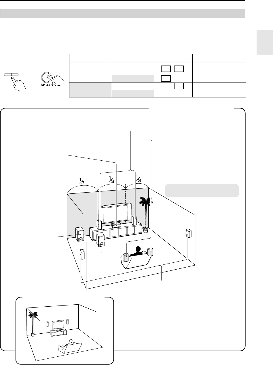
You can use two sets of speakers with the AV receiver:
speaker set A
and
speaker set B
.
Speaker set A
(included speakers) should be used in your main listening room for up to 7.1-channel playback.
*While speaker set B is on, speaker set A is reduced to 5.1-channel playback.
Speaker set B
(not included) can be used in another room and offers 2-channel stereo playback.
*Only analog input sources are output by speaker set B.
Speaker Sets A and B
Speaker set A Speaker set B Indicator Output
On On Set A: 5.1 channels
Set B: 2 channels
Off Set A: 7.1 channels
Off On Set B: 2 channels
Off No sound
AB
SPEAKERS
Remote
controller
AV receiver
or
A B
A
B
Surround back left and right
speakers (SKB-540)
These speakers further enhance the
realism of surround sound and
improve sound localization behind the
listener. Position them behind the lis-
tener about 2–3 feet (60–100 cm)
above ear level.
* While speaker set B is on, these
speakers output no sound.
Corner
1/3 wall
length
Speaker Set A: Main Room
Front left and right speakers (SKF-540F)
These output the overall sound. Their role in a home theater is to provide a solid anchor
for the sound image. They should be positioned facing the listener at about ear level,
and equally spaced from the TV. Angle them inward.
Center speaker (SKC-540C)
This speaker enhances the
front left and right speakers,
making sound movements
distinct and providing a full
sound image. For movies it’s
used mainly for dialog.
Position it close to your TV
facing forward at about ear
level, or at the same height as
the front left and right speak-
ers.
Surround left and right speakers (SKM-540S)
These speakers are used for precise sound posi-
tioning and to add realistic ambience. Position
them at the sides of the listener, or slightly behind,
about 2–3 feet (60–100 cm) above ear level. Ide-
ally they should be equally spaced from the lis-
tener.
Subwoofer (SKW-540)
The subwoofer handles the
bass sounds of the LFE (Low-
Frequency Effects) channel. In
general, a good bass sound
can be obtained by installing
the subwoofer in a front corner,
or at one-third the way along
the wall, as shown.
Speaker Set B: Sub Room
HT-S790_En.book Page 5 Friday, February 17, 2006 3:28 PM
6
Package Contents
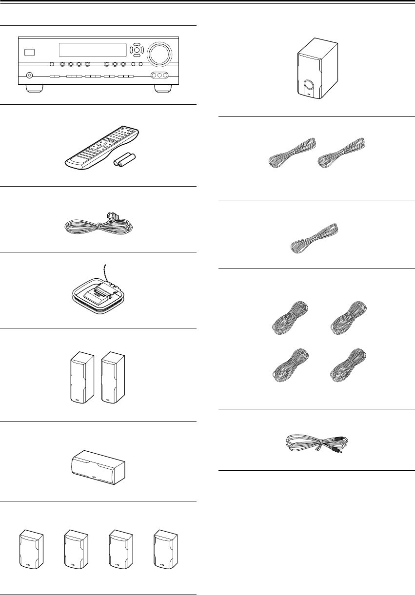
Make sure you have the following items:
* In catalogs and on packaging, the letter at the end of the
product name indicates the color. Specifications and oper-
ation are the same regardless of color.
AV receiver (HT-R540)
Remote controller & two batteries (AA/R6)
Indoor FM antenna
AM loop antenna
Front speakers (SKF-540F)
Center speaker (SKC-540C)
Surround and Surround back speakers
(SKM-540S/SKB-540)
Subwoofer (SKW-540)
Speaker cable for front speakers 15 ft. (4.5 m)
Speaker cable for center speaker 10 ft. (3 m)
Speaker cables for surround speakers 30 ft. (9 m)
RCA cable for subwoofer connection 10 ft. (3 m)
(Red) (White)
(Green)
(Blue) (Gray)
(Brown) (Tan)
HT-S790_En.book Page 6 Friday, February 17, 2006 3:28 PM

7
Features
Amplifier
• 7-channel amplifier
• 110 watts per channel rms into 8 ohms, 2 channels
driven at 1 kHz, less than 0.9% total harmonic distor-
tion (FTC rating)
• WRAT (Wide Range Amplifier Technology)
• Optimum Gain Volume Circuitry
• OR-EQ (OptiResponse Equalizer)
*1
function
Processing
• Dolby
*2
Digital EX and Dolby Pro Logic IIx
•DTS, DTS-ES Matrix/Discrete, DTS Neo:6, and DTS
96/24
*3
• Neural Surround
*4
(North American models only)
• CinemaFILTER function
• Linear PCM 192 kHz/24-bit D/A converters on all
channels
• Pure Audio listening mode (not North American
model)
•Powerful and highly accurate 32-bit DSP processing
Audio/Video
• Adjustable crossover (40, 50, 60, 80, 100, 120, 150,
200 Hz)
• HDTV-capable component video (3 inputs, 1 output)
•3 S-Video inputs, 2 outputs
•4 assignable digital inputs (3 optical, 1 coaxial)
• Subwoofer pre out
•Color-coded 7.1 multichannel input for use with Super
Audio CD and DVD-Audio
• A/B speaker drive
• Color-coded speaker terminal posts
Tuner
•XM
*5
Satellite Radio (North American models only)
*XM Passport System required; sold separately.
•40 AM/FM/XM presets
• AM/FM auto tuning
Remote Controller
• Preprogrammed for use with other AV components
Speaker
• Color-coded speaker terminals and speaker cables
• Subwoofer Auto standby function
• Magnetically shielded front and center speakers
• Floating tweeter on the front and center speakers
*1 OptiResponse, and OR-EQ are trademarks of Onkyo Cor-
poration.
*2
Manufactured under license from Dolby Laboratories.
“Dolby”, “Pro Logic” and the double-D symbol are regis-
tered trademarks of Dolby Laboratories.
*3
“DTS,” “DTS 96/24,” “DTS-ES,” and “Neo:6” are trade-
marks of Digital Theater Systems, Inc.
*4
Neural Surround name and related logos are trademarks
owned by Neural Audio Corporation.
*5
XM Ready
®
, XM Public Radio™ are trademarks of XM
Satellite Radio Inc. ©2005 XM Satellite Radio Inc. All
rights reserved. All other trademarks are the property of
their respective owners.
HT-S790_En.book Page 7 Friday, February 17, 2006 3:28 PM
8
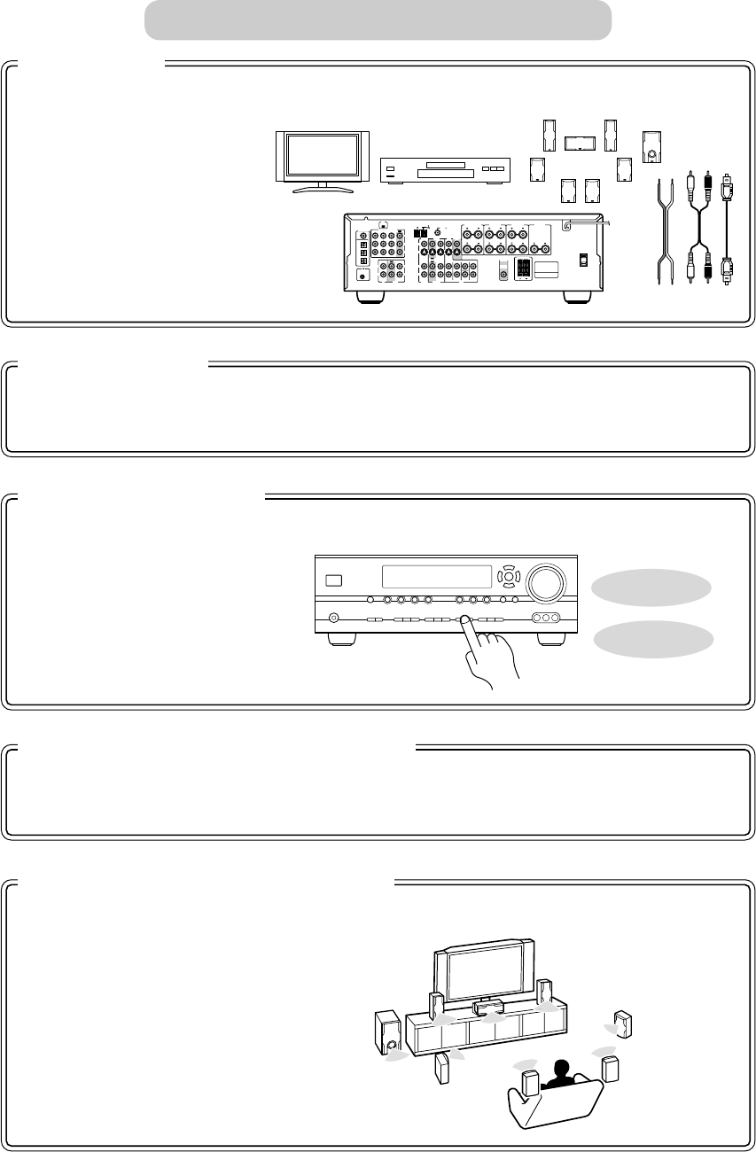
Connect the AV receiver to your AV system.
☞ page 19
COA
XIAL
REMOTE
CONTROL
OPTICAL
1
Y
PB
PR
2
3
DIGITAL IN
L
R
L
R
L
L
L
R
R
L
R
R
V
S
CD TAPE
XM ANTENNA
FM
AM 75
COMPONENT
VIDEO 2 IN
IN IN
OUT
OUT
IN IN
OUT
IN IN IN
OUT
VIDEO 1 IN DVD IN
VIDEO
VIDEO 2 VIDEO 1
VIDEO 2 VIDEO 1 DVD
DVD
MONITOR
OUT
SURROUND BACK
SPEAKERS
SURROUND
SPEAKERS
PRE OUT
SUB
WOOFER
SUB
WOOFER
FRONT
SURROUND
SURR BACK
CENTER
FRONT
SPEAKERS A
FRONT
SPEAKERS B
CENTER
SPEAKER
1. Hookup
With the hookup complete, you’re ready to switch on.
☞ page 34
2. Turning On
A few simple settings to get the very best from your system.
☞ page 35 Digital Input
Input Display
3. First Time Setup
Enjoying movies and music.
☞ page 36
4. Playing Your AV Components
Time to really enjoy your home theater system!
☞ page 46
5. Using the Listening Modes
Getting Started in Five Easy Steps
HT-S790_En.book Page 8 Friday, February 17, 2006 3:28 PM
9
Contents
Introduction
Important Safety Instructions ....................2
Precautions .................................................3
Speaker Precautions ..................................4
Enjoying Home Theater..............................5
Speaker Sets A and B ...................................5
Package Contents.......................................6
Features .......................................................7
Getting to Know the AV Receiver............10
Remote Controller.....................................13
Speakers ....................................................18
Connection
Connecting Your Speakers ......................19
Connecting Antennas...............................20
Connecting Your Components ................22
About AV Connections ................................22
Connecting Audio and Video Signals
to the AV Receiver ....................................23
Which Connections Should I Use?..............23
TV or Projector
..........................................24
DVD player
.................................................25
VCR or DVD Recorder for Playback ...........27
VCR or DVD Recorder for Recording..........28
Camcorder, Games Console,
or Other Device.........................................28
Satellite, Cable, Set-top box,
or Other Video Source ..............................29
CD Player or Turntable................................30
HDD-compatible Component ......................31
Cassette, CDR, MiniDisc,
or DAT Recorder.......................................32
Connecting the Power Cord of Another
Component ...............................................32
Connecting Onkyo Components
..........33
Connecting the Power Cord ........................33
Turning On & First Time Setup
Turning On the AV Receiver ....................34
First Time Setup........................................35
Assigning Digital Inputs to Input Sources....35
Changing the Input Display .........................35
Basic Operation
Playing Your AV Components ................ 36
Basic AV Receiver Operation ..................... 36
Using the Multichannel DVD Input.............. 37
Displaying Source Information.................... 37
Listening to the Radio.............................. 38
Listening to AM/FM stations ....................... 38
Presetting AM/FM Stations
and XM Channels..................................... 39
Listening to XM Satellite Radio
®
(North American Models Only) ................. 40
Common Functions.................................. 44
Setting the Display Brightness.................... 44
Adjusting the Bass and Treble.................... 44
Muting the AV Receiver .............................. 44
Using the OptiResponse Equalizer............. 44
Using the Sleep Timer ................................ 45
Using Headphones ..................................... 45
Adjusting Speaker Levels ........................... 45
Enjoying the Listening Modes
Using the Listening Modes...................... 46
Selecting Listening Modes.......................... 46
About the Listening Modes ......................... 48
Using the Late Night Function .................... 50
Using the CinemaFILTER........................... 50
Using the Audio Adjust Settings ................. 50
Advanced Operation
Advanced Setup ....................................... 52
Advanced Speaker Settings ....................... 52
Digital Input Signal Formats ....................... 56
Correcting Sound and Picture Sync ........... 56
Recording.................................................. 57
Controlling Other Components............... 58
Entering Remote Control Codes................. 58
Remote Control Codes for Onkyo
Components Connected via .............. 59
Resetting REMOTE MODE Buttons ........... 59
Resetting the Remote Controller ................ 59
Troubleshooting ....................................... 61
If you can’t resolve an issue, try resetting the AV
receiver by holding down the [VIDEO 1] button
and pressing the [STANDBY/ON] button.
Specifications ........................................... 65
HT-S790_En.book Page 9 Friday, February 17, 2006 3:28 PM
10
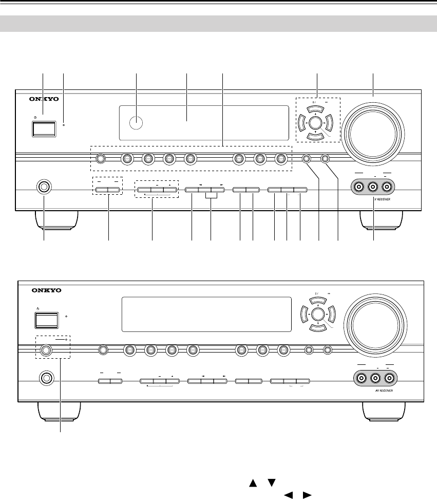
Getting to Know the AV Receiver
For detailed information, see the pages in parentheses.
A
STANDBY/ON button (34)
Sets the AV receiver to On or Standby.
B
STANDBY indicator (34)
Lights up when the AV receiver is on Standby and
flashes while a signal is being received from the
remote controller.
C
Remote-control sensor (13)
Receives control signals from the remote controller.
D
Display
See “Display” on page 11.
E
Input selector buttons (36)
Select the input sources.
The [MULTI CH] button selects the multichannel
DVD input.
F
Arrow/TUNING/PRESET and ENTER buttons
When AM, FM, or XM is selected, the TUNING
[] [ ] buttons are used for radio tuning, and the
PRESET [ ] [ ] buttons are used to select radio
presets (see page 39). With the setup menus, they
work as arrow buttons and are used to select and set
items. The ENTER button is also used with the
setup menus.
G
MASTER VOLUME control (36)
Sets the volume of the AV receiver to MIN, 1
through 79, or MAX.
H
PHONES jack (45)
This 1/4-inch phone jack is for connecting a stan-
dard pair of stereo headphones for private listening.
I
SPEAKERS A and B buttons (5, 36)
Turn speaker sets A and B on or off.
Front Panel
MASTER VOLUME
VIDEO
STANDBY
TONE DISPLAYSTEREO DIMMER MEMORY
DIGITAL
INPUT
TUNING
MODE
AB
SPEAKERS
TUNERTAPE
VIDEO 3VIDEO 2VIDEO 1
VCR
DVDMULTI CH C
DSETUPRETURN
CLEAR
LISTENING MODE
AUDIOLR
VIDEO 3 INPUT
STANDBY/ON
PHONES
TUNING PRESET
ENTER
1
TJKLMNOPQ89RS
23 5 6 74
MASTER VOLUME
VIDEO
STANDBY
TONE DISPLAYSTEREO DIMMER MEMORY
DIGITAL
INPUT
TUNING
MODE
AB
SPEAKERS
TUNERTAPE
VIDEO 3VIDEO 2VIDEO 1
VCR
DVDMULTI CH C
DSETUPRETURN
CLEAR
LISTENING MODE
AUDIOLR
VIDEO 3 INPUT
STANDBY/ON
PHONES
PURE AUDIO
TUNING PRESET
ENTER
U
North American Model
Other Models
HT-S790_En.book Page 10 Friday, February 17, 2006 3:28 PM
11
Getting to Know the AV Receiver
—Continued
J
TONE, [–], and [+] buttons (44)
Used to adjust the bass and treble.
K
STEREO button (46)
Selects the Stereo listening mode.
L
LISTENING MODE [ ]/[ ] buttons (46)
Select the listening modes.
M
DISPLAY button (37)
Displays various information about the currently
selected input source.
N
DIGITAL INPUT button (35, 56)
Used to assign the digital inputs and to specify the
format of digital input signals.
O
DIMMER button (44)
Adjusts the display brightness.
P
MEMORY button (39)
Used when storing or deleting radio presets.
Q
TUNING MODE button (38)
Selects the Auto or Manual tuning mode for AM
and FM radio.
R
RETURN button
Selects the previously displayed setup menu.
S
SETUP button
Used to access the setup menus.
T
VIDEO 3 INPUT (28, 57)
Used to connect a camcorder, games console, and so
on. There are jacks for composite video and analog
audio.
U
PURE AUDIO button and indicator (46)
The North American model doesn’t have this button
and indicator.
Selects the Pure Audio listening mode. The indica-
tor lights up when this mode is selected.
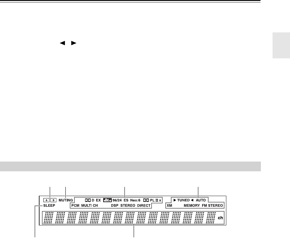
For detailed information, see the pages in parentheses.
1
A and B speaker indicators (5, 36)
Indicator A lights up when speaker set A is on. Indi-
cator B lights up when speaker set B is on.
2
MUTING indicator (44)
Flashes while the AV receiver is muted.
3
Listening mode and format indicators (48)
Show the selected listening mode and the format of
digital audio signals.
4
Radio indicators
TUNED (38):
Lights up when tuned to a radio sta-
tion.
AUTO (38):
For AM and FM radio, lights up when
Auto Tuning is selected, and disappears when Man-
ual Tuning mode is selected.
XM (North American models only) (40):
Lights up when XM radio is selected.
MEMORY (39):
Lights up when presetting radio
stations.
FM STEREO (38):
Lights up when tuned to a ste-
reo FM station.
5
SLEEP indicator (45)
Lights up when the Sleep function has been set.
6
Message area
Displays various information about the selected
input source.
Display
2134
56
HT-S790_En.book Page 11 Friday, February 17, 2006 3:28 PM
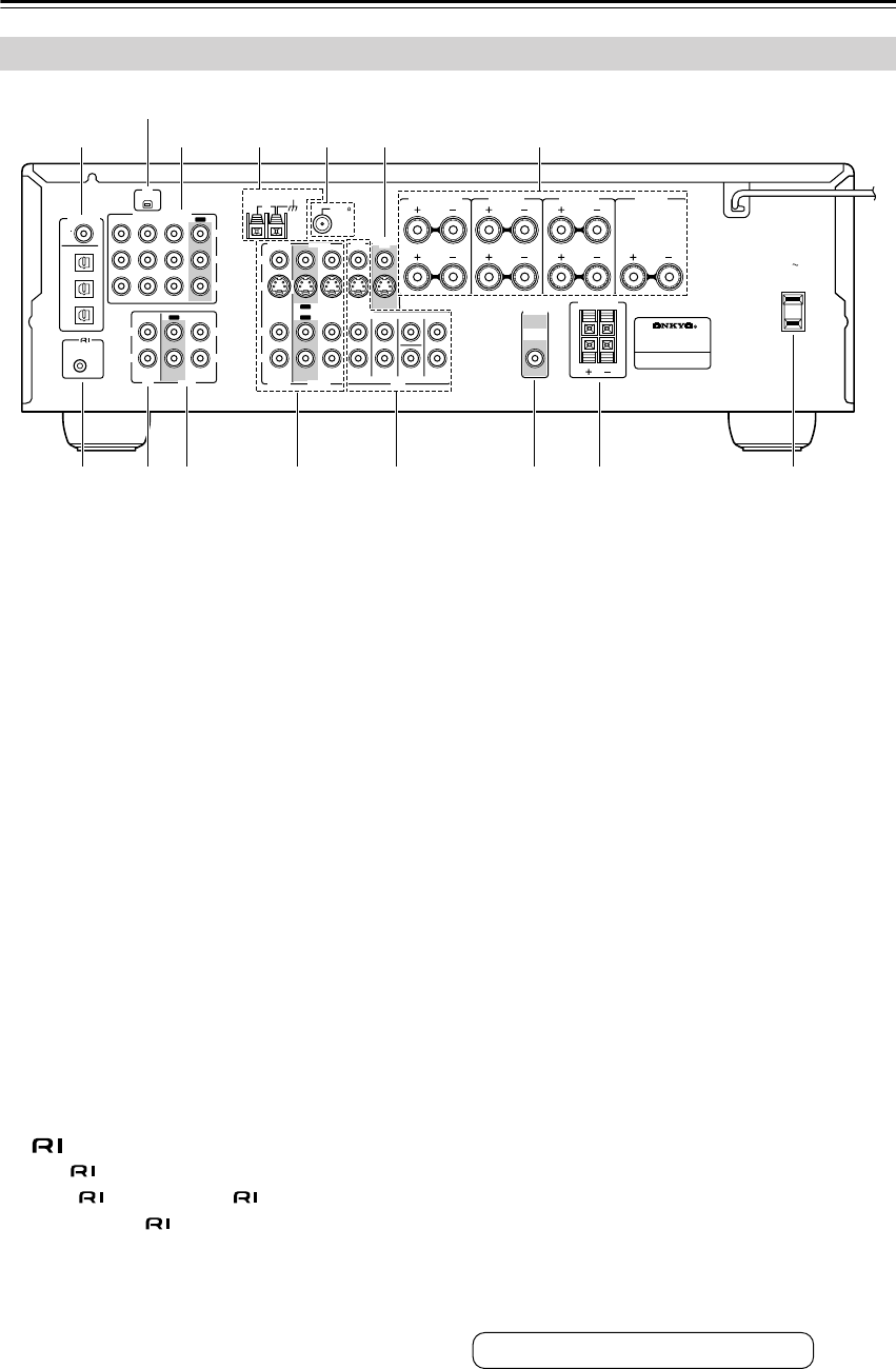
12
Getting to Know the AV Receiver
—Continued
A
DIGITAL IN OPTICAL 1, 2, 3, and COAXIAL
These optical and coaxial digital audio inputs are
for connecting components with optical or coaxial
digital audio outputs, such as CD and DVD players.
B
XM antenna (on North American models)
This jack is for connecting an XM Passport System,
sold separately (see page 40).
C
COMPONENT VIDEO
A DVD player, TV, or other component that sup-
ports component video can be connected here.
D
AM ANTENNA
These push terminals are for connecting an AM
antenna.
E
FM ANTENNA
This jack is for connecting an FM antenna.
F
MONITOR OUT
The S-Video or composite video output should be
connected to a video input on your TV or projector.
G
FRONT SPEAKERS A, SURROUND
SPEAKERS, CENTER SPEAKER, and
SURROUND BACK SPEAKERS
These terminal posts are for connecting speaker
set A.
H
REMOTE CONTROL
This Remote Interactive jack can be connected
to the jack on another -capable Onkyo com-
ponent. To use , you must make an analog audio
connection (RCA) between the AV receiver and the
other component, even if they are connected digi-
tally.
I
CD IN
This analog audio input is for connecting a CD
player’s analog audio output.
J
TAPE IN/OUT
This analog audio input and output are for connect-
ing a recorder with an analog audio input and out-
put, such as a cassette deck, MD recorder, etc.
K
VIDEO 1 IN/OUT and VIDEO 2 IN
The VIDEO 1 inputs and outputs can be used to
connect a VCR. The VIDEO 2 inputs can be used to
connect another video source (e.g., cable/satellite
receiver, set-top box, etc).
L
DVD IN
These jacks can be used to connect a DVD player
with an analog multichannel audio output for SACD
and DVD-Audio playback.
M
SUBWOOFER PRE OUT
A powered subwoofer can be connected here.
N
FRONT SPEAKERS B
These push terminals are for connecting speaker
set B.
O
AC OUTLET
This switched AC outlet can be used to supply
power to another AV component. The type of outlet
depends on the country in which you purchased
your AV receiver.
Rear Panel
COA
XIAL
REMOTE
CONTROL
OPTICAL
1
Y
PB
PR
2
3
DIGITAL IN
L
R
L
R
L
L
L
R
R
L
R
R
V
S
CD TAPE
XM ANTENNA
FM
AM 75
COMPONENT
VIDEO 2 IN
IN IN
OUT
OUT
IN IN
OUT
IN IN IN
OUT
VIDEO 1 IN DVD IN
VIDEO
VIDEO 2 VIDEO 1
VIDEO 2 VIDEO 1 DVD
DVD
MONITOR
OUT
SURROUND BACK
SPEAKERS
SURROUND
SPEAKERS
PRE OUT
SUB
WOOFER
SUB
WOOFER
FRONT
SURROUND
SURR BACK
CENTER
FRONT
SPEAKERS A
FRONT
SPEAKERS B
AV RECEIVER
AC OUTLET
AC 120V
SWITCHED
TOTAL 120W 1A MAX.
60Hz
CENTER
SPEAKER
8 9 J K L M O
1
B
4 53 6
N
7
(North American model only)
See pages 19–33 for hookup information.
HT-S790_En.book Page 12 Friday, February 17, 2006 3:28 PM
13
Remote Controller
Notes:
• If the remote controller doesn’t work reliably, try
replacing the batteries.
• Don’t mix new and old batteries or different types of
batteries.
•If you intend not to use the remote controller for a long
time, remove the batteries to prevent damage from
leakage or corrosion.
•Expired batteries should be removed as soon as possi-
ble to prevent damage from leakage or corrosion.
When using the remote controller, point it toward the AV
receiver’s remote control sensor, as shown below.
Notes:
•The remote controller may not work reliably if the AV
receiver is subjected to bright light, such as direct sun-
light or inverter-type fluorescent lights. Keep this in
mind when installing.
•If another remote controller of the same type is used in
the same room, or the AV receiver is installed close to
equipment that uses infrared rays, the remote control-
ler may not work reliably.
• Don’t put anything on top of the remote controller,
such as a book or magazine, because a button may be
pressed continuously, thereby draining the batteries.
•The remote controller may not work reliably if the AV
receiver is installed in a rack behind colored glass
doors. Keep this in mind when installing.
•The remote controller will not work if there’s an obsta-
cle between it and the AV receiver’s remote control
sensor.
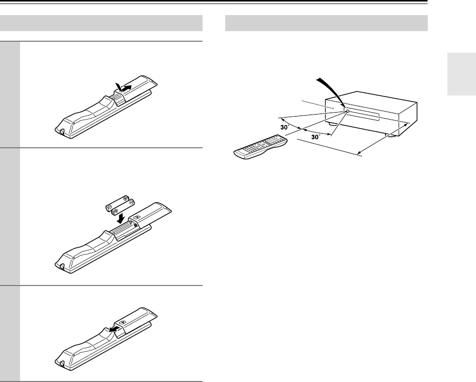
Installing the Batteries
1
To open the battery compartment, press
the small hollow and slide open the cover.
2
Insert the two supplied batteries (AA/R6)
in accordance with the polarity diagram
inside the battery compartment.
3
Slide the cover shut.
Aiming the Remote Controller
Approx. 16 ft.
(5 m)
Remote control sensor
STANDBY indicator
AV receiver
HT-S790_En.book Page 13 Friday, February 17, 2006 3:28 PM
14
Remote Controller
—Continued
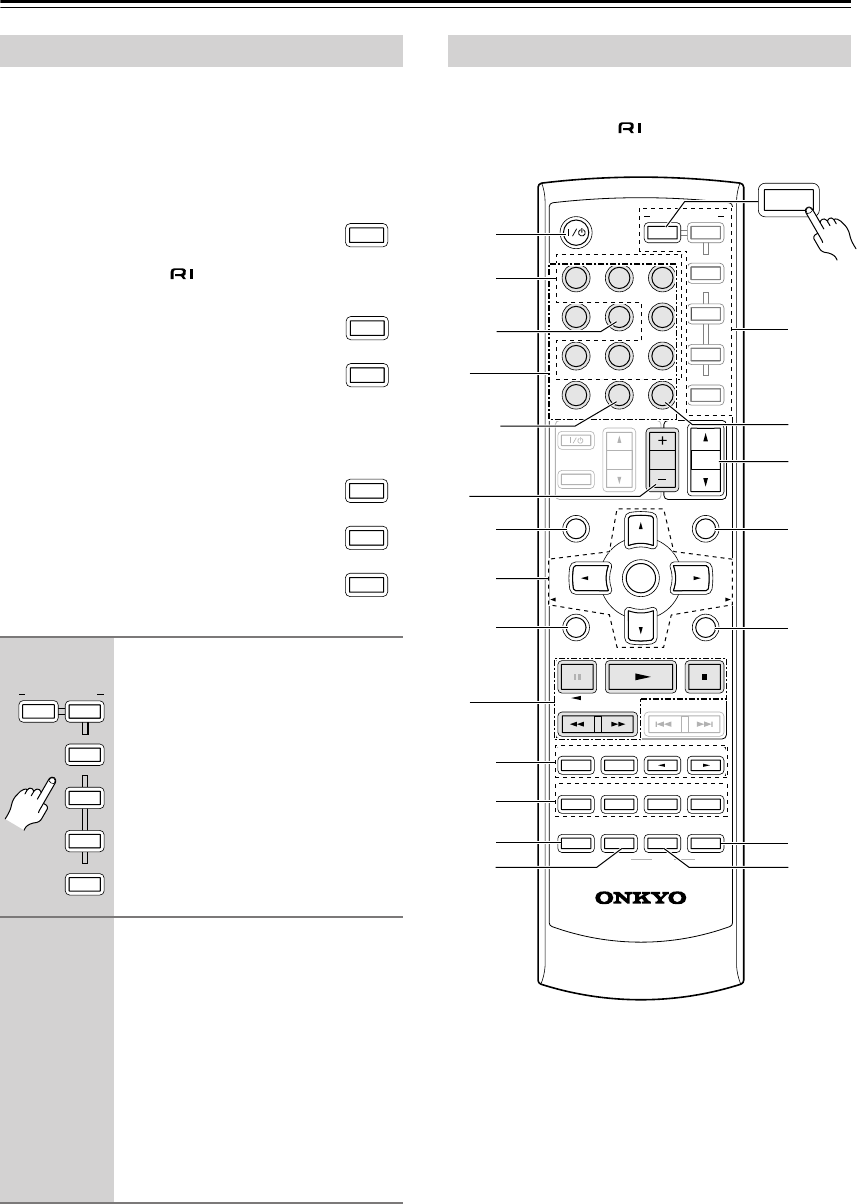
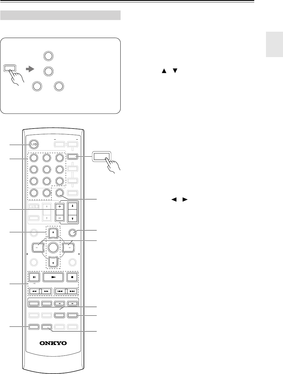
Including the AV receiver, the remote controller can be
used to control up to seven different components. The
remote controller has a specific operating mode for use
with each type of component. Modes are selected by
using the six REMOTE MODE buttons.
■
RECEIVER/TAPE Mode
In RECEIVER/TAPE mode, you can control
the AV receiver and an Onkyo cassette
recorder connected via .
■
DVD and CD/MD/CDR/HDD Modes
With these modes, you can control a DVD
player and CD, MD, CDR, or HDD player
or recorder. By entering the appropriate
remote control code, you can control Onkyo
components or components made by other
manufacturers (see page 58).
■
TV, VCR and SAT/CABLE Modes
With these modes, you can control a TV,
VCR, and satellite or cable receiver. You
must enter the appropriate remote control
code first (see page 58).
Note:
Some of the remote controller operations described in
this manual may not work as expected with other com-
ponents.
RECEIVER/TAPE mode is used to control the AV
receiver. It can also be used to control an Onkyo cassette
recorder connected via .
Buttons
1
,
2
,
3
, and
4
are used when the TUNER
or TAPE input is selected.
Using the Remote Controller
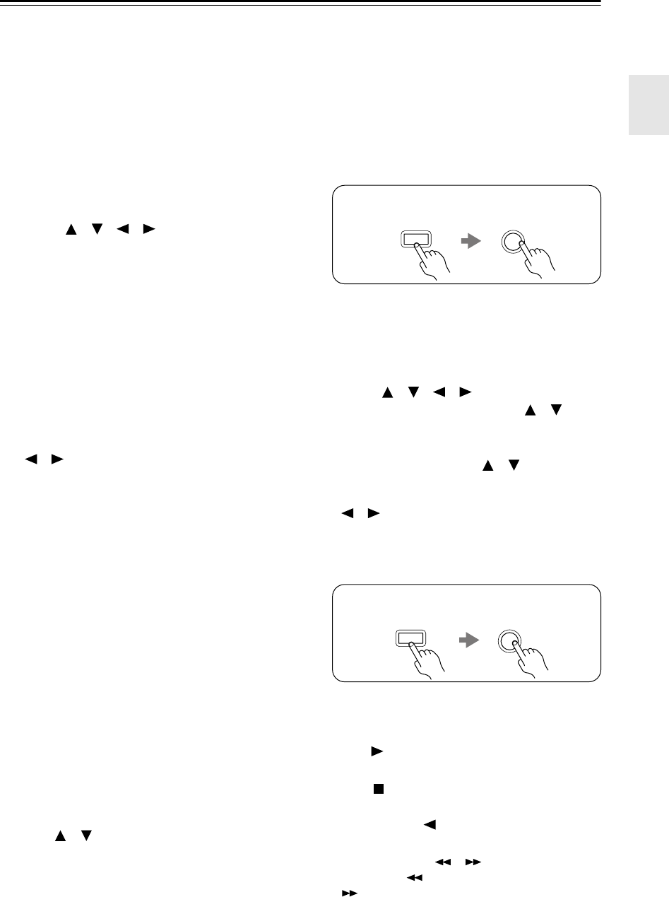
1
Press one of the REMOTE MODE
buttons to select a mode.
2
Use the buttons supported by
that mode to control the compo-
nent.
RECEIVER/TAPE mode:
see right column
DVD mode:
see page 16
CD/MD/CDR/HDD mode:
see page 17
TV, VCR, SAT/CABLE mode:
see page 60
TAPE
RECEIVER
M
D/CDR
HDD
DVD
C
D
CABLE
SAT
VCR
TV
TAPE
RECEIVER
M
D/CDR
HDD
CABLE
REMOTE MODE
SAT
VCR
TV
DVD
C
D
RECEIVER/TAPE Mode
MUTING
PREVIOUS
MENU
GUIDE
TOP MENU
SP A
/
B
SETUPRETURN
PLAYLIST/CAT PLAYLIST/CAT
RANDOM
SUBTITLE
PLAY MODE
AUDIO REPEAT
RC-649M
--
/
---
TAPE
M
D/CDR
HDD
CABLE
ON/STANDBY
DIMMER
ENT
D TUN
SLEEP
10 11 12
INPUT SELECTOR
HDDDVDVCR
REMOTE MODE
V
1
V
2
V
3
C
DTAPE TUNER
DVD
MULTI CH
LISTENING MODE
TV
DISPLAY
OR-EQ
TEST
TONE
CH SEL
SURROUND
STEREO
CINE FLTR
LEVEL
+
LEVEL
-
L NIGHT
VOL
VOL
SAT
VCR
TV
DVD
RECEIVER
C
D
INPUT
+10
0
CLR
123
456
789
ENTER
CH
DISC
ALBUM
TAPE
1
4
3
8
J
1
9
6
L
P
7
N
O
Q
R
5
RECEIVER
M
2
2
4
3
K
HT-S790_En.book Page 14 Friday, February 17, 2006 3:28 PM
15
Remote Controller
—Continued
For detailed information, see the pages in parentheses.
A
ON/STANDBY button (34)
Sets the AV receiver to On or Standby.
B
INPUT SELECTOR buttons (36)
Used to select the input sources.
C
MULTI CH button (37)
Selects the multichannel DVD input.
D
DIMMER button (44)
Adjusts the display brightness.
E
SP A/B button (5, 36)
Used to turn speaker sets A and B on or off.
F
Arrow [ ]/[ ]/[ ]/[ ] and ENTER buttons
Used to select and adjust settings.
G
RETURN button
Selects the previously displayed setup menu.
H
LISTENING MODE buttons (46)
Used to select the listening modes. These buttons
work in all remote controller modes.
STEREO button
Selects the Stereo listening mode.
SURROUND button
Selects the Dolby and DTS listening modes and the
Neural Surround listening mode (North American
model only).
[ ]/[ ] buttons
Used to select the available listening modes.
I
TEST TONE, CH SEL, LEVEL-, and LEVEL+
buttons (34, 45, 53)
Used to adjust the level of each speaker.
J
DISPLAY button (37)
Displays various information about the selected
input source.
K
OR-EQ button (44)
Turns on the OptiResponse Equalizer, which opti-
mizes performance when the HT-R540 is used with
the speakers included in this package. When the
OptiResponse Equalizer is on, you can enjoy a pow-
erful sound with movies or music even at low vol-
ume levels.
L
REMOTE MODE buttons (14)
Used to select the remote controller modes. When a
remote controller button is pressed, the REMOTE
MODE button for the currently selected mode lights
up.
M
SLEEP button (45)
Used with the Sleep function.
N
VOL [ ]/[ ] button (36)
Adjusts the volume of the AV receiver regardless of
the currently selected remote controller mode.
O
MUTING button (44)
Mutes or unmutes the AV receiver.
P
SETUP button
Used to access the setup menus.
Q
CINE FLTR button (50)
Used with the CinemaFILTER function.
R
L NIGHT button (50)
Used with the Late Night function.
■
Buttons used when the TUNER input is
selected
1
Number, D TUN, and ENT buttons (39, 41)
Used to select AM and FM radio stations and XM
radio channels directly.
2
CH +/– button (39)
Used to select radio presets.
3
Arrow [ ]/[ ]/[ ]/[ ] and ENTER buttons
For AM and FM, the Up and Down [ ]/[ ] but-
tons are used for tuning.
North American model only
For XM, the Up and Down [ ]/[ ] buttons are
used to select channels, and the [ENTER] button is
used to change the search mode. The Left and Right
[ ]/[ ] buttons are used to select categories.
■
Buttons used when the TAPE input is
selected
4
Playback buttons
On twin cassette decks, only deck B can be con-
trolled.
Play [ ] button
Starts playback.
Stop [ ] button
Stops playback.
Reverse Play [ ] button
Starts reverse playback.
Rewind and FF [ ]/[ ] buttons
The Rewind [ ] button starts rewind. The FF
[] button starts fast forward.
RECEIVER
TUNER
8
To select the Tuner (AM/FM/XM) as the
input source, press:
RECEIVER
TAPE
7
To select your Cassette deck as the input
source, press:
HT-S790_En.book Page 15 Friday, February 17, 2006 3:28 PM
16
Remote Controller
—Continued
By default, the remote controller is set to control an
Onkyo DVD player.
A
ON/STANDBY button
Sets the DVD player to On or Standby.
B
Number buttons
Used to enter title, chapter, and track numbers and
times for locating specific points.
C
DISC +/– button
Selects discs on a DVD changer.
D
TOP MENU button
Selects a DVD’s top menu.
E
Arrow [ ]/[ ]/[ ]/[ ] and ENTER buttons
Used to navigate DVD menus and the DVD player’s
onscreen setup menus.
F
RETURN button
Exits the DVD player’s onscreen setup menus.
G
Playback buttons
From left to right: Pause, Play, Stop, Fast Reverse,
Fast Forward, Previous, and Next.
H
SUBTITLE button
Selects subtitles.
I
AUDIO button
Selects foreign language soundtracks and audio for-
mats (e.g., Dolby Digital or DTS).
J
DISPLAY button
Displays information about the current disc, title,
chapter, or track, including elapsed time, remaining
time, total time, and so on.
K
CLR button
Cancels functions and clears entered numbers.
L
MENU button
Displays a DVD’s menu.
M
SETUP button
Used to access the DVD player’s onscreen setup
menus.
N
RANDOM button
Used with the random playback function.
O
REPEAT button
Used with the repeat playback functions.
P
VCR, DVD, and HDD buttons
Used to select VCR, HDD (hard disk drive), or
DVD playback on a VCR/DVD recorder with a
built-in hard disk drive.
Q
PLAY MODE button
Selects play modes on components with selectable
play modes.
DVD Mode
DVD
6
To select your DVD player as the input source, press:
RECEIVER
MULTI CH
5
or
MUTING
PREVIOUS
MENU
GUIDE
TOP MENU
SP A
/
B
SETUPRETURN
PLAYLIST/CAT PLAYLIST/CAT
RANDOM
SUBTITLE
PLAY MODE
AUDIO REPEAT
RC-649M
--
/
---
TAPE
M
D/CDR
HDD
CABLE
ON/STANDBY
DIMMER
ENT
D TUN
SLEEP
10 11 12
INPUT SELECTOR
HDDDVDVCR
REMOTE MODE
V
1
V
2
V
3
C
DTAPE TUNER
DVD
MULTI CH
LISTENING MODE
TV
DISPLAY
TEST
TONE
CH SEL
CH SEL
SURROUND
STEREO
CINE FLTR
LEVEL
+
LEVEL
-
L NIGHT
VOL
VOL
SAT
VCR
TV
DVD
RECEIVER
C
D
INPUT
+10
0
CLR
123
456
789
ENTER
CH
DISC
ALBUM
K
1
6
7
L
P
Q
5
4
8
2
3
N
M
O
9
J
DVD
HT-S790_En.book Page 16 Friday, February 17, 2006 3:28 PM
17
Remote Controller
—Continued
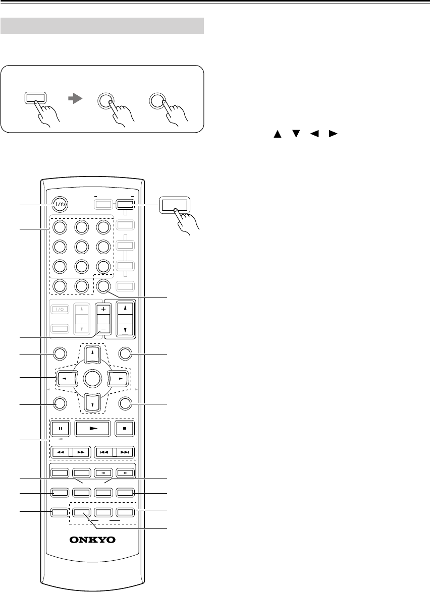
By default, the remote controller is set to control an
Onkyo CD player.
A
ON/STANDBY button
Sets the component to On or Standby.
B
Number buttons
Used to enter track numbers and times for locating
specific points on CD/MD players.
C
DISC/ALBUM +/– button
Selects discs on a CD changer, or the next or previ-
ous album on an HDD-compatible component.
D
Arrow [ ]/[ ] and ENTER buttons
Used to navigate menus on an HDD-compatible
component.
E
Playback buttons
From left to right: Pause, Play, Stop, Fast Reverse,
Fast Forward, Previous and Next.
F
DISPLAY button
Displays information about the current disc or track
on a CD player or MD/CD recorder, including
elapsed time, remaining time, total time, and so on.
On an HDD-compatible component, it turns on the
back light for 30 seconds.
G
CLR button
Cancels functions and clears entered numbers on a
CD player or MD/CD recorder.
H
MENU button
Used to navigate menus on an HDD-compatible
component.
I
PLAYLIST [ ]/[ ] buttons
Selects the previous or next playlist on an HDD-
compatible component.
J
RANDOM button
Used with the random/shuffle playback function.
K
REPEAT button
Used with the repeat playback functions.
L
PLAY MODE button
Used to select play modes on components with
selectable play modes.
CD/MD/CDR/HDD Mode
C
D
9
TAPE
7
V2
2
To select the input source, press:
CD player
MD or CD recorder
Next generation HDD-
compatible component
* If you’re using an MD, CDR, or HDD component, you
must change the Input Display (see page 35).
RECEIVER
TAPE
7or
MUTING
PREVIOUS
MENU
GUIDE
TOP MENU
SP A
/
B
SETUPRETURN
PLAYLIST/CAT PLAYLIST/CAT
RANDOM
SUBTITLE
PLAY MODE
AUDIO REPEAT
RC-649M
--
/
---
TAPE
M
D/CDR
HDD
CABLE
ON/STANDBY
DIMMER
ENT
D TUN
SLEEP
10 11 12
INPUT SELECTOR
HDDDVDVCR
REMOTE MODE
V
1
V
2
V
3
C
DTAPE TUNER
DVD
MULTI CH
LISTENING MODE
TV
DISPLAY
TEST
TONE
CH SEL
CH SEL
SURROUND
STEREO
CINE FLTR
LEVEL
+
LEVEL
-
L NIGHT
VOL
VOL
SAT
VCR
TV
DVD
RECEIVER
C
D
INPUT
+10
0
CLR
123
456
789
ENTER
CH
DISC
ALBUM
1
G
F
E
J
8
2
3
K
L
M
D/CDR
HDD
C
D
9
4
HT-S790_En.book Page 17 Friday, February 17, 2006 3:28 PM
18
Speakers
For detailed information, see the pages in parentheses.
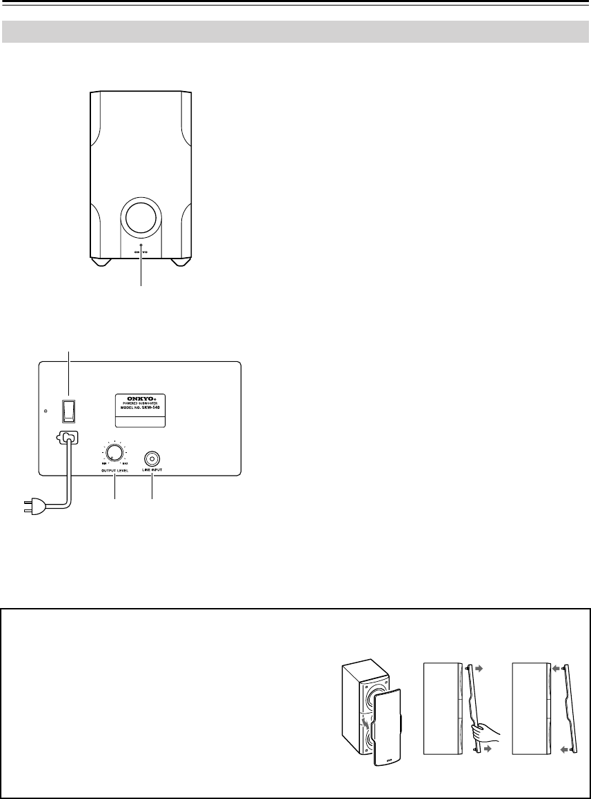
A
STANDBY/ON indicator
Red: Subwoofer in standby mode
Green: Subwoofer on
With the Auto Standby function, the SKW-540
automatically turns on when an input signal is
detected in Standby mode. When there’s no input
signal for a while, the SKW-540 automatically
enters Standby mode.
B
OUTPUT LEVEL control (36)
This control is used to adjust the volume of the sub-
woofer.
C
LINE INPUT (19)
This RCA input should be connected to the sub-
woofer pre out on the AV receiver with supplied
RCA cable.
D
POWER switch (Not North American model)
(34)
Press this switch to the ON position to turn on the
power. Press it to the OFF position to turn off the
power.
Note:
The Auto Standby function turns the subwoofer on when
the input signal exceeds a certain level. If the Auto
Standby function does not work reliably, try slightly
increasing or decreasing the subwoofer output level on
the AV receiver (page 53).
Subwoofer (SKW-540)
1
OFF
ON
POWER
2
4
3
■Rear
To AC outlet
■Front
(Not North American model)
■Attaching and detaching the speaker grilles
Front and Center speakers have detachable grilles. Use the
following method to attach or detach the grilles.
1. While holding the bottom edge of the speaker grille with
your both hands, pull it gently toward you to remove the
bottom of the grille.
2. In the same way, gently pull the upper edge of the
speaker grille toward you to remove it from the main
unit.
3. To replace the grill, push the projections at the corners
into the grille plug holes on the speaker cabinet.
ReplacementRemoval
HT-S790_En.book Page 18 Friday, February 17, 2006 3:28 PM
19
Connecting Your Speakers
Read the following before connecting your speakers:
•You can connect speakers with an impedance of
8 ohms or higher
. If you use speakers with a lower
impedance, and use the amplifier at high volume lev-
els for a long period of time, the built-in protection
circuit may be activated.
•Disconnect the power cord from the wall outlet before
making any connections.
•Pay close attention to speaker wiring polarity. In other
words, connect positive (+) terminals to only positive
(+) terminals, and negative (–) terminals to only nega-
tive (–) terminals. If you get them the wrong way
around, the sound will be out of phase and will sound
unnatural.
• Unnecessarily long, or very thin speaker cables may
affect the sound quality and should be avoided.
• Be careful not to short the
positive and negative wires.
Doing so may damage the AV
receiver.
• Don’t connect more than one
cable to each speaker termi-
nal. Doing so may damage the
AV receiver.
• Don’t connect one speaker to several terminals.
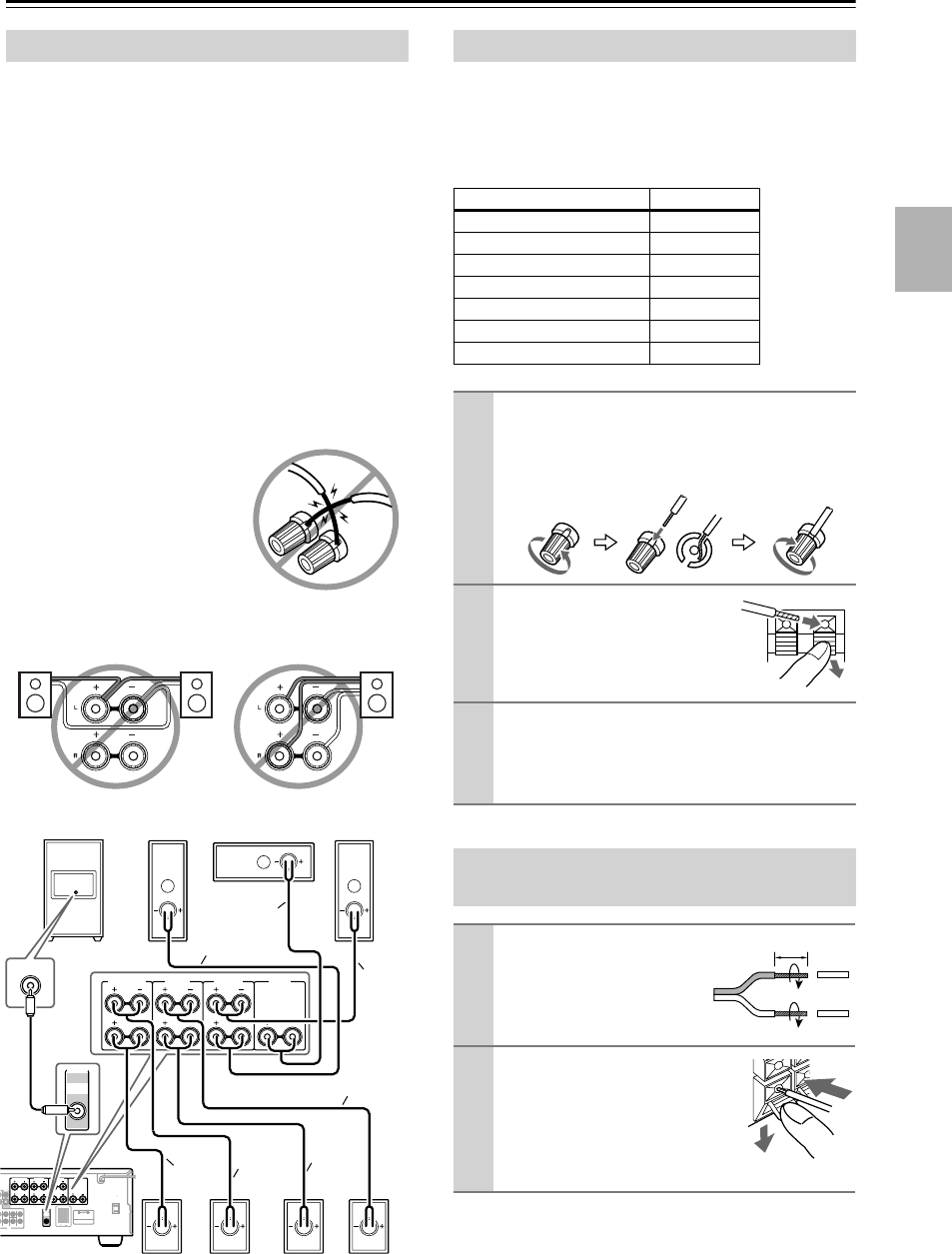
The AV receiver’s positive (+) speaker terminals and
speaker’s positive (+) terminals are color-coded for ease
of identification. (The negative (–) speaker terminals are
all black.) Match the color of each cable to the corre-
sponding speaker terminal.
Note:
When speaker set B is turned on, speaker set A is reduced
to 5.1-channel playback.
Speaker Connection Precautions
L
L
R
R
L
R
DVD
MONITOR
OUT
SURROUND BACK
SPEAKERS
SURROUND
SPEAKERS
PRE OUT
SUB
WOOFER
SUB
WOOFER
T
SURROUND
SURR BACK
CENTER
FRONT
SPEAKERS A
FRONT
SPEAKERS B
AV RECEIVER
AC OUTLET
AC 120V
SWITCHED
TOTAL120W 1A MAX.
60Hz
CENTER
SPEAKER
L
R
L
R
SURROUND BACK
SPEAKERS
SURROUND
SPEAKERS
FRONT
SPEAKERS A
CENTER
SPEAKER
PRE OUT
SUB
WOOFER
LINE INPUT
Red
Green
White
Blue
Gray
Brown
Ta n
Subwoofer Front Right Center Front Left
Surround
Back Right
Surround
Right
Surround
Back Left
Surround
Left
Connecting Speaker Set A
Speaker terminal Color
Front left White
Front right Red
Center Green
Surround left Blue
Surround right Gray
Surround back left Brown
Surround back right Tan
1
On the AV receiver, unscrew the terminal. Fully
insert the bare wires. Make sure that the bare wire
is touching the inside of the pole. Screw the termi-
nal tight.
2
On the speakers, while pressing
the terminal lever, insert the
wire into the hole, and then
release the lever.
3
Using the supplied RCA cable, connect the AV
receiver’s SUBWOOFER PRE OUT to LINE
INPUT on the subwoofer.
Make sure the cable is plugged all the way.
Connecting Speaker Set B (sold
separately)
1
Strip 3/8" (10 mm) of insu-
lation from the ends of the
speaker cables, and twist
the bare wires tightly, as
shown.
2
While pressing the lever, insert
the wire into the hole, and then
release the lever.
Make sure that the terminals are
gripping the bare wires, not the
insulation.
3/8" (10 mm)
HT-S790_En.book Page 19 Friday, February 17, 2006 3:28 PM
20
Connecting Antennas
This section explains how to connect the supplied indoor
FM antenna and AM loop antenna, and how to connect
commercially available outdoor FM and AM antennas.
The AV receiver won’t pick up any radio signals without
any antenna connected, so you must connect the antenna
to use the tuner.
The supplied indoor FM antenna is for indoor use only.
If you cannot achieve good reception with the supplied
indoor FM antenna, try a commercially available out-
door FM antenna instead (see page 21).
The supplied indoor AM loop antenna is for indoor use
only.
If you cannot achieve good reception with the supplied
indoor AM loop antenna, try using it with a commer-
cially available outdoor AM antenna (see page 21).
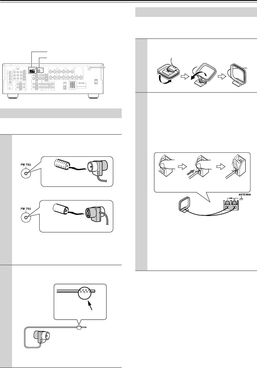
Connecting the Indoor FM Antenna
1
Attach the FM antenna, as shown.
■
American Model
■
Other Models
Once your AV receiver is ready for use, you’ll
need to tune into an FM radio station and adjust
the position of the FM antenna to achieve the best
possible reception.
2
Use thumbtacks or something similar to
fix the FM antenna into position.
Caution:
Be careful that you don’t injure yourself
when using thumbtacks.
COA
XIAL
REMOTE
CONTROL
OPTICAL
1
Y
PB
PR
2
3
DIGITAL IN
L
R
L
R
L
L
L
R
R
L
R
R
V
S
CD TAPE
XM ANTENNA
FM
AM 75
COMPONENT
VIDEO 2 IN
IN IN
OUT
OUT
IN IN
OUT
IN IN IN
OUT
VIDEO 1 IN DVD IN
VIDEO
VIDEO 2 VIDEO 1
VIDEO 2 VIDEO 1 DVD
DVD
MONITOR
OUT
SURROUND BACK
SPEAKERS
SURROUND
SPEAKERS
PRE OUT
SUB
WOOFER
SUB
WOOFER
FRONT
SURROUND
SURR BACK
CENTER
FRONT
SPEAKERS A
FRONT
SPEAKERS B
AV RECEIVER
AC OUTLET
AC 120V
SWITCHED
TOTAL120W 1A MAX.
60Hz
CENTER
SPEAKER
AM antenna push terminals
FM antenna jack
Insert the plug fully
into the jack.
Insert the plug fully
into the jack.
Thumbtacks, etc.
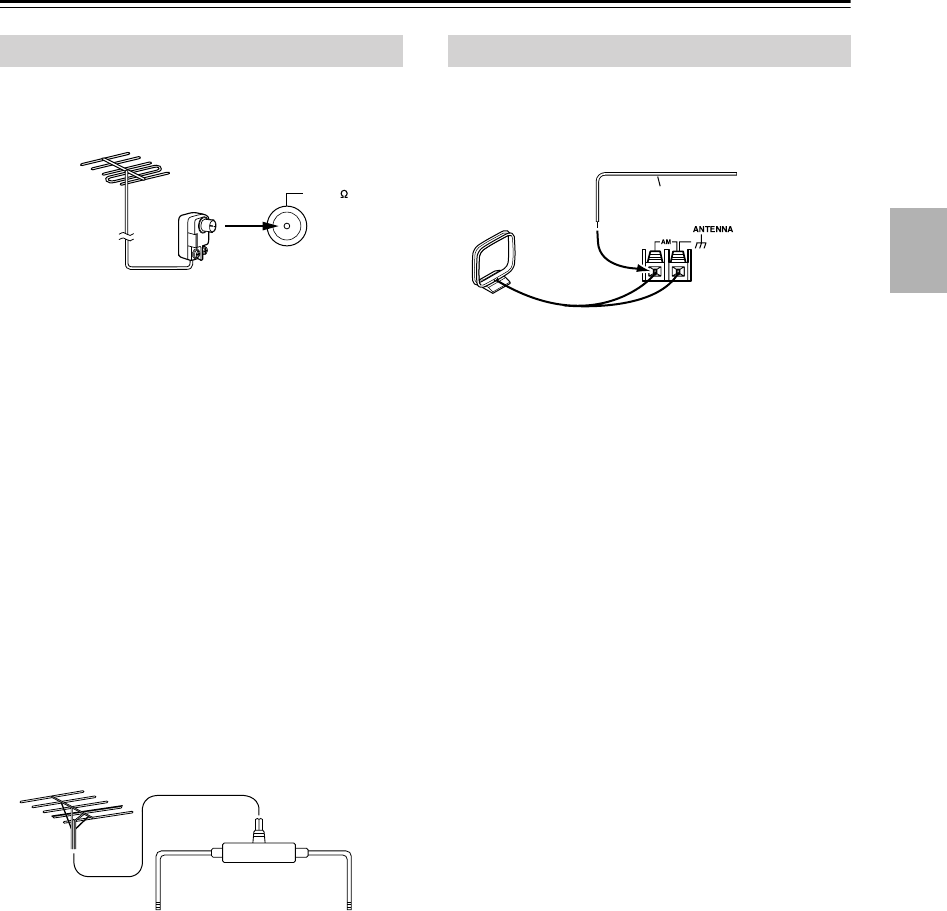
Connecting the AM Loop Antenna
1
Assemble the AM loop antenna, inserting
the tabs into the base, as shown.
2
Connect both wires of the AM loop
antenna to the AM push terminals, as
shown.
(The antenna’s wires are not polarity sensitive, so
they can be connected either way around).
Make sure that the wires are attached securely and
that the push terminals are gripping the bare
wires, not the insulation.
Once your AV receiver is ready for use, you’ll
need to tune into an AM radio station and adjust
the position of the AM antenna to achieve the best
possible reception.
Keep the antenna as far away as possible from
your AV receiver, TV, speaker cables, and power
cords.
Push Insert wire Release
HT-S790_En.book Page 20 Friday, February 17, 2006 3:28 PM
21
Connecting Antennas
—Continued
If you cannot achieve good reception with the supplied
indoor FM antenna, try a commercially available out-
door FM antenna instead.
Notes:
• Outdoor FM antennas work best outside, but usable
results can sometimes be obtained when installed in an
attic or loft.
•For best results, install the outdoor FM antenna well
away from tall buildings, preferably with a clear line
of sight to your local FM transmitter.
• Outdoor antenna should be located away from possi-
ble noise sources, such as neon signs, busy roads, etc.
•For safety reasons, outdoor antenna should be situated
well away from power lines and other high-voltage
equipment.
• Outdoor antenna must be grounded in accordance
with local regulations to prevent electrical shock haz-
ards.
■
Using a TV/FM Antenna Splitter
It’s best not to use the same antenna for both FM and TV
reception, as this can cause interference problems. If cir-
cumstances demand it, use a TV/FM antenna splitter, as
shown.
If good reception cannot be achieved using the supplied
AM loop antenna, an outdoor AM antenna can be used in
addition to the loop antenna, as shown.
Outdoor AM antennas work best when installed horizon-
tally outside, but good results can sometimes be obtained
indoors by mounting horizontally above a window. Note
that the AM loop antenna should be left connected.
Outdoor antenna must be grounded in accordance with
local regulations to prevent electrical shock hazards.
Connecting an Outdoor FM Antenna
FM 75
To AV receiver To TV (or VCR)
TV/FM antenna splitter
Connecting an Outdoor AM Antenna
Outdoor antenna
AM loop antenna
Insulated antenna cable
HT-S790_En.book Page 21 Friday, February 17, 2006 3:28 PM
22
Connecting Your Components
•Before making any AV connections, read the manuals
supplied with your other AV components.
•Don’t connect the power cord until you’ve completed
and double-checked all AV connections.
Optical Digital Jacks
The AV receiver’s optical digital jacks have shutter-type
covers that open when an optical plug is inserted and
close when it’s removed. Push plugs in all the way.
Caution:
To prevent shutter damage, hold the optical
plug straight when inserting and removing.
AV Connection Color Coding
RCA-type AV connections are usually color coded: red,
white, and yellow. Use red plugs to connect right-chan-
nel audio inputs and outputs (typically labeled “R”). Use
white plugs to connect left-channel audio inputs and out-
puts (typically labeled “L”). And use yellow plugs to
connect composite video inputs and outputs.
•Push plugs in all the way to make
good connections (loose connec-
tions can cause noise or malfunc-
tions).
•To prevent interference, keep
audio and video cables away from
power cords and speaker cables.
AV Cables and Jacks
About AV Connections
Left (white)
Right (red)
(Yellow)
Analog audio
Composite video
Left (white)
Right (red)
(Yellow)
Right!
Wrong!
Video
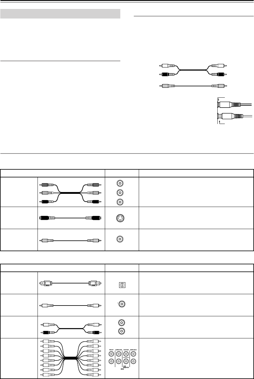
Cable Jack Description
Component
video cable
Component video separates the luminance (Y) and
color difference signals (P
R
, P
B
), providing the best
picture quality. (Some TV manufacturers label their
component video jacks slightly differently.)
S-Video cable
S-Video separates the luminance and color signals
and provides better picture quality than composite
video.
Composite
video cable
Composite video is commonly used on TVs, VCRs,
and other video equipment. Use only dedicated
composite video cables.
Audio
Cable Jack Description
Optical digital
audio cable
This offers the best sound quality and allows you to
enjoy Dolby Digital and DTS. The audio quality is
the same as for coaxial.
Coaxial digital
audio cable
This offers the best sound quality and allows you to
enjoy Dolby Digital and DTS. The audio quality is
the same as for optical.
Analog audio
cable (RCA)
This cable carries analog audio. It’s the most com-
mon connection format for analog audio and can be
found on virtually all AV components.
Multichannel
analog audio
cable (RCA)
This cable carries multichannel analog audio and is
typically used to connect DVD players with a 7.1-
channel analog audio output. Several standard ana-
log audio cables can be used instead of a multichan-
nel cable.
Y
P
R
P
B
P
R
P
B
Y
Y
PB
PR
S
V
OPTICAL
COA
XIAL
L
R
HT-S790_En.book Page 22 Friday, February 17, 2006 3:28 PM
23
Connecting Your Components
—Continued
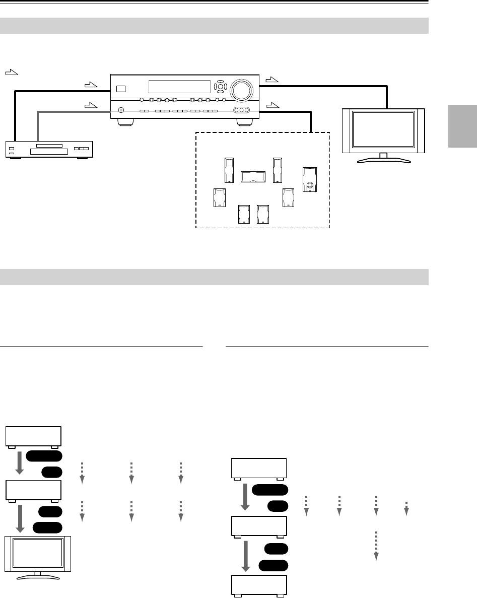
By connecting both the audio and video outputs of your DVD player and other AV components to the AV receiver, you
can switch the audio and video signals simultaneously simply by changing the input source on the AV receiver.
The AV receiver supports several connection formats for compatibility with a wide range of AV equipment. The format
you choose will depend on the formats supported by your other components. Use the following sections as a guide.
For video components, such as a DVD player, you must make an audio connection and a video connection.
Video Connection Formats
When choosing a connection format, bear in mind that
the AV receiver doesn’t convert between formats, so only
outputs of the same format as the input will output the
signal.
Video Signal Flow Chart
Audio Connection Formats
When choosing a connection format, bear in mind that
the AV receiver doesn’t convert between formats.
For example, audio signals connected to an OPTICAL or
COAXIAL digital input are not output by the analog
TAPE OUT, so if you want to record from, for example,
your CD player, in addition to connecting it to a digital
input, you must also connect it to the analog CD IN.
Audio Signal Flow Chart
Connecting Audio and Video Signals to the AV Receiver
Which Connections Should I Use?
: Signal Flow
Video Video
Audio
Speakers (see page 19 for hookup
details)
DVD player, etc.
TV, projector,
etc.
Audio
DVD player,
etc.
AV Receiver
TV,
projector,
etc.
Composite
IN
Input
Composite
Composite
S-Video
S-Video
S-Video
Component
Component
Component
OUT
Output
CD player,
etc.
AV Receiver
Cassette
recorder, etc.
Optical
Optical
Coaxial
Coaxial
Analog
Analog
Analog
Multi-
channel
Multi-
channel
IN
Input
OUT
Output
HT-S790_En.book Page 23 Friday, February 17, 2006 3:28 PM
24
Connecting Your Components
—Continued
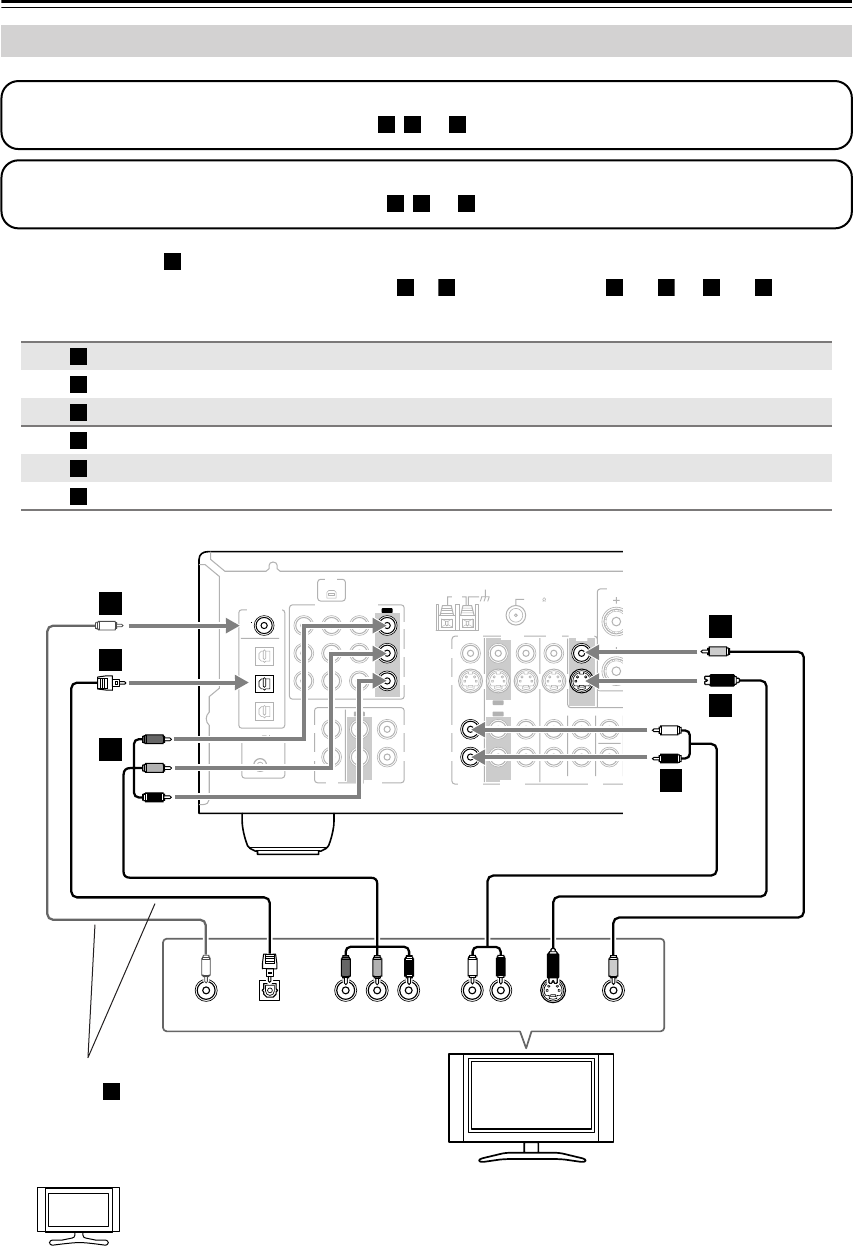
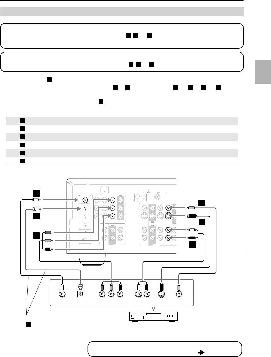
•With connection , you can listen to and record audio from your TV and listen via speaker set B.
•To enjoy Dolby Digital and DTS, use connection or . (For recording, use and , or and .)
If your TV has no audio outputs, connect an audio output from your VCR or cable or satellite
receiver to the AV receiver and use its tuner to listen to TV programs through the AV receiver (see
pages 27 and 29).
Connecting a TV or Projector
Connection AV receiver Signal flow TV Picture quality
COMPONENT VIDEO OUT
⇒
Component video input Best
MONITOR OUT S
⇒
S-Video input Better
MONITOR OUT V
⇒
Composite video input Standard
VIDEO 2 IN L/R
⇐
Analog audio L/R output
DIGITAL IN COAXIAL
⇐
Digital coaxial output
DIGITAL IN OPTICAL 2
⇐
Digital optical output
Step 1: Video Connection
Choose a video connection that matches your TV ( , , or ), and then make the connection.
A B
C
Step 2: Audio Connection
Choose an audio connection that matches your TV ( , , or ), and then make the connection.
a b c
a
b
c
a
b
a c
A
B
C
a
b
c
COA
XIAL
REMOTE
CONTROL
OPTICAL
1
Y
PB
PR
2
3
DIGITAL IN
L
R
L
R
L
L
L
R
R
L
R
R
V
S
CD TAPE
XM ANTENNA
FM
AM 75
COMPONENT
VIDEO 2 IN
IN IN
OUT
OUT
IN IN
OUT
IN IN IN
OUT
VIDEO 1 IN DVD IN
VIDEO
VIDEO 2 VIDEO 1
VIDEO 2 VIDEO 1 DVD
DVD
MONITOR
OUT
SURROUND BACK
SPEAKERS
SURROUND
SPEAKERS
PRE OUT
SUB
WOOFER
SUB
WOOFER
FRONT
SURROUND
SURR BACK
CENTER
FRONT
SPEAKERS A
FRONT
SPEAKERS B
C
S
YCOAXIAL
OUT
PB
COMPONENT VIDEO IN
PRS VIDEO
IN
AUDIO
OUT
VIDEO
IN
LR
OPTICAL
OUT
b
c
A
B
C
B
a
C
TV, projector,
etc.
Connect one or the other
Connection must be assigned (see page 35)
b
Hint!
HT-S790_En.book Page 24 Friday, February 17, 2006 3:28 PM
25
Connecting Your Components
—Continued
•With connection , you can listen to and record audio from a DVD and listen via speaker set B.
•To enjoy Dolby Digital and DTS, use connection or . (For recording, use and , or and .)
• If your DVD player has main left and right outputs and multichannel left and right outputs, be sure to use the
main left and right outputs for connection .
Connecting a DVD player
Connection AV receiver Signal flow DVD player Picture quality
COMPONENT VIDEO DVD IN
⇐
Component video output Best
DVD IN S
⇐
S-Video output Better
DVD IN V
⇐
Composite video output Standard
DVD IN FRONT
⇐
Analog audio L/R output
DIGITAL IN COAXIAL
⇐
Digital coaxial output
DIGITAL IN OPTICAL 1
⇐
Digital optical output
Step 1: Video Connection
Choose a video connection that matches your DVD player ( , , or ), and then make the connection.
You must connect the AV receiver to your TV via the same type of connection.
A B C
Step 2: Audio Connection
Choose an audio connection that matches your DVD player ( , , or ), and then make the connection.
a
b c
a
b c a b a c
a
A
B
C
a
b
c
COA
XIAL
REMOTE
CONTROL
OPTICAL
1
Y
PB
PR
2
3
DIGITAL IN
L
R
L
R
L
L
L
R
R
L
R
R
V
S
CD TAPE
XM ANTENNA
FM
AM 75
COMPONENT
VIDEO 2 IN
IN IN
OUT
OUT
IN IN
OUT
IN IN IN
OUT
VIDEO 1 IN DVD IN
VIDEO
VIDEO 2 VIDEO 1
VIDEO 2 VIDEO 1 DVD
DVD
MONITOR
OUT
SURROUND BACK
SPEAKERS
SURROUND
SPEAKERS
PRE OUT
SUB
WOOFER
SUB
WOOFER
FRONT
SURROUND
SURR BACK
CENTER
FRONT
SPEAKERS A
FRONT
SPEAKERS B
YCOAXIAL
OUT
PB
COMPONENT VIDEO OUT
PRS VIDEO
OUT
AUDIO
OUT
VIDEO
OUT
LR
OPTICAL
OUT
b
c
A
B
C
B
a
C
DVD player
To connect a DVD player or DVD-Audio/SACD-capable player with a
multichannel analog audio output, see page 26.
Connect one or the other
Connection must be assigned (see page 35)
c
HT-S790_En.book Page 25 Friday, February 17, 2006 3:28 PM
26
Connecting Your Components
—Continued
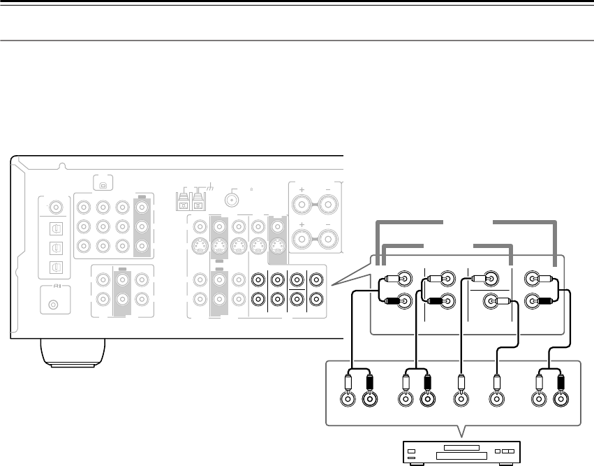
Hooking Up the Multichannel DVD Input
If your DVD player supports multichannel audio formats such as DVD-Audio or SACD, and it has a multichannel
analog audio output, you can connect it to the AV receiver’s multichannel DVD input.
Use a multichannel analog audio cable, or several normal audio cables, to connect the AV receiver’s DVD IN FRONT
L/R, CENTER, SURROUND L/R, SURR BACK L/R, and SUBWOOFER jacks to the 7.1-channel analog audio output
on your DVD player. If your DVD player has a 5.1-channel analog audio output, don’t connect anything to the AV
receiver’s SURR BACK L/R jacks.
COA
XIAL
REMOTE
CONTROL
OPTICAL
1
Y
PB
PR
2
3
DIGITAL IN
L
R
L
R
L
L
L
R
R
L
R
R
V
S
CD TAPE
XM ANTENNA
FM
AM 75
COMPONENT
VIDEO 2 IN
IN IN
OUT
OUT
IN IN
OUT
IN IN IN
OUT
VIDEO 1 IN DVD IN
VIDEO
VIDEO 2 VIDEO 1
VIDEO 2 VIDEO 1 DVD
DVD
MONITOR
OUT
SURROUND BACK
SPEAKERS
SURROUND
SPEAKERS
PRE OUT
SUB
WOOFER
SUB
WOOFER
FRONT
SURROUND
SURR BACK
CENTER
FRONT
SPEAKERS A
FRONT
SPEAKERS B
CENTER
SPEAKER
R
FRONT
LLR
SURROUND
CENTER SUB
WOOFER
FRONT
SURROUND
DVD
SUB
WOOFER
CENTER
R
L
R
L
LR
SURR
BACK
SURR BACK
5.1 ch
7.1 ch
DVD player
HT-S790_En.book Page 26 Friday, February 17, 2006 3:28 PM
27
Connecting Your Components
—Continued
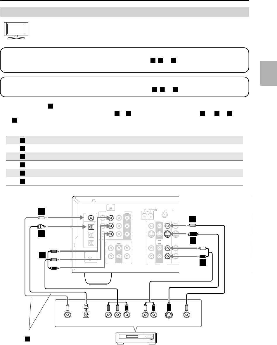
With this hookup, you can use your VCR’s tuner to listen to your favorite TV programs via the AV
receiver, useful if your TV has no audio outputs.
•With connection , you can listen to the VCR or DVD recorder even via speaker set B.
•To enjoy Dolby Digital and DTS, use connection or . (To listen via speaker set B, use and , or and
.)
Connecting a VCR or DVD Recorder for Playback
Connection AV receiver Signal flow VCR or DVD recorder Picture quality
COMPONENT VIDEO VIDEO 1 IN
⇐
Component video output Best
VIDEO 1 IN S
⇐
S-Video output Better
VIDEO 1 IN V
⇐
Composite video output Standard
VIDEO 1 IN L/R
⇐
Analog audio L/R output
DIGITAL IN COAXIAL
⇐
Digital coaxial output
DIGITAL IN OPTICAL 1
⇐
Digital optical output
Hint!
Step 1: Video Connection
Choose a video connection that matches your VCR or DVD recorder ( , , or ), and then make the connection.
You must connect the AV receiver to your TV via the same type of connection.
A
B
C
Step 2: Audio Connection
Choose an audio connection that matches your VCR or DVD recorder ( , , or ), and then make the connection.
a
b
c
a
b c a b a
c
A
B
C
a
b
c
COA
XIAL
REMOTE
CONTROL
OPTICAL
1
Y
PB
PR
2
3
DIGITAL IN
L
R
L
R
L
L
L
R
R
R
V
S
CD TAPE
XM ANTENNA
FM
AM 75
COMPONENT
VIDEO 2 IN
IN IN
OUT
OUT
IN IN
OUT
IN IN IN
OUT
VIDEO 1 IN DVD IN
VIDEO
VIDEO 2 VIDEO 1
VIDEO 2 VIDEO 1 DVD
DVD
MONITOR
OUT
SURROUND BACK
SPEAKERS
SURROUND
SPEAKERS
PRE OUT
SUB
WOOFER
SUB
WOOFER
FRONT
SURROUND
SURR BACK
CENTER
FRONT
SPEAKERS A
FRON
T
SPEAKE
R
YCOAXIAL
OUT
PB
COMPONENT VIDEO OUT
PRS VIDEO
OUT
AUDIO
OUT
VIDEO
OUT
LR
OPTICAL
OUT
b
c
A
B
C
B
a
C
VCR,
DVD recorder
Connect one or the other
Connection must be assigned (see page 35)
b
HT-S790_En.book Page 27 Friday, February 17, 2006 3:28 PM
28
Connecting Your Components
—Continued
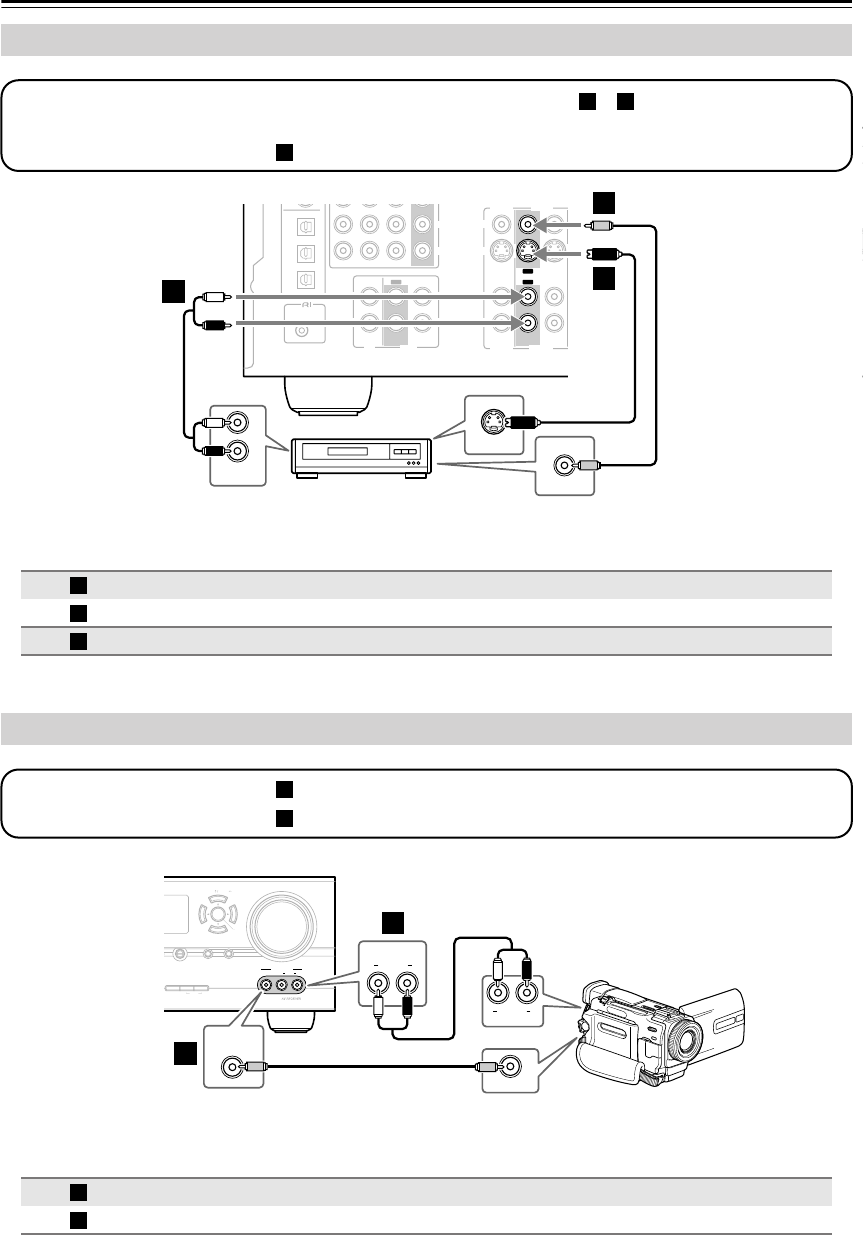
Connecting a VCR or DVD Recorder for Recording
Connection AV receiver Signal flow VCR or DVD recorder Picture quality
VIDEO 1 OUT S
⇒
S-Video input Better
VIDEO 1 OUT V
⇒
Composite video input Standard
VIDEO 1 OUT L/R
⇒
Analog audio L/R input —
Connecting a Camcorder, Games Console, or Other Device
Connection AV receiver Signal flow Camcorder or console
VIDEO 3 INPUT
⇐
Composite video output
VIDEO 3 INPUT L/R
⇐
Analog audio L/R output
COA
XIAL
REMOTE
CONTROL
OPTICAL
1
Y
PB
PR
2
3
DIGITAL IN
L
R
L
R
L
L
L
R
R
L
R
R
V
S
CD TAPE
XM ANTENNA
FM
AM 75
COMPONENT
VIDEO 2 IN
IN IN
OUT
OUT
IN IN
OUT
IN IN IN
OUT
VIDEO 1 IN DVD IN
VIDEO
VIDEO 2 VIDEO 1
VIDEO 2 VIDEO 1 DVD
DVD
MONITOR
OUT
SURROUND BACK
SPEAKERS
SURROUND
SPEAKERS
PRE OUT
SUB
WOOFER
SUB
WOOFER
FRONT
SURROUND
SURR BACK
CENTER
FRONT
SPEAKERS A
FRONT
SPEAKERS B
S
L
R
AUDIO
IN
S VIDEO IN
VIDEO IN
aA
B
B
Step 1: Choose a video connection that matches your VCR or DVD recorder ( or ), and then make the connec-
tion. The video source to be recorded must be connected to the AV receiver via the same type of connection.
Step 2: Make the audio connection .
A B
a
VCR,
DVD recorder
A
B
a
MASTER VOLUME
VIDEO
DIMMER MEMORY
DIGITAL
INPUT
TUNING
MODE
TUNER C
DSETUPRETURN
CLEAR
AUDIOLR
VIDEO 3 INPUT
TUNING PRESET
ENTER
VIDEO OUT
AUDIO
VIDEO 3 INPUT
LR
AUDIO
OUT
LR
VIDEO 3 INPUT
VIDEO
a
A
Step 1: Make the video connection .
Step 2: Make the audio connection .
A
a
Camcorder, games console, etc.
A
a
HT-S790_En.book Page 28 Friday, February 17, 2006 3:28 PM
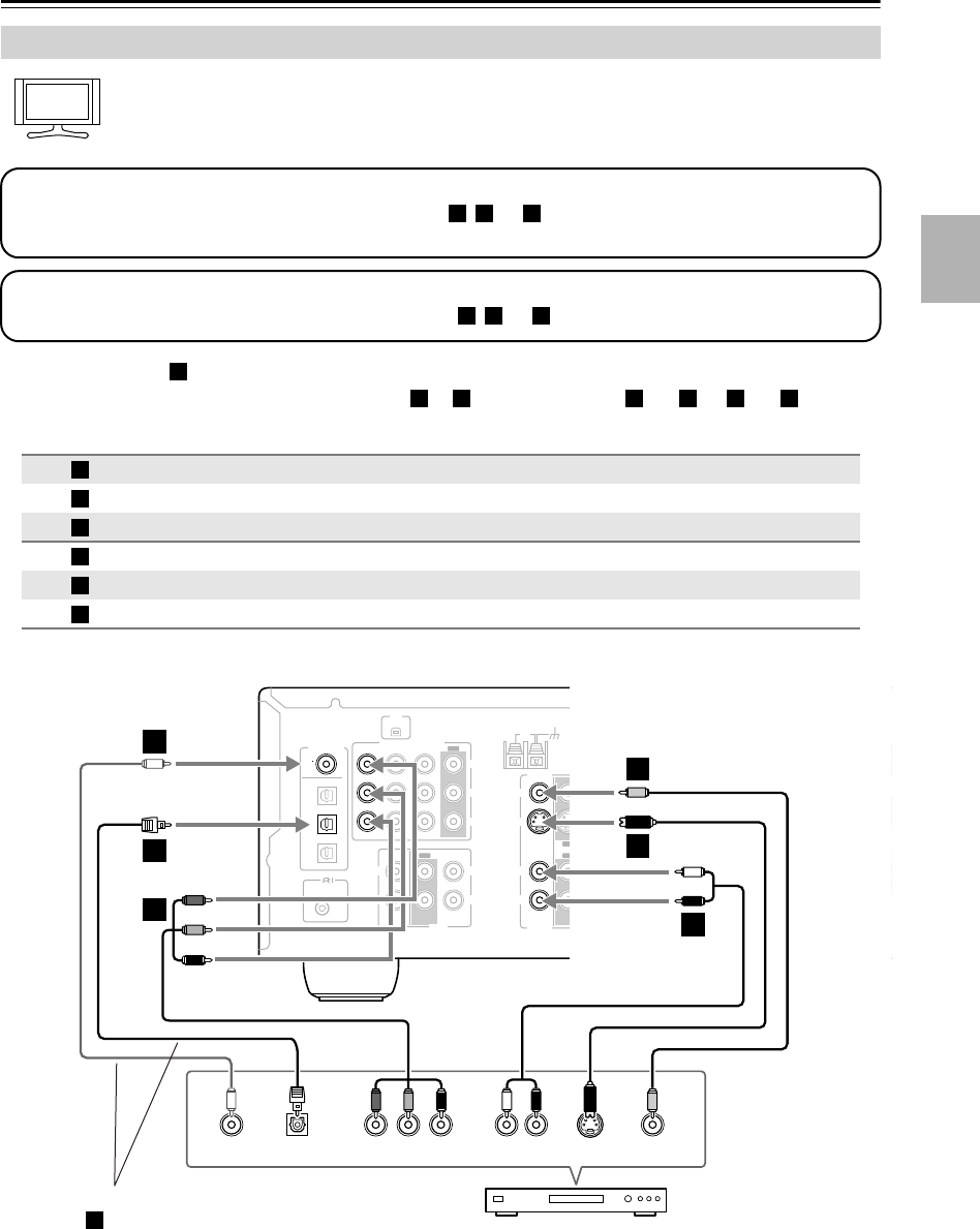
29
Connecting Your Components
—Continued
With this hookup, you can use your satellite or cable receiver to listen to your favorite TV programs
via the AV receiver, useful if your TV has no audio outputs.
•With connection , you can listen to and record audio from the video source and listen via speaker set B.
•To enjoy Dolby Digital and DTS, use connection or . (For recording, use and , or and .)
Connecting a Satellite, Cable, Set-top box, or Other Video Source
Connection AV receiver Signal flow Video source Picture quality
COMPONENT VIDEO VIDEO 2 IN
⇐
Component video output Best
VIDEO 2 IN S
⇐
S-Video output Better
VIDEO 2 IN V
⇐
Composite video output Standard
VIDEO 2 IN L/R
⇐
Analog audio L/R output
DIGITAL IN COAXIAL
⇐
Digital coaxial output
DIGITAL IN OPTICAL 2
⇐
Digital optical output
Hint!
Step 1: Video Connection
Choose a video connection that matches the video source ( , , or ), and then make the connection.
You must connect the AV receiver to your TV via the same type of connection.
A
B
C
Step 2: Audio Connection
Choose an audio connection that matches the video source ( , , or ), and then make the connection.
a b c
a
b c a b a c
A
B
C
a
b
c
COA
XIAL
REMOTE
CONTROL
OPTICAL
1
Y
PB
PR
2
3
DIGITAL IN
L
R
L
R
L
L
L
R
R
R
V
S
CD TAPE
XM ANTENNA
FM
AM 75
COMPONENT
VIDEO 2 IN
IN IN
OUT
OUT
IN IN
OUT
IN IN IN
OUT
VIDEO 1 IN DVD IN
VIDEO
VIDEO 2 VIDEO 1
VIDEO 2 VIDEO 1 DVD
DVD
MONITOR
OUT
SURROUND BACK
SPEAKERS
SURROUND
SPEAKERS
PRE OUT
SUB
WOOFER
SUB
WOOFER
FRONT
SURROUND
SURR BACK
CENTER
FRONT
SPEAKERS A
FRO
N
SPEAK
E
YCOAXIAL
OUT
PB
COMPONENT VIDEO OUT
PRS VIDEO
OUT
AUDIO
OUT
VIDEO
OUT
LR
OPTICAL
OUT
b
c
A
B
C
B
a
C
Satellite, cable, set-top box, etc.
Connect one or the other
Connection must be assigned (see page 35)
b
HT-S790_En.book Page 29 Friday, February 17, 2006 3:28 PM
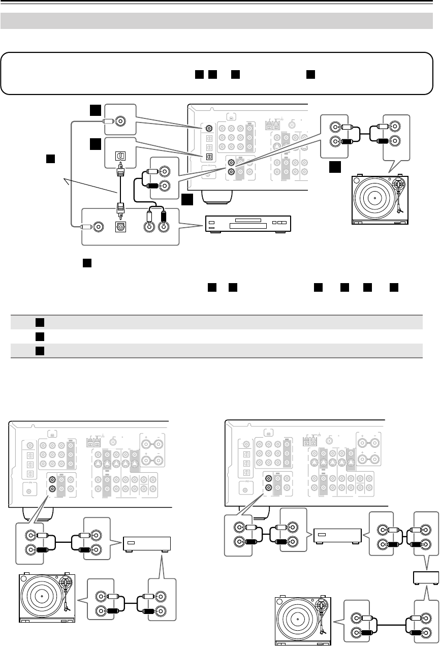
30
Connecting Your Components
—Continued
■
CD Player or Turntable (MM) with Built-in Phono Preamp
•With connection , you can listen to and record audio from your CD player or turntable and listen via speaker
set B.
•To connect the CD player digitally, use connection or . (For recording, use and , or and .)
■
Turntable (MM) with no Phono Preamp Built-in
A phono preamp is necessary to connect a turntable that
doesn’t have a phono preamp built-in.
■
Turntable with an MC (Moving Coil) Cartridge
An MC head amp and phono preamp are necessary to
connect a turntable with an MC (Moving Coil) cartridge.
Connecting a CD Player or Turntable
Connection AV receiver Signal flow CD or turntable
CD IN L/R
⇐
Analog audio L/R output
DIGITAL IN COAXIAL
⇐
Digital coaxial output
DIGITAL IN OPTICAL 3
⇐
Digital optical output
COA
XIAL
REMOTE
CONTROL
OPTICAL
1
Y
PB
PR
2
3
DIGITAL IN
L
R
L
R
L
L
R
R
V
S
CD TAPE
XM ANTENNA
FM
AM 75
COMPONENT
VIDEO 2 IN
IN IN
OUT
OUT
IN IN
OUT
IN IN IN
OUT
VIDEO 1 IN DVD IN
VIDEO
VIDEO 2 VIDEO 1
VIDEO 2 VIDEO 1 DVD
DVD
MONITOR
OUT
SURROUND BACK
SPEAKERS
SUB
WOOFER
FRONT
SURROUND
SURR BACK
CENTER
IN
L
R
L
R
CD AUDIO
OUTPUT
OPTICAL
3
OPTICAL
OUT
AUDIO
OUT
LR
DIGITAL IN
COAXIAL
COAXIAL
OUT
L
R
IN
CD
b
c
a
a
Step 1:
Choose a connection that matches your CD player ( , , or ). Use connection for a turntable with a built-in
phono preamp.
a b c a
Turntable (MM) with
built-in phono preamp
CD player
Connect one or
the other
Connection
must be
assigned (see
page 35)
b
a
b
c
a b a c
a
b
c
COA
XIAL
REMOTE
CONTROL
OPTICAL
1
Y
PB
PR
2
3
DIGITAL IN
L
R
L
R
L
L
R
R
V
S
CD TAPE
XM ANTENNA
FM
AM 75
COMPONENT
VIDEO 2 IN
IN IN
OUT
OUT
IN IN
OUT
IN IN IN
OUT
VIDEO 1 IN DVD IN
VIDEO
VIDEO 2 VIDEO 1
VIDEO 2 VIDEO 1 DVD
DVD
MONITOR
OUT
SURROUND BACK
SPEAKERS
SUB
WOOFER
FRONT
SURROUND
SURR BACK
CENTER
IN
L
R
CD
AUDIO
OUTPUT
AUDIO
OUTPUT
AUDIO
INPUT
L
R
L
R
L
R
Phono preamp L
R
L
R
L
R
L
R
COA
XIAL
REMOTE
CONTROL
OPTICAL
1
Y
PB
PR
2
3
DIGITAL IN
L
R
L
R
L
L
R
R
V
S
CD TAPE
XM ANTENNA
FM
AM 75
COMPONENT
VIDEO 2 IN
IN IN
OUT
OUT
IN IN
OUT
IN IN IN
OUT
VIDEO 1 IN DVD IN
VIDEO
VIDEO 2 VIDEO 1
VIDEO 2 VIDEO 1 DVD
DVD
MONITOR
OUT
SURROUND BACK
SPEAKERS
SUB
WOOFER
FRONT
SURROUND
SURR BACK
CENTER
IN
CD
L
R
AUDIO
OUTPUT AUDIO
INPUT
AUDIO
OUTPUT
AUDIO
OUTPUT
AUDIO
INPUT
L
R
MC head amp or
MC transformer
Phono
preamp
HT-S790_En.book Page 30 Friday, February 17, 2006 3:28 PM
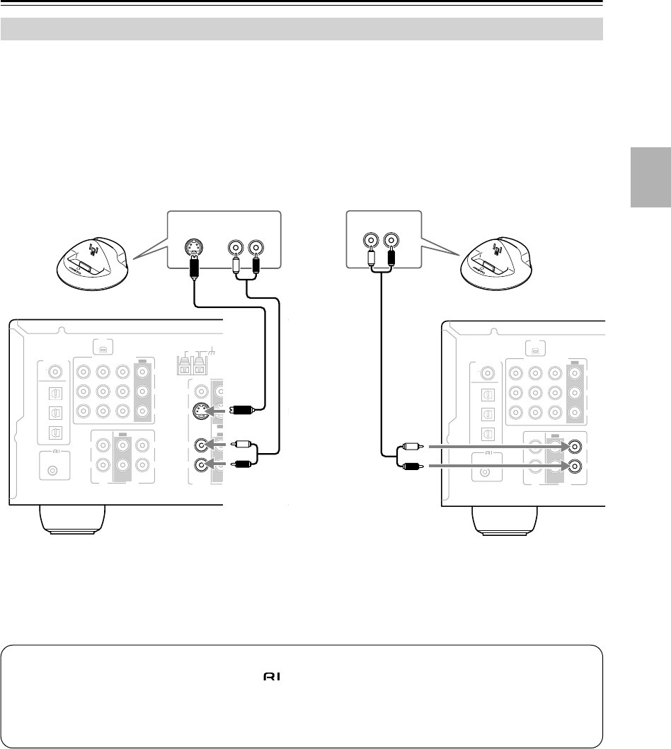
31
Connecting Your Components
—Continued
As of this printing, the Onkyo Remote Interactive Dock is the only HDD-compatible component available.
■
For HDD-compatible components that
support video
Connect your HDD-compatible component’s analog
audio output jacks and S-Video output jack to the AV
receiver’s VIDEO 2 IN L/R jacks and VIDEO 2 IN S
jack.
■
For HDD-compatible components that don’t
support video
Connect your HDD-compatible component’s analog
audio output jacks to the AV receiver’s TAPE IN L/R
jacks.
Connecting an HDD-compatible Component
COA
XIAL
REMOTE
CONTROL
OPTICAL
1
Y
PB
PR
2
3
DIGITAL IN
L
R
L
R
L
R
V
S
CD TAPE
XM ANTENNA
FM
AM 75
COMPONENT
VIDEO 2 IN
IN IN
OUT
OUT
IN IN
OUT
IN IN IN
OUT
VIDEO 1 IN DVD IN
VIDEO
VIDEO 2 VIDEO 1
VIDEO 2 VIDEO 1
D
DVD
MONITO
R
OUT
FRONT
SURROUN
D
AUDIO
OUT
LR
S VIDEO
OUT
COA
XIAL
REMOTE
CONTROL
OPTICAL
1
Y
PB
PR
2
3
DIGITAL IN
L
R
L
R
CD TAPE
XM
COMPONENT
VIDEO 2 IN
IN IN
OUT
OUT
VIDEO 1 IN DVD IN
VIDEO
AUDIO
OUT
LR
Notes:
• Connect the Remote Interactive Dock with an cable (see page 33).
• Set the Remote Interactive Dock’s RI MODE switch to HDD.
• Set the AV receiver’s Input Display to HDD (see page 35).
• Refer to the Remote Interactive Dock’s instruction manual.
HT-S790_En.book Page 31 Friday, February 17, 2006 3:28 PM
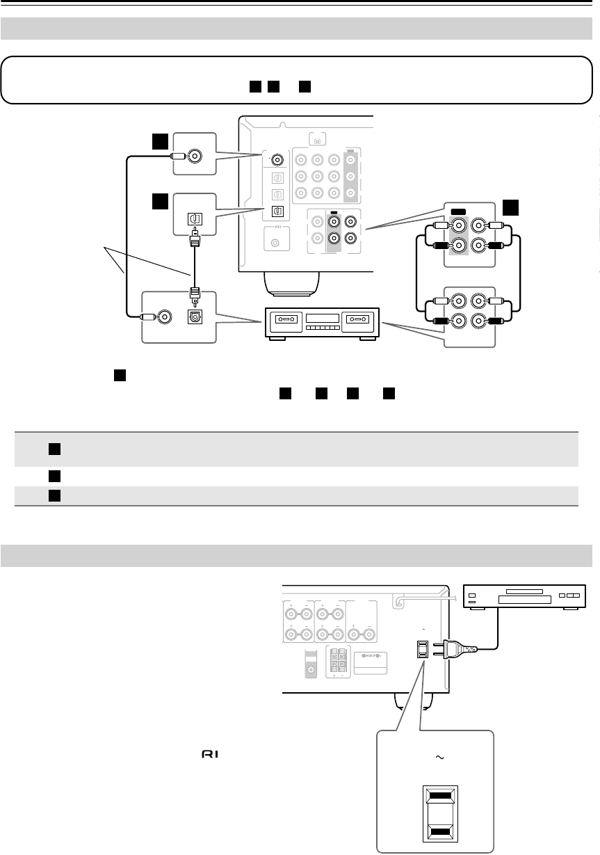
32
Connecting Your Components
—Continued
•With connection , you can listen via speaker set B.
•To connect the recorder digitally, use connections and , or and .
The AV receiver has an AC outlet on its rear panel for
connecting the power cord of another AV component.
The other component’s power switch can then be left in
the ON position so that it turns on or off when the AV
receiver is set to On or Standby.
Caution:
•Make sure that the capacity of the component that
you connect to the AC OUTLET does not exceed
the stated capacity (e.g., 100 W).
Notes:
•Onkyo components connected via should be
connected directly to a wall outlet, not the AV
receiver’s AC OUTLET.
• The socket type and capacity depends on the
country in which you purchased the AV receiver.
Connecting a Cassette, CDR, MiniDisc, or DAT Recorder
Connection AV receiver Signal flow Cassette/CDR/MD/DAT recorder
TAPE IN L/R
TAPE OUT L/R
⇐
⇒
Analog audio L/R output
Analog audio L/R input
DIGITAL IN COAXIAL
⇐
Digital coaxial output
DIGITAL IN OPTICAL 3
⇐
Digital optical output
COA
XIAL
REMOTE
CONTROL
OPTICAL
1
Y
PB
PR
2
3
DIGITAL IN
L
R
L
R
L
L
L
R
R
R
V
S
CD TAPE
XM ANTENNA
FM
AM 75
COMPONENT
VIDEO 2 IN
IN IN
OUT
OUT
IN IN
OUT
IN IN IN
OUT
VIDEO 1 IN DVD IN
VIDEO
VIDEO 2 VIDEO 1
VIDEO 2 VIDEO 1 DVD
DVD
MONITOR
OUT
SURROUND BACK
SPEAKERS
SURROUND
SPEAKERS
PRE OUT
SUB
WOOFER
SUB
WOOFER
FRONT
SURROUND
SURR BACK
CENTER
FRONT
SPEAKERS A
FR
O
SPEA
K
OUT
REC PLAY
IN OUT
L
R
L
R
IN
TAPE
L
R
OPTICAL
3
OPTICAL
OUT
DIGITAL IN
COAXIAL
COAXIAL
OUT
b
ca
Step 1:
Choose a connection that matches the recorder ( , , or ), and then make the connection.
a b c
Cassette recorder, CDR, etc.
Connect one or the
other
These connections
must be assigned
(see page 35)
a
a b a c
a
b
c
Connecting the Power Cord of Another Component
L
R
L
R
SURROUND
SPEAKERS
PRE OUT
SUB
WOOFER
FRONT
SPEAKERS A
FRONT
SPEAKERS B
AV RECEIVER
AC OUTLET
AC 120V
SWITCHED
TOTAL120W 1A MAX.
60Hz
CENTER
SPEAKER
AC OUTLET
AC 120V
SWITCHED
TOTAL 120W 1A MAX.
60Hz
HT-S790_En.book Page 32 Friday, February 17, 2006 3:28 PM
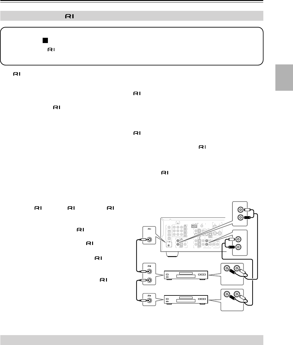
33
Connecting Your Components
—Continued
With (Remote Interactive), you can use the following special functions:
■
Auto Power On/Standby
When you start playback on a component connected via , if the AV receiver is on Standby, it will automatically
turn on and select that component as the input source. Similarly, when the AV receiver is set to Standby, all compo-
nents connected via will also go on Standby. This function will not work on components connected to an AC
OUTLET on the AV receiver.
■
Direct Change
When playback is started on a component connected via , the AV receiver automatically selects that component
as the input source. If your DVD player is connected to the AV receiver’s multichannel DVD input, you’ll need to
press the [MULTI CH] button to hear all channels (see page 37), as the Direct Change function only selects the
FRONT DVD IN jacks.
■
Remote Control
You can use the AV receiver’s remote controller to control your other -capable Onkyo components, pointing the
remote controller at the AV receiver’s remote control sensor instead of the component. You must enter the appropri-
ate remote control code first (page 59).
Notes:
• Use only cables for connections.
cables are supplied with Onkyo players (DVD,
CD, etc.).
• Some components have two jacks. You can
connect either one to the AV receiver. The other
jack is for connecting additional -capable
components.
• Connect only Onkyo components to jacks.
Connecting other manufacturer’s components
may cause a malfunction.
• Some components may not support all func-
tions. Refer to the manuals supplied with your
other Onkyo components.
• Connect the AV receiver’s and subwoofer’s power cord to a suitable wall outlet.
Notes:
•
Before connecting the power cord, connect all of your speakers and AV components.
•Turning on the AV receiver and subwoofer may cause a momentary power surge that might interfere with other
electrical equipment on the same circuit. If this is a problem, plug the AV receiver into a different branch circuit.
Connecting Onkyo Components
Connecting the Power Cord
Step 1: Make sure that each Onkyo component is connected to the AV receiver with an analog audio cable (con-
nection in the hookup examples) (see pages 24 to 32).
Step 2: Make the connection.
Step 3: If you’re using an MD, CDR, or HDD component, change the input Display (see page 35).
a
COA
XIAL
REMOTE
CONTROL
OPTICAL
1
Y
PB
PR
2
3
DIGITAL IN
L
R
L
R
L
L
R
R
V
S
CD TAPE
XM ANTENNA
FM
AM 75
COMPONENT
VIDEO 2 IN
IN IN
OUT
OUT
IN IN
OUT
IN IN IN
OUT
VIDEO 1 IN DVD IN
VIDEO
VIDEO 2 VIDEO 1
VIDEO 2 VIDEO 1 DVD
DVD
MONITOR
OUT
SURROUND BACK
SPEAKERS
SUB
WOOFER
FRONT
SURROUND
SURR BACK
CENTER
LR
FRONT
DVD
L
R
IN
CD
L
R
REMOTE
CONTROL
ANALOG
AUDIO OUT
LR
ANALOG
AUDIO OUT
e.g., CD player
e.g., DVD player
HT-S790_En.book Page 33 Friday, February 17, 2006 3:28 PM
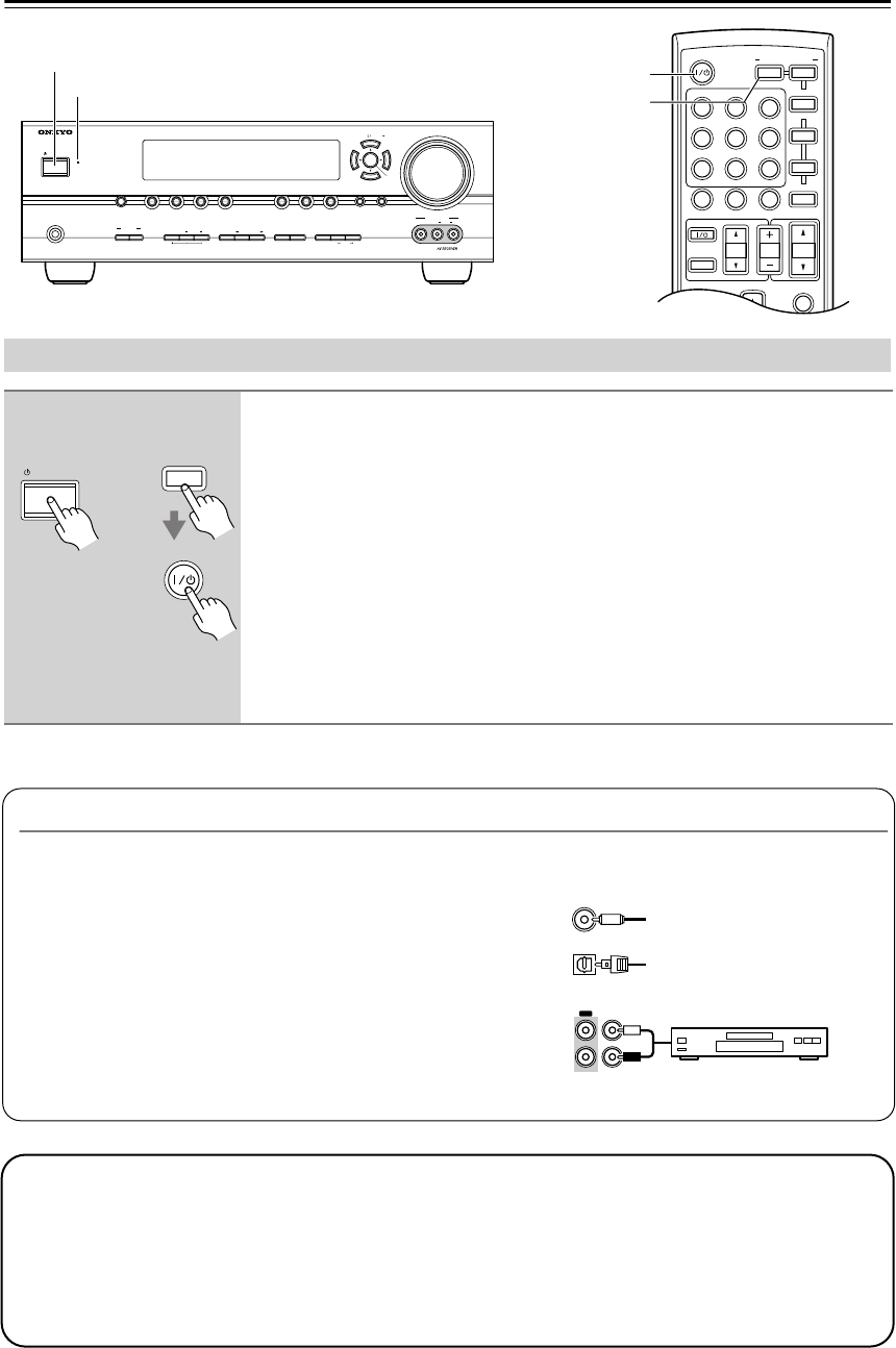
34
Turning On the AV Receiver
MASTER VOLUME
VIDEO
STANDBY
TONE DISPLAYSTEREO DIMMER MEMORY
DIGITAL
INPUT
TUNING
MODE
AB
SPEAKERS
TUNERTAPE
VIDEO 3VIDEO 2VIDEO 1
VCR
DVDMULTI CH C
DSETUPRETURN
CLEAR
LISTENING MODE
AUDIOLR
VIDEO 3 INPUT
STANDBY/ON
PHONES
TUNING PRESET
ENTER
STANDBY/ON
MUTING
PREVIOUS
MENU
GUIDE
TOP MENU
SP A
/
B
--
/
---
TAPE
M
D/CDR
HDD
CABLE
ON/STANDBY
DIMMER
ENT
D TUN
SLEEP
10 11 12
INPUT SELECTOR
REMOTE MODE
V1V2V3
C
DTAPE TUNER
DVD
MULTI CH
TV VOL
VOL
SAT
VCR
TV
DVD
RECEIVER
C
D
INPUT
+10
0
CLR
123
456
789
CH
DISC
ALBUM
RECEIVER
ON/STANDBY
STANDBY indicator
Turning On and Standby
1
Press the [STANDBY/ON] button.
Alternatively, press the remote controller’s [RECEIVER] button, followed
by the [ON/STANDBY] button.
The AV receiver comes on, the display lights up, and the STANDBY indicator goes off.
To turn the AV receiver off, press the [STANDBY/ON] button, or press the remote
controller’s [ON/STANDBY] button. The AV receiver will enter Standby mode. To
prevent any loud surprises when you next turn on the AV receiver, always turn down
the volume before you turn it off.
To turn on the subwoofer, press its [POWER] switch to the ON position
(not North
American models).
STANDBY/ON
ON/STANDBY
Remote
controller
AV receiver
or
RECEIVER
Smooth Operation in a Few Easy Steps
To ensure smooth operation, here’s a few easy steps to help you configure the AV receiver before you use it for the
very first time. These settings only need to be made once.
■Have you connected a component to a digital audio input?
If you have, see “Assigning Digital Inputs to Input Sources” on
page 35.
■Have you connected an Onkyo MD recorder, CD recorder,
or next generation HDD-compatible component?
If you have, see “Changing the Input Display” on page 35.
OPT1
COAX
OUT IN
TAPE CD recorder, MD recorder,
RI Dock, etc.
Testing the speakers
To test that all of the speakers are working properly, press the remote controller’s [TEST TONE] button. The
test tone will be output by each speaker in turn and the name of each speaker will appear on the display. To turn off
the test tone, press the [TEST TONE] button again.
•If the test tone is not produced by a speaker, or it’s produced by a speaker other than that shown on the display,
you may have wired the speakers incorrectly and you should check your connections (see page 19).
•Testing cannot be performed while speaker set B is on or a pair of headphones is connected.
HT-S790_En.book Page 34 Friday, February 17, 2006 3:28 PM
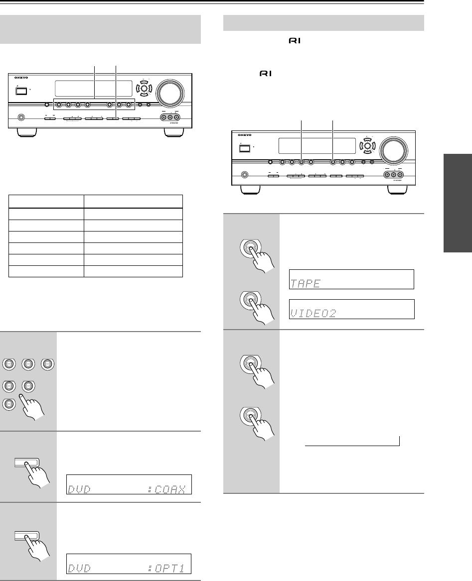
35
First Time Setup
To enjoy Dolby Digital and DTS, you must connect your
DVD player to the AV receiver digitally (coaxial or opti-
cal).
Here are the default assignments.
With this function, you can change the digital inputs
assign. If, for example, you connect your DVD player to
the DIGITAL IN OPTICAL 1 input (OPT1), you’ll need
to assign it to the DVD input source, as follows.
Note:
Make sure that components connected digitally are con-
figured to output digital audio. Refer to the relevant man-
uals.
If you connect an -capable Onkyo MiniDisc
recorder, CD recorder or next generation HDD-compat-
ible component to the TAPE IN/OUT or VIDEO 2 IN
jacks, for to work properly, you must change this
setting.
This setting can only be changed on the AV receiver.
Note:
HDD can be selected for the TAPE input selector or
VIDEO 2 input selector, but not both at the same time.
Assigning Digital Inputs to Input
Sources
Input selector Default assignment
DVD COAX
VIDEO 1 OPT 1
VIDEO 2 OPT 2
VIDEO 3 - - - -
TAPE - - - -
CD OPT 3
1
Press the input selector button
for the input source that you want
to assign.
(Digital inputs cannot be assigned to
the TUNER input source.)
2
Press the [DIGITAL INPUT]
button.
The current assignment appears.
3
Press the [DIGITAL INPUT] but-
ton repeatedly to select COAX,
OPT1, OPT2, OPT3, or “– – – –”
(analog).
MASTER VOLUME
VIDEO
STANDBY
TONE DISPLAYSTEREO DIMMER MEMORY
DIGITAL
INPUT
TUNING
MODEAB
SPEAKERS
TUNERTAPE
VIDEO 3VIDEO 2VIDEO 1
VCR
DVDMULTI CH C
DSETUPRETURN
CLEAR
LISTENING MODE
AUDIOLR
VIDEO 3 INPUT
STANDBY/ON
PHONES
TUNING PRESET
ENTER
1 2, 3
TAPE
C
D
VIDEO 3
DVD VIDEO 1
VCR
VIDEO 2
DIGITAL
INPUT
DIGITAL
INPUT
Changing the Input Display
1
Press the [TAPE] or [VIDEO 2]
input selector button so that
“TAPE” or “VIDEO2” appears on
the display.
2
Press and hold down the [TAPE]
or [VIDEO 2] input selector but-
ton (about 3 seconds) to change
the setting.
Repeat this step to select MD, CDR, or
HDD.
For the TAPE input selector, the setting
changes in this order:
TAPE
→
MD
→
CDR
→
HDD
For the VIDEO 2 input selector, the set-
ting changes in this order:
VIDEO 2
↔
HDD
MASTER VOLUME
VIDEO
STANDBY
TONE DISPLAYSTEREO DIMMER MEMORY
DIGITAL
INPUT
TUNING
MODE
AB
SPEAKERS
TUNERTAPE
VIDEO 3VIDEO 2VIDEO 1
VCR
DVDMULTI CH C
DSETUPRETURN
CLEAR
LISTENING MODE
AUDIOLR
VIDEO 3 INPUT
STANDBY/ON
PHONES
TUNING PRESET
ENTER
1, 21, 2
TAPE
VIDEO 2
or
TAPE
VIDEO 2
or
→
HT-S790_En.book Page 35 Friday, February 17, 2006 3:28 PM
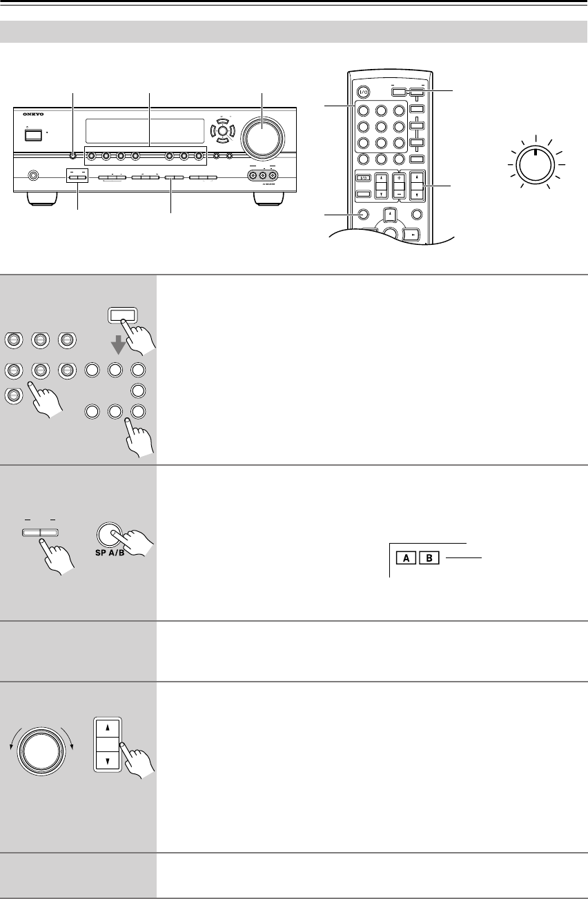
36
Playing Your AV Components
Basic AV Receiver Operation
MASTER VOLUME
VIDEO
STANDBY
TONE DISPLAYSTEREO DIMMER MEMORY
DIGITAL
INPUT
TUNING
MODE
AB
SPEAKERS
TUNERTAPE
VIDEO 3VIDEO 2VIDEO 1
VCR
DVDMULTI CH C
DSETUPRETURN
CLEAR
LISTENING MODE
AUDIOLR
VIDEO 3 INPUT
STANDBY/ON
PHONES
TUNING PRESET
ENTER
DISPLAY
MULTI CH
1
2
4
MUTING
PREVIOUS
MENU
GUIDE
TOP MENU
SP A
/
B
PLAYLIST/CAT PLAYLIST/CAT
--
/
---
TAPE
M
D/CDR
HDD
CABLE
ON/STANDBY
DIMMER
ENT
D TUN
SLEEP
10 11 12
INPUT SELECTOR
REMOTE MODE
V1V2V3
C
DTAPE TUNER
DVD
MULTI CH
TV VOL
VOL
SAT
VCR
TV
DVD
RECEIVER
C
D
INPUT
+10
0
CLR
123
456
789
ENTER
CH
DISC
ALBUM
4
1
1
2
OUTPUT LEVEL
MAX
MIN
Subwoofer’s
rear panel
1
Use the AV receiver’s input selector buttons to select the input source.
To select the input source with the remote controller, press the
[RECEIVER] REMOTE MODE button, and then use the INPUT SELECTOR
buttons.
On the remote controller, the [V1], [V2], and [V3] buttons select the VIDEO 1,
VIDEO 2, and VIDEO 3 input sources respectively.
2
To turn the speakers on or off, use the AV receiver’s SPEAKERS [A] and
[B] buttons, or use the remote controller’s [SP A/B] button.
Pressing the remote controller’s [SP A/B] button cycles through the following settings:
Speaker Set A
→
Speaker Set A&B
→
Speaker Set B
→
Off.
Note that while speaker set B is on,
speaker set A is reduced to 5.1-channel
playback.
See page 5 for more information about speaker sets A and B.
3
Start playback on the source component.
To watch a DVD or other video source, on your TV, select the video input that’s con-
nected to the AV receiver’s MONITOR OUT jack.
4
To adjust the volume, use the MASTER VOLUME control, or the remote
controller’s [VOL] button.
The volume can be set to MIN, 1 through 79, or MAX. Since the AV receiver is
designed for home theater enjoyment, it has a wide volume range for precise adjust-
ment.
To set the level of the subwoofer, use the OUTPUT LEVEL control.
Because our ears are less sensitive to very low bass sounds, there’s a temptation to set
the level of the subwoofer too high. As a rule of thumb, set the subwoofer level to what
you think is the optimal level, and then back it off slightly.
5
Select a suitable listening mode and enjoy!
See “Using the Listening Modes” on page 46.
RECEIVER
TAPE TUNER
C
D
VIDEO 3
DVD VIDEO 1
VCR
VIDEO 2
V1V2V3
C
DTAPE TUNER
DVD
123
6
789
Remote
controller
AV receiver
AB
SPEAKERS
Remote
controller
AV receiver
Indicators
VOL
MASTER VOLUME
Remote
controller
AV receiver
HT-S790_En.book Page 36 Friday, February 17, 2006 3:28 PM
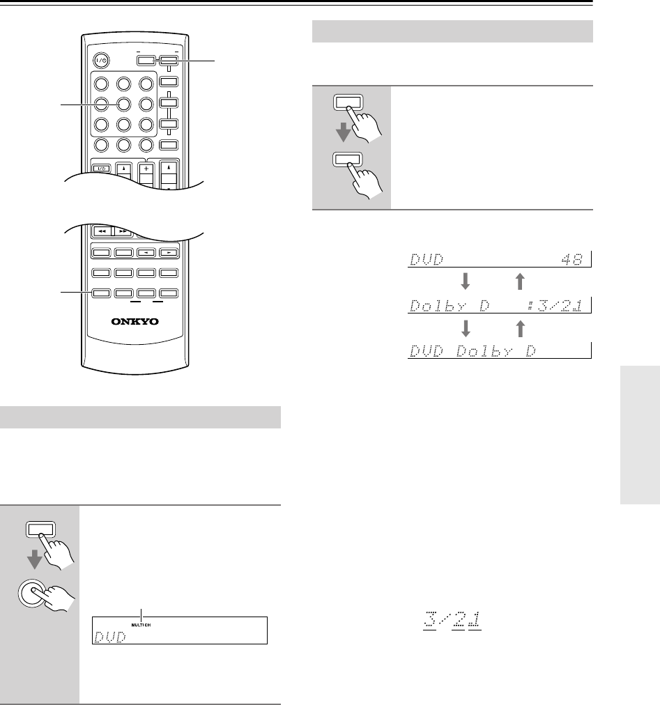
37
Playing Your AV Components
—Continued
The multichannel DVD input is for connecting a compo-
nent with a 7.1-channel analog audio output, such as a
DVD-Audio or SACD-capable DVD player, or an
MPEG decoder. See page 26 for hookup information.
Note:
• While the multichannel DVD input is selected, the
Speaker Configuration settings on page 54 are
ignored, and signals from the multichannel input are
fed to the speakers as they are.
You can display various information about the current
input source as follows.
The following information can typically be displayed:
*1 When AM or FM radio is used, the band, preset num-
ber, and frequency are displayed.
*2 If the input signal is analog, or AM or FM radio is
selected, no format information is displayed. If the
input signal is PCM, the sampling frequency is dis-
played. If the input signal is digital but not PCM, the
signal format is displayed. Information is displayed
for about 3 seconds, then the previous display reap-
pears.
Note:
•The listening mode is displayed only when speaker set
A is on.
Interpreting Surround Channel Information
A: The number of front channels (front left, front right,
and center).
B: The number of surround channels (surround left and
surround right). If there’s surround back channel
information, this number will be 3.
C: LFE channel for subwoofer (1 means yes).
Using the Multichannel DVD Input
Press the [RECEIVER] REMOTE
MODE button, followed by the
[MULTI CH] button.
The MULTI CH indicator appears on
the display.
Audio from the multichannel DVD
input will now be used for the DVD
input source.
RANDOM
SUBTITLE
PLAY MODE
AUDIO REPEAT
RC-649M
--
/
---
TAPE
M
D/CDR
HDD
CABLE
ON/STANDBY
DIMMER
ENT
D TUN
SLEEP
10 11 12
INPUT SELECTOR
HDDDVD
VCR
REMOTE MODE
V
1
V
2
V
3
C
DTAPE TUNER
DVD
MULTI CH
LISTENING MODE
TV
DISPLAY
TEST
TONE
CH SEL
OR-EQ
SURROUND
STEREO
CINE FLTR
LEVEL
+
LEVEL
-
L NIGHT
VOL
VOL
SAT
VCR
TV
DVD
RECEIVER
C
D
INPUT
+10
0
CLR
123
456
789
CH
DISC
ALBUM
DISPLAY
RECEIVER
MULTI CH
RECEIVER
MULTI CH
MULTI CH indicator
Displaying Source Information
Press the [RECEIVER] REMOTE
MODE button, and then press the
[DISPLAY] button repeatedly to
cycle through the available infor-
mation.
DISPLAY
RECEIVER
Input source &
volume*1
Signal format*2
or sampling
frequency
Input source &
listening mode
ABC
HT-S790_En.book Page 37 Friday, February 17, 2006 3:28 PM
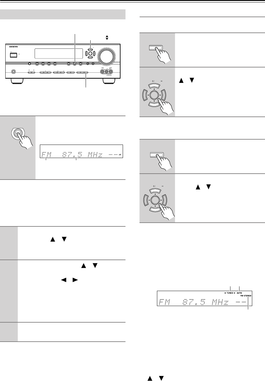
38
Listening to the Radio
With the built-in tuner, you can enjoy AM and FM radio
stations.
■
AM Frequency Step Setup (not North America)
You must specify the AM frequency step used in your
area. Note that when this setting is changed, all radio
presets are deleted.
Tuning into AM/FM Radio Stations
■
Auto Tuning Mode
■
Manual Tuning Mode
The American model changes FM frequency in 0.2 MHz
steps, 10 kHz steps for AM. For other models it’s
0.05 MHz steps for FM and 9 kHz (or 10 kHz) steps for
AM.
When tuned into a station, the TUNED indicator
appears. When tuned into a stereo FM station, the FM
STEREO indicator also appears.
Tuning into Weak FM Stereo Stations
If the signal from a stereo FM station is weak, it may be
impossible to get good reception. In this case, switch to
Manual Tuning mode and listen to the station in mono.
Note:
•You can also use the remote controller’s Up and Down
[ ]/[ ] buttons to tune the radio.
Listening to AM/FM stations
1
Use the [TUNER] input selector
button to select AM or FM.
In this example, FM has been selected.
(Actual display depends on country.)
1
Press the [SETUP] button, use the Up
and Down [ ]/[ ] buttons to select “0.
Hardware Setup,” and then press
[ENTER].
2
Use the Up and Down [ ]/[ ] buttons
to select “AM Freq,” and then use the
Left and Right [ ]/[ ] buttons to
select:
10 kHz:
Select if 10 kHz steps are used in your
area.
9 kHz:
Select if 9 kHz steps are used in your
area.
3
Press the [SETUP] button.
Setup closes.
MASTER VOLUME
VIDEO
STANDBY
TONE DISPLAYSTEREO DIMMER MEMORY
DIGITAL
INPUT
TUNING
MODEAB
SPEAKERS
TUNERTAPE
VIDEO 3VIDEO 2VIDEO 1
VCR
DVDMULTI CH C
DSETUPRETURN
CLEAR
LISTENING MODE
AUDIOLR
VIDEO 3 INPUT
STANDBY/ON
PHONES
TUNING PRESET
ENTER
TUNING
TUNER
TUNING MODE
TUNER
Band Frequency
1
Press the [TUNING MODE] button
so that the AUTO indicator
appears on the display.
2
Press the TUNING Up or Down
[ ]/[ ] button.
Searching stops when a station is
found.
1
Press the [TUNING MODE] button
so that the AUTO indicator disap-
pears from the display.
2
Press and hold the TUNING Up or
Down [ ]/[ ] button.
The frequency stops changing when
you release the button.
Press the buttons repeatedly to change
the frequency one step at a time.
TUNING
MODE
TUNING PRESET
TUNING
MODE
TUNING PRESET
AUTOTUNED
FM STEREO
HT-S790_En.book Page 38 Friday, February 17, 2006 3:28 PM
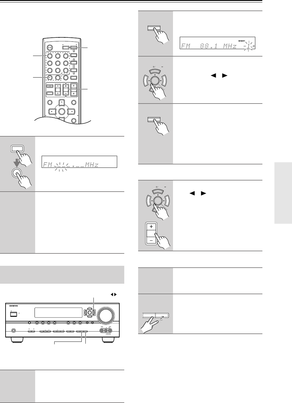
39
Listening to the Radio
—Continued
■
Tuning into Stations by Frequency
You can tune into AM and FM stations directly by enter-
ing the appropriate frequency.
You can store a combination of up to 40 of your favorite
AM/FM radio stations and XM channels as presets.
■
Selecting Presets
■
Deleting Presets
1
Press the [RECEIVER] button,
followed by the [D TUN] button.
(Actual display depends on country.)
The [RECEIVER] button flashes.
2
Within 8 seconds, use the num-
ber buttons to enter the fre-
quency of the radio station.
For example, to tune to 87.5 (FM),
press 8, 7, 5.
Note
: While the [RECEIVER] button is
flashing, the input source cannot be
changed by using the remote controller.
Presetting AM/FM Stations and
XM Channels
1
Tune into the AM/FM station or
XM channel that you want to
store as a preset.
See page 40 to select XM channels.
MUTING
PREVIOUS
MENU
GUIDE
TOP MENU
SP A
/
B
SETUPRETURN
PLAYLIST/CAT PLAYLIST/CAT
--
/
---
TAPE
M
D/CDR
HDD
CABLE
ON/STANDBY
DIMMER
ENT
D TUN
SLEEP
10 11 12
INPUT SELECTOR
REMOTE MODE
V
1
V
2
V
3
C
DTAPE TUNER
DVD
MULTI CH
TV VOL
VOL
SAT
VCR
TV
DVD
RECEIVER
C
D
INPUT
+10
0
CLR
123
456
789
ENTER
CH
DISC
ALBUM CH +/–
RECEIVER
D TUN
Number
buttons
RECEIVER
D TUN
MASTER VOLUME
VIDEO
STANDBY
TONE DISPLAYSTEREO DIMMER MEMORY
DIGITAL
INPUT
TUNING
MODEAB
SPEAKERS
TUNERTAPE
VIDEO 3VIDEO 2VIDEO 1
VCR
DVDMULTI CH C
DSETUPRETURN
CLEAR
LISTENING MODE
AUDIOLR
VIDEO 3 INPUT
STANDBY/ON
PHONES
TUNING PRESET
ENTER
MEMORY TUNING MODE
PRESET
2
Press the [MEMORY] button.
The MEMORY indicator appears and
the preset number flashes.
3
While the MEMORY indicator is
displayed (about 8 seconds), use
the PRESET [ ]/[ ] buttons to
select a preset from 1 through 40.
4
Press the [MEMORY] button
again to store the station or
channel.
The station or channel is stored and the
preset number stops flashing.
Repeat this procedure for all of your
favorite AM/FM radio stations and XM
channels.
1
To select a preset, use the PRE-
SET [ ]/[ ] buttons, or the
remote controller’s CH [+/–] but-
ton.
1
Select the preset that you want to
delete.
See the previous section.
2
While holding down the [MEM-
ORY] button, press the
[TUNING MODE] button.
The preset is deleted and its number
disappears from the display.
MEMORY
TUNING PRESET
ENTER
MEMORY
TUNING PRESET
ENTE
R
CH
DISC
ALBUM
MEMORY
TUNING
MODE
CLEAR
HT-S790_En.book Page 39 Friday, February 17, 2006 3:28 PM
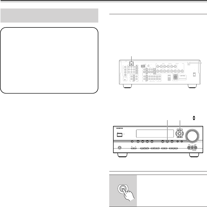
40
Listening to the Radio
—Continued
Note:
Hardware and required basic monthly subscription sold
separately. Premium Channels available at additional
monthly cost. Installation costs and other fees and taxes,
including a one-time activation fee may apply. Subscrip-
tion fee is consumer only. All fees and programming
subject to change.
About XM Radio:
There is a world beyond AM and FM. It is XM Satellite
Radio. XM offers more than 160 digital channels of
audio entertainment, including 100% commercial-free
music channels, in the top markets in the U.S.
Channels with frequent explicit language are indicated
with an XL. Channel blocking is available for XM radio
receivers by calling 1-800-XMRADIO.
About XM Canada:
XM Canada offers the most commercial-free music –
and engaging talk show programs. XM Canada creates
original content that reflects our unique Canadian culture
and broadcasts it throughout North America.
Canadian Satellite Radio Inc. offers its satellite radio ser-
vice and operates under the XM Canada™ brand. XM
Canada has an exclusive Canadian licence from XM Sat-
ellite Radio Inc.
For more information about XM Canada, visit
www.xmradio.ca or call 1-877-GET-XMSR
A warning against reverse engineering:
It is prohibited to copy, decompile, disassemble, reverse
engineer, or manipulate any technology incorporated in
receivers compatible with the XM Satellite Radio sys-
tem. Furthermore, the AMBE
®
voice compression soft-
ware included in this product is protected by intellectual
property rights including patent rights, copyrights, and
trade secrets of Digital Voice Systems, Inc. The user of
this or any other software contained in an XM Radio is
explicitly prohibited from attempting to copy, decom-
pile, reverse engineer, or disassemble the object code, or
in any other way convert the object code into human-
readable form. The software is licensed solely for use
within this product.
Connecting the XM Passport System
The XM Passport System is sold separately. You can pur-
chase the
XM Passport System
from the XM Web site at:
http://www.xmradio.com (U.S.A.)
http://www.xmradio.ca (Canada)
Connect the Passport System to the XM antenna jack on
the rear panel.
Put the XM Passport System by a southerly facing win-
dow, with nothing obstructing its path to the sky.
Selecting XM Satellite Radio
Listening to XM Satellite Radio
®
(North American Models Only)
Important XM Radio Information
To receive XM Radio on this receiver you need to
purchase an optional XM Passport System and sub-
scribe to XM’s paid programming. Please note that
XM is currently only licensed to provide service to
the contiguous 48 United States (not available in
Alaska and Hawaii) and portions of Canada. XM
Radio service is not currently available in Mexico or
any other region outside the continental U.S. and
portions of Canada. For updates on service availabil-
ity please visit XM's website at
http://www.xmradio.com or http://www.xmradio.ca
1
Press the [TUNER] input selector
button repeatedly to select XM.
If “CHECK ANTENNA” appears on
the display, make sure the XM Passport
System is connected properly.
COA
XIAL
REMOTE
CONTROL
OPTICAL
1
Y
PB
PR
2
3
DIGITAL IN
L
R
L
R
L
L
L
R
R
L
R
R
V
S
CD TAPE
XM ANTENNA
FM
AM 75
COMPONENT
VIDEO 2 IN
IN IN
OUT
OUT
IN IN
OUT
IN IN IN
OUT
VIDEO 1 IN DVD IN
VIDEO
VIDEO 2 VIDEO 1
VIDEO 2 VIDEO 1 DVD
DVD
MONITOR
OUT
SURROUND BACK
SPEAKERS
SURROUND
SPEAKERS
PRE OUT
SUB
WOOFER
SUB
WOOFER
FRONT
SURROUND
SURR BACK
CENTER
FRONT
SPEAKERS A
FRONT
SPEAKERS B
AV RECEIVER
AC OUTLET
AC 120V
SWITCHED
TOTAL120W 1A MAX.
60Hz
CENTER
SPEAKER
XM antenna jack
MASTER VOLUME
VIDEO
STANDBY
TONE DISPLAYSTEREO DIMMER MEMORY
DIGITAL
INPUT
TUNING
MODEAB
SPEAKERS
TUNERTAPE
VIDEO 3VIDEO 2VIDEO 1
VCR
DVDMULTI CH C
DSETUPRETURN
CLEAR
LISTENING MODE
AUDIOLR
VIDEO 3 INPUT
STANDBY/ON
PHONES
TUNING PRESET
ENTER
TUNINGTUNER
TUNER
HT-S790_En.book Page 40 Friday, February 17, 2006 3:28 PM
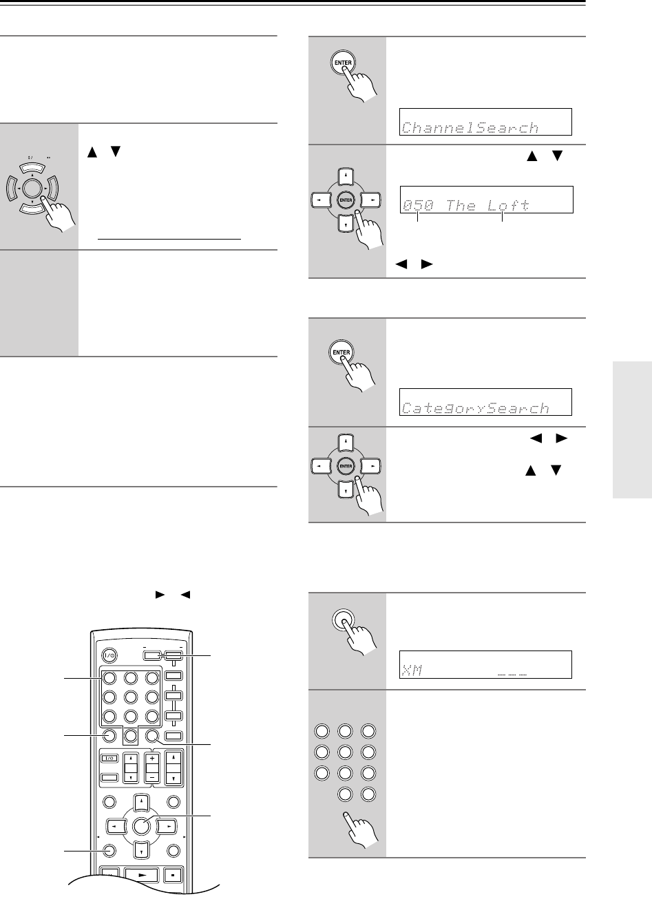
41
Listening to the Radio
—Continued
Signing Up for XM Satellite Radio
Before you can use XM Satellite Radio, you must first
sign up for an account. You’ll need a major credit card
and your
XM Satellite Radio ID,
which you can get from
the AV receiver, as explained below, or from the Passport
System package and itself.
Notes:
• Channel 0 cannot be selected in Category Search
mode. You must select Channel Search mode (see
page 41).
• The following letters are not used in XM Satellite
Radio IDs: I, O, S, F.
Selecting XM Radio Channels
There are three ways to select XM radio channels:
•
Channel Search mode:
select any channel.
•
Category Search mode:
select channels by category.
•
Direct tuning:
enter channel number.
Note:
You can’t select Channel Search or Category Search
mode, while the Tuning Arrow indicators are
flashing, as tuning is in progress.
■
Channel Search Mode
■
Category Search Mode
■
Direct Tuning
You can select an XM radio channel directly by entering
its number.
1
Use the TUNING Up and Down
[ ]/[ ] buttons to select
channel 0.
Your XM Satellite Radio ID number is
displayed. Write it below.
ID
2
To sign up, go to:
http://activate.xmradio.com
Or call: 1-800-967-2346
For XM Canada, go to:
http://xmradio.ca
Or call: 1-877-GET-XMSR
TUNING PRESET
MUTING
PREVIOUS
MENU
GUIDE
TOP MENU
SP A
/
B
SETUPRETURN
PLAYLIST/CAT PLAYLIST/CAT
--
/
---
TAPE
M
D/CDR
HDD
CABLE
ON/STANDBY
DIMMER
ENT
D TUN
SLEEP
10 11 12
INPUT SELECTOR
REMOTE MODE
V1V2V3
C
DTAPE TUNER
DVD
MULTI CH
TV VOL
VOL
SAT
VCR
TV
DVD
RECEIVER
C
D
INPUT
+10
0
CLR
123
456
789
ENTER
CH
DISC
ALBUM
ENTER
RECEIVER
RETURN
ENT
D TUN
Number
buttons
1
Press the [RECEIVER] button,
followed by the [ENTER] button
to select “Channel Search”
mode.
2
Use the Up and Down [ ]/[ ]
buttons to select a channel.
You can also use the Left and Right
[ ]/[ ] buttons to select a category.
1
Press the [RECEIVER] button,
followed by the [ENTER] button
to select “Category Search”
mode.
2
Use the Left and Right [ ]/[ ]
buttons to select a category, and
use the Up and Down [ ]/[ ]
buttons to select a channel in
that category.
1
Press the [RECEIVER] button,
followed by the [D TUN] button.
The [RECEIVER] button flashes.
2
Within 8 seconds, use the num-
ber buttons to enter the channel
number.
The channel is selected.
For example, to select channel #20,
press 0, 2, 0, or 2, 0, [ENT].
Note
: While the [RECEIVER] button is
flashing, the input source cannot be
changed by using the remote controller.
Channel nameChannel number
D TUN
DIMMER
ENT
SLEEP
11 12
V1V2V3
C
DTAPE TUNER
DVD
MULTI CH
0
CLR
123
456
789
HT-S790_En.book Page 41 Friday, February 17, 2006 3:28 PM
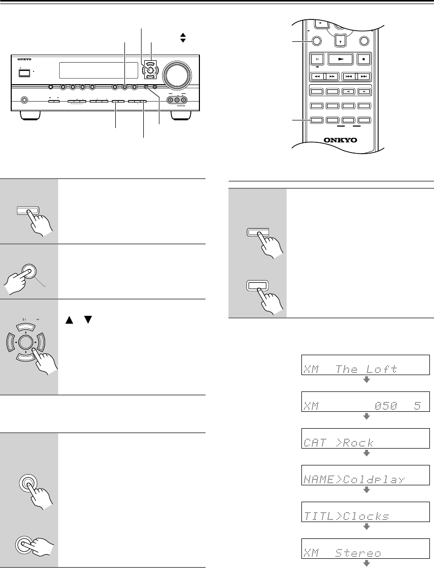
42
Listening to the Radio
—Continued
Selecting XM Channels from the Front Panel:
Selecting the Previous Channel:
Displaying XM Radio Information
The following information can be displayed:
Notes:
• If the category, artist, or song title is not available,
“- - -” will be displayed instead.
•The listening mode is displayed only when speaker set
A is on.
1
Press the [TUNING MODE] button
to select “Channel Search” or
“Category Search” mode.
2
Press the [ENTER] button repeat-
edly to select a category.
3
Use the TUNING Up and Down
[]/[ ] buttons to select a chan-
nel.
In Channel Search mode, you can
select any channel.
In Category Search mode, you can only
select channels from the currently
selected category.
1
To listen to the previously
selected XM channel, press the
[RETURN] button.
MASTER VOLUME
VIDEO
STANDBY
TONE DISPLAYSTEREO DIMMER MEMORY
DIGITAL
INPUT
TUNING
MODEAB
SPEAKERS
TUNERTAPE
VIDEO 3VIDEO 2VIDEO 1
VCR
DVDMULTI CH C
DSETUPRETURN
CLEAR
LISTENING MODE
AUDIOLR
VIDEO 3 INPUT
STANDBY/ON
PHONES
TUNING PRESET
ENTER
RETURN
TUNING MODE
DISPLAY
TUNINGTUNER
ENTER
TUNING
MODE
ENTER
TUNING PRESET
RETURN
RETURN
Remote
controller
AV receiver
1
Press the [DISPLAY] button
repeatedly to cycle through the
available information.
SETUPRETURN
PLAYLIST/CAT PLAYLIST/CAT
RANDOM
SUBTITLE
PLAY MODE
AUDIO REPEAT
RC-649M
HDDDVDVCR
LISTENING MODE
DISPLAY
TEST
TONE
CH SEL
SURROUND
STEREO
CINE FLTR
LEVEL
+
LEVEL
-
L NIGHT
OR-EQ
SAT
ENTER
RETURN
DISPLAY
DISPLAY
DISPLAY
Remote
controller
AV receiver
Channel name
Channel number
& preset number
Category
Artist
Song title
Listening mode
HT-S790_En.book Page 42 Friday, February 17, 2006 3:28 PM
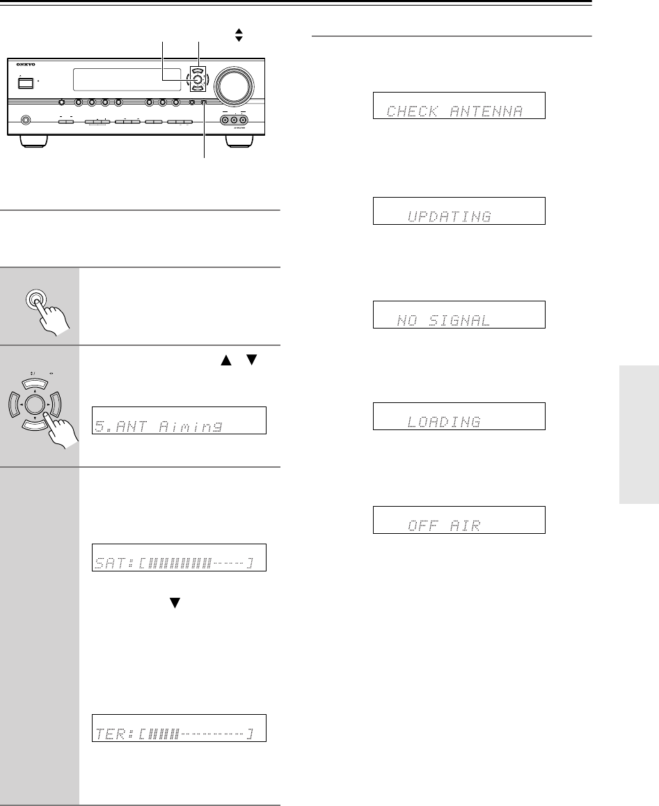
43
Listening to the Radio
—Continued
Positioning the XM Passport System
You can check the signal strength of the XM radio signal
and adjust the position of the XM Passport System
accordingly.
XM Radio Messages
The following messages may appear while using XM
radio.
The XM Passport System is not connected properly.
Check the connection.
The XM user encryption code is being updated. Please
wait.
The signal is too weak. Check the XM Passport System
connection and reposition it for the best reception.
The AV receiver is tuning or decoding audio or text data.
Please wait.
The XM channel you selected is not currently broadcast-
ing. Select another channel.
1
On the AV receiver, press the
[SETUP] button.
2
Use the Up and Down [ ]/[ ]
buttons to select “5. ANT Aim-
ing,” and then press [ENTER].
3
Adjust the position of the XM
Passport System so that the SAT
signal strength bar is as long as
possible.
If you can’t receive a satellite signal,
press the Down [ ] button to display
the terrestrial (TER) signal strength
meter and adjust your XM Passport
System so that the bar is as long as pos-
sible.
Terrestrial
signals are only available in
certain areas.
So long as the signal strength is good,
you can enjoy XM Radio by using
either satellite or terrestrial reception.
MASTER VOLUME
VIDEO
STANDBY
TONE DISPLAYSTEREO DIMMER MEMORY
DIGITAL
INPUT
TUNING
MODEAB
SPEAKERS
TUNERTAPE
VIDEO 3VIDEO 2VIDEO 1
VCR
DVDMULTI CH C
DSETUPRETURN
CLEAR
LISTENING MODE
AUDIOLR
VIDEO 3 INPUT
STANDBY/ON
PHONES
TUNING PRESET
ENTER
SETUP
TUNINGENTER
SETUP
TUNING PRESET
HT-S790_En.book Page 43 Friday, February 17, 2006 3:28 PM
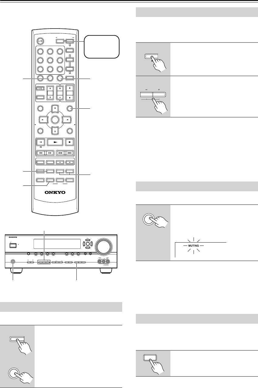
44
Common Functions
This section explains functions that can be used with any
input source.
You can adjust the brightness of the display.
You can adjust the bass and treble for the front speakers,
except when the Direct or Pure Audio (not North Amer-
ican models) listening mode is selected.
■
Bass
You can boost or cut low-frequency sounds output by the
front speakers from –10 dB to +10 dB in 2 dB steps.
■
Treble
You can boost or cut high-frequency sounds output by
the front speakers from –10 dB to +10 dB in 2 dB steps.
You can temporarily mute the output of the AV receiver.
To unmute the AV receiver,
press the remote control-
ler’s [MUTING] button again, or adjust the volume. The
output is unmuted and the MUTING indicator goes off.
Muting is cancelled when the AV receiver is set to
Standby.
When using the HT-R540 with the speakers included in
this Package, by turning on the OptiResponse equalizer,
you can enjoy a powerful sound with movies or music.
Setting the Display Brightness
Press the [DIMMER] button
repeatedly to select: dim, dim-
mer, or normal brightness.
MUTING
PREVIOUS
MENU
GUIDE
TOP MENU
SP A
/
B
SETUPRETURN
PLAYLIST/CAT PLAYLIST/CAT
RANDOM
SUBTITLE
PLAY MODE
AUDIO REPEAT
RC-649M
--
/
---
TAPE
M
D/CDR
HDD
CABLE
ON/STANDBY
DIMMER
ENT
D TUN
SLEEP
10 11 12
INPUT SELECTOR
HDDDVDVCR
REMOTE MODE
V1V2V3
C
DTAPE TUNER
DVD
MULTI CH
LISTENING MODE
TV
DISPLAY
TEST
TONE
CH SEL
OR-EQ
SURROUND
STEREO
CINE FLTR
LEVEL
+
LEVEL
-
L NIGHT
VOL
VOL
SAT
VCR
TV
DVD
RECEIVER
C
D
INPUT
+10
0
CLR
123
456
789
ENTER
CH
DISC
ALBUM
MUTING
CH SEL
OR-EQ
LEVEL – +
SLEEP
DIMMER
MASTER VOLUME
VIDEO
STANDBY
TONE DISPLAYSTEREO DIMMER MEMORY
DIGITAL
INPUT
TUNING
MODEAB
SPEAKERS
TUNERTAPE
VIDEO 3VIDEO 2VIDEO 1
VCR
DVDMULTI CH C
DSETUPRETURN
CLEAR
LISTENING MODE
AUDIOLR
VIDEO 3 INPUT
STANDBY/ON
PHONES
TUNING PRESET
ENTER
TONE, –, +
PHONES DIMMER
Press
[RECEIVER]
first
DIMMER
DIMMER
Remote
controller
AV receiver
Adjusting the Bass and Treble
1
Press the AV receiver’s [TONE]
button repeatedly to select either
Bass or Treble.
2
Use the TONE [–]/[+] buttons to
adjust.
Muting the AV Receiver
Press the remote controller’s
[MUTING] button.
The output is muted and the MUTING
indicator flashes on the display.
Using the OptiResponse Equalizer
Press the remote controller’s
[OR-EQ] button to turn the Opti-
Response equalizer on or off.
TONE
MUTING
OR-EQ
HT-S790_En.book Page 44 Friday, February 17, 2006 3:28 PM
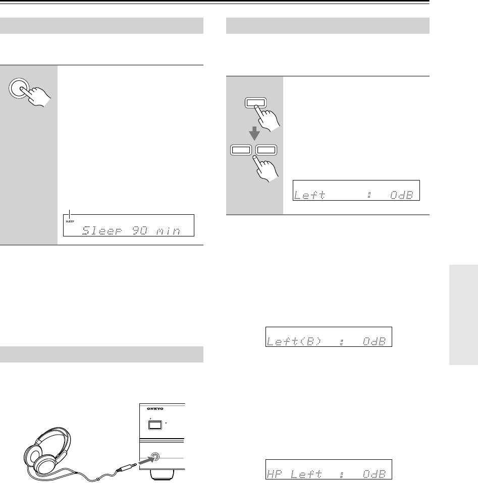
45
Common Functions
—Continued
With the sleep timer, you can set the AV receiver so that
it turns off automatically after a specified period.
To cancel the sleep timer,
press the [SLEEP] button
repeatedly until the SLEEP indicator disappears.
To check the remaining sleep time,
press the [SLEEP]
button. Note that if you press the [SLEEP] button while
the sleep time is being displayed, you’ll shorten the sleep
time by 10 minutes.
For private listening, you can connect a pair of stereo
headphones (1/4-inch phone plug) to the AV receiver’s
PHONES jack.
Notes:
•Always turn down the volume before connecting your
headphones.
• Speaker sets A and B are turned off while the head-
phones plug is inserted in the PHONES jack.
•When you connect a pair of headphones, the listening
mode is set to Stereo, unless it was set to Pure Audio,
Mono, Stereo, or Direct, in which case it stays the
same.
• When the multichannel DVD input is selected, only
the front left and front right channels can be heard in
the headphones.
You can adjust the volume of each speaker in speaker set
A. These temporary adjustments are cancelled when the
AV receiver is set to Standby.
Notes:
•You cannot use this function while the AV receiver is
muted.
• Speakers that are set to No or None in the Speaker
Configuration cannot be adjusted.
■
Speaker Set B
While speaker set B is on, you can adjust the volume of
the left and right speakers, from –12 dB to +12 dB.
• These settings are stored when the AV receiver is set
to Standby.
•While speaker set B is on, you cannot adjust the levels
of speaker set A’s surround back speakers.
■
Headphones
While a pair of headphones is connected, you can adjust
the volume of each headphone speaker, from –12 dB to
+12 dB each.
• These settings are stored when the AV receiver is set
to Standby.
Using the Sleep Timer
Press the remote controller’s
[SLEEP] button repeatedly to
select the required sleep time.
You can set the sleep time from 90 to 10
minutes in 10 minute steps.
The SLEEP indicator appears on the
display when the sleep timer has been
set, as shown. The specified sleep time
appears on the display for about 5 sec-
onds, then the previous display reap-
pears.
Using Headphones
SLEEP
SLEEP indicator
STANDBY
STANDBY/ON
PHONES
Adjusting Speaker Levels
1
Use the remote controller’s
[CH SEL] button to select each
speaker, and use the [LEVEL–]
and [LEVEL+] buttons to adjust
the volume.
You can adjust the volume of each
speaker from –12 dB to +12 dB
(–15 dB to +12 dB for the subwoofer).
CH SEL
LEVEL
+
LEVEL
-
HT-S790_En.book Page 45 Friday, February 17, 2006 3:28 PM
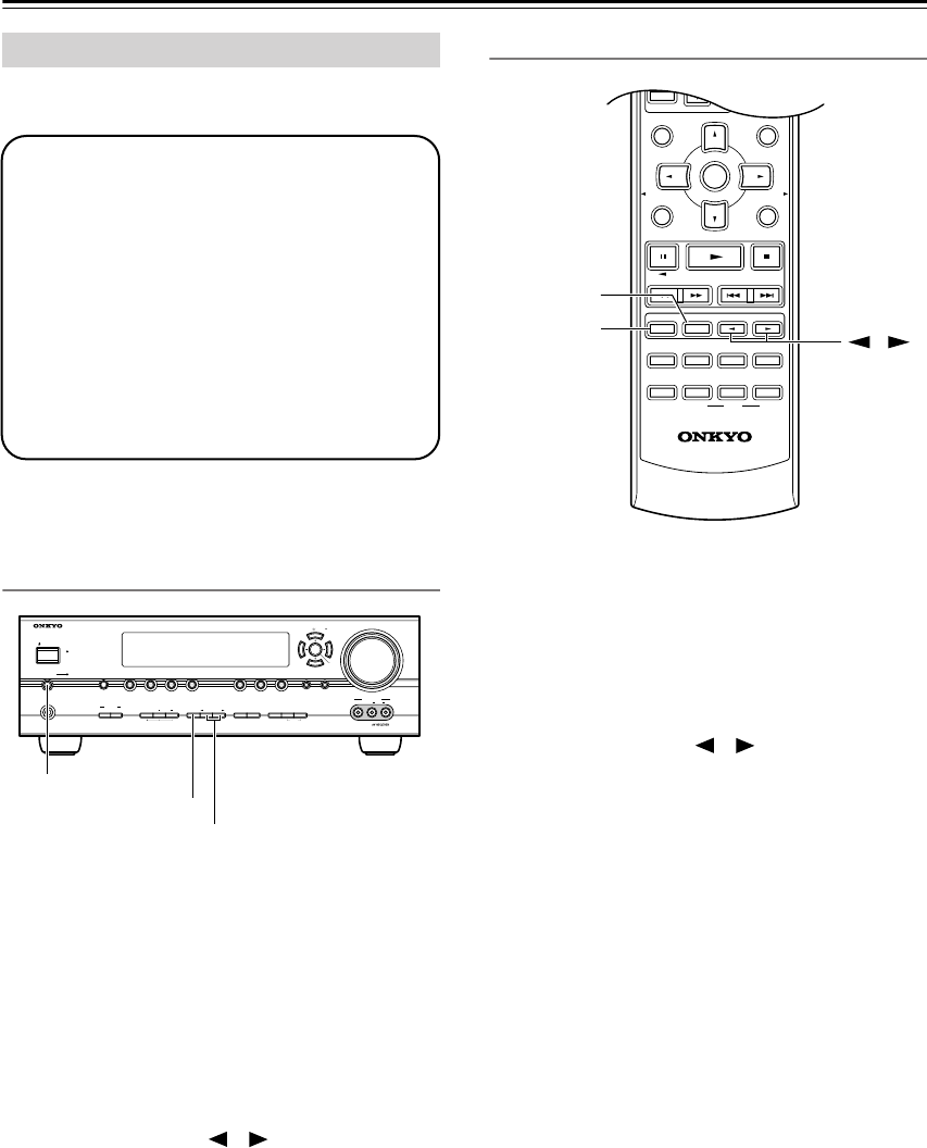
46
Using the Listening Modes
For a description of each listening mode, see “About the
Listening Modes” on page 48.
Selecting on the AV Receiver
■
[PURE AUDIO] button (not North American
model)
This button selects the Pure Audio listening mode.
When this mode is selected, the AV receiver outputs
no video signals and its display is turned off.
Pressing this button again will select the previous lis-
tening mode.
■
[STEREO] button
This button selects the Stereo listening mode.
■
LISTENING MODE [ ]/[ ] buttons
Pressing these buttons repeatedly cycles through all
of the listening modes that can be used with the cur-
rent input source.
Selecting with the Remote Controller
■
[STEREO] button
This button selects the Stereo listening mode.
■
[SURROUND] button
This button selects the Dolby Digital and DTS listen-
ing modes and the Neural Surround listening mode
(North American model only).
■
LISTENING MODE [ ]/[ ] buttons
Pressing these buttons repeatedly cycles through all
of the listening modes that can be used with the cur-
rent input source.
Selecting Listening Modes
• The Dolby Digital and DTS listening modes
can only be selected if your DVD player is
connected to the AV receiver with a digital
audio connection (coaxial or optical).
•Listening mode availability depends on the
format of the current input signal.
• While a pair of headphones is connected,
you can select only the Pure Audio (not
North American model), Mono, Direct, or
Stereo listening mode.
• The listening modes cannot be selected
while speaker set A is off.
MASTER VOLUME
VIDEO
STANDBY
TONE DISPLAYSTEREO RT/PTY/TP MEMORY
DIGITAL
INPUT
TUNING
MODEAB
SPEAKERS
TUNERTAPE
VIDEO 3VIDEO 2VIDEO 1
VCR
DVDMULTI CH C
DSETUPRETURN
CLEAR
LISTENING MODE
AUDIOLR
VIDEO 3 INPUT
STANDBY/ON
PHONES
PURE AUDIO
TUNING PRESET
ENTER
PURE AUDIO
STEREO
LISTENING MODE
MUTING
PREVIOUS
MENU
GUIDE
TOP MENU
SP A
/
B
SETUPRETURN
PLAYLIST/CAT PLAYLIST/CAT
RANDOM
SUBTITLE
PLAY MODE
AUDIO REPEAT
RC-649M
HDDDVDVCR
LISTENING MODE
TV
DISPLAY
TEST
TONE
CH SEL
OR-EQ
SURROUND
STEREO
CINE FLTR
LEVEL
+
LEVEL
-
L NIGHT
VOL
VOL
INPUT
ENTER
CH
DISC
ALBUM
,
STEREO
SURROUND
HT-S790_En.book Page 46 Friday, February 17, 2006 3:28 PM
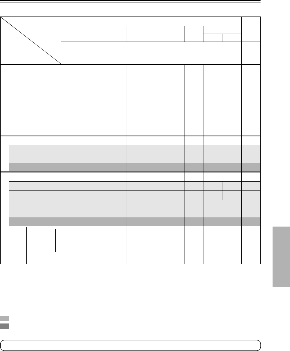
47
Using the Listening Modes
—Continued
The following table shows which listening modes can be used with each input signal format.
: Only available on 6.1/7.1-channel playback systems. Not available while speaker set B is on.
: Only available on 7.1-channel playback systems. Not available while speaker set B is on.
Source format
Listening mode
Analog,
PCM
*1
*1. In the Pure Audio and Direct listening modes, 32 kHz, 44.1 kHz, and 48 kHz PCM is processed at 64 kHz, 88.2 kHz, and 96 kHz respectively. In
listening modes other than Pure Audio, Direct, and Stereo, 64 kHz, 88.2 kHz, and 96 kHz PCM is processed at 32 kHz, 44.1 kHz, and 48 kHz
respectively.
Dolby Digital DTS/DTS 96/24
*2
*2. In listening modes other than Pure Audio, Direct, Stereo, and DTS 96/24, DTS 96/24 sources are processed as normal DTS.
Multich
analog
3/2.1
2/2.1 2/0 1/0, 1+1 Other 3/2.1
2/2.1 2/0 DTS-ES
Discrete Matrix
CD, TV,
radio,
cassette,
etc.
DVD, DTV, etc. DVD, CD, etc. DVD
Pure Audio (Not North
American models)
Direct
✔✔✔✔✔✔✔ ✔ ✔
Stereo
Mono
✔✔✔✔✔✔✔ ✔
Multich
✔
PLIIx Movie/Music/Game
*3
Neo:6 Cinema
Neo:6 Music
*3. If the Surr Back parameter is set to None, or speaker set B is on, normal Pro Logic II is used.
✔✔ ✔
Neural Surround (North
American models only)
✔
*4
*4. Not available for 88.2 kHz and 96 kHz PCM input signals.
Dolby
Dolby D
✔✔
Dolby D + Neo:6
Dolby D EX
Dolby D+PLIIx Music
✔
Dolby D+PLIIx Movie
✔
DTS
DTS, DTS 96/24
✔✔
*5
*5. If the Surr Back setting is set to None, or speaker set B is on, normal DTS is used.
DTS-ES Discrete
✔
DTS-ES Matrix
✔
DTS+Neo:6
DTS+Dolby EX
DTS+PLIIx Music
✔
DTS+PLIIx Movie
✔
Onkyo
Original
DSP
Mono Movie
Orchestra
Unplugged
*6
Studio-Mix
TV Logic
All Ch Stereo
Full Mono
*6. Available only when surround speakers are connected.
✔✔✔✔✔✔✔ ✔
Tip: To check the format of the digital input signal, see “Displaying Source Information” on page 37.
HT-S790_En.book Page 47 Friday, February 17, 2006 3:28 PM
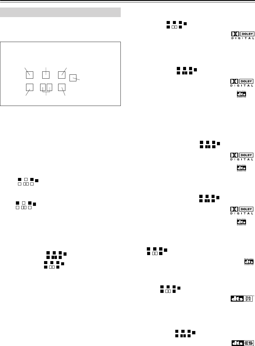
48
Using the Listening Modes
—Continued
The AV receiver’s listening modes can transform your
listening room into a movie theater or concert hall, with
high fidelity and stunning surround sound.
Pure Audio (not North American models)
In this mode, the display and video circuitry are turned
off, minimizing possible noise sources for the ultimate in
high-fidelity reproduction. (As the video circuitry is
turned off, no video signals are output in this mode.)
Direct
In this mode, audio from the input source is output
directly with minimal processing, providing high-fidel-
ity reproduction. All of the source’s audio channels are
output as they are.
Stereo
Sound is output by the front left and right speakers and
subwoofer.
Mono
Use this mode when watching an old movie with a mono
soundtrack, or use it with the foreign language
soundtracks recorded in the left and right channels of
some movies. It can also be used with DVDs or other
sources containing multiplexed audio, such as karaoke
DVDs.
Dolby Pro Logic IIx
Dolby Pro Logic II
Dolby Pro Logic IIx
expands any 2-channel source for
7.1-channel playback. It provides a very natural and
seamless surround-sound experience that fully envelops
the listener. As well as music and movies, video games
can also benefit from the dramatic spatial effects and
vivid imaging. If you’re not using any surround back
speakers,
Dolby Pro Logic II
will be used instead of
Dolby Pro Logic IIx.
• PLIIx Movie
Use this mode with any stereo or Dolby Surround
(Pro Logic) movie (e.g., TV, DVD, VHS).
• PLIIx Music
Use this mode with any stereo or Dolby Surround
(Pro Logic) music source (e.g., CD, radio, cassette,
TV, VHS, DVD).
• PLIIx Game
Use this mode with video games, especially those that
bear the Dolby Pro Logic II logo.
Dolby Digital
Use this mode with DVDs that bear the
Dolby Digital logo, and Dolby Digital TV
broadcasts. This is the most common digital surround-
sound format, and it’ll put you right in the middle of the
action, just like being in a movie theater or concert hall.
Dolby Digital EX
DTS+Dolby EX
These modes expand 5.1-channel Dolby
Digital and DTS sources for 6.1/7.1-chan-
nel playback. They’re especially suited to
Dolby Digital EX soundtracks that include
a matrix-encoded surround back channel. The additional
channel adds an extra dimension and provides an envel-
oping surround sound experience, perfect for rotating
and fly-by sound effects. Use them with DVDs that bear
the Dolby Digital or DTS logo.
Dolby Digital+PLIIx Music
DTS+PLIIx Music
These modes use the Pro Logic IIx Music
mode to expand 5.1-channel Dolby Digital
and DTS sources for 6.1/7.1-channel play-
back. Use them with Dolby Digital or
DTS 5.1 music sources (e.g., DVD and Dolby Digital TV
broadcasts).
Dolby Digital+PLIIx Movie
DTS+PLIIx Movie
These modes use the Pro Logic IIx Movie
mode to expand 5.1-channel Dolby Digital
and DTS sources for 7.1-channel play-
back. Use them with Dolby Digital and
DTS 5.1 movies (e.g., DVD and select digital TV broad-
casts).
DTS
The DTS digital surround-sound format supports
up to 5.1 discrete channels and uses less com-
pression for high-fidelity reproduction. Use it
with DVDs and CDs that bear the DTS logo.
DTS 96/24
This mode is for use with DTS 96/24
sources. This is high-resolution DTS with a
96 kHz sampling rate and 24-bit resolution, providing
superior fidelity. Use it with DVDs that bear the DTS
96/24 logo.
DTS-ES Discrete
This mode is for use with DTS-ES Discrete
soundtracks, which use a discrete surround
back channel for true 6.1/7.1-channel playback. The
seven totally separate audio channels provide better spa-
tial imaging and 360-degree sound localization, perfect
for sounds that pan across the surround channels. Use it
with DVDs that bear the DTS-ES logo, especially those
with a DTS-ES Discrete soundtrack.
About the Listening Modes
The illustration shows which speakers are active in
each listening mode with 7.1 channel speaker sys-
tem.
Front left Center Front right
Subwoofer
Surround rightSurround
back left/ right
Surround left
HT-S790_En.book Page 48 Friday, February 17, 2006 3:28 PM
49
Using the Listening Modes
—Continued
DTS-ES Matrix
This mode is for use with DTS-ES Matrix
soundtracks, which use a matrix-encoded
back-channel for 6.1/7.1-channel playback. Use it with
DVDs that bear the DTS-ES logo, especially those with
a DTS-ES Matrix soundtrack.
DTS Neo:6
This mode expands any 2-channel source for 6.1-chan-
nel playback. It uses six full-bandwidth channels of
matrix decoding for matrix-encoded material, providing
a very natural and seamless surround sound experience
that fully envelops the listener.
• Neo:6 Cinema
Use this mode with any stereo movie (e.g., TV, DVD,
VHS).
• Neo:6 Music
Use this mode with any stereo music source (e.g.,
CD, radio, cassette, TV, VHS, DVD).
Dolby Digital + Neo:6
DTS+Neo:6
This mode uses Neo:6 to expand 5.1-chan-
nel Dolby Digital and DTS sources for
6.1/7.1-channel playback. Use it with
DVDs that bear the Dolby Digital or DTS
logo and feature a 5.1-channel soundtrack.
Neural Surround
(North American models only)
Neural Surround represents the latest advancement in
surround technology developed for music and is adopted
by XM Satellite Radio for digital radio broadcast of sur-
round recordings and live events in surround sound.
Neural Surround employs psychoacoustic frequency-
domain processing, which allows delivery of a more
detailed sound stage, with superior channel separation
and localization of audio elements. System playback is
scalable from 5.1 to 7.1 multichannel surround playback.
Onkyo Original DSP Modes
Mono Movie
This mode is suitable for old movies and other mono
sources. The center speaker outputs the sound as it is,
while reverb is applied to the sound output by the other
speakers, giving presence to even mono material.
Orchestra
Suitable for classical or operatic music, this mode
emphasizes the surround channels in order to widen the
stereo image, and simulates the natural reverberation of
a large hall.
Unplugged
Suitable for acoustic instruments, vocals, and jazz, this
mode emphasizes the front stereo image, giving the
impression of being right in front of the stage.
Studio-Mix
Suitable for rock or pop music, listening to music in this
mode creates a lively sound field with a powerful acous-
tic image, like being at a club or rock concert.
TV Logic
This mode adds realistic acoustics to TV shows pro-
duced in a TV studio, surround effects to the entire
sound, and clarity to voices.
All Ch Stereo
Ideal for background music, this mode fills the entire lis-
tening area with stereo sound from the front, surround,
and surround back speakers.
Full Mono
In this mode, all speakers output the same sound in
mono, so the sound you hear is the same regardless of
where you are within the listening room.
HT-S790_En.book Page 49 Friday, February 17, 2006 3:28 PM
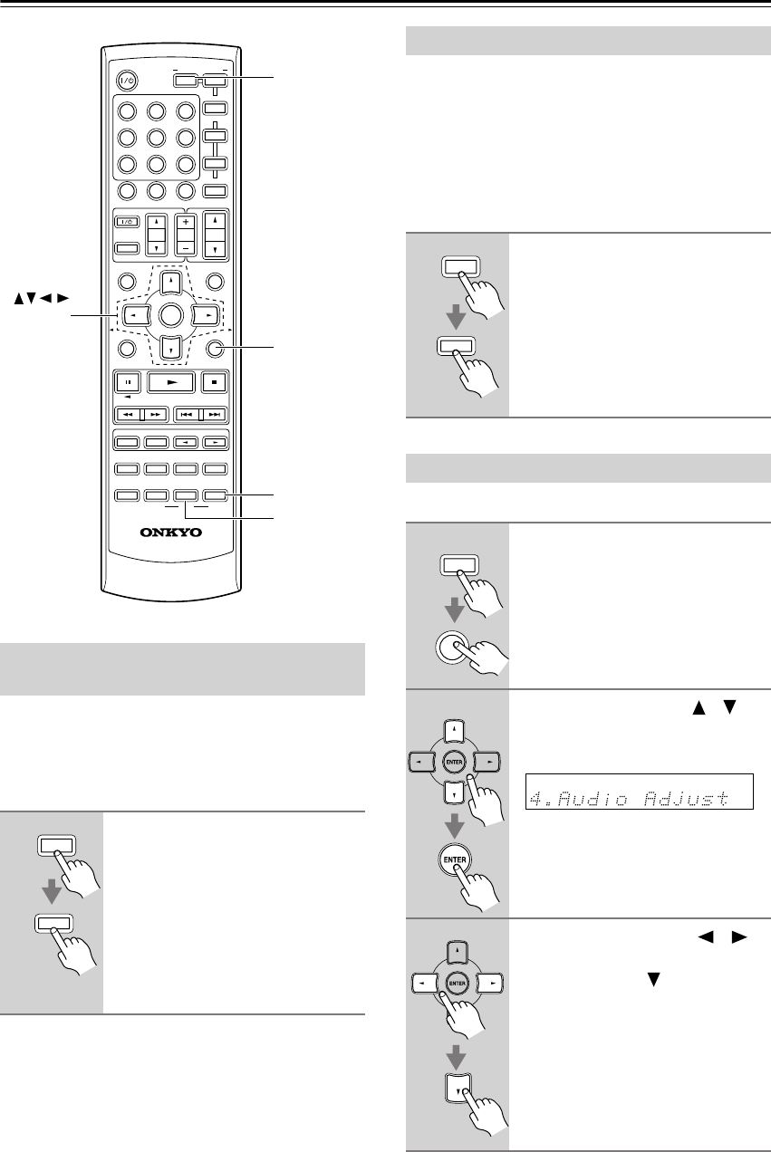
50
Using the Listening Modes
—Continued
With the Late Night function, you can reduce the
dynamic range of Dolby Digital material so that you can
still hear quiet parts even when listening at low volume
levels—ideal for watching movies late at night when you
don’t want to disturb anyone.
Notes:
• The effect of the Late Night function depends on the
Dolby Digital material that you are playing, and with
some material there will be little or no effect.
• The Late Night function is set to Off when the AV
receiver is set to Standby.
With the CinemaFILTER, you can soften overly bright
movie soundtracks, which are typically mixed for repro-
duction in a movie theater.
CinemaFILTER can be used with the following listening
modes: Dolby Digital, Dolby Digital EX, PLII/IIx
Movie, DTS, DTS-ES, DTS Neo:6 Cinema, DTS 96/24,
Dolby/DTS+PLIIx Movie, Dolby/DTS+Neo:6, and
DTS+Dolby EX.
The Audio Adjust settings only affect speaker set A.
Using the Late Night Function
(Dolby Digital only)
1
Press the [RECEIVER] REMOTE
MODE button, and then press the
[L NIGHT] button repeatedly to
select:
Off:
Late Night function off.
Low:
Small reduction in dynamic
range.
High:
Big reduction in dynamic
range.
MUTING
PREVIOUS
MENU
GUIDE
TOP MENU
SP A
/
B
SETUPRETURN
PLAYLIST/CAT PLAYLIST/CAT
RANDOM
SUBTITLE
PLAY MODE
AUDIO REPEAT
RC-649M
--
/
---
TAPE
M
D/CDR
HDD
CABLE
ON/STANDBY
DIMMER
ENT
D TUN
SLEEP
10 11 12
INPUT SELECTOR
HDDDVDVCR
REMOTE MODE
V
1
V
2
V
3
C
DTAPE TUNER
DVD
MULTI CH
LISTENING MODE
TV
DISPLAY
TEST
TONE
CH SEL
OR-EQ
SURROUND
STEREO
CINE FLTR
LEVEL
+
LEVEL
-
L NIGHT
VOL
VOL
SAT
VCR
TV
DVD
RECEIVER
C
D
INPUT
+10
0
CLR
123
456
789
ENTER
CH
DISC
ALBUM
SETUP
RECEIVER
L NIGHT
CINE FLTR
ENTER
RECEIVER
L NIGHT
Using the CinemaFILTER
1
Press the [RECEIVER] REMOTE
MODE button, and then press the
[CINE FLTR] button repeatedly to
select:
On:
CinemaFILTER on.
Off:
CinemaFILTER off.
Using the Audio Adjust Settings
1
Press the [RECEIVER] button fol-
lowed by the [SETUP] button.
2
Use the Up and Down [ ]/[ ]
buttons to select “4. Audio
Adjust,” and then press [ENTER].
3
Use the Left and Right [ ]/[ ]
buttons to change the setting.
Press the Down [ ] button to
select the next setting.
Repeat this step for the other settings.
RECEIVER
CINE FLTR
RECEIVER
SETUP
HT-S790_En.book Page 50 Friday, February 17, 2006 3:28 PM

51
Using the Listening Modes
—Continued
The Audio Adjust settings are explained below.
Input Channel Settings
■
Multiplex
This setting determines which channel is output from a
stereo multiplex source. Use it to select audio channels
or languages with multiplex sources, multilingual TV
broadcasts, and so on.
Main:
The main channel is output (default).
Sub:
The sub channel is output.
M/S:
Both the main and sub channels are output.
■
Mono (2ch)
This setting determines which channel is output when
the Mono listening mode is used with a stereo source.
L+R:
Both the left and right channels are output
(default).
L:
Only the left channel is output.
R:
Only the right channel is output.
PLII and PLIIx Music Mode Settings
These settings apply to only 2-channel (stereo) sources.
■
Panorama
With this setting, you can broaden the width of the front
stereo image when using the Pro Logic II Music or Pro
Logic IIx Music listening mode.
On:
Panorama function on.
Off:
Panorama function off (default).
■
Dimension
With this setting, you can move the sound field forward
or backward when using the Pro Logic II Music or Pro
Logic IIx Music listening mode. The default value is 3.
It can be adjusted from 0 to 6. Higher settings move the
sound field forward. Lower settings move it backward.
If the stereo image feels too wide, or there’s too much
surround sound, move the sound field forward to
improve the balance. Conversely, if the stereo image
feels like it’s in mono, or there’s not enough surround
sound, move it backward.
■
Center Width
With this setting, you can adjust the width of the sound
from the center speaker when using the Pro Logic II
Music or Pro Logic IIx Music listening mode. Normally,
the center channel sound is output by only the center
speaker. (If you’re not using a center speaker, the center
channel sound will be distributed to the front left and
right speakers to create a phantom center). This setting
adjusts the front left, right, and center mix, allowing you
to adjust the weight of the center channel sound. It can
be adjusted from 0 to 7 (default value is 3).
DTS Neo:6 Music Mode Setting
■
Center Image
The DTS Neo:6 Music listening mode creates 6-channel
surround sound from 2-channel (stereo) sources. With
this setting, you can specify by how much the front left
and right channel output is attenuated in order to create
the center channel. It can be adjusted from 0 to 5 (default
value is 2). This setting has no effect if no center speaker
is connected.
When set to 0, the front left and right channel output is
attenuated by half (–6 dB), giving the impression that the
sound is located centrally. This setting works well when
the listening position is considerably off center. When
set to 5, the front left and right channels are not attenu-
ated, maintaining the original stereo balance.
Dolby Digital EX Input Signal Setting
■
Dolby EX
This setting determines how Dolby Digital EX signals
are handled. This setting is unavailable if no surround
back speakers are connected or speaker set B is on.
Auto:
If the source signal contains a Dolby Digital
EX flag, the Dolby Digital EX listening mode
is used (default).
Manual:
You can select Pro Logic IIx Movie, Pro
Logic IIx Music, Dolby Digital, or Dolby
Digital EX.
Multichannel Subwoofer Setting
■
SW Sens
On some DVD players, the signal from the multichannel
subwoofer output is 15 dB higher than normal. You can
change the subwoofer sensitivity to match your DVD
player. Note that this setting only affects signals con-
nected to the SUBWOOFER input jack of the multichan-
nel DVD input.
You can select 0 dB (default), +5 dB, +10 dB, or +15 dB.
If you find that your subwoofer is too loud, try the
+10 dB or +15 dB setting.
4
Press the [SETUP] button.
Setup closes.
SETUP
HT-S790_En.book Page 51 Friday, February 17, 2006 3:28 PM
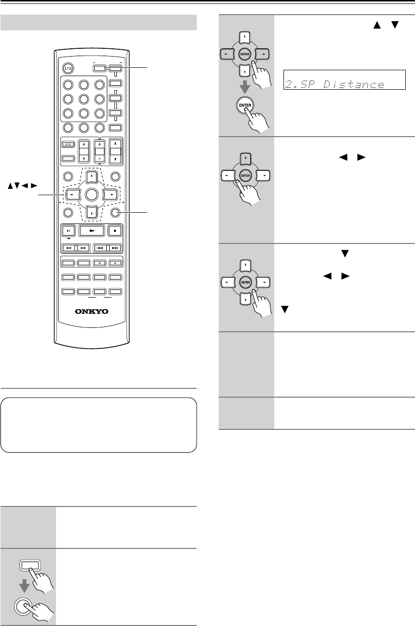
52
Advanced Setup
Speaker Distance
To get the best from surround sound, it’s important that
the sound from each speaker reaches the listener at the
same time. To achieve this, you need to specify the dis-
tance from each speaker to the listening position.
Notes:
• The Center and Subwoofer distances can be set up to
5 ft. (1.5 m) more or less than the Front distance. For
example, if the Front distance is set to 20 ft. (6 m), the
Center and Subwoofer distances can be set between 15
and 25 ft. (4.5 and 7.5 m).
•The Surround and Surround Back distances can be set
up to 5 ft. (1.5 m) more or 15 ft. (4.5 m) less than the
Front distance. For example, if the Front distance is set
to 20 ft. (6 m), the SurrRight, Surr Left, Surr Back R,
and Surr Back L distances can be set between 5 and 25
ft. (1.5 and 7.5 m).
Advanced Speaker Settings
1
Measure and make a note of the
distance from each speaker to
the listening position.
2
Press the [RECEIVER] button fol-
lowed by the [SETUP] button on
the remote controller.
MUTING
PREVIOUS
MENU
GUIDE
TOP MENU
SP A
/
B
SETUPRETURN
PLAYLIST/CAT PLAYLIST/CAT
RANDOM
SUBTITLE
PLAY MODE
AUDIO REPEAT
RC-649M
--
/
---
TAPE
M
D/CDR
HDD
CABLE
ON/STANDBY
DIMMER
ENT
D TUN
SLEEP
10 11 12
INPUT SELECTOR
HDDDVDVCR
REMOTE MODE
V1V2V3
C
DTAPE TUNER
DVD
MULTI CH
LISTENING MODE
TV
DISPLAY
TEST
TONE
CH SEL
OR-EQ
SURROUND
STEREO
CINE FLTR
LEVEL
+
LEVEL
-
L NIGHT
VOL
VOL
SAT
VCR
TV
DVD
RECEIVER
C
D
INPUT
+10
0
CLR
123
456
789
ENTER
CH
DISC
ALBUM
SETUP
RECEIVER
ENTER
The speaker distance setting cannot be
changed while a pair of headphones is con-
nected, speaker set B is on, or the multichan-
nel input is being used.
SETUP
RECEIVER
3
Use the Up and Down [ ]/[ ]
buttons to select “2. SP Dis-
tance,” and then press the
[ENTER] button.
4
While “Unit” is displayed, use the
Left and Right [ ]/[ ] buttons to
select “feet” or “meters”.
feet:
Distances in feet. Can be set
from 1 to 30 feet in 1-foot
steps.
meters:
Distances in meters. Can be
set from 0.3 to 9 meters in
0.3-meter steps.
5
Use the Down [ ] button to
select “Front,” and use the Left
and Right [ ]/[ ] buttons to
specify the distance for the “front
speakers,” then press the Down
[] button to select the next
speaker.
6
Repeat step 5 for all speakers.
Note:
Speakers that you set to No or None in
the Speaker Configuration (page 54)
cannot be selected.
7
Press the [SETUP] button.
Setup closes.
HT-S790_En.book Page 52 Friday, February 17, 2006 3:28 PM
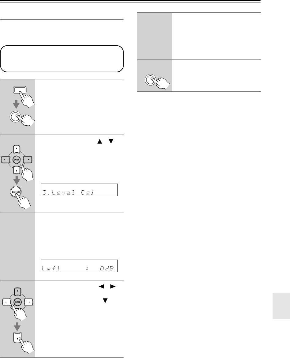
53
Advanced Setup
—Continued
Speaker Levels
With this function, you can adjust the volume of each
speaker so that all speakers can be heard equally at the
listening position.
Note:
•A quicker way to adjust the speaker levels is to press
the remote controller’s [TEST TONE] button to output
the test tone, use the [LEVEL–] and [LEVEL+] but-
tons to adjust the levels, and use the [CH SEL] button
to select the speakers.
1
Press the [RECEIVER] button fol-
lowed by the [SETUP] button on
the remote controller.
2
Use the Up and Down [ ]/[ ]
buttons to select “3. Level Cal,”
and then press the [ENTER] but-
ton.
A pink noise test tone is output by the
front left speaker.
3
Turn up the volume so that you
can hear the test tone suffi-
ciently.
While each speaker outputs the test
tone, its name appears on the display, as
shown.
4
Use the Left and Right [ ]/[ ]
buttons to adjust the speaker
level, and use the Down [ ] but-
ton to select the next speaker.
The level can be adjusted from –12 to
+12 dB in 1 dB steps (–15 to +12 dB
for the subwoofer).
The speaker levels cannot be adjusted while a
pair of headphones is connected, speaker set
B is on, or the AV receiver is muted.
SETUP
RECEIVER
5
Repeat step 4 so that the level of
the test tone from each speaker
is the same.
Speakers that you set to No or None in
the Speaker Configuration (page 54) do
not output the test tone.
6
Press the [SETUP] button.
Setup closes.
Don’t forget to turn down the volume if
you turned it up while setting the levels.
SETUP
HT-S790_En.book Page 53 Friday, February 17, 2006 3:28 PM
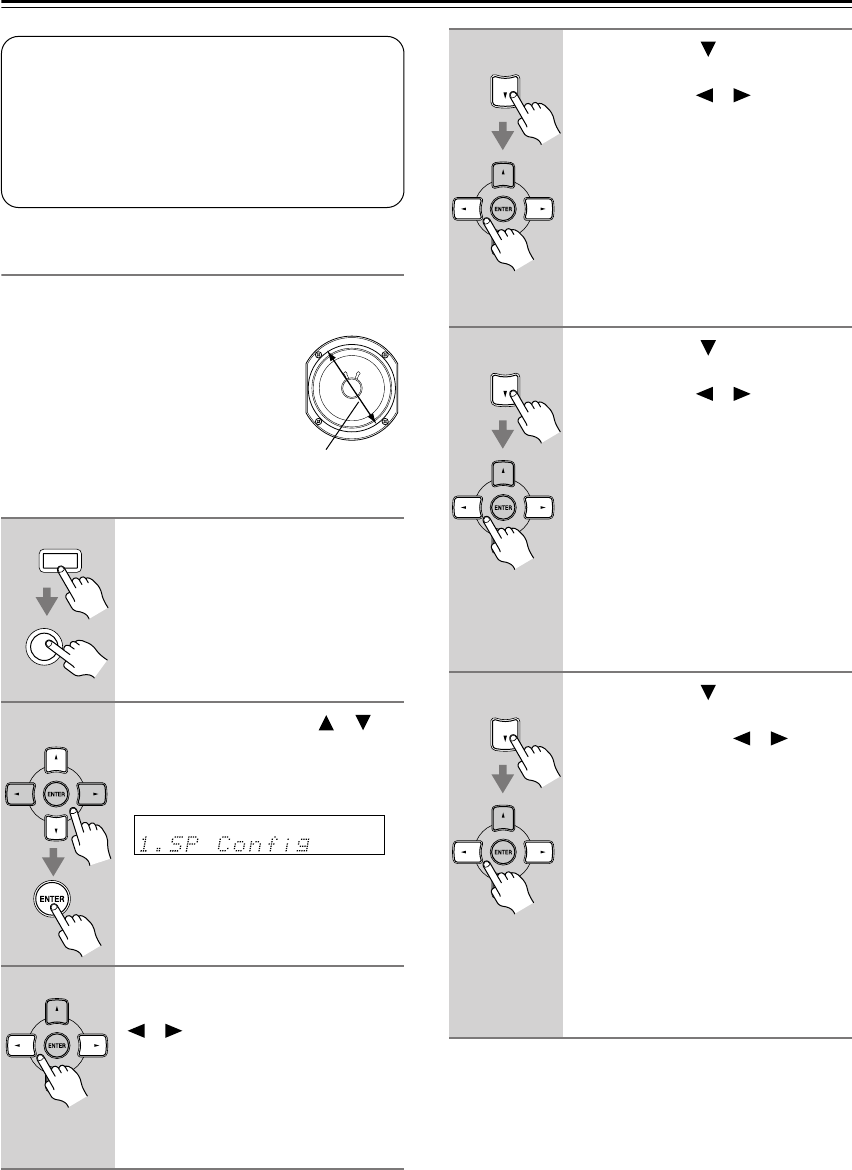
54
Advanced Setup
—Continued
Speaker Configuration
This section explains how to specify which speakers are
connected and their sizes.
For speakers with a cone diameter
larger than 6-1/2 inches (16 cm),
specify
Large
(full band)
.
For those
with a smaller diameter, specify
Small
(default crossover 100 Hz)
.
The crossover frequency can be
changed on page 55.
1
Press the [RECEIVER] button fol-
lowed by the [SETUP] button.
2
Use the Up and Down [ ]/[ ]
buttons to select “1. SP Config,”
and then press the [ENTER] but-
ton.
3
While the Subwoofer setting is
selected, use the Left and Right
[]/[ ] buttons to select
Yes
or
No
.
Yes:
Select if a subwoofer is con-
nected.
No:
Select if no subwoofer is con-
nected.
Speaker Configuration, Crossover Frequency,
and Double Bass settings only need to be
changed if you’re not using the speakers in
this package.
These settings cannot be changed while head-
phones are connected, speaker set B is on, or
the multichannel DVD input is being used.
Cone diameter
RECEIVER
SETUP
4
Use the Down [ ] button to
select “Front,” and then use the
Left and Right [ ]/[ ] buttons to
select
Small
or
Large
.
Small:
Select if the front speakers are
small.
Large:
Select if the front speakers are
large.
Note:
• If the Subwoofer setting in step 3 is
set to No, this setting is fixed at Large
and does not appear.
5
Use the Down [ ] button to
select “Center,” and then use the
Left and Right [ ]/[ ] buttons to
select
Small
,
Large
, or
None
.
Small:
Select if the center speaker is
small.
Large:
Select if the center speaker is
large.
None:
Select if no center speaker is
connected.
Note:
• If the Front setting in step 4 is set to
Small, the Large option cannot be
selected.
6
Use the Down [ ] button to
select “Surround,” and then use
the Left and Right [ ]/[ ] but-
tons to select
Small
,
Large
, or
None
.
Small:
Select if the surround speak-
ers are small.
Large:
Select if the surround speak-
ers are large.
None:
Select if no surround speakers
are connected.
Note:
• If the Front setting in step 4 is set to
Small, the Large option cannot be
selected.
HT-S790_En.book Page 54 Friday, February 17, 2006 3:28 PM
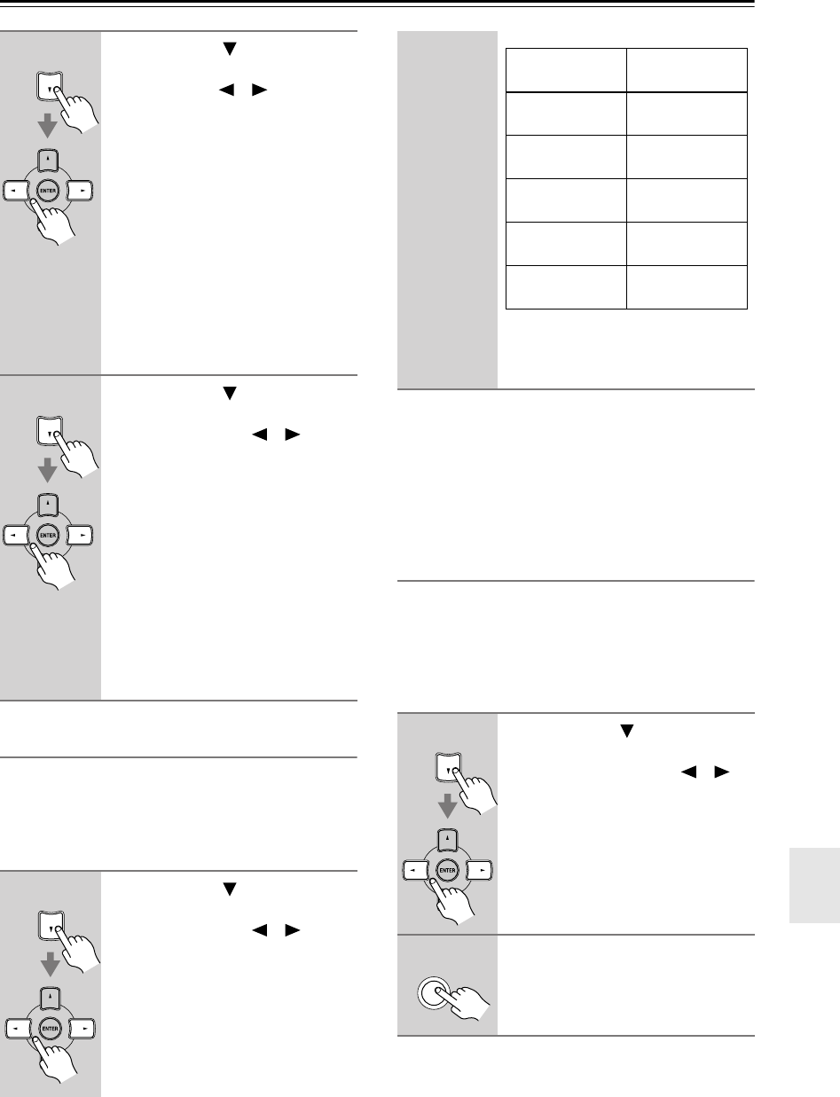
55
Advanced Setup
—Continued
Crossover Frequency
This setting only applies to the speakers that you speci-
fied as
Small
in the “Speaker Configuration” on page 54.
To get the best bass performance from your speaker sys-
tem, you need to set the crossover frequency according
to the size and frequency response of your speakers
Notes:
•For a more accurate setting, look up the frequency
response in the manuals supplied with your speakers
and set accordingly.
•Choose a higher crossover frequency if you want more
sound from your subwoofer.
Double Bass
With the Double Bass function, you can boost bass out-
put by feeding bass sounds from the front left and right
channels to the subwoofer. This function can be set only
if the Subwoofer setting (step 3) is set to Yes, and the
Front setting (step 4) is set to Large in the Speaker Con-
figuration on page 54.
7
Use the Down [ ] button to
select “Surr Back,” and use the
Left and Right [ ]/[ ] buttons to
select
Small
,
Large
, or
None
.
Small:
Select if the surround back
speakers are small.
Large:
Select if the surround back
speakers are large.
None:
Select if no surround back
speakers are connected.
Notes:
•If the Surround setting in step 6 is set
to None, this setting does not appear.
•If the Surround setting in step 6 is set
to Small, the Large option cannot be
selected.
8
Use the Down [ ] button to
select “Surr Back Ch,” and use
the Left and Right [ ]/[ ] but-
tons to select
2ch
or
1ch
.
2ch:
Select if two (left and right)
surround back speakers are
connected.
1ch:
Select if one surround back
speaker is connected.
Note:
• If the Surround and Surr Back set-
tings in steps 6 and 7 are set to None,
this setting does not appear.
Continue with step 9 of the “Crossover
Frequency” setting.
9
Use the Down [ ] button to
select “Crossover,” and then use
the Left and Right [ ]/[ ] but-
tons to select a crossover fre-
quency.
Use the diameter of the smallest
speaker in your system when choosing
the crossover frequency.
*Choose the setting suitable for the speaker.
Continue with step 10 of the “Double
Bass” setting below.
10
Use the Down [ ] button to
select “Double Bass,” and then
use the Left and Right [ ]/[ ]
buttons to select:
On:
Double Bass function on.
Bass from the front left and
right channels is also fed to
the subwoofer (default).
Off:
Double Bass function off.
11
Press the [SETUP] button.
Setup closes.
Speaker cone
diameter
Crossover
frequency
Over 8 in.
(20 cm) 40/50/60Hz*
6-1/2 to 8 in.
(16–20 cm) 80Hz
5-1/4 to 6-1/2 in.
(13–16 cm) 100Hz (default)
3-1/2 to 5-1/4 in.
(9–13 cm) 120Hz
Under 3-1/2 in.
(9 cm) 150/200Hz*
SETUP
HT-S790_En.book Page 55 Friday, February 17, 2006 3:28 PM
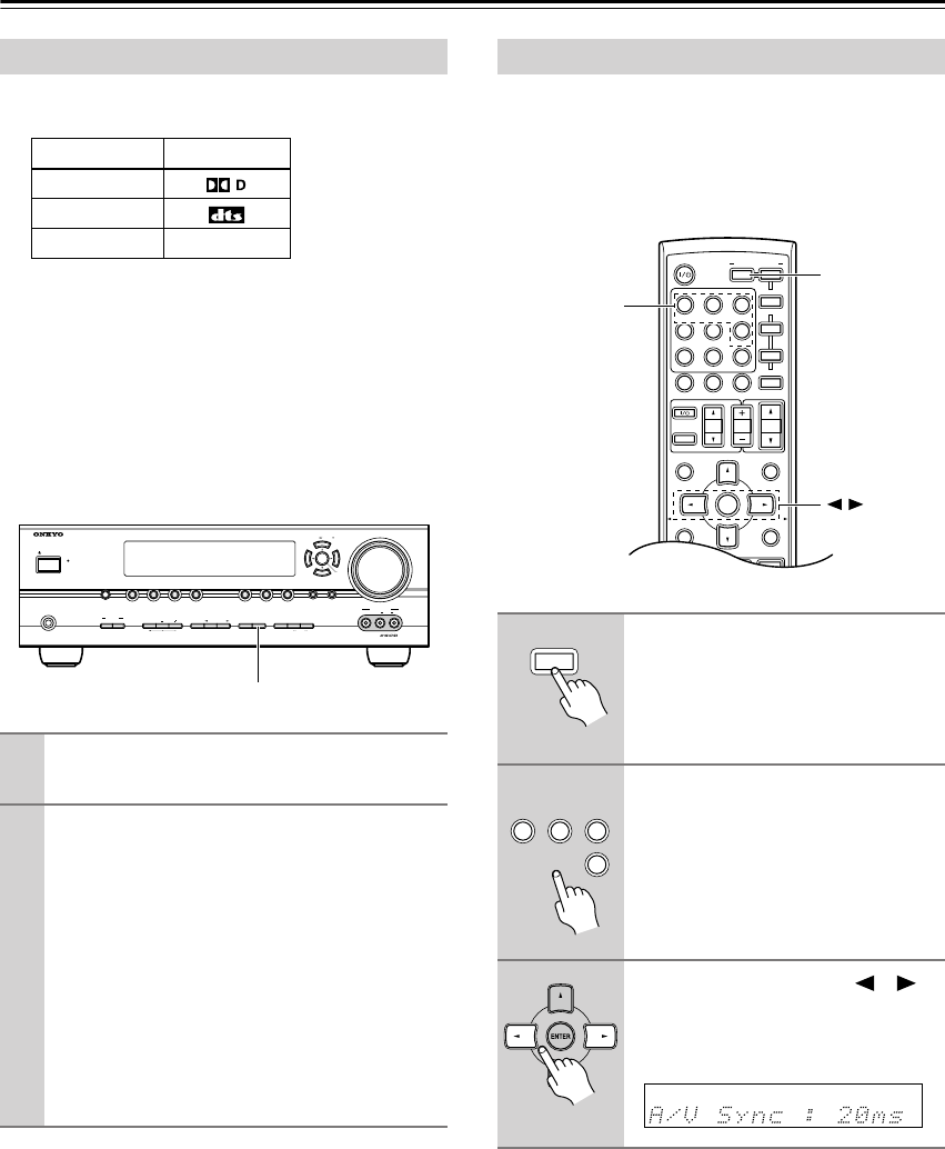
56
Advanced Setup
—Continued
The following table shows the display indicator for each
digital signal format.
Normally, the AV receiver detects the signal format auto-
matically. However, if you experience either of the fol-
lowing issues when playing PCM or DTS material, you
can specify the signal format as either PCM or DTS:
•If the beginnings of tracks from a PCM source are cut
off, try the PCM setting.
•If noise is produced when fast forwarding or reversing
a DTS CD, try the DTS setting.
When using progressive scanning on your DVD player,
you may find that the picture and sound are out of sync.
With this setting, you can correct this by delaying the
audio signals. You can set it from 0 to 100 milliseconds
(ms) in 20 millisecond steps.
Note:
• This setting is not available when the Pure Audio lis-
tening mode is used, or the Direct listening mode is
used with an analog input signal.
Digital Input Signal Formats
Format Display
Dolby Digital
DTS
PCM
1
Press and hold the AV receiver’s [DIGITAL
INPUT] button for about 3 seconds.
2
While “Auto” is displayed (about 3 sec-
onds), press the [DIGITAL INPUT] button
repeatedly to select: PCM, DTS, or Auto.
PCM:
Only PCM format input signals will be
heard. If the input signal is not PCM, the PCM
indicator will flash and there will be no sound.
DTS:
Only DTS format input signals will be
heard. If the input signal is not DTS, the DTS
indicator will flash and there will be no sound.
Auto (default):
The format is detected automati-
cally. If no digital input signal is present, the
corresponding analog input is used instead.
PCM
MASTER VOLUME
VIDEO
STANDBY
TONE DISPLAYSTEREO DIMMER MEMORY
DIGITAL
INPUT
TUNING
MODEAB
SPEAKERS
TUNERTAPE
VIDEO 3VIDEO 2VIDEO 1
VCR
DVDMULTI CH C
DSETUPRETURN
CLEAR
LISTENING MODE
AUDIOLR
VIDEO 3 INPUT
STANDBY/ON
PHONES
TUNING PRESET
ENTER
DIGITAL INPUT
Correcting Sound and Picture Sync
1
Press the [RECEIVER] REMOTE
MODE button.
2
Press and hold, for more than 4
seconds, the input selector but-
ton for the input source that you
want to correct.
This can be the [DVD], [VIDEO 1],
[VIDEO 2], or [VIDEO 3] input
source.
3
Use the Left and Right [ ]/[ ]
buttons to adjust the delay from 0
to 100 milliseconds in 20 milli-
second steps.
MUTING
PREVIOUS
MENU
GUIDE
TOP MENU
SP A
/
B
SETUPRETURN
PLAYLIST/CAT PLAYLIST/CAT
--
/
---
TAPE
M
D/CDR
HDD
CABLE
ON/STANDBY
DIMMER
ENT
D TUN
SLEEP
10 11 12
INPUT SELECTOR
REMOTE MODE
V
1
V
2
V
3
C
DTAPE TUNER
DVD
MULTI CH
TV VOL
VOL
SAT
VCR
TV
DVD
RECEIVER
C
D
INPUT
+10
0
CLR
123
456
789
ENTER
CH
DISC
ALBUM
RECEIVER
INPUT
SELECTOR
RECEIVER
V1V2V3
DVD
123
6
HT-S790_En.book Page 56 Friday, February 17, 2006 3:28 PM
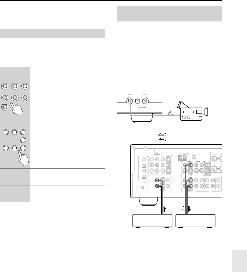
57
Recording
This section explains how to record the selected input
source to a component with recording capability, and
how to record audio and video from different sources.
You can only record to a component that’s connected to
the TAPE OUT or VIDEO 1 OUT jacks.
See pages 22–33 for information on connecting your AV
components.
Notes:
•You cannot record from a component that’s connected
to a digital input. Only analog inputs can be recorded.
• The surround sound effects provided by the listening
modes cannot be recorded.
•You cannot record from a component that’s connected
to the multichannel DVD input.
•If you select another input source while recording, that
input source will be recorded instead.
• While the Pure Audio listening mode is selected, the
VIDEO 1 OUT V and S jacks don’t output video sig-
nals, so select another mode when recording.
You can overdub audio onto your video recordings by
simultaneously recording audio and video from two sep-
arate sources. This is possible because only the audio
source is switched when an audio-only input source,
such as TAPE, TUNER, or CD, is selected, the video
source remains the same.
In the following example, audio from the CD player con-
nected to the CD IN jacks, and video from the camcorder
connected to the VIDEO 3 INPUT VIDEO jack are
recorded by the VCR connected to the VIDEO 1 OUT
jacks.
1.
Prepare the camcorder and CD player
for playback.
2.
Prepare the VCR for recording.
3.
Press the [VIDEO 3] input selector but-
ton.
4.
Press the [CD] input selector button.
This selects the CD player as the audio source, but
leaves the camcorder as the video source.
5.
Start recording on the VCR, then start
playback on the camcorder and CD
player.
Video from the camcorder and audio from the CD
player are recorded by the VCR.
Recording the Input Source
1
Use the input selector buttons to
select the component that you
want to record.
Audio signals from the selected input
source are output by the TAPE OUT
and VIDEO 1 OUT jacks.
You can listen to the source while
recording. The AV receiver’s VOL-
UME control has no effect on record-
ing.
2
On your recorder, start record-
ing.
3
Start playback on the source
component.
TAPE TUNER
C
D
VIDEO 3
DVD VIDEO 1
VCR
VIDEO 2
V1V2V3
C
DTAPE TUNER
DVD
123
6
789
Remote
controller
Recording Audio and Video from
Separate Sources
VIDEO AUDIOLR
VIDEO 3 INPUT
COA
XIAL
REMOTE
CONTROL
OPTICAL
1
Y
PB
PR
2
3
DIGITAL IN
L
R
L
R
L
L
R
R
V
S
CD TAPE
XM ANTENNA
FM
AM 75
COMPONENT
VIDEO 2 IN
IN IN
OUT
OUT
IN IN
OUT
IN IN IN
OUT
VIDEO 1 IN DVD IN
VIDEO
VIDEO 2 VIDEO 1
VIDEO 2 VIDEO 1 DVD
DVD
MONITOR
OUT
SURROUND BA
C
SPEAKERS
SUB
WOOFER
FRONT
SURROUND
SURR BACK
CENTER
Camcorder
VCRCD player
video signal
audio signal
HT-S790_En.book Page 57 Friday, February 17, 2006 3:28 PM
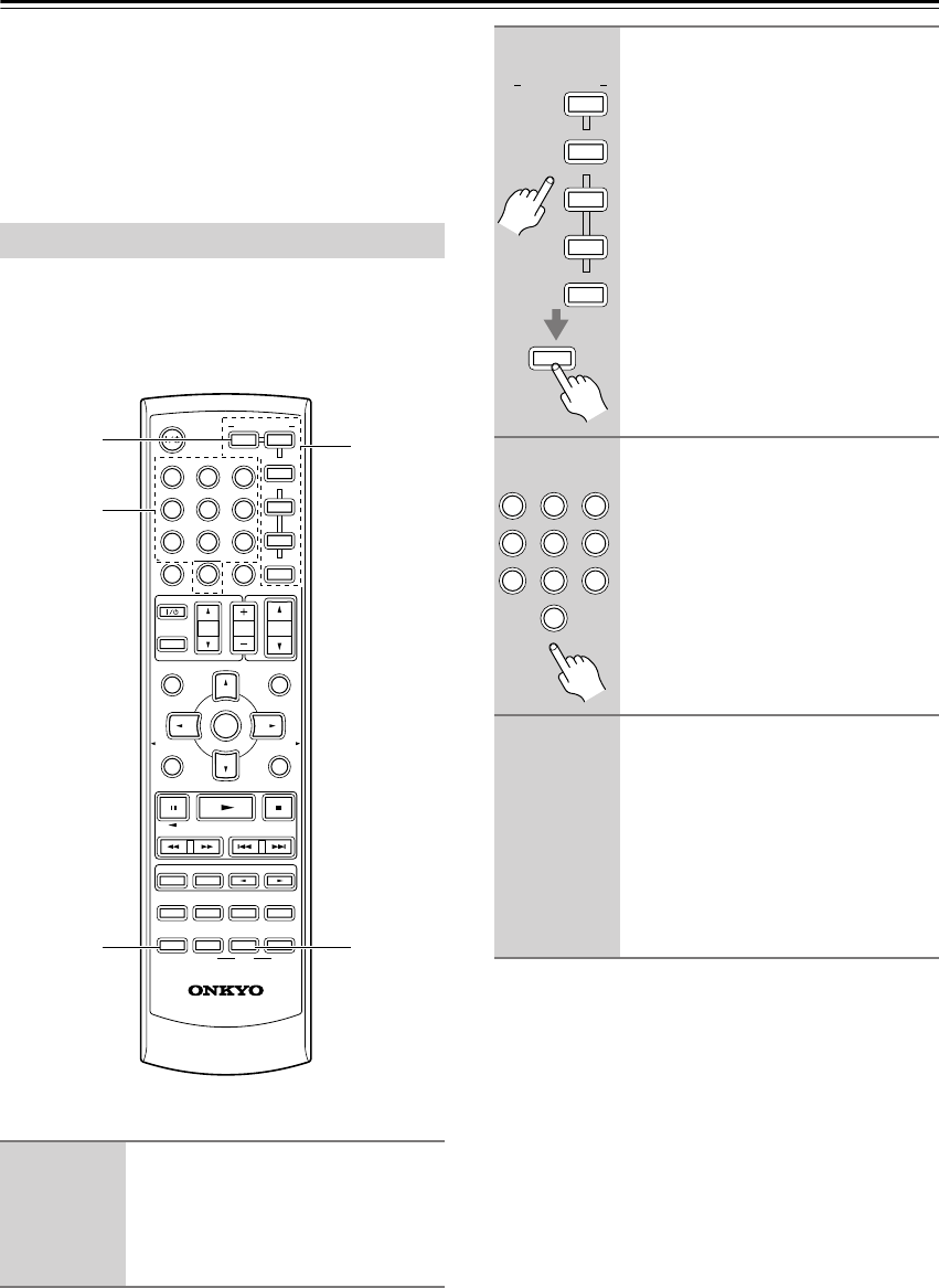
58
Controlling Other Components
You can use the AV receiver’s remote controller
(RC-649M) to control your other AV components,
including those made by other manufacturers. This sec-
tion explains how to enter the necessary remote control
code for the component that you want to control (e.g.,
DVD player, TV, or VCR).
To control another component, you must first enter the
appropriate remote control code to a REMOTE MODE
button. You’ll need to enter a code for each component
that you want to control.
Notes:
•A remote control code cannot be entered for the
[RECEIVER] REMOTE MODE button.
• The remote control codes provided are correct at the
time of printing, but are subject to change.
Entering Remote Control Codes
1
Look up the appropriate remote
control code in the separate
Remote Control Codes list.
The codes are organized by category
(e.g., DVD player, TV, etc.).
MUTING
PREVIOUS
MENU
GUIDE
TOP MENU
SP A
/
B
SETUPRETURN
PLAYLIST/CAT PLAYLIST/CAT
RANDOM
SUBTITLE
PLAY MODE
AUDIO REPEAT
RC-649M
--
/
---
TAPE
M
D/CDR
HDD
CABLE
ON/STANDBY
DIMMER
ENT
D TUN
SLEEP
10 11 12
INPUT SELECTOR
HDDDVDVCR
REMOTE MODE
V
1
V
2
V
3
C
DTAPE TUNER
DVD
MULTI CH
LISTENING MODE
TV
DISPLAY
TEST
TONE
CH SEL
OR-EQ
SURROUND
STEREO
CINE FLTR
LEVEL
+
LEVEL
-
L NIGHT
VOL
VOL
SAT
VCR
TV
DVD
RECEIVER
C
D
INPUT
+10
0
CLR
123
456
789
ENTER
CH
DISC
ALBUM
REMOTE
MODE
L NIGHT
DISPLAY
RECEIVER
Number
buttons
2
While holding down the REMOTE
MODE button that you want to
set, press the [DISPLAY] button
for 3 seconds.
The REMOTE MODE button lights up.
3
Within 30 seconds, use the num-
ber buttons to enter the 4-digit
remote control code.
The REMOTE MODE button flashes
twice.
4
Press the REMOTE MODE button
again to select the remote con-
troller mode, point the remote
controller at the component, and
check the operation.
If the remote controller doesn’t work as
expected, and several remote codes are
listed, try each one in turn and use the
one that works best.
M
D/CDR
HDD
CABLE
REMOTE MODE
SAT
VCR
TV
DVD
C
D
DISPLAY
DIMMER
ENT
11
V1V2V3
C
DTAPE TUNER
DVD
MULTI CH
0
123
456
789
HT-S790_En.book Page 58 Friday, February 17, 2006 3:28 PM
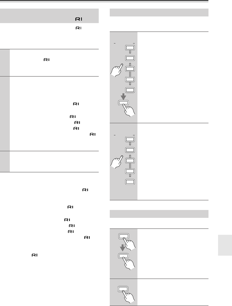
59
Controlling Other Components
—Continued
Onkyo components that are connected via are con-
trolled by pointing the remote controller at the AV
receiver, not the component. This allows you to control
components that are out of view, in a rack, for example.
If you want to control an Onkyo component by pointing
the remote controller directly at it, or you want to control
an Onkyo component that’s not connected via , use
the following remote control codes:
[DVD] REMOTE MODE button
0627:
Onkyo DVD player without (default)
[CD/MD/CDR/HDD] REMOTE MODE button
1817:
Onkyo CD player without (default)
0868:
Onkyo MD recorder without
1323:
Onkyo CD recorder without
1990:
HDD-compatible component without
Note:
If you connect an -capable Onkyo MD recorder, CD
recorder, or HDD-compatible component to the TAPE
IN/OUT or VIDEO 2 jacks, for remote operation to work
properly, you must set the Input Display to MD, CDR, or
HDD (see page 35).
You can reset a REMOTE MODE button to its default
remote control code.
You can reset the remote controller to its default settings.
Remote Control Codes for Onkyo
Components Connected via
1
Make sure the Onkyo component is con-
nected with an cable and an analog
audio cable (RCA).
See page 33 for details.
2
Enter the appropriate remote control code
for the [DVD] or [CD] REMOTE MODE but-
ton.
[DVD] REMOTE MODE button
1612:
Onkyo DVD player with
[CD/MD/CDR/HDD] REMOTE MODE button
1327:
Onkyo CD player with
1808:
Onkyo MD recorder with
1322:
Onkyo CD recorder with
1993:
HDD-compatible component with
See the previous page for how to enter remote
control codes.
3
Press the [DVD] or [CD] REMOTE MODE
button, point the remote controller at the
AV receiver, and operate the component.
Resetting REMOTE MODE Buttons
1
While holding down the REMOTE
MODE button that you want to
reset, press the [L NIGHT] button
for 3 seconds.
The REMOTE MODE button lights up.
2
Press the REMOTE MODE button
again.
The REMOTE MODE button flashes
twice, indicating that it’s been reset.
The [DVD] and [CD] REMOTE
MODE buttons are preprogrammed
with remote control codes for control-
ling Onkyo DVD players and CD play-
ers respectively. When these buttons
are reset, the preprogrammed code is
restored.
Resetting the Remote Controller
1
While holding down the
[RECEIVER] REMOTE MODE but-
ton, press the [L NIGHT] button
for 3 seconds.
The [RECEIVER] button lights up.
2
Press the [RECEIVER] REMOTE
MODE button again.
The [RECEIVER] button flashes twice,
indicating that it’s been reset.
M
D/CDR
HDD
CABLE
REMOTE MODE
SAT
VCR
TV
DVD
C
D
L NIGHT
M
D/CDR
HDD
CABLE
REMOTE MODE
SAT
VCR
TV
DVD
C
D
RECEIVER
L NIGHT
RECEIVER
HT-S790_En.book Page 59 Friday, February 17, 2006 3:28 PM
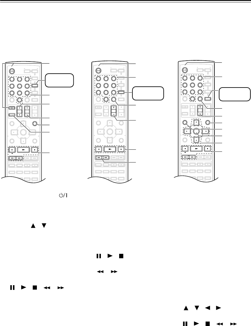
60
Controlling Other Components
—Continued
To control another component, point the remote controller at it and use the buttons explained below. (You must
select the appropriate remote control mode first.) With some AV components, certain buttons may not work as
expected, and some may not work at all.
■
Controlling a TV
A
[ON/STANDBY], TV [ ]*
Sets the TV to On or Standby.
B
Number buttons
Enter numbers.
C
TV VOL [ ]/[ ]*
Adjusts the TV’s volume.
D
[CH +/–]
Selects channels on the TV.
E
[PREVIOUS]
Selects the previous channel.
F
[TV INPUT]*
Selects the TV’s VCR input.
G
[], [ ], [ ], [ ], [ ]
Operates the VCR.
* Buttons marked with an asterisk
(*) are exclusively for control-
ling a TV and can be used at any-
time regardless of the current
remote controller mode.
■
Controlling a VCR
A
[ON/STANDBY]
Sets the VCR to On or Standby.
B
Number buttons
Select channels.
C
[CLR]
Cancels functions.
D
[CH +/–]
Selects channels on the VCR.
E
[], [ ], [ ]
Pause, Play, Stop.
F
[], []
Rewind and Fast forward.
■
Controlling a Satellite or
Cable Receiver
A
[ON/STANDBY]
Sets the satellite/cable receiver
to On or Standby.
B
Number buttons
Enter numbers.
C
[CLR]
Cancels functions.
D
[CH +/–]
Selects satellite/cable channels.
E
[PREVIOUS]
Selects the previous channel.
F
[GUIDE]
Displays the program guide.
G
[ENTER]
Confirms the selection.
H
[ ]/[ ]/[ ]/[ ]
Selects menu items.
I
[], [ ], [ ], [ ], [ ]
Operates the VCR.
MUTING
PREVIOUS
MENU
GUIDE
TOP MENU
SP A
/
B
SETUPRETURN
PLAYLIST/CAT PLAYLIST/CAT
RANDOM
SUBTITLE
PLAY MODE
AUDIO REPEAT
--
/
---
TAPE
M
D/CDR
HDD
CABLE
ON/STANDBY
DIMMER
ENT
D TUN
SLEEP
10 11 12
INPUT SELECTOR
HDDDVDVCR
REMOTE MODE
V
1
V
2
V
3
C
DTAPE TUNER
DVD
MULTI CH
LISTENING MODE
TV
DISPLAY
TEST
TONE
CH SEL
OR-EQ
SURROUND
STEREO
CINE FLTR
LEVEL
+
LEVEL
-
L NIGHT
VOL
VOL
SAT
VCR
TV
DVD
RECEIVER
C
D
INPUT
+10
0
CLR
123
456
789
ENTER
CH
DISC
ALBUM
A
2
3
4
6
5
7
Press [TV]
first
MUTING
PREVIOUS
MENU
GUIDE
TOP MENU
SP A
/
B
SETUPRETURN
PLAYLIST/CAT PLAYLIST/CAT
RANDOM
SUBTITLE
PLAY MODE
AUDIO REPEAT
--
/
---
TAPE
M
D/CDR
HDD
CABLE
ON/STANDBY
DIMMER
ENT
D TUN
SLEEP
10 11 12
INPUT SELECTOR
HDDDVDVCR
REMOTE MODE
V
1
V
2
V
3
C
DTAPE TUNER
DVD
MULTI CH
LISTENING MODE
TV
DISPLAY
TEST
TONE
CH SEL
OR-EQ
SURROUND
STEREO
CINE FLTR
LEVEL
+
LEVEL
-
L NIGHT
VOL
VOL
SAT
VCR
TV
DVD
RECEIVER
C
D
INPUT
+10
0
CLR
123
456
789
ENTER
CH
DISC
ALBUM
A
2
4
6
5
3
Press [VCR]
first
MUTING
PREVIOUS
MENU
GUIDE
TOP MENU
SP A
/
B
SETUPRETURN
PLAYLIST/CAT PLAYLIST/CAT
RANDOM
SUBTITLE
PLAY MODE
AUDIO REPEAT
--
/
---
TAPE
M
D/CDR
HDD
CABLE
ON/STANDBY
DIMMER
ENT
D TUN
SLEEP
10 11 12
INPUT SELECTOR
HDDDVDVCR
REMOTE MODE
V
1
V
2
V
3
C
DTAPE TUNER
DVD
MULTI CH
LISTENING MODE
TV
DISPLAY
TEST
TONE
CH SEL
OR-EQ
SURROUND
STEREO
CINE FLTR
LEVEL
+
LEVEL
-
L NIGHT
VOL
VOL
SAT
VCR
TV
DVD
RECEIVER
C
D
INPUT
+10
0
CLR
123
456
789
ENTER
CH
DISC
ALBUM
A
4
5
6
8
9
7
3
2
Press [SAT]
first
HT-S790_En.book Page 60 Friday, February 17, 2006 3:28 PM
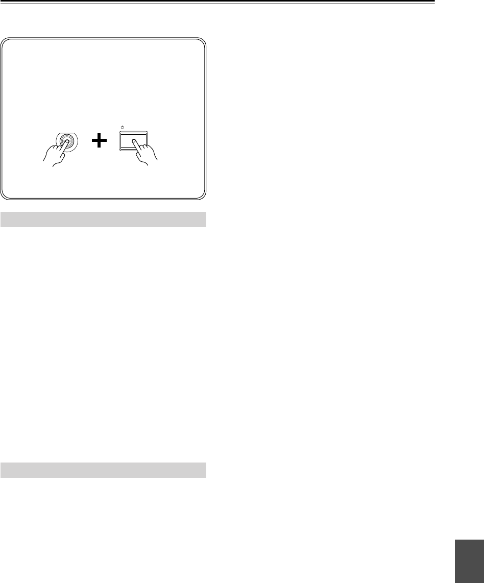
61
Troubleshooting
If you have any trouble using the 7.1ch Home Theater
System, look for a solution in this section.
Can’t turn on the AV receiver
•Make sure that the power cord is plugged into the wall
outlet properly.
• Unplug the power cord from the wall outlet, wait 5
seconds or more, then plug it in again.
The AV receiver turns off as soon as it’s turned
on
• The amp protection circuit has been activated.
Remove the power cord from the wall outlet immedi-
ately. Disconnect all speaker cables and input sources,
and leave the AV receiver with its power cord discon-
nected for 1 hour. After that, reconnect the power cord
and set the volume to maximum. If the AV receiver
stays on, set the volume to minimum, disconnect the
power cord, and reconnect your speakers and input
sources. If the AV receiver turns off when you set the
volume to maximum, disconnect the power cord, and
contact your Onkyo dealer.
There’s no sound or it’s very quiet
• Make sure that the digital input source is selected
properly (page 35). Press the [DIGITAL INPUT] but-
ton repeatedly.
• Make sure the speker set A or B is on (page 5).
•Make sure that all audio connecting plugs are pushed
in all the way (page 22).
• Make sure that the polarity of the speaker cables is
correct, and that the bare wire is in contact with metal
part of each speaker terminal (page 19)
• Make sure that the speaker cables are not shorting.
•Check the volume. It can be set to MIN, 1 through 79,
or MAX (page 36). The AV receiver is designed for
home theater enjoyment and has a wide volume range
for precise adjustment.
• If the MUTING indicator is shown on the display,
press the remote controller’s [MUTING] button to
unmute the AV receiver (page 44).
• While a pair of headphones is connected to the
PHONES jack, no sound is output by the speakers
(page 45).
• Check the digital audio output settings on the con-
nected device. On some games consoles, such as those
that can play DVDs, the default setting is off.
•With some DVD-Video discs, you need to select an
audio format from a menu.
•If your turntable doesn’t have a phono preamp built-in,
you must connect one between it and the AV receiver.
If your turntable uses an MC cartridge, you must con-
nect an MC head amp, or an MC transformer and a
phono preamp.
•Specify the speaker distances and adjust the individual
speaker levels (pages 52, 53).
•The input signal format is set to PCM or DTS. Set it to
Auto (page 56).
Only the front speakers produce sound
• When the Stereo or Mono listening mode is selected,
only the front speakers and subwoofer produce sound.
• Make sure the speakers are configured correctly
(page 54).
Only the center speaker produces sound
• If you use the Pro Logic IIx Movie, Pro Logic IIx
Music, or Pro Logic IIx Game listening mode with a
mono source, such as an AM radio station or mono TV
program, the sound is concentrated in the center
speaker.
• Make sure the speakers are configured correctly
(page 54).
The surround speakers produce no sound
• When the Stereo or Mono listening mode is selected,
the surround speakers produce no sound (page 48).
• Depending on the source and current listening mode,
not much sound may be produced by the surround
speakers. Try selecting another listening mode.
• Make sure the speakers are configured correctly
(page 54).
The center speaker produces no sound
• When the Stereo or Mono listening mode is selected,
the center speaker produces no sound (page 48).
• Make sure the speakers are configured correctly
(page 54).
The surround back speakers produce no sound
•While speaker set B is on, speaker set A is reduced to
5.1-channel playback and the surround back speakers
produce no sound.
Power
Audio
If you can’t resolve the issue yourself, try resetting
the AV receiver before contacting your Onkyo dealer.
To reset the AV receiver to its factory defaults,
turn it on and, while holding down the [VIDEO 1]
button, press the [STANDBY/ON] button. “Clear”
will appear on the display and the AV receiver will
enter Standby mode.
Note that resetting the AV receiver will delete your
radio presets and custom settings.
STANDBY/ON
VIDEO 1
VCR
HT-S790_En.book Page 61 Friday, February 17, 2006 3:28 PM

62
Troubleshooting
—Continued
• The surround back speakers are not used with all lis-
tening modes. Select another listening mode
(page 48).
• Not much sound may be produced by the surround
back speakers with some sources.
• Make sure the speakers are configured correctly
(page 54).
The subwoofer produces no sound
• The level of the input signal was too low so the sub-
woofer entered Standby mode. Increase the subwoofer
level slightly on the HT-R540.
• Make sure that the subwoofer’s [POWER] switch is
set to ON (not North American models).
• The subwoofer’s OUTPUT LEVEL control is set at
minimum. Turn it up.
• The subwoofer outputs no sound while only speaker
set B is on. Turn on speaker set A.
•When you play source material that contains no infor-
mation in the LFE channel, the subwoofer produces
no sound.
• Make sure the speakers are configured correctly
(page 54).
Speaker set B produces no sound
•Speaker set B only outputs sources that are connected
to an analog input. Make sure that the analog audio
cables are connected properly.
There’s no sound with a certain signal format
• Check the digital audio output setting on the con-
nected device. On some games consoles, such as those
that can play DVDs, the default setting is off.
•With some DVD-Video discs, you need to select an
audio output format from a menu.
Can’t get 6.1- or 7.1-channel playback
•While speaker set B is on, speaker set A is reduced to
5.1-channel playback.
The volume cannot be set to 79
• When the volume level of each speaker has been
adjusted (pages 45, 53), the maximum possible vol-
ume may be reduced.
Noise can be heard
• Using cable ties to bundle audio cables with power
cords, speaker cables, and so on may degrade the
audio performance, so don’t do it.
• An audio cable may be picking up interference. Try
repositioning your cables.
The Late Night function doesn’t work
• Make sure the source material is Dolby Digital
(page 50).
The multichannel DVD input doesn’t work
• Check the multichannel DVD input connections
(page 26).
•To select the multichannel DVD input, press the
[MULTI CH] input selector button.
• Check the audio output settings on your DVD player.
About DTS signals
•When playing DTS program material, using the pause,
fast forward, or fast reverse function on your player
may produce a short audible noise. This is not a mal-
function.
• When DTS program material ends and the DTS bit-
stream stops, the AV receiver remains in DTS listen-
ing mode and the DTS indicator remains on. This is to
prevent noise when you use the pause, fast forward, or
fast reverse function on your player. If you switch your
player from DTS to PCM, because the AV receiver
does not switch formats immediately, you may not
hear any sound, in which case you should stop your
player for about 3 seconds, and then resume playback.
•With some CD players, you won’t be able to playback
DTS material properly even though your player is con-
nected to a digital input on the AV receiver. This is
usually because the DTS bitstream has been processed
(e.g., output level, sampling rate, or frequency
response changed) and the AV receiver doesn’t recog-
nize it as a genuine DTS signal. In such cases, you
may hear noise.
There’s no picture
•Make sure that all video connecting plugs are pushed
in all the way (page 22).
•Make sure that each video component is properly con-
nected.
•The AV receiver does not convert between formats, so
if a video source component is connected to a compo-
nent video input, your TV must be connected to the
component video output (page 23).
• On your TV, make sure that the video input to which
the AV receiver is connected is selected.
• While the Pure Audio listening mode (not North
American model) is selected, the video circuits are
turned off and the AV receiver outputs no video sig-
nals.
Video
HT-S790_En.book Page 62 Friday, February 17, 2006 3:28 PM
63
Troubleshooting
—Continued
Reception is noisy, stereo FM reception suffers
from hiss, or the FM STEREO indicator doesn’t
appear
• Relocate your antenna.
•Move the AV receiver away from your TV or com-
puter.
• Listen to the station in mono (page 38).
•When listening to an AM station, operating the remote
controller may cause noise.
•Passing cars and airplanes can cause interference.
• Concrete walls weaken radio signals.
• If nothing improves the reception, install an outdoor
antenna.
The remote controller doesn’t work
•Make sure that the batteries are installed with the cor-
rect polarity (page 13).
• Make sure that the remote controller is not too far
away from the AV receiver, and that there’s no
obstruction between the remote controller and the AV
receiver’s remote control sensor (page 13).
•Make sure you’ve selected the correct remote control-
ler mode (page 14).
• Make sure you’ve entered the correct remote control
code (page 58).
Can’t control other components
•Make sure you’ve selected the correct remote control-
ler mode (page 14).
• If you’ve connected an -capable Onkyo MD
recorder, CD recorder, or next generation HDD-com-
patible component to the TAPE IN/OUT jacks, or a
DS-A1 Remote Interactive Dock to the VIDEO 2 IN
jacks, for the remote controller to work properly, you
must set the Input Display to MD, CDR, or HDD (see
page 35).
•The entered remote control code may not be correct. If
more than one code is listed, try each one.
•With some AV components, certain buttons may not
work as expected, and some may not work at all.
•To control an Onkyo component that’s connected via
, point the remote controller at the AV receiver. Be
sure to enter the appropriate remote control code first
(see page 59).
•To control an Onkyo component that’s not connected
via , or another manufacturer’s component, point
the remote controller at the component. Be sure to
enter the appropriate remote control code first (see
page 58).
Can’t record
• On your recorder, make sure the correct input is
selected.
•To prevent signal loops and damage to the AV
receiver, input signals are not fed through to outputs
with the same name (e.g., TAPE IN to TAPE OUT, or
VIDEO 1 IN to VIDEO 1 OUT).
• When the Pure Audio listening mode is selected,
recording is not possible because no video signals are
output. Select another listening mode.
The sound changes when I connect my head-
phones
•When a pair of headphones is connected, the listening
mode is set to Stereo, unless it’s already set to Stereo,
Mono, Direct, or Pure Audio (not North American
model).
The display doesn’t work
• The display is turned off when the Pure Audio (not
North American model) listening mode is selected.
How do I change the language of a multiplex
source
• Use the “Multiplex” setting on the “4. Audio Adjust”
menu to select Main or Sub (page 51).
The functions don’t work
•To use , you must make an connection and an
analog audio connection (RCA) between the compo-
nent and AV receiver, even if they are connected digi-
tally (page 33).
Tuner
Remote Controller
Recording
Others
HT-S790_En.book Page 63 Friday, February 17, 2006 3:28 PM

64
Troubleshooting
—Continued
The following settings can be made for the
S-Video and composite video inputs
You must use the buttons on the unit to make these set-
tings.
1. While holding down the input selector button for the
input source that you want to set, press the [SETUP]
button.
2. Use the Up and Down [ ]/[ ] buttons to select a
setting (see below).
3. Use the Left and Right [ ]/[ ] buttons to change
the setting:
4. Press the [SETUP] button when you’ve finished.
•
Video Attenuation
This setting can be made for the DVD, VIDEO 1,
VIDEO 2, or VIDEO 3 input.
If you have a games console connected to an S-Video
or composite video input, and the picture isn’t very
clear, you can attenuate the gain.
Video ATT:0:
(default).
Video ATT:2:
Gain is reduced by 2 dB.
•
Outputting S-Video Sources from the Composite
Video Outputs
This setting can be made for the DVD, VIDEO 1, or
VIDEO 2 input.
With this setting, you can output S-Video input
sources from the composite video outputs, useful if
your TV doesn’t have any S-Video inputs.
Y/C Mix:Off:
S-Video input signals are output by
only S-Video outputs (default).
Y/C Mix:On:
S-Video input signals are output by
S-Video outputs and composite video outputs.
The AV receiver contains a microcomputer for signal pro-
cessing and control functions. In very rare situations,
severe interference, noise from an external source, or
static electricity may cause it to lockup. In the unlikely
event that this happens, unplug the power cord from the
wall outlet, wait at least five seconds, and then plug it
back in again.
Onkyo is not responsible for damages (such as CD
rental fees) due to unsuccessful recordings caused by
the unit’s malfunction. Before you record important
data, make sure that the material will be recorded cor-
rectly.
Before disconnecting the power cord from the wall out-
let, set the AV receiver to Standby.
Memory Backup
The AV receiver uses a battery-less memory backup
system in order to retain radio presets and other set-
tings when it’s unplugged or in the case of a power fail-
ure. Although no batteries are required, the AV receiver
must be plugged into an AC outlet in order to charge the
backup system. Once it has been charged, the AV
receiver will retain the settings for several weeks,
although this depends on the environment and will be
shorter in humid climates.
HT-S790_En.book Page 64 Friday, February 17, 2006 3:28 PM

65
Specifications
Amplifier Section
Video Section
Tuner Section
■
FM
■
AM
General
■
Video Inputs
■
Video Outputs
■
Audio Inputs
■
Audio Outputs
Rated Output Power (FTC)
All channels: 110 watts minimum continuous power
per channel, 8 ohm loads, 2 channels
driven at 1 kHz, with a maximum total
harmonic distortion of 0.9%
Rated Output Power (IEC)
7 ch
×
130 W at 8 ohms, 1 kHz, 1 ch
driven
Maximum Output Power (JEITA)
7 ch
×
160 W at 8 ohms, 1 kHz, 1 ch
driven
Dynamic Power 230 W + 230 W (3
Ω
, Front)
170 W + 170 W (4
Ω
, Front)
120 W + 120 W (8
Ω
, Front)
THD (Total Harmonic
Distortion) 0.08% (Power Rated)
Damping Factor 60 (Front, 1kHz, 8
Ω
)
Input Sensitivity and
Impedance 200 mV/ 47 k
Ω
(LINE)
Output Level and
Impedance 200 mV/ 470
Ω
(REC OUT)
Frequency Response 5 Hz–100 kHz/ +1 dB–3 dB (Direct mode)
Tone Control ±10 dB, 80 Hz (BASS)
±10 dB, 20 kHz (TREBLE)
Signal to Noise Ratio 100 dB (LINE, IHF-A)
Speaker Impedance 8
Ω
–16
Ω
Input Sensitivity/Output
Level and Impedance 1 Vp-p /75
Ω
(Component and S-Video Y)
0.7 Vp-p /75
Ω
(Component P
B
/C
B
, P
R
/C
R
)
0.28 Vp-p /75
Ω
(S-Video C)
1 Vp-p /75
Ω
(Composite)
Component Video
Frequency Response 5 Hz–50 MHz
Tuning Frequency
Range North American: 87.5 MHz–107.9 MHz
Other: 87.5 MHz–108.0 MHz
Usable Sensitivity Stereo: 22.2 dBf (75
Ω
IHF)
Mono: 15.2 dBf (75
Ω
IHF)
Signal to Noise Ratio Stereo: 67 dB (IHF-A)
Mono: 73 dB (IHF-A)
THD Stereo: 0.5% (1 kHz)
Mono: 0.3% (1 kHz)
Frequency Response 30 Hz–15 kHz / ±1 dB
Stereo Separation 40 dB (1 kHz)
Tuning Frequency
Range North American: 530 kHz–1710 kHz
Others: 522/530 kHz–1611/1710 kHz
Usable Sensitivity 300 µV
Signal to Noise Ratio 40 dB
THD 0.7%
Power Supply North American: AC 120 V, 60 Hz
Others: AC 230-240 V, 50Hz
Power Consumption North American: 5.9 A
Others: 670 W
Standby Power
Consumption North American: 0.1 W
Others: 0.5 W
Dimensions
(W
×
H
×
D)
435
×
151
×
377 mm
17-1/8"
×
5-15/16"
×
14-13/16"
Weight North American: 9.6 kg
21.2 lbs.
Others: 10.2 kg
22.5 lbs.
Component DVD, VIDEO1, VIDEO2
S-Video DVD, VIDEO1, VIDEO2
Composite DVD, VIDEO1, VIDEO2, VIDEO3
Component MONITOR
S-Video MONITOR, VIDEO1
Composite MONITOR, VIDEO1
Digital Inputs Optical: 3
Coaxial: 1
Analog Inputs DVD (MULTICHANNEL), VIDEO1,
VIDEO2, VIDEO3, TAPE, CD
Multichannel Inputs 7.1
Analog Outputs TAPE, VIDEO1
Subwoofer Pre Outputs 1
Speaker Outputs SP A (L, R, C, SL, SR, SBL, SBR)
SP B (L, R)
Phones 1
HT-S790_En.book Page 65 Friday, February 17, 2006 3:28 PM

66
Specifications
—Continued
■
Powered Subwoofer (SKW-540)
■
Front Speaker (SKF-540F)
■
Center Speaker (SKC-540C)
■
Surround Speaker (SKM-540S/SKB-540)
Specifications and appearance are subject to change
without prior notice.
■
Speaker
Type: Bass-reflex
Input
sensitivity/impedance: 330 mV / 100 k
Ω
Maximum output power:230 W (Dynamic Power)
Frequency response: 25 Hz–150 Hz
Cabinet capacity: 1.36 cubic feet (38.5 L)
Dimensions
(W
×
H
×
D):
10-13/16"
×
18-5/8"
×
17-11/16"
(275
×
473
×
449 mm)
Weight: 25.4 lbs. (11.5 kg)
Drivers unit: 10 inch (25 cm) Cone Woofer
Power supply: North American: AC 120 V, 60 Hz
Australian: AC 230-240 V, 50 Hz
Power consumption: North American: 140 W
Australian: 137 W
Other: Auto Standby function
Type: 2 Way Bass-reflex
Impedance: 8
Ω
Maximum input power: 130 W
Output sound pressure
level:
86 dB/W/m
Frequency response: 55 Hz–50 kHz
Crossover frequency: 4.5 kHz
Cabinet capacity: 0.28 cubic feet (8.0 L)
Dimensions
(W
×
H
×
D):
6-3/16"
×
17-1/16"
×
7-7/8"
(157
×
433
×
200 mm)
Weight: 8.4 lbs. (3.8 kg)
Drivers unit: 5 inch (12 cm) OMF Cone Woofer
×
2
1 inch (2.5 cm) Balanced Dome Tweeter
Terminal: Color-coded push type
Other: Magnetic shielding
Type: 2 Way Bass-reflex
Impedance: 8
Ω
Maximum input power: 130 W
Output sound pressure
level:
86 dB/W/m
Frequency response: 55 Hz–50 kHz
Crossover frequency: 4.5 kHz
Cabinet capacity: 0.28 cubic feet (8.0 L)
Dimensions
(W
×
H
×
D):
17-1/16"
×
6-3/16"
×
7-7/8"
(433
×
157
×
200 mm)
Weight: 8.4 lbs. (3.8 kg)
Speaker: 5 inch (12 cm) OMF Cone Woofer
×
2
1 inch (2.5 cm) Balanced Dome Tweeter
Terminal: Color-coded push type
Other: Magnetic shielding
Type: 2 Way Bass Reflex
Impedance: 8
Ω
Maximum input power: 130 W
Output sound pressure
level:
82 dB/W/m
Frequency response: 60 Hz–20 kHz
Crossover frequency: 10 kHz
Cabinet capacity: 0.07 cubic feet (2.1 L)
Dimensions
(W
×
H
×
D): 6-7/8"
×
10-7/16"
×
4"
(175
×
265
×
102 mm)
Weight: 3.1 lbs. (1.4 kg)
Speaker: 3-1/8 inch (8 cm) Cone Woofer
3/4 inch (2 cm) Ceramic Tweeter
Terminal: Color-coded push type
HT-S790_En.book Page 66 Friday, February 17, 2006 3:28 PM

67
Memo
HT-S790_En.book Page 67 Friday, February 17, 2006 3:28 PM

68
SN 29344189
I0602-1
Sales & Product Planning Div. : 2-1, Nisshin-cho, Neyagawa-shi, OSAKA 572-8540, JAPAN
Tel: 072-831-8023 Fax: 072-831-8124
ONKYO U.S.A. CORPORATION
18 Park Way, Upper Saddle River, N.J. 07458, U.S.A.
Tel: 201-785-2600 Fax: 201-785-2650 http://www.us.onkyo.com/
ONKYO EUROPE ELECTRONICS GmbH
Liegnitzerstrasse 6, 82194 Groebenzell, GERMANY
Tel: +49-8142-4401-0 Fax: +49-8142-4401-555 http://www.eu.onkyo.com/
ONKYO EUROPE UK Office
Suite 1, Gregories Court, Gregories Road, Beaconsfield, Buckinghamshire, HP9 1HQ
UNITED KINGDOM Tel: +44-(0)1494-681515 Fax: +44(0)-1494-680452
ONKYO CHINA LIMITED
Units 2102-2107, Metroplaza Tower I, 223 Hing Fong Road, Kwai Chung,
N.T., HONG KONG Tel: 852-2429-3118 Fax: 852-2428-9039
http://www.ch.onkyo.com/
(C) Copyright 2006 ONKYO CORPORATION Japan. All rights reserved.
http://www.onkyo.com/
HOMEPAGE
* 2 9 3 4 4 1 8 9 *
HT-S790_En.book Page 68 Friday, February 17, 2006 3:28 PM

C
s
C
t
Fr
S
v
D
e
E
s
En
It
N
l
Remote Control Codes
1. While holding down the REMOTE
MODE button that you want to set,
press the [DISPLAY] button for 3
seconds.
2. Use the number buttons to enter the
4-digit remote control code.
Codes de télécommande
1. Maintenez le bouton REMOTE MODE à
initialiser enfoncé et appuyez sur le bouton
[DISPLAY] durant 3 secondes.
2. Entrez les 4 chiffres du code de télécommande avec
les boutons numériques.
Codici del telecomando
1. Mentre tenete premuto il pulsante REMOTE
MODE che volete impostare, premete il pulsante
[DISPLAY] per 3 secondi.
2. Utilizzate i pulsanti numerici per inserire il codice di
telecomando a 4 cifre.
Afstandsbedieningscodes
1. Houd de REMOTE MODE toets ingedrukt die u
wilt instellen en druk dan de [DISPLAY] toets 3
seconden in.
2. Met de cijfertoetsen de 4-cijferige
afstandsbedieningscode in.
遙控代碼
1. 按下您希望設置的遙控鍵,同時按下 [DISPLAY]
鍵保持 3 秒鐘。
2. 使用數字鍵輸入 4 位數字的遙控代碼。
Códigos de control remoto
1. Manteniendo pulsado el botón REMOTE MODE
que desee ajustar, pulse el botón [DISPLAY]
durante 3 segundos.
2. Utilice los botones de número para introducir el
código de 4 dígitos para control remoto.
Fernbedienungscodes
1. Halten Sie die änderungsbedürftige REMOTE
MODE-Taste gedrückt, während Sie die
[DISPLAY]-Taste 3 Sekunden lang betätigen.
2. Geben Sie mit den Zifferntasten den 4-stelligen
Fernbedienungscode ein.
Fjärrstyrningskoder
1. Tryck in och håll lämplig lägesväljare (REMOTE
MODE) intryckt och tryck samtidigt in knappen
[DISPLAY] i tre sekunder.
2. In den 4-siffriga fjärrstyrningskoden med hjälp av
sifferknapparna.
遙控代碼
1. 按下您希望設置的遙控鍵,同時按下 [DISPLAY]
鍵保持 3 秒鐘。
2. 使用數字鍵輸入 4 位數字的遙控代碼。
M
D/CDR
HDD
CABLE
REMOTE MODE
SAT
VCR
TV
DVD
C
D
DISPLAY
0
123
456
789
Remocon Codes.fm Page 1 Tuesday, March 7, 2006 9:25 AM

2
DVD Codes DVD
DVD Player
Acoustic Solutions 0730, 0713
Advent 1016
Aiwa 0641
Akai 0899, 1115
Akura 0898
Amoisonic 0835
Amphion Media
Works 0872
Amstrad 0713
AMW 0872
Apex Digital 0755, 0794, 0830,
1020, 1061
Aspire Digital 1168
Audiovox 1071, 1121, 1122
Axion 1071, 1193
Blue Nova
International 1321
Broksonic 1419
Bush 0516, 0690, 0713
Cambridge
Soundworks 0690
Celestial 1020
Changhong 0627, 1061
CineVision 0833, 1483
Clayton 0713
Coby 0852, 1086,
1321, 1351
Conia 0835
CyberHome 0714, 0874, 1023,
1129
Daewoo 0714, 0833
Daytek 0872
Denver 0898, 1321
Diamond 0768
Dick Smith
Electronics 0833, 1483
Digitor 0690
Disney 0675
DSE 0833, 1483
DVD2000 0521
ECC 0730
Elta 1115
Eltax 1321
Emerson 0675, 0821, 1268
Ferguson 0898
Funai 0675, 1268, 1334
Gateway 1073
GE 0815
Go Video
0715, 0833, 1044,
1075, 1099, 1304,
1483
Go Vision 1071
H & B 0818, 0841, 1233,
1421
Harman/Kardon 0582
Hitachi 1247, 1664
iLo 1348
Integra 0627
Jensen 1016
JVC 0558
jWin 1051
Kiss 0841, 1523
KLH 1020, 1261
Kreisen 1421
KXD 1321
Lecson 1533
Lenoxx 0838
LG 0801
Limit 0768
LiteOn 1058, 1416, 1440
Loewe 0511
Lumatron 1321
Magnavox 0675, 0821, 1140,
1268
McIntosh 1533
Medion 1347
Memorex 0690
Metronic 0690
Mitsubishi 1521, 0521, 1403
Mustek 0730
NEC 0785, 1404
Nintaus 1051
Norcent 1003, 0872
Onkyo 0627, 1612(RI)
Orion 1419
Palsonic 0835, 0852
Panasonic
0703, 1010, 1011,
1362, 1462, 1490,
1762
Philco 0690
Philips 0675, 0854, 1260,
1340, 1354
Pioneer 0525, 0631
Polaroid 1020, 1061, 1086
Prima 1016
ProVision 1321
RCA 0822, 1022, 1132,
1193
Redstar 0898
Relisys 1347
Roadstar 1051
Sampo 1321
Samsung 0820, 0899, 1044,
1075
Santosh 1115
Sanyo 0873
Sharp 0675, 1256, 1419
Skyworth 0898
Sliding 1115
SM Electronic 0730, 0690
Sonic Blue 1099
Sony 1533, 1033, 1069,
1070, 1431
Sova 1122
Superscan 0821
Sylvania 0675, 0821, 1268
Symphonic 0675, 1268
Tangent 1321
Teac
0516, 0759, 0809,
0833, 1006, 1021,
1483
Technics 0703
Technosonic 0730
Tedelex 0690
Tevion 1036, 1227, 1382
DVD Player
Thomson 0551
Toshiba 1045, 1154, 1510
TRANS-continents 1321
Umax 0690
Vizio 1064
Yamada 0872, 1416
Yamaha 0545
Yamakawa 0872
DVD Recorder
Aspire Digital 1168
Coby 1086
CyberHome 1129
Eltax 1321
Funai 0675, 1334
Gateway 1073
Go Video 1304
H & B 1421
Hitachi 1664
iLo 1348
Kreisen 1421
LiteOn 1416, 1440
Medion 1347
Mitsubishi 1403
NEC 1404
Panasonic 1010, 1011
Pioneer 0631
Polaroid 1086
Relisys 1347
Sharp 0675, 1419
Sony 1033, 1069, 1070,
1431
Sylvania 0675
Tangent 1321
Tevion 1227
Thomson 0551
Toshiba 1510
Yamada 1416
TV/DVD Combination
Advent 1016
Apex Digital 0830
Audiovox 1071, 1121, 1122
Axion 1071, 1193
Bush 0516, 0713
Emerson 0675, 1268
Go Vision 1071
Hitachi 1247
Jensen 1016
KLH 1261
Magnavox 1268
Panasonic 1490
Philips 0854, 1260
Prima 1016
RCA 1022, 1193
Samsung 0899
Sliding 1115
Sova 1122
Sylvania 0675, 1268
Teac 1021
DVD Player
Remocon Codes.fm Page 2 Tuesday, March 7, 2006 9:25 AM

3
CD/MD/CDR/HDD Codes
M
D/CDR
HDD
C
D
CD Player
Anthem 0897
Bush 0388
Carver 0179
Classic 1297
Copland 0393
Denon 0034, 0766
Dynamic Bass 0179
Fisher 0179, 1325
Garrard 0393
Genexxa 0426
GoldStar 1208
GPX 1296
Harman/Kardon 0173, 0426, 1202
HHB 0192
Inkel 0180
JVC 1294
Kenwood 0826, 0028, 0037
KLH 1373
LG 1208
Magnavox 0038
Marantz 0038, 0180, 0435
Memorex 0180
Musical Fidelity 0393
NAD 0721, 1208
Onkyo 1327(RI), 1817
Optimus 1063, 0037, 0468,
0087, 0179, 0426
Panasonic 0388, 0752
Philips 0274
Pioneer 1063, 1062, 1087,
0468, 0192
RCA 1062, 0468, 0053,
0179
Realistic 0179, 0180
Roksan 0435
Rotel 0897
Sanyo 0087, 0179
Sharp 0861, 0037, 0034,
0180
Sherwood 1067, 0180, 0426
Silsonic 0888
Sony 0100, 1364, 0185
TDK 1208
Teac 0393, 0180, 0435
Technics 0207, 1078
Thomson 0053
Universum 0053
Wards 0053
Yamaha 0888, 1292
CD Recorder
Classic 1297
Denon 0766
Fisher 1325
GPX 1296
Harman/Kardon 1202
HHB 0192
JVC 1294
KLH 1373
LG 1208
NAD 1208
Onkyo 1322(RI), 1323
Pioneer 1062, 1087, 0192
RCA 0053
Sony 0100, 1364
TDK 1208
Yamaha 0888, 1292
MD Recorder
Kenwood 0826
Onkyo 0868, 1808(RI)
Optimus 1063
Pioneer 1063
Sharp 0861
Sherwood 1067
Sony 0185
Technics 1078
Yamaha 0888
HDD Player
Onkyo 1990, 1993(RI)
Remocon Codes.fm Page 3 Tuesday, March 7, 2006 9:25 AM

4
TV Codes TV
TV
888 0264
Acura 0009
Addison 0653, 0108, 0092,
1150
Admiral 0463, 0163
Advent 0761, 0783, 0815,
0842
Aiko 0092
Aiwa 0701, 1180
Akai
0060, 0812, 0702,
0030, 0264, 0218,
0009, 0208, 0672,
0729, 0745, 0753,
1207
Akura 0264, 0218
Alba 0037, 0218, 0009,
0371
Albatron 0700
Alfide 0672
America Action 0180
Amstrad 0171, 0037, 0009,
0371
Anam 0250, 0180, 0009,
0161, 0700
Anam National 0250, 0161
Anhua 0051
Anitech 0009
AOC
0451, 0180, 0060,
0030, 0108, 0009,
0092, 1150
Aolinpike 0264
Apex Digital 0156, 0748, 0765,
0767, 0879, 1217
Asuka 0218
Audinac 0180
Audiosonic 0037, 0109
Audiovox 0451, 0180, 0092,
0623, 0802
Aventura 0171
Awa 0009
Baihe 0264, 0009
Baile 0001, 0009, 0374,
0661
Baird 0343
Bang & Olufsen 0565
Baohuashi 0264
Baosheng 0009
Basic Line 0218, 0009
Baur 0037, 0512
Baysonic 0180
Beijing
0812, 0264, 0226,
0001, 0009, 0208,
0374, 0661
Beko 0714, 0370
Bell & Howell 0154
BenQ 1032
Beon 0037
Blaupunkt 0195
Blue Sky 0556, 0218, 1254
BPL 0896
Bradford 0180
Brandt 0109, 0335
Broksonic 0236, 0463, 0180
BTC 0218
Bush 0037, 0698, 0218,
0009, 0371, 0374
Caihong 0009
Cailing 0748
Candle 0030, 0056
Carnivale 0030
Carver 0054, 0170
Cascade 0009
Cathay 0037
CCE 0037
Celebrity 0000
Celera 0765
Celestial 0767
Centrex 0780
Centurion 0037
Changcheng 0051, 0264, 0001,
0009, 0374, 0661
Changfei 0009, 0374
Changfeng 0264, 0753
Changhai 0009
Changhong
0156, 0765, 0264,
0508, 0009, 0767,
0783, 1156
Chengdu 0009
Ching Tai 0009, 0092
Chun Yun
0000, 0180, 0009,
0092, 0161, 0700,
1150
Chunfeng 0264, 0009
Chung Hsin 0180, 0053, 0108,
1150
Chunsun 0009
Cimline 0009
Cinema 0672
Cineral 0451, 0092
Citizen 0060, 0030, 0056,
0092
Clarion 0180
Clarivox 0037
Clatronic 0370
Commercial
Solutions 0047, 1447
Concerto 0056
Condor 0370
Conrowa
0156, 0145, 0698,
0264, 0009, 0753,
1156
Contec 0180, 0009
Craig 0180, 0161
Crosley 0054
Crown 0180, 0037, 0370,
0009, 0418, 0672
Crown Mustang 0672
Curtis Mathes
0047, 0054, 0154,
0451, 0060, 0702,
0030, 0145, 0166,
0056, 1147, 1347
CXC 0180
TV
Cybertron 0218
Daewoo
0154, 0451, 0180,
0030, 0037, 0634,
0108, 1150, 0880,
0700, 0672, 0661,
0623, 0374, 0170,
0092, 0056, 0009
Dainichi 0218
Dansai 0037
Dayton 0009
Dayu 0374, 0661
De Graaf 0548, 0208
Decca 0037
Dell 1454, 1080
Denon 0145, 0511
Dick Smith
Electronics 0698
Digatron 0037
Digital Life 0780
Digitor 0037, 0698
Digix 0880
Dixi 0037, 0009
Dongda 0009
Donghai 0009
DSE 0698
Dumont 0017
Durabrand 0463, 0180, 0171
ECE 0037
Electroband 0000
Elektra 0017
Elin 0037, 0548
Elite 0218
Elta 0009
Emerson
0154, 0451, 0236,
0463, 0180, 0171,
0623
Envision 0030
Erres 0037
ESA 0812, 0171
Ether 0030, 0009, 0161
Etron 0009
Feilang 0009
Feilu 0009
Feiyan 0264
Feiyue 0009
Ferguson 0037, 0560, 0109,
0335, 0343
Finlandia 0208, 0346
Finlux 0037, 0105, 0346
Firstar 0236, 0009
Firstline 0009
Fisher 0154, 0370, 0208
Formenti 0037
Frontech 0264, 0163
Fujitsu 0809, 1181
Funai 0180, 0171, 0264,
0342
Furi 0145, 0264
Futuretech 0180
TV
Remocon Codes.fm Page 4 Tuesday, March 7, 2006 9:25 AM

5
TV
GE
0047, 0051, 0451,
0180, 0030, 1447,
1454, 0560, 0092,
1147, 1347
GEC 0037
Geloso 0009
Genexxa 0218, 0163
Gibralter 0017, 0030
Gintai 1150
Go Video 0886
GoldStar
0154, 0030, 0037,
0001, 0056, 0109,
1150, 1378
Goodmans 0037, 0634, 0343,
0360, 0371, 0374
Gorenje 0370
GPM 0218
Gradiente 0053, 0056, 0170
Graetz 0714, 0163
Granada 0037, 0208
Grandin 0610, 0880
Grundig 0556, 0037, 0195,
0487, 0672
Grunpy 0180
Haier 0037, 0698, 0508,
0896
Haihong 0009
Haiyan 0264
Hankook 0180, 0030, 0056
Hanseatic 0556, 0037, 0661
Harman/Kardon 0054
Harvard 0180
Harwa 0773
HCM 0009
Hello Kitty 0451
Himitsu 0180
Hinari 0037, 0218, 0009
Hisense
0156, 0748, 0145,
0556, 0508, 0009,
0753, 0780, 1156
Hitachi
0156, 0030, 1145,
0145, 1256, 0548,
0225, 0508, 1378,
1245, 1156, 1150,
1149, 0744, 0578,
0577, 0481, 0163,
0109, 0105, 0092,
0056, 0009
Hongmei 0264, 0009
Hongyan 0264
Hua Tun 0009, 1150
Huafa 0145, 0009
Huanghaimei 0009
Huanghe 0009
Huanglong 0009
Huangshan 0264, 0009
Huanyu 0264, 0374
Huaqiang 0264
Huari 0145, 0264
Huodateji 0051
Hypson 0037, 0264
ICE 0264, 0371
ICeS 0218
Imperial 0370, 0418
Imperial Crown 0264, 0001, 0009,
0374, 0661
Indiana 0037
Infinity 0054
Ingelen 0163
Innova 0037
Inteq 0017
Interfunk 0037, 0163, 0512
Intervision 0037, 0264
IRT 0451, 0698
Isukai 0218
ITS 0371
ITT 0548, 0163
IX 0877
JBL 0054
JCB 0000
Jean 0156, 0051, 0236,
0009, 0092
Jensen 0761, 0815
Jiahua 0051
JiaLiCai 0264, 0009
Jinfeng 0051, 0226, 0208
Jinque 0264, 0009
Jinta 0264, 0009
Jinxing
0054, 0156, 0145,
0556, 0037, 0698,
0264, 0009
Juhua 0264
JVC
0463, 0053, 0606,
0653, 0508, 0160,
0371, 1172, 1253
Kaige 0264, 0009
Kaisui 0218, 0009
Kanghua 0896
Kangli 0264, 0001, 0009,
0374, 0661
Kangyi 0264, 0009
Kapsch 0163
Karcher 0610
Kathrein 0556
KEC 0180
Kendo 0037
Kenwood 0030
Kioto 0054, 0556
KLH 0765, 0767
KLL 0037
Kolin 0180, 0150, 0053,
0108, 1150
Kongque 0264, 0009
Konka 0037
Korpel 0037
Koyoda 0009
KTV 0180, 0030
Kuaile 0264, 0009
Kulun 0009
Kunlun 0051, 0264, 0226,
0208, 0374, 0661
Leyco 0037, 0264
TV
LG
1265, 0060, 0030,
0037, 0714, 0108,
0001, 0056, 0442,
0644, 0700, 0856,
1148, 1378
Liesenk & Tter 0037
Local India TV 0264, 0371
Loewe 0136, 0512, 0633,
0790
Logik 0001, 1217
Longjiang 0264
Luxman 0056
LXI 0047, 0054, 0154,
0156
M & S 0054
M Electronic
0037, 0009, 0105,
0109, 0163, 0346,
0374, 0480
Magnavox 0054, 0030, 1454,
0780, 0802, 1254
Manesth 0264
Marantz 0054, 0030, 1454,
0556, 0037, 0855
Mark 0037
Matsui 0037, 0487, 0009,
0035, 0208, 0371
Matsushita 0250, 0161
Mediator 0037
Medion 0880, 1248
Megapower 0700
Megatron 0145
Meile 0264
Memorex 0154, 0463, 0150,
0009
Mercury 0001
Mermaid 0037
Metronic 0625
MGA 0150, 0030
Midland 0047, 0017, 0051
Minerva 0487
Mitsubishi
0154, 0250, 0236,
0180, 0150, 1250,
0030, 0108, 0056,
0512, 0836, 1150,
1171, 1182
Monivision 0700
MTC 0060, 0030, 0056,
0512
Mudan 0051, 0264, 0226,
0009, 0208
Multitech 0180, 0009
Myryad 0556
NAD 0156, 0866
Nanbao 0264, 0009
Nansheng 0264
National 0051, 0226, 0508,
0208
TV
Remocon Codes.fm Page 5 Tuesday, March 7, 2006 9:25 AM

6
TV Codes TV
TV
NEC
0154, 0156, 0051,
0053, 0030, 0264,
0508, 0009, 0056,
0170, 1150, 1182,
1378, 1456
Neckermann 0556, 0037
NEI 0037
Netsat 0037
Newave 0009, 0092, 0161,
1150
Nikkai 0037, 0264, 0218,
0035
Nikko 0030, 0092
Noblex 0154
Nokia 0548, 0606, 0480,
0631
Norcent 0748, 0824
Nordmende 0560, 0109, 0343
NTC 0092
Oceanic 0163
Onwa 0180
Optimus 0154, 0250, 0166
Orion 0236, 0463, 0037,
0880, 1463
Osaki 0264, 0218
Oso 0218
Otto Versand 0556, 0037, 0343,
0512
Palladium 0370, 0418
Palsonic 0773
Panama 0264
Panasonic
0054, 0250, 0051,
0037, 0226, 0508,
0161, 0163, 0208,
0896, 1168, 1175,
1177, 1210
Panda
0051, 0698, 0264,
0226, 0508, 0009,
0208, 0780
Pausa 0009
Penney
0047, 0156, 0051,
0060, 0030, 1347,
1378
Philco
0054, 0463, 0180,
0030, 0145, 0037,
0056
Philips
0054, 0000, 0051,
0030, 1454, 0556,
0037, 0108, 0056,
0092, 0374, 0512,
0690, 1455
Phonola 0037
Pilot 0030
Pioneer 0166, 0109, 0163,
0760, 0866, 1260
Polaroid 0765
Portland 0092
Prima 0761, 0783, 0815
Princeton 0700
Prism 0051
Profex 0009
Proscan 0047, 1447, 1347
Protech 0037, 0264, 0009,
0418
Proton 0030, 0001, 0009,
0056, 0644
Pulsar 0017
Pye 0037
Qingdao 0051, 0264, 0226,
0208
Quasar 0250, 0051
Quelle 0037, 0512
R-Line 0037
Radiola 0037
RadioShack 0047, 0154, 0180,
0030, 0056
RCA
0047, 0000, 0060,
0030, 1447, 1454,
0618, 0090, 0092,
1047, 1147, 1247,
1347, 1547
Realistic 0154, 0180, 0030,
0056
Relisys 0877, 1207
Reoc 0714
Revox 0037
Rex 0264, 0163
Roadstar 0264, 0218, 0009,
0418
Rowa 0748, 0037, 0698,
0712, 0009
Runco 0017, 0030
Saba 0109, 0163, 0335,
0343
Sagem 0610
Saige 0009
Saisho 0264, 0009
Salora 0548, 0163
Sampo 0154, 0030, 0171,
0009, 0092, 0700
Samsung
0154, 0156, 0060,
0812, 0702, 0030,
0556, 0037, 0264,
0370, 0618, 0226,
1150, 1060, 0814,
0766, 0644, 0208,
0092, 0090, 0056,
0009
Sanjian 0264
Sansei 0451
Sansui 0463, 0729
Sanyo
0154, 0156, 0180,
0145, 0264, 0508,
0088, 0208, 0376,
0424, 0799, 1150,
1179
Sanyuan 0009
SBR 0037
Sceptre 1217
Schneider 0037, 0218, 0371,
0394
Scott 0236, 0180
Sears 0047, 0054, 0154,
0156, 0171, 0056
SEG 0264
TV
Seleco 0163
Semivox 0180
Semp 0156, 1356
Sentra 0035
Shancha 0264
Shanghai 0264, 0226, 0009,
0208
Shaofeng 0145
Sharp 0030, 0009, 0256,
0787, 0818, 1165
Shen Ying 0009, 0092
Shencai 0145, 0264, 0009
Sheng Chia 0236, 0009, 1150
Shenyang 0264, 0009, 0753
Sherwood 0009
Siemens 0037, 0195
SKY 0037
Skygiant 0180
Skyworth 0748, 0037, 0698,
0264, 0009, 0753
Sliding 0880
Solavox 0163
Songba 0009
Sonitron 0208
Sonoko 0037, 0009
Sonolor 0163, 0208
Sontec 0037
Sony
1100, 0000, 1505,
0353, 0810, 1167,
1300, 1651
Soundesign 0180
Soundwave 0037, 0418
Sowa 0156, 0051, 0060,
0226, 0092, 1150
Squareview 0171
SSS 0180
Standard 0218, 0009
Starlite 0180
Stern 0163
Superscan 0864
Supra 0056
Supreme 0000
Susumu 0218
SVA 0748
Sylvania 0054, 0030, 0171
Symphonic 0180, 0171
Synco 0000, 0451, 0060,
0092
Sysline 0037
Tacico 0009, 0092, 1150
Tai Yi 0009, 1150
Taishan 0009, 0374
Tandy 0218, 0163
Tashiko 0092, 1150
Tatung
0054, 0154, 0156,
0051, 0060, 0037,
0009, 1150, 1156,
1254
TCL 0698
TV
Remocon Codes.fm Page 6 Tuesday, March 7, 2006 9:25 AM

7
TV
Teac
0037, 0698, 0712,
0264, 0009, 0418,
1149
Technics 0250, 0051
Technisson 0714
Techwood 0051, 0056
Teco 0051, 0264, 0218,
0653, 0009, 0092
Teknika 0054, 0180, 0150,
0060, 0056, 0092
Teleavia 0343
Telefunken
0702, 0625, 0056,
0109, 0335, 0343,
0896
Teletech 0009
Tensai 0218
Te ra 0030, 0092
Tevion 0767
Texet 0218
Thompson 0625
Thomson 1447, 0625, 0560,
0109, 0343
Thorn 0037, 0035, 0343,
0512
Thorn-Ferguson 0343
Tiny 1269
TMK 0056
TNCi 0017
Tobo 0748, 0264, 0009
Tongguang 0264
Tongtel 0780
Tophouse 0180
Toshiba
0154, 0156, 1265,
0060, 0145, 1256,
0264, 0618, 0508,
1456, 1356, 1173,
1169, 1156, 1150,
0845, 0644, 0509,
0241, 0161, 0035,
0009
Transonic 0698, 0712
Tuntex 0030, 0009, 0092
TVS 0463
Universum 0037, 0264, 0370,
0105, 0346, 0492
Vector Research 0030
Vestel 0037
Victor 0250, 0053, 0653,
0160, 0376
Videocon 0508
Vidikron 0054
Viewsonic 0857, 0864, 0885
Viore 1207
Vizio 0864, 0885
Voxson 0163
Wards 0054, 0030, 0056,
0866, 1156
Warumaia 0374, 0661
Watson 0037
Waycon 0156
Weipai 0009
Westinghouse 0451, 0889
White
Westinghouse 0463, 0037, 0623
Xenius 0661
Xiahua 0698, 0264, 0009,
0773
Xianghai 0009
Xiangyang 0264
Xiangyu 0009
Xihu 0264
Xingfu 0009
Xinghai 0264
Xoro 1217
Yamaha 0030
Yapshe 0250
Yingge 0009
Yo ko 0037, 0264
Yonggu 0009
Yousida 0009
Yuhang 0009
Zenith 0017, 0463, 1145,
0092
ZhuHai 0009, 0374
Zonda 0698
TV
Remocon Codes.fm Page 7 Tuesday, March 7, 2006 9:25 AM

8
VCR Codes VCR
VCR
ABS 1972
Admiral 0209, 0479
Aiwa 0348, 0307, 0352,
0124, 0479, 1291
Akai 0041, 0315, 0175
Akiba 0072
Alba 0209, 0072, 0352,
0315
Alienware 1972
American High 0035
Amoisonic 0479
Anam 0162, 0226, 0480,
1037
Anam National 0162, 1562, 0226
Anitech 0072
Baird 0041
Basic Line 0072
Blaupunkt 0162, 0226
Brandt 0320
Brandt
Electronique 0041
Broksonic
0184, 0121, 0209,
0002, 0348, 0479,
1479
Bush 0209, 0072, 0352
Canon 0035
CCE 0072
Cimline 0072
Citizen 1278
Colt 0072
Combitech 0352
Craig 0047, 0072
Crown 0072
Curtis Mathes 0060, 0035, 0162,
0041, 1035
CyberPower 1972
Daewoo 0637, 0642, 0046,
1278
Dansai 0072
Dell 1972
Dick Smith
Electronics 0642
Digitor 0642
DirecTV 0739
DSE 0642
Dual 0041
Durabrand 0039
Elcatech 0072
Emerson
0035, 0184, 0121,
0209, 0002, 0637,
0348, 0479, 0593,
1278, 1479, 1593
Ferguson 0041, 0320
Firstline 0209, 0072
Fisher 0047, 0046
Fuji 0035, 0033
Funai 0593, 1593
Gateway 1972
GE 0060, 0035, 0226,
0807, 1035, 1060
Go Video 0432
GoldHand 0072
GoldStar 0209, 0226, 0225,
0480, 1237
Goodmans 0072, 0637
Graetz 0041
Granada 0046
Grandin 0072
Grundig 0072, 0226
Harwood 0072
HCM 0072
Headquarter 0046
Hewlett Packard 1972
HI-Q 0047
Hinari 0072, 0352
Hitachi 0041, 0089, 1037
Howard
Computers 1972
HP 1972
Hughes Network
Systems 0739
Humax 0739
Hush 1972
Hypson 0072
iBUYPOWER 1972
ITT 0041, 0046
Jensen 0041
JVC 0041, 1162, 1279
Kaisui 0072
Kendo 0209
Kenwood 0041
Kioto 0348
KLH 0072
Kodak 0035
Kolin 0041
Korpel 0072
Leyco 0072
LG 0209, 0480, 1037
Linksys 1972
Loewe 0162, 1562
Logik 0072
Luxor 0046
Magnasonic 0593, 1278
Magnavox 0035, 0039, 0149,
0563, 0593, 1781
Manesth 0072
Marantz 0035
Matsui 0209, 0348, 0352
Matsushita 0035, 0162, 0226,
1162
Media Center PC 1972
Medion 0348
MEI 0035
Memorex
0035, 0162, 0039,
0047, 0209, 0348,
0307, 0046, 0479,
1037, 1162, 1237,
1262
Memphis 0072
Metz 0162, 1562
Microsoft 1972
VCR
Mind 1972
Mitsubishi 0041, 0807, 1343
Motorola 0035
Multitech 0072
National 0226
NEC 0035, 0041, 1287
Nesco 0072
Niveus Media 1972
Nokia 0041, 0046
Nordmende 0041, 0320
Northgate 1972
Oceanic 0041
Okano 0348, 0315
Olympus 0035, 0226
Optimus 1062, 0162, 0432,
0593, 1162, 1262
Orion
0184, 0121, 0209,
0002, 0348, 0352,
0479, 1479
Osaki 0072
Palladium 0041, 0072
Panasonic
1062, 0035, 0162,
1562, 0226, 0225,
0616, 0836, 1035,
1162, 1244, 1262,
1293
Pathe Marconi 0041
Penney 0035, 1035, 1237
Philco 0035, 0209, 0226,
0479
Philips
0035, 0226, 0563,
0593, 0618, 0739,
1081, 1181, 1818
Proscan 0060, 1060
Protec 0072
Pulsar 0039
Qisheng 0060
Quarter 0046
Quartz 0046
Quasar 0035, 0162, 1035,
1162
RadioShack 1037
RCA
0060, 0035, 0149,
0226, 0807, 0880,
1035, 1060
Realistic 0035, 0047, 0046
Reoc 0348
ReplayTV 0614, 0616
Rex 0041
Ricavision 1972
Roadstar 0072
Runco 0039
Saba 0041, 0320
Saisho 0209
Salora 0046
Samsung 0432, 0739, 1014
Sanky 0039
Sansui 0209, 0041, 0479,
1479
VCR
Remocon Codes.fm Page 8 Tuesday, March 7, 2006 9:25 AM

9
VCR
Sanyo 0047, 0046, 0159,
1330
Saville 0352
Schaub Lorenz 0041
Schneider 0072
Scott 0184, 0121
Sears 0035, 0047, 0046,
1237
Seleco 0041
Sharp 0209, 0807, 0848,
1285
Shintom 0072
Singer 0072
Sonic Blue 0614, 0616
Sonolor 0046
Sony
0035, 0033, 0636,
1032, 1232, 1295,
1296, 1447, 1448,
1636, 1972
Stack 9 1972
Sunkai 0348
Sylvania 0035, 0593, 1593,
1781
Symphonic 0593, 1593
Systemax 1972
Tagar Systems 1972
Tatung 0041
Teac 0041, 0637, 0307,
0642, 0593
Technics 0035, 0162, 0226
Teco 0035, 0041
Teknika 0035
Teleavia 0041
Telefunken 0041, 0320
Tenosal 0072
Thomson 0060, 0041, 0320
Thorn 0041
Tivo 0618, 0636, 0739,
1996
Toshiba
0209, 0041, 0828,
0845, 1008, 1145,
1290, 1972, 1996
Touch 1972
Victor 0041
Viewsonic 1972
Voodoo 1972
Wards 0060, 0035, 0047,
0072, 0149
Wharfedale 0593
White
Westinghouse 0209, 0072, 0637
XR-1000 0035, 0072
Yamaha 0041
Yamishi 0072
Yokan 0072
Zenith
0039, 0033, 0209,
0637, 0479, 1139,
1479
ZT Group 1972
DBS/PVR Combination
Hughes Network
Systems 0739
Philips 0739
Samsung 0739
PVR
ABS 1972
Alienware 1972
CyberPower 1972
Dell 1972
DirecTV 0739
Gateway 1972
Hewlett Packard 1972
Howard
Computers 1972
HP 1972
Hughes Network
Systems 0739
Humax 0739
Hush 1972
iBUYPOWER 1972
JVC 1279
Linksys 1972
Media Center PC 1972
Microsoft 1972
Mind 1972
Niveus Media 1972
Northgate 1972
Panasonic 0616, 1244
Philips 0618, 0739, 1818
RCA 0880
ReplayTV 0614, 0616
Sonic Blue 0614, 0616
Sony 0636, 1447, 1448,
1636, 1972
Stack 9 1972
Systemax 1972
Tagar Systems 1972
Tivo 0618, 0636, 0739
Toshiba 0828, 1008, 1972
Touch 1972
Viewsonic 1972
Voodoo 1972
ZT Group 1972
TV/VCR Combination
Aiwa 0479
Broksonic 0002, 0479, 1479
Citizen 1278
Colt 0072
Curtis Mathes 1035
Daewoo 0637, 1278
Emerson 0002, 0637, 0479,
0593, 1278, 1479
GE 0807, 1035, 1060
GoldStar 1237
Goodmans 0637
LG 0480, 1037
Magnasonic 0593, 1278
Magnavox 0593, 1781
Memorex 0162, 1037, 1162,
1237, 1262
Mitsubishi 0807
Optimus 0162, 0593, 1162,
1262
Orion 0002, 0479, 1479
Panasonic 0162, 1035, 1162,
1262
Penney 1035, 1237
Philco 0479
Quasar 0162, 1035, 1162
RadioShack 1037
RCA 0807, 1035, 1060
Samsung 0432, 1014
Sansui 0479, 1479
Sanyo 1330
Sears 1237
Sharp 0807
Sony 1232, 1295, 1296
Sylvania 1781
Symphonic 0593
Teac 0637, 0593
Toshiba 0845, 1145
White
Westinghouse 0637
Zenith 0637, 0479, 1479
Remocon Codes.fm Page 9 Tuesday, March 7, 2006 9:25 AM

10
CABLE/SAT Codes
CABLE
SAT
Cable Converter
ABC 0003, 0008, 0033
Americast 0899
Amstrad 1222
Bell South 0899
British Telecom 0003
Cable & Wireless 1068
Clearmaster 0883
ClearMax 0883
Contec 0019
Coolmax 0883
Daeryung 0877, 1877, 0477,
0008
Digeo 1187
Director 0476
DX Antenna 1500
Filmnet 0443
France Telecom 1734
Fujitsu 1497
Funai 0019
Gehua 0476
General Instrument 0476, 0810, 0003
GoldStar 0144
Hamlin 0009, 0273
Hitachi 0033
Jerrold 0476, 0810, 0003,
0012
KNC 0008
LG 0144
Macom 0033
Memorex 0000
MNET 0019, 0443
Motorola 1376, 0476, 0810,
1187, 1483
Multichoice 0019, 0443
Multitech 0883
MultiVision 0012
NEC 1496
Noos 0817, 1624
NTL 1068, 1060, 0003
Oak 0019
Ono 1068
Pace 1877, 0237, 1068,
1060, 0008, 1577
Panasonic 0000, 0107, 0008,
1488
Paragon 0000
Philips 0317, 1305
Pioneer 0877, 1877, 0144,
0533, 1021, 1500
Pulsar 0000
PVP Stereo Visual
Matrix 0003
Quasar 0000
RadioShack 0883
Regal 0279, 0273
Runco 0000
Sagem 0817
Samsung 0000, 0144, 1666
Scientific Atlanta 0877, 1877, 0477,
0008
Sony 1006, 1460
Starcom 0003
Sumitomo 1500
Supermax 0883
Tele Danmark 1016
Tele+1 0443
Telewest 1068
Thomson 1734
Tocom 0012
Torx 0003
Toshiba 0000, 1509
Tr istar 0883
TS 0003
United Cable 0003
V2 0883
Viewmaster 0883
Vision 0883
Vortex View 0883
Zenith 0000, 0525, 0899
Cable/PVR Combination
Americast 0899
Digeo 1187
France Telecom 1734
General Instrument 0476, 0810
Jerrold 0476, 0810
Motorola 1376, 0476, 0810,
1187
Noos 1624
Pace 1877, 0237
Pioneer 0877, 1877
Scientific Atlanta 0877, 1877
Sony 1006
Thomson 1734
Zenith 0899
Cable Converter Satellite Receiver
@sat 1300
@Sky 1334
ADB 1259, 1367
Aiwa 1514
Alba 1284
AlphaStar 0772
Amstrad 0847, 0338
Ankaro 0713
Astro 0173
Atsat 1300
AtSky 1334
Austar 0642, 1259
Black Diamond 1284
Blaupunkt 0173
British Sky
Broadcasting 0847, 1175
Bush 1284, 1672
Canal Digital 0853
Canal+ 0853
CanalSatellite 0853, 1339, 1853
Chaparral 0216
CNS 1367
Comag 1412
Crossdigital 1109
Cyrus 0200
D-box 0873
Dgtec 1242, 1542
Digenius 0299
Digiturk 1076
DirecTV
1377, 0392, 0566,
0639, 1639, 1142,
0247, 0749, 1749,
0724, 0819, 1856,
1076, 1108, 1109,
1392, 1414, 1442,
1443, 1444, 1609,
1640
Dish Network
System
1505, 1005, 0775,
1170, 1775
Dishpro 1505, 1005, 0775,
1775
DMT 1075
DNT 0200
Dream Multimedia 1237
DSTV 1433
DX Antenna 1530
Echostar
1505, 1005, 0775,
0853, 0610, 1200,
0713, 1170, 1775
Expressvu 0775, 1775
Ferguson 0711, 1291
Foxtel 0879, 1356
Funai 0338
GbSAT 1214
GE 0392, 0566
General Instrument 0869
GOI 0775, 1775
Gold Box 0853
Goodmans 1246, 1284
Gradiente 0887
Grundig 0847, 0173, 1291
Remocon Codes.fm Page 10 Tuesday, March 7, 2006 9:25 AM

11
Satellite Receiver
Hirschmann 0173
Hisense 1535
Hitachi 0819, 1250, 1284,
1525
HTS 0775, 1775
Hughes 0749, 1749, 1442
Hughes Network
Systems
1142, 0749, 1749,
1442, 1443, 1444
Humax 1176, 1427, 1675
iLo 1535
Indovision 0887
ISkyB 0887
Jerrold 0869
JVC 0775, 0492, 1170,
1531, 1775
Kathrein
0173, 0200, 0442,
0480, 0504, 0622,
0658, 1416, 1567
Kreiselmeyer 0173
LG 1226, 1414
Lorenzen 0299
Magnavox 0724, 0722
Marantz 0200
Maspro 1530
Matsui 1284
Maximum 1334
MediaSat 0853
Medion 1232, 1626
Memorex 0724
Metronic 0132, 0713, 1283,
1334
Mitsubishi 0749
Morgan's 0132
Motorola 0869
Multichoice 0879, 0642, 1433
Myryad 0200
NEC 1270, 1519
Netsat 0887
Next Level 0869
Nikko 0713
Nokia 0873, 1023, 1223,
1310
OctalTV 1505
Opentel 1232, 1412
Optex 1283
Orbitech 1100
Pace
0847, 0887, 0720,
1175, 0241, 0791,
1323, 1850
Panasat 0879
Panasonic 0247, 0701, 0847,
1304, 1404, 1526
Paysat 0724
Philips
1142, 0749, 1749,
0724, 0819, 1076,
0722, 0853, 0200,
1114, 0887, 0133,
0898, 1442, 1672
Pioneer 0853, 0329, 1308,
1442
Plasmatic 0442
Preisner 0132, 0262
Proscan 0392, 0566
Proton 1535
QNS 1367, 1404
Radiola 0200
RadioShack 0869
RCA 0392, 0566, 0855,
0143, 1291, 1392
Rebox 1214
Sagem 0820, 1114, 1690
Samsung
1377, 1142, 1276,
1108, 1109, 1442,
1458, 1570, 1609
Sanyo 1219
Sat Control 1300
Schwaiger 0504
SEG 1626
Sharp 1517
Siemens 0173
SKY 1856, 0847, 0887,
1175, 1848, 1850
Skymaster 0713, 1409
Skyplus 1334, 1412
SM Electronic 1200, 0713, 1409
Smart 0132
Sony 0639, 1639, 0847,
1524, 1558, 1640
Star 0887
Star Choice 0869
Strong 0879, 0132, 1146,
1300, 1409, 1626
Supernova 0887
Teac 1227
TechniSat 0262, 1099, 1100
Technomate 1610
Technotrend 1429
Techwood 1284
Telestar 1100, 1334
Televisa 0887
Tevion 1409
Thomson 0853, 0711, 1046,
1291, 1534, 1900
Tiny 1672
Tivo 1142, 1442, 1443,
1444
Topfield 1206, 1208, 1545
Toshiba
0749, 1749, 0790,
0819, 1285, 1516,
1530
TPS 0820
UEC 0879
UltimateTV 1392, 1640
Uniden 0724, 0722, 1521
Universum 0173
US Digital 1535
USDTV 1535
Ventana 0200
Victor 0492
Voom 0869
Wisi 0173
Xsat 1323
Satellite Receiver
Ye s 0887
Zehnder 1075, 1232, 1334,
1412
Zenith 1856
DBS/PVR Combination
@sat 1300
Atsat 1300
British Sky
Broadcasting 1175
CanalSatellite 1339
Comag 1412
Digiturk 1076
DirecTV
1377, 0392, 0639,
1142, 1076, 1392,
1442, 1443, 1444,
1640
Dish Network
System 1505, 0775
Dishpro 1505, 0775
Dream Multimedia 1237
Echostar 1505, 0775, 0610,
1170
Expressvu 0775
Foxtel 1356
GbSAT 1214
Hughes Network
Systems
1142, 1442, 1443,
1444
Humax 1176, 1427, 1675
JVC 1170
Maximum 1334
Motorola 0869
Nokia 1310
Opentel 1412
Philips 1142, 1442
Proscan 0392
RCA 1392
Rebox 1214
Samsung 1442
SKY 1175, 1848, 1850
Skyplus 1412
Sony 0639, 1640
Star Choice 0869
Strong 1300
Thomson 1534, 1900
Topfield 1206, 1545
Zehnder 1075, 1412
Satellite Receiver
Remocon Codes.fm Page 11 Tuesday, March 7, 2006 9:25 AM

12
SN 29344188A
I0603-2
647
Sales & Product Planning Div. : 2-1, Nisshin-cho, Neyagawa-shi, OSAKA 572-8540, JAPAN
Tel: 072-831-8023 Fax: 072-831-8124
ONKYO U.S.A. CORPORATION
18 Park Way, Upper Saddle River, N.J. 07458, U.S.A.
Tel: 201-785-2600 Fax: 201-785-2650 http://www.us.onkyo.com/
ONKYO EUROPE ELECTRONICS GmbH
Liegnitzerstrasse 6, 82194 Groebenzell, GERMANY
Tel: +49-8142-4401-0 Fax: +49-8142-4401-555 http://www.eu.onkyo.com/
ONKYO EUROPE UK Office
Suite 1, Gregories Court, Gregories Road, Beaconsfield, Buckinghamshire, HP9 1HQ
UNITED KINGDOM Tel: +44-(0)1494-681515 Fax: +44(0)-1494-680452
ONKYO CHINA LIMITED
Units 2102-2107, Metroplaza Tower I, 223 Hing Fong Road, Kwai Chung,
N.T., HONG KONG Tel: 852-2429-3118 Fax: 852-2428-9039
http://www.ch.onkyo.com/
(C) Copyright 2006 ONKYO CORPORATION Japan. All rights reserved.
http://www.onkyo.com/
HOMEPAGE
* 2 9 3 4 4 1 8 8 A *
Remocon Codes.fm Page 12 Tuesday, March 7, 2006 9:25 AM
