Onset Computer ONST6 HOBO RX Wireless Sensor Network User Manual RXW PAR Sensor RXW LIA xxx Manual
Onset Computer Corporation HOBO RX Wireless Sensor Network RXW PAR Sensor RXW LIA xxx Manual
Contents
- 1. User Manual_22241-2 RXW-SMx Manual.pdf
- 2. User Manual_22242-2 RXW-THC Manual.pdf
- 3. User Manual_22243-3 RXW-TMB Manual.pdf
- 4. User Manual_22244-2 RXW-RGx Manual.pdf
- 5. User Manual_22245-2 RXW-WCF Manual.pdf
- 6. User Manual_22246-2 RXW-LIA Manual.pdf
- 7. User Manual_22247-2 RXW-LIB Manual.pdf
- 8. User Manual_22248-2 RXMOD-RXW Manual.pdf
- 9. User Manual_22249-2 RXW-RPTR Manual.pdf
- 10. User Manual_22436-1 RXW-OBUS Manual.pdf
- 11. User Manual_22437-1 RXW-ANA Manual.pdf
- 12. User Manual_22438-1 RXW-SPER Manual.pdf
User Manual_22246-2 RXW-LIA Manual.pdf
HOBO® RX Wireless Sensor Network
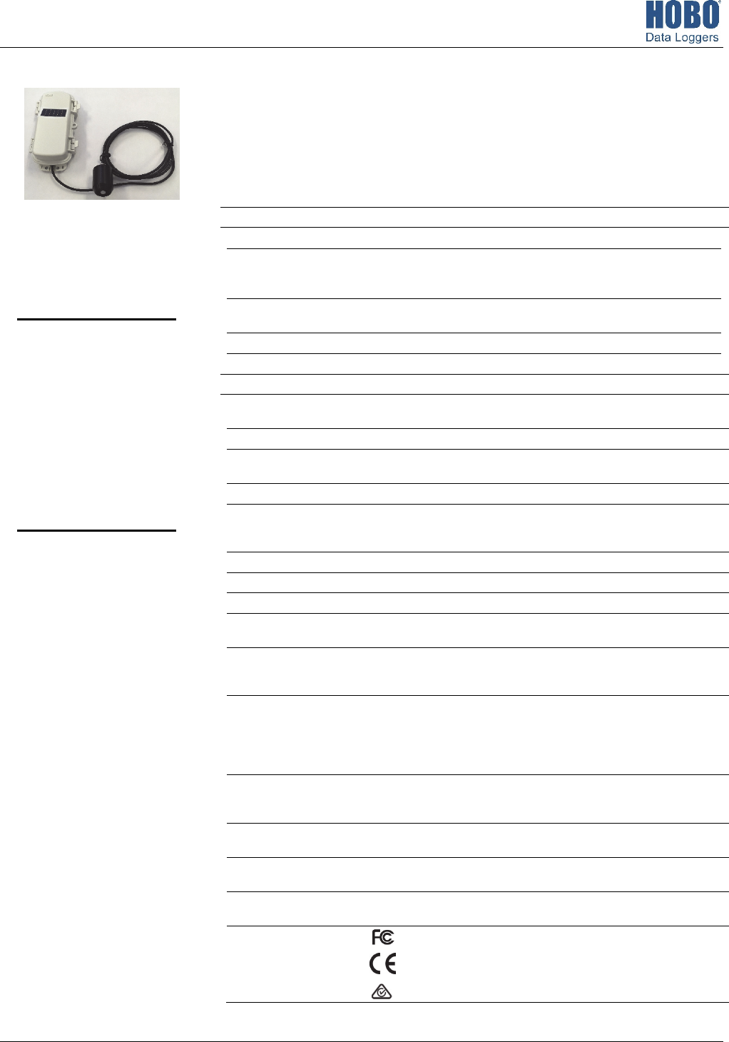
RXW PAR Sensor (RXW-LIA-xxx) Manual
22246-2
This sensor measures photosynthetically active radiation (PAR) and is designed to work with the
HOBO RX Wireless Sensor Network in which data is transmitted wirelessly from the sensor mote
across the network to the RX3000 station and then uploaded to HOBOlink® web-based software.
With HOBOlink, you can monitor sensor readings, view graphs, set up alarms, download data, and
more.
Specifications
Sensor
Measurement Range 0 to 2500 μmol/m
2
/sec, wavelengths 400 to 700 nm (see Plot A)
Accuracy ±5 μmol/m
2
/sec or ± 5%, whichever is greater in sunlight; Additional
temperature induced error ±0.75 μmol/m
2
/sec/°C from 25°C
(0.42 μmol/m
2
/sec/°F from 77°F)
Angular Accuracy Cosine corrected 0 to 80 degrees from vertical; Azimuth Error <2% error
at 45 degrees from vertical, 360 degree rotation
Resolution 2.5 μmol/m
2
/sec
Drift <±2% per year
W
ireless Mote
O
perating Temperature
Range
-25° to 60°C (-13° to 140°F) with rechargeable batteries
-40 to 70°C (-40 to 158°F) with lithium batteries
Radio Power 12.6 mW (+11 dBm) non-adjustable
Transmission Range At least 304.8 m (1,000 ft) line of sight at 1.8 m (6 ft) from the ground,
457.2 m (1,500 ft) typical
Wireless Data Standard IEEE 802.15.4
Radio Operating
Frequencies
RXW-LIA-900: 904–924 MHz
RXW-LIA-868: 866.5 MHz
RXW-LIA-922: 916–924 MHz
Modulation Employed OQPSK (Offset Quadrature Phase Shift Keying)
Data Rate Up to 250 kbps, non-adjustable
Duty Cycle <1%
Maximum Number of
Motes
50 motes per one RX Wireless Sensor Network
Battery Type/
Power Source
Two AA 1.2V rechargeable NiMH batteries, powered by built-in solar panel
or two AA 1.5 V lithium batteries for operating conditions of -40 to 70°C (-40
to 158°F)
Battery Life With NiMH batteries: Typical 3–5 years when operated in the temperature
range -20° to 40°C (-4°F to 104°F) and positioned toward the sun (see
Deployment and Mounting), operation outside this range will reduce the
battery service life
With lithium batteries: 1 year, typical use
Dimensions Sensor: 4.1 cm height x 3.2 cm diameter (1.61 x 1.26 inches)
Cable length: 2 m (6.56 ft)
Mote: 16.2 x 8.59 x 4.14 cm (6.38 x 3.38 x 1.63 inches)
Weight Sensor and cable: 109 g (3.85 oz)
Mote: 223 g (7.87 oz)
Materials Sensor: Anodized aluminum housing with acrylic diffuser and O-ring seal
Mote: PCPBT, silicone rubber seal
Environmental Rating Sensor and cable: Weatherproof
Mote: IP67
C
ompliance Marks RXW-LIA-900: See last page
RXW-LIA-868: The CE Marking identifies this product as complying
with all relevant directives in the European Union (EU).
RXW-LIA-922: See last page
RXW PAR Sensor
Models:
• RXW-LIA-900 (US)
• RXW-LIA-868 (Europe)
• RXW-LIA-922 (Australia/NZ)
Items Included:
• Cable ties
Accessories:
• Light sensor mounting
bracket (M-LBB)
• Light sensor level (M-LLA)
RXW LIA Sensor (RXW-LIA-xxx) Manual
1-800-LOGGERS 2 www.onsetcomp.com
Mote Components and Operation
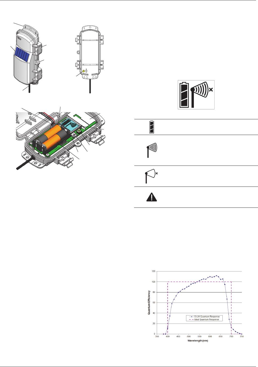
Sensor Mote Closed, Front Sensor Mote Closed, Back
Sensor Mote Opened
Mounting Tab: Use the tabs at the top and bottom of the mote
to mount it (see Deploying and Mounting).
Solar Panel: Position the solar panel towards the sun to charge
the mote batteries (see Deploying and Mounting).
Sensor Cable: This is the cable that connects the mote to the
sensor.
Eyelet: Use this eyelet to attach a 3/16 inch padlock to the
mote for security.
Latch: Use the two latches to open and close the mote door.
Ground Wire Port: Use this port to connect a ground wire (see
Deploying and Mounting).
Antenna: This is the built-in antenna for the radio
communications across the RX Wireless Sensor Network.
Solar Panel Cable: This cable connects the built-in solar panel
to the mote circuitry.
LEDs: The blue LED to the left of the LCD screen blinks at 4
seconds during normal operation. It blinks more frequently
when initially joining a network. If the mote is not currently
part of a network, the blue LED will be off. If the LED is on and
not blinking, there is a problem with the mote. Contact
Technical Support at www.onsetcomp.com/support/contact.
The yellow-green LED to the upper right of the batteries only
blinks during the process of joining a network.
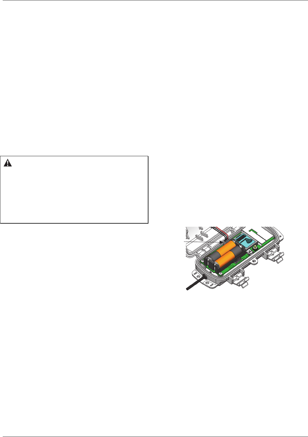
Battery Holder: The location where the rechargeable AA
batteries are installed as shown (see Battery Information).
USB Port: Use this port to connect to the mote to a computer
via USB cable if you need to update the firmware (see Updating
Mote Firmware).
Button: Push this button for 1 second to illuminate the LCD or 3
seconds for the mote to search for an RX Wireless Sensor
Network to join (see Adding the Mote to the RX Wireless Sensor
Network).
LCD Screen: The mote is equipped with an LCD screen that
displays details about the current status. This example shows all
symbols illuminated on the LCD screen followed by definitions
of each symbol in the table.
LCD Symbol Description
The battery indicator shows the approximate
battery charge remaining.
This is a signal strength indicator. The more bars,
the stronger the signal between motes. This icon
will blink when you press the button on the mote
to search for a network to join (see Adding the
Mote to the RX Wireless Sensor Network for
details).
This indicates that the mote is not part of a
network. See Adding the Mote to the RX Wireless
Sensor Network for details on how to add a mote
to the network.
This indicates a problem with the sensor itself (the
mote is operational). Check the sensor and make
any adjustments to it as needed. Contact Onset
Technical Support if the problem persists.
Typical Quantum Response
The PAR sensor is designed to detect photons between 400–
700 nm in wavelength. Ideally the sensor would count photons
with equal efficiency between 400–700 nm and no photons
would be counted outside this range. However, in reality, this
sensor undercounts photons between 400–550 nm and
between 670–700 nm, and it overcounts photons between
550–670 nm. In most applications (where the sensor is used in
natural sunlight) the error is not significant.
Plot A: PAR Sensor Typical Quantum Response
Solar Panel Latch
Button
Mounting
Tab
USB Port
Battery Holder
LCD Screen
Solar Panel Cable
Antenna
LED
Eyelet
LED
Ground Wire
Port
Sensor Cable
RXW LIA Sensor (RXW-LIA-xxx) Manual
1-800-LOGGERS 3 www.onsetcomp.com
Adding the Mote to the RX Wireless Sensor
Network
The mote must join an RX Wireless Sensor Network before it
can begin measuring PAR and transmitting data. This requires
accessing the RX3000 Station and the mote at the same time so
it is recommended that you complete these steps before
deploying the mote.
Important: If you have not configured the RX3000 Station with
the RXW Manager, follow the instructions in the RX3000 Quick
Start before continuing.
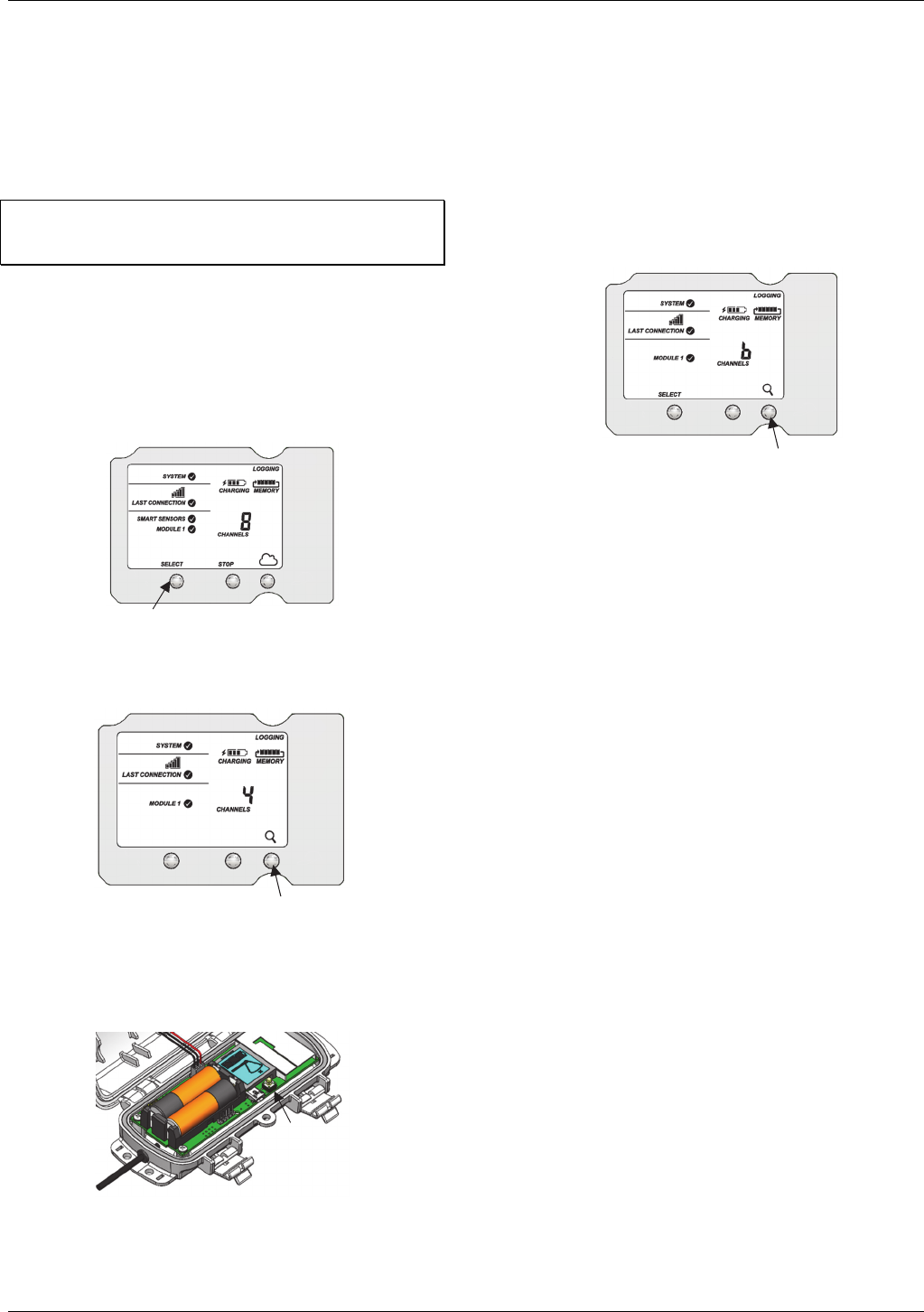
To add a mote to the RX Wireless Sensor Network:
1. If the LCD is blank on the RX3000 station, press any button
to wake it up.
2. Press the Select button once (which shows the number of
smart sensors installed) and then press it again once if the
HOBO RXW Manager is installed in the left slot (module 1)
or twice if it is installed on the right slot (module 2).
3. Press the Search button (the magnifying glass). The
magnifying glass icon will blink while the RX3000 is in search
mode.
4. Open the mote door and install the batteries if you have not
already done so.
5. Press the button on the mote for 3 seconds. The signal
strength icon will flash and then cycle.
6. Watch the LCD on the mote. The signal strength icon and
the LEDs will quickly blink while the mote searches for the
wireless network. Once it has found the network, the icon
will stop blinking and the signal strength bars will slowly
cycle from left to right. As the mote completes its
registration process with the network, the “x” icon to the
right of the signal strength icon will flash and the yellow-
green LED will stop blinking. Once the registration is
complete, the signal strength bars will stop cycling and
remain solid and the channel count on the RX3000 LCD will
be updated. This process may take up to five minutes. Note:
The channel count on the LCD will increase by 2: one for
PAR and one for the mote battery.
7. Press the Search button (the magnifying glass) on the
RX3000 Station to stop searching for motes.
Measurements will be recorded at the logging interval specified
in HOBOlink, transmitted to the RX3000 Station, and uploaded
to HOBOlink at the next connection interval (readout). Use
HOBOlink to monitor mote status and health. If a mote is
temporarily offline, any logged data is saved until it is back
online. In addition, if a mote is offline for 30 minutes, the
RX3000 Station will automatically connect to HOBOlink and
report the mote as missing. Once the mote is back online, any
logged data will be uploaded the next time the RX3000 station
connects to HOBOlink.
See the HOBOlink Help for details on how to change the logging
and connection intervals, view data, check mote status, add the
mote to a map, and more.
Deployment and Mounting
Mounting and Positioning the Mote
• Use cable ties to mount the mote via the holes on the
mounting tabs.
• Avoid mounting the mote near metal, which can cause
interference with the signal.
• Position the mote towards the sun, making sure the solar
panel is oriented so that it receives optimal sunlight
throughout each season. It may be necessary to periodically
adjust the mote position as the path of the sunlight changes
throughout the year or if tree and leaf growth alters the
amount of sunlight reaching the solar panel.
• Make sure the mote door is closed, with both latches fully
locked to ensure a watertight seal.
• Consider using a 3/16 inch padlock to restrict access to the
mote. With the mote door closed, hook a padlock through
the eyelet on the right side of the door and lock it.
• To maximize the communication between motes, place
the mote within 304.8–457.2 m (1,000–1,500 feet) and full
line of sight with the next mote in the network and at least
1.8 m (6 feet) from the ground.
Press this button to view the module
where the RXW Manager is installed
Press this button so the station is ready
to have motes join the network
Press this button for 3
seconds for the mote to
join the network
Press this button again to
stop searching for motes
RXW LIA Sensor (RXW-LIA-xxx) Manual
1-800-LOGGERS 4 www.onsetcomp.com
• If there is an obstruction between two sensor motes or
between the sensor mote and the RXW Manager, then use
an RXW Repeater (RXW-RPTR-xxx) mounted higher than
the two motes. For example, if there is a hill or mountain
between the sensor mote and the RXW Manager, place a
repeater at the top of the hill between the sensor mote
and the RXW Manager.
• There should not be more than five motes in any direction
from a repeater or the RXW Manager. Data logged by a
wireless sensor must travel or “hop” across the wireless
network from one mote to the next until it ultimately
reaches the RXW Manager at the RX3000 station. To make
sure the data can successfully travel across the network,
the sensor mote should not be more than five hops away
from a repeater or manager.
• The RX Wireless Sensor Network can support a maximum
of 50 motes.
• Use a #4-40 screw to attach a ground wire to the port on
the back of the mote if you are deploying the mote in a
location where lightning is a concern.
• Make sure the mote remains in a vertical position once it is
placed in its deployment location for optimal network
communications.
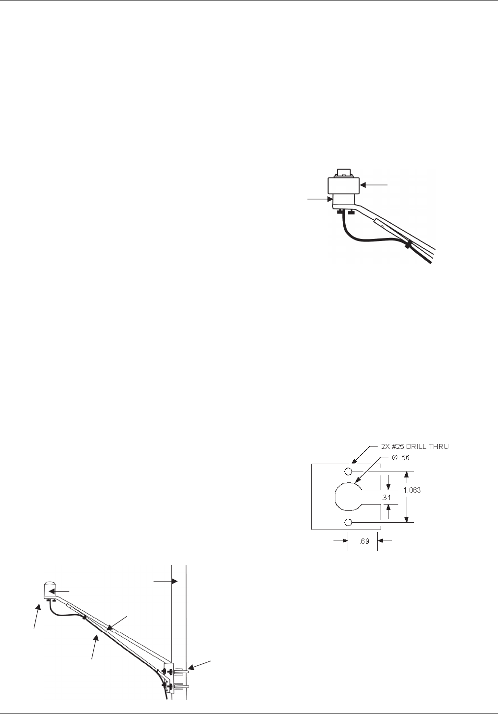
Mounting the Sensor with a Bracket
It is recommended that you mount the PAR sensor with the
light sensor mounting bracket (M-LBB) on a pole or tripod. Use
the light sensor level (M-LLA) to make sure it is level on the
bracket. To mount the PAR sensor using the bracket:
1. Attach the light sensor bracket to a 1¼ inch - 15/8 inch pole
with the provided U-bolts. Note: The bracket can also be
mounted on a flat, vertical surface using four screws.
2. Position the PAR sensor on top of the light sensor bracket
with its cable running through the slot in the bracket.
3. Using the two screws supplied, attach the sensor to the
bracket through the two holes on either side of the slot.
Note: Do not completely tighten the screws until you level
the PAR sensor.
4. Position the bracket so it faces toward the equator,
minimizing the chance of shading.
5. Mount the light sensor bracket on the mast with the two U-
bolt assemblies, mounting it high enough on the mast to
avoid the possibility of shading the PAR sensor. Note: If you
mount the PAR sensor above eye level, it is recommended
that you use a step ladder or other secure platform when
leveling the sensor so that you can clearly view the light
sensor level (M-LLA).
6. Make sure the screws holding the sensor to the mounting
bracket are loose.
7. Place the light sensor level on the PAR sensor.
8. Adjust the height of the thumbscrews to level the sensor
(start with the thumbscrews protruding about 1/16 inch
from the bracket).
9. Once the sensor is near level, tighten the Phillips head
screws.
10. Check the light sensor level and repeat above steps if
necessary.
11. When the sensor is level, remove the light sensor level from
the sensor.
Leveling the PAR Sensor on the Light Sensor Bracket
Mounting the Sensor on a Mounting Plate
To mount the light sensor using a mounting plate of your own
design:
1. Drill a 0.56 (9/16) inch hole in the middle of the plate, then
drill two #25 holes 1.063 (1-1/16) inches apart on either
side of the center hole. Cut a 0.31 (5/16) inch-wide slot in
the mounting plate as shown below. The plate should be a
thickness of 1/8 inch or less.
2. Slide the sensor through the 0.31 (5/16) inch-wide slot.
3. Attach the sensor using two 6-32 x 3/8 inch screws and lock
washers (not included).
4. Shim the sensor as necessary to level it
Recommended Mounting Plate Dimensions
Sensor Mounting Guidelines
• Small errors in alignment can produce significant errors.
Be certain that the sensor is mounted level.
• Mount the PAR sensor where it will not be in a shadow.
Any obstruction should be below the plane of the sensor
head. If that is not possible, try to limit obstructions to
below 5 degrees, where the effect will be minimal.
PAR sensor
Thumbscrew
PAR sensor cable
Mast
Light sensor
bracket
U-bolt assembly
PAR Sensor Bracket Mounting
Light sensor level
PAR sensor
RXW LIA Sensor (RXW-LIA-xxx) Manual
1-800-LOGGERS 5 www.onsetcomp.com
• If possible, avoid locating the sensor in dusty locations.
Dust, pollen, and salt residue that collect on the top of the
sensor can significantly degrade accuracy.
• Refer to the station manual and Tripod Setup Guide at
www.onsetcomp.com/support/manuals for more
information regarding setting up stations.
Sensor Operation
The PAR sensor averages measurements at a fixed rate of once
a minute. The multiple samples are then averaged together and
the average value is recorded at the logging interval. For
example, when the logging interval is set at 10 minutes, each
recorded data point will be the average of 10 measurements (1
sample per minute for 10 minutes).
Maintenance
Dust on the sensor will degrade sensor accuracy. Periodically
inspect the sensor, and if necessary, gently clean the diffuser
with a damp sponge. Do not open the sensor as there are no
user serviceable parts inside.
Warning: DO NOT use alcohol, organic solvents, abrasives,
or strong detergents to clean the diffuser element on the PAR
sensor. The acrylic material used in the PAR sensor can be
crazed by exposure to alcohol or organic solvents. Clean the
sensor only with water and/or a mild detergent such as
dishwashing soap if necessary. It is recommended that you use
vinegar to remove hard water deposits from the diffuser
element. Under no circumstances should the sensor be
immersed in any liquid.
The mote is designed for outdoor use, but should be inspected
periodically. When inspecting the mote, do the following:
• Verify the mote is free of visible damage or cracks.
• Make sure the mote is clean. Wipe off any dust or grime
with a damp cloth.
• Wipe off any water before opening the mote.
• Make sure the interior seal is intact and the latches are
fully locked when the mote door is closed.
Verifying Sensor Accuracy
It is recommended that you check the accuracy of the PAR
sensor annually. The PAR sensor cannot be calibrated. Onset
uses precision components to obtain accurate measurements.
If the sensor is not providing accurate data, then it may be
damaged.
Updating Mote Firmware
If a new firmware version is available for the mote, use
HOBOlink to download the file to your computer. Connect the
mote to the computer with a USB cable (open the mote door
and use the USB port to the right of the LCD). The mote appears
as a new storage device in the computer’s file storage manager.
Copy the downloaded firmware file to the new storage device
(the mote). After the file is copied, eject the storage device
from the computer and disconnect the cable from the mote.
The file will be installed automatically on the mote. Note to
Mac® users: A message may appear indicating the disk has not
ejected properly. The mote is operational and you can ignore
the message.
Battery Information
The mote uses two 1.2 V rechargeable NiMH batteries, charged
by the built-in solar panel. The quality and quantity of solar
light can affect whether the battery is sufficiently charged to
last through the night and cloudy periods. Make sure the mote
is placed in a location that will receive several hours of sunlight
each day. If the mote does not receive enough sunlight to
recharge the batteries, the battery life is estimated at 3–4
months. When batteries are regularly recharged, expected
battery life is estimated at 3–5 years. Battery life varies based
on the ambient temperature where the mote is deployed, the
logging interval, the number of tripped alarms, and other
factors. Deployments in extremely cold or hot temperatures
can impact battery life. Estimates are not guaranteed due to
uncertainties in initial battery conditions and operating
environment.
Mote operation will stop when battery voltage drops to 1.8 V.
Mote operation will return if the battery recharges to 2.3 V. If
the batteries are unable to be recharged, replace them with
fresh rechargeable batteries.
To replace rechargeable batteries:
1. Open the mote door.
2. Remove the old batteries and install the new ones
observing polarity.
3. Make sure the solar panel cable is plugged in.
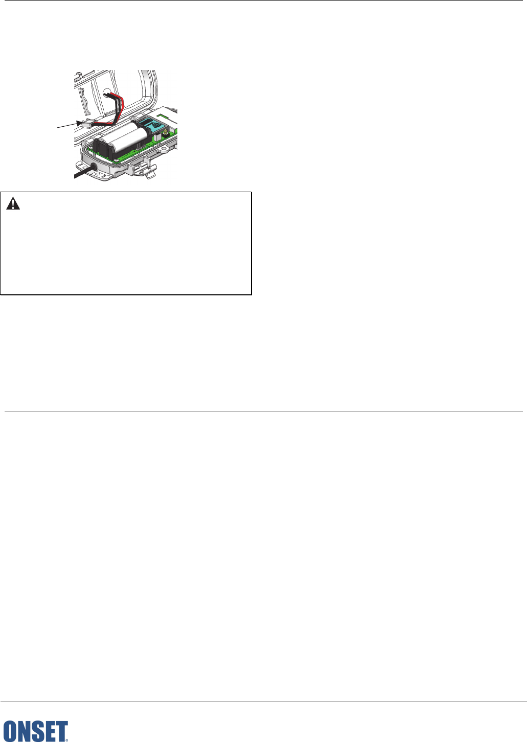
You can use two 1.5 V lithium batteries (HWSB-LI) for operation
at the extreme ends of the mote operating range. Lithium
battery life is an estimated at 1 year, but varies based on the
ambient temperature where the mote is deployed, the logging
interval, the number of tripped alarms, and other factors.
Estimates are not guaranteed due to uncertainties in initial
battery conditions and operating environment. When using
lithium batteries, you must disconnect the solar panel cable
because the batteries will not be recharged.
To install lithium batteries:
1. Open the mote door.
2. Remove any old batteries and install the new ones
observing polarity.
3. Push in the side tab of the solar panel cable connector and
pull the connector out of the cable port.
Make sure
solar panel
cable is
installed
when using
rechargeable
batteries
RXW LIA Sensor (RXW-LIA-xxx) Manual
1-800-LOGGERS (564-4377) • 508-759-9500
www.onsetcomp.com/support/contact
© 2018 Onset Computer Corporation. All rights reserved. Onset, HOBO, and HOBOlink are registered
trademarks of Onset Computer Corporation. Mac is a registered trademark of Apple Inc. All other trademarks
are the property of their respective companies.
22246-2
4. Place the connector in the slot on the inside of the mote
door. Make sure the solar panel cables are tucked inside the
door so that they do not interfere with the interior seal
when the mote is closed.
WARNING: Do not cut open, incinerate, heat above 85°C
(185°F), or recharge the batteries. The batteries may explode if
the logger is exposed to extreme heat or conditions that could
damage or destroy the battery cases. Do not mix battery types,
either by chemistry or age; batteries may rupture or explode.
Do not dispose of the logger or batteries in fire. Do not expose
the contents of the batteries to water. Dispose of the batteries
according to local regulations.
Federal Communication Commission Interference Statement
This equipment has been tested and found to comply with the limits for a Class B digital device, pursuant to Part 15 of the FCC Rules. These limits are designed to provide
reasonable protection against harmful interference in a residential installation. This equipment generates uses and can radiate radio frequency energy and, if not installed and
used in accordance with the instructions, may cause harmful interference to radio communications. However, there is no guarantee that interference will not occur in a
particular installation. If this equipment does cause harmful interference to radio or television reception, which can be determined by turning the equipment off and on, the user
is encouraged to try to correct the interference by one of the following measures:
• Reorient or relocate the receiving antenna
• Increase the separation between the equipment and receiver
• Connect the equipment into an outlet on a circuit different from that to which the receiver is connected
• Consult the dealer or an experienced radio/TV technician for help
This device complies with Part 15 of the FCC Rules. Operation is subject to the following two conditions: (1) This device may not cause harmful interference, and (2) this device
must accept any interference received, including interference that may cause undesired operation.
FCC Caution: Any changes or modifications not expressly approved by the party responsible for compliance could void the user's authority to operate this equipment.
Industry Canada Statements
This device complies with Industry Canada license-exempt RSS standard(s). Operation is subject to the following two conditions: (1) this device may not cause interference, and
(2) this device must accept any interference, including interference that may cause undesired operation of the device.
Avis de conformité pour l’Industrie Canada
Le présent appareil est conforme aux CNR d'Industrie Canada applicables aux appareils radio exempts de licence. L'exploitation est autorisée aux deux conditions suivantes : (1)
l'appareil ne doit pas produire de brouillage, et (2) l'appareil doit accepter tout brouillage radioélectrique subi, même si le brouillage est susceptible d'en compromettre le
fonctionnement.
To comply with FCC and Industry Canada RF radiation exposure limits for general population, the logger must be installed to provide a separation distance of at least 20cm from
all persons and must not be co-located or operating in conjunction with any other antenna or transmitter.
Store the solar
panel connector
here when using
lithium batteries