Opticon Sensors Europe PX36 Barcode data collector User Manual
Opticon Sensors Europe BV Barcode data collector
UserManual.wiki
>
Opticon Sensors Europe
>
PX36 User Manual
>
User Manual
Contents
1.
User Manual
2.
Manual of Cradle
User Manual
Navigation menu
Upload a User Manual
Namespaces
Wiki Guide
HTML
PDF
Info
Views
User Manual
Discussion / Help
Navigation

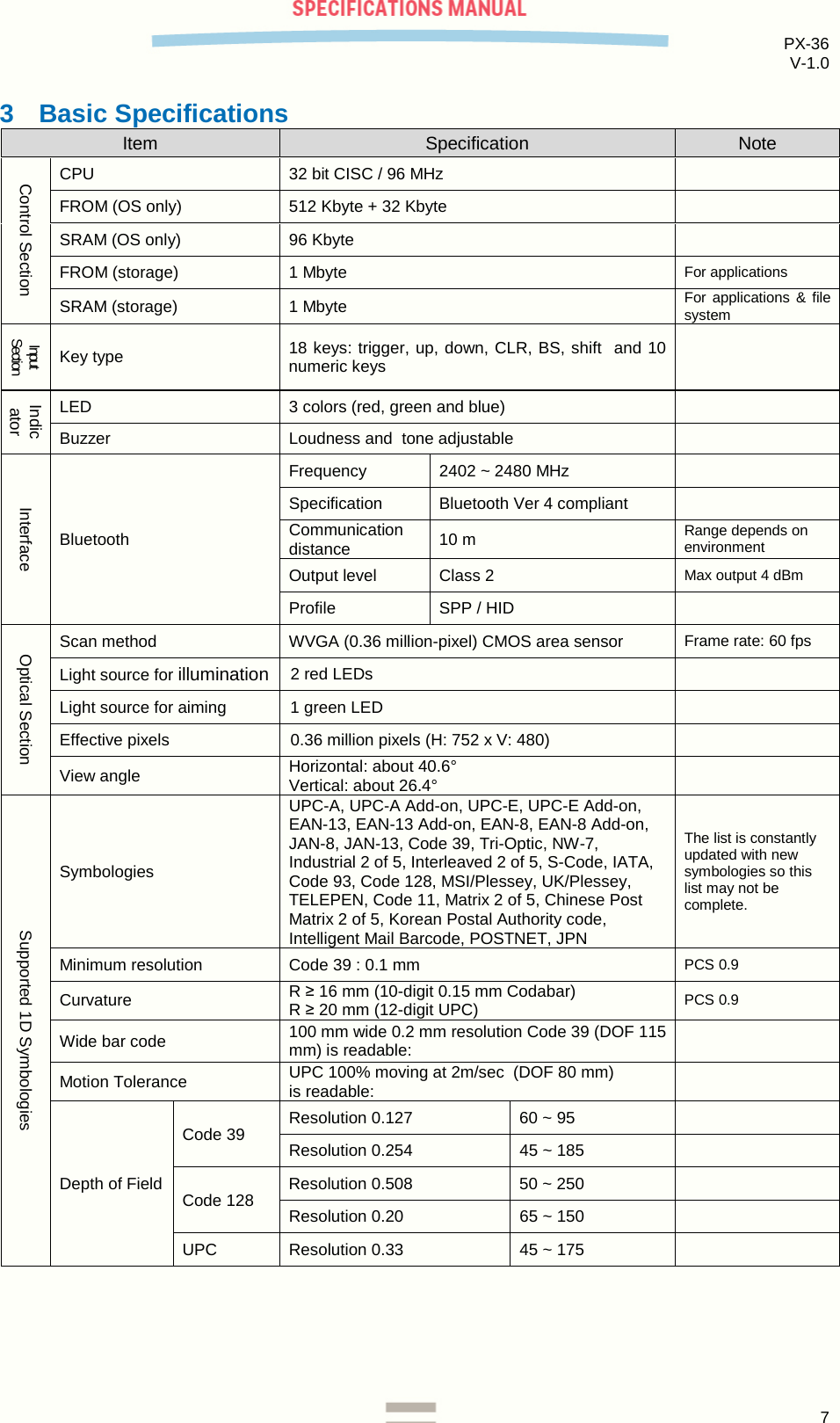
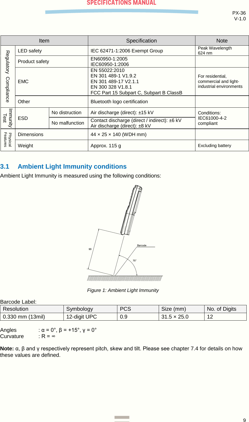

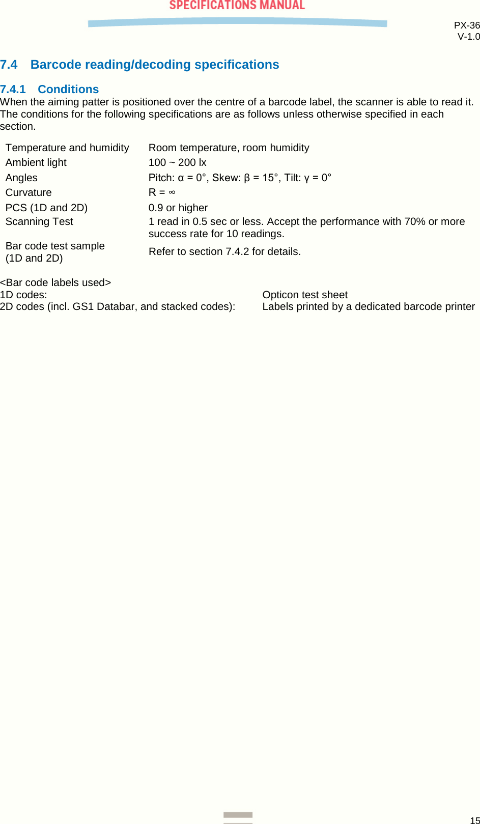
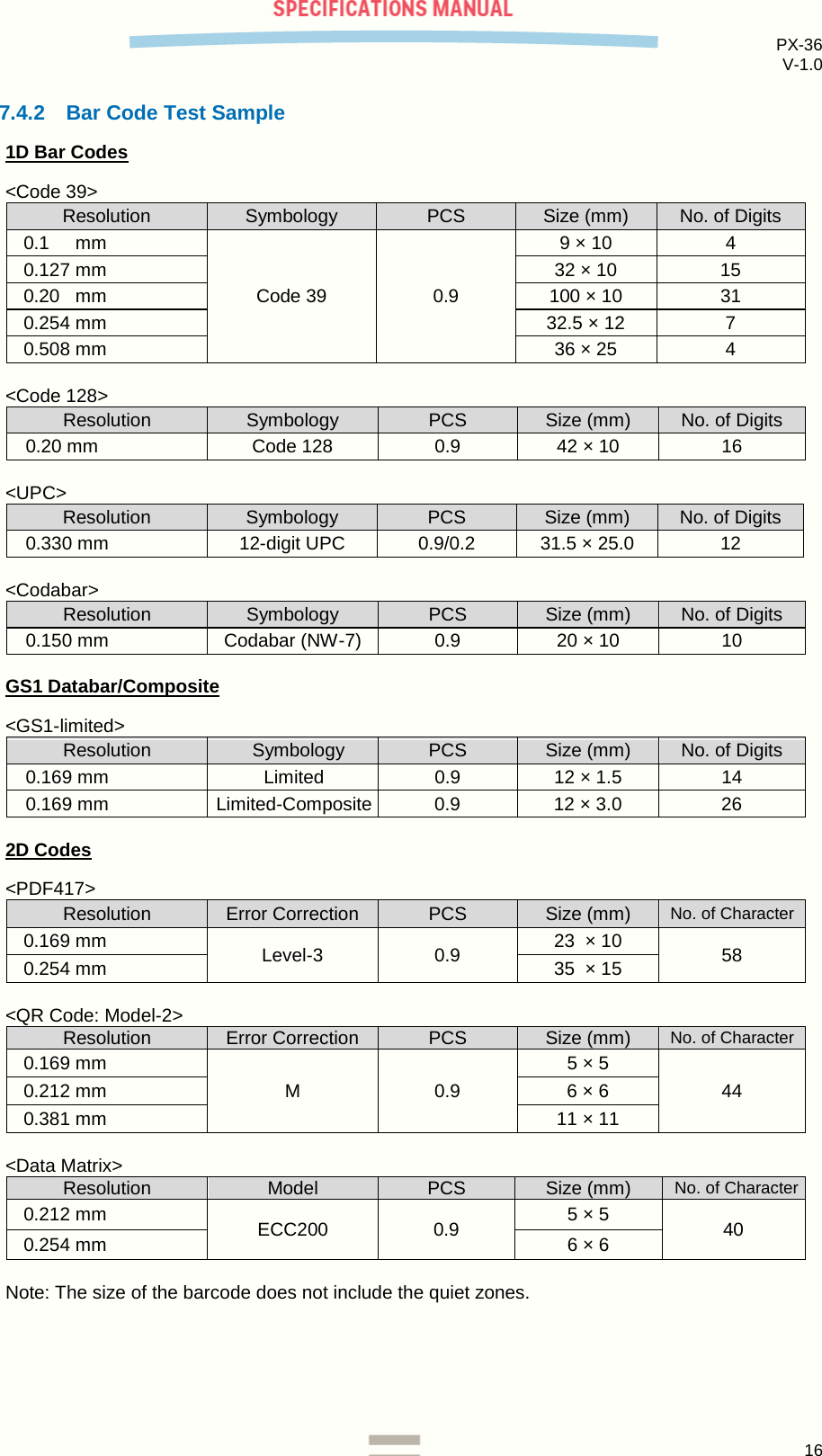
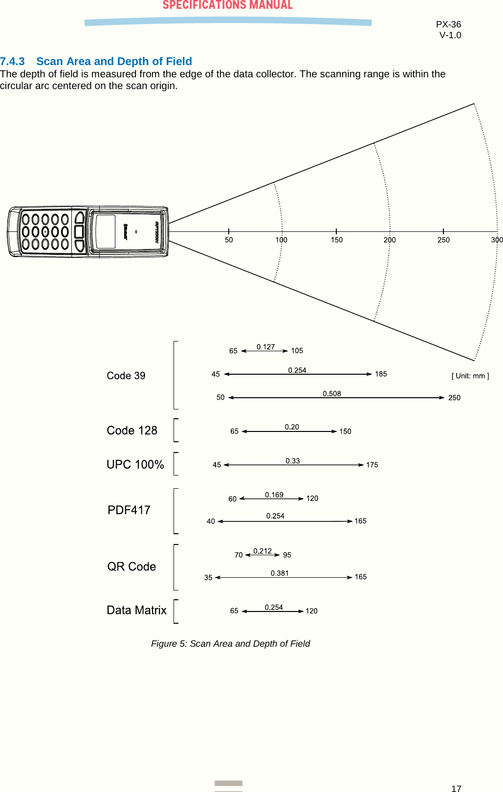
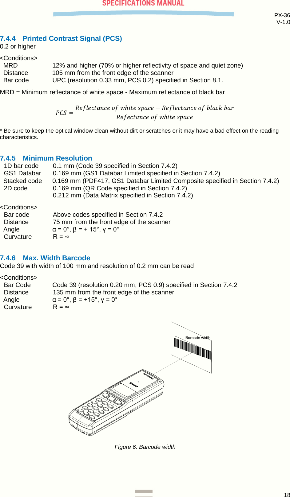
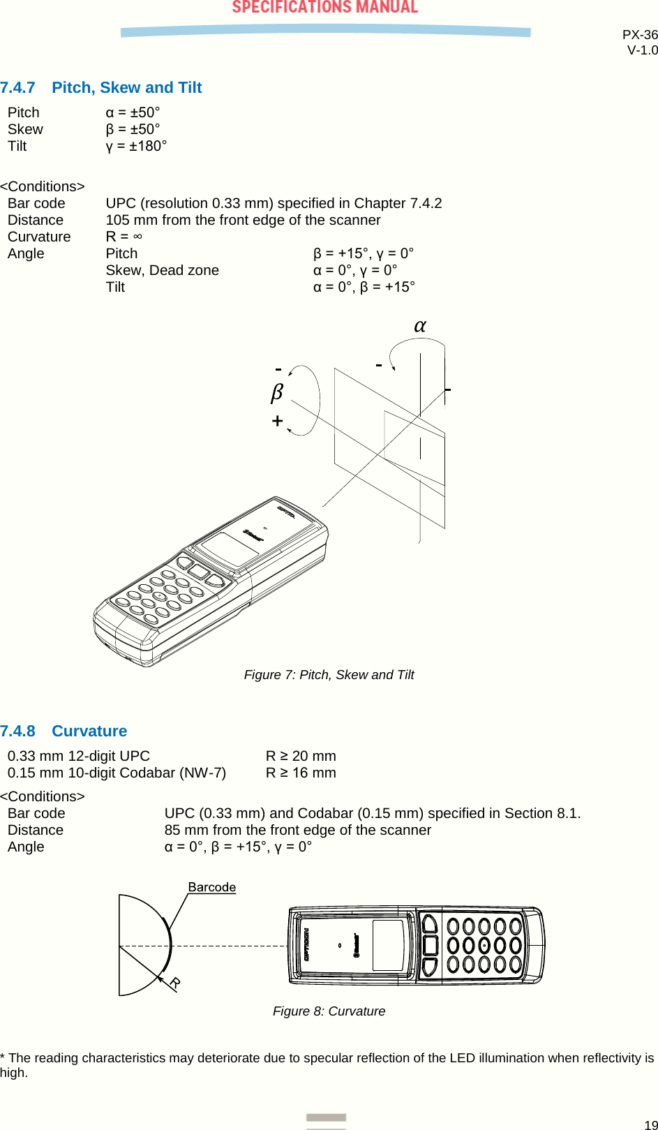
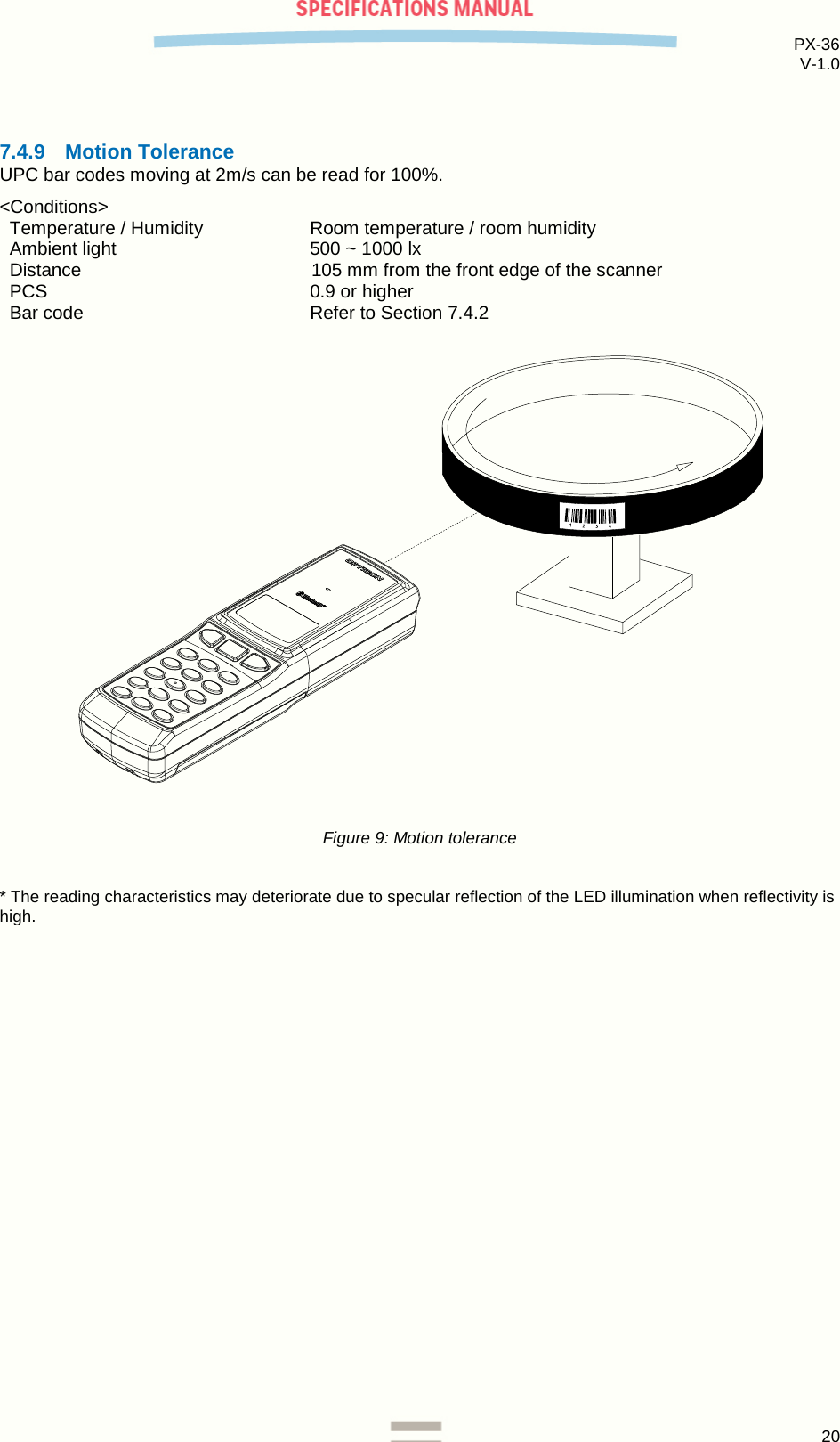
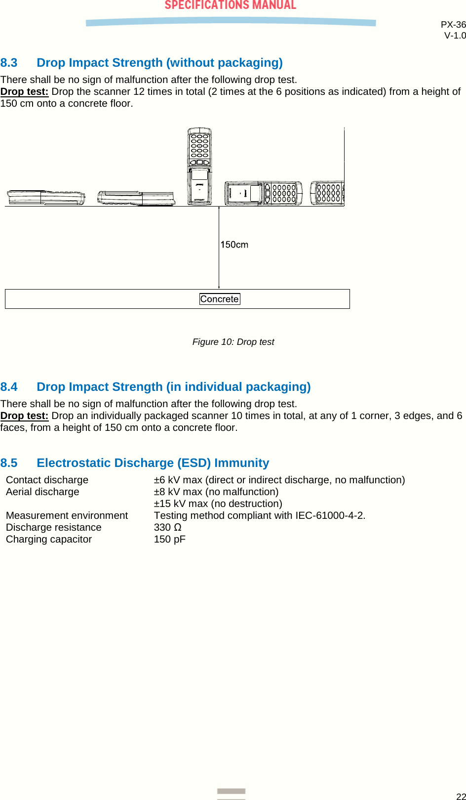
![PX-36 V-1.0 14 7.2 Aiming Pattern The aiming pattern is used for the following purposes: 1. Light source to indicate the appropriate reading range. 2. Light source for auto trigger operation. The specifications for the aiming pattern are as follows: ・ The optical axis of the field of view and the center of the aiming pattern coincide at a distance of L=65±20 mm from the front edge of the scanner. ・ The width of the aiming pattern is 80%±10% of the width of the field of view at a distance of L=65mm. Figure 4: Aiming pattern 7.3 Imaging Range L: Distance from the front edge of scanner [mm] 40 60 80 100 120 140 H: Horizontal imaging range [mm] 66 82 97 111 125 136 V: Vertical imaging range [mm] 42 52 62 72 82 93 All values have an accuracy of ±5%.](https://usermanual.wiki/Opticon-Sensors-Europe/PX36.User-Manual/User-Guide-2931603-Page-14.png)