Opticon DD6000controller DD6000
User Manual: Opticon
Open the PDF directly: View PDF ![]() .
.
Page Count: 98

User's manual DD6000 controller
controller for the OSENET network

Copyright © 1993, Opticon Sensors Europe B.V. All Rights Reserved
This manual may not, in whole or in part, be copied, photocopied, reproduced, trans-
lated or converted to any electronic medium or machine readable form without prior
written consent of Opticon Sensors Europe.
Limited warranty and disclaimers
By opening the package of this network controller you agree to become bound by the
liability and warranty conditions as described below.
Under all circumstances this manual should be read attentively, before installing and/or
using the product. In no event Opticon Sensors Europe will be liable for any direct, indi-
rect, consequential or incidental damages arising out of improper use of both the hard-
ware and software.
A serial number appears on all Opticon products. This official registration number is
strictly related to the device purchased. Please ensure that the serial number appear-
ing on your Opticon device has not been removed. Servicing by Opticon's Technical
Department can be only carried out under warranty if this number appears on the
device.
All Opticon products are warranted for a period of one year after purchase, covering
defects in material and workmanship. Opticon will repair or, at its discretion, replace
products that prove to be defective in material or workmanship under proper use during
the warranty period.
Opticon will not be liable in case the product is opened by unauthorised parties. In
such case the standard repair charge will be applicable. The standard charge for repair
will also be applicable in case no defect is found at all. These conditions also apply for
products that are still under warranty. Therefore, you are advised to always have the
product's specifications at hand.

CONTENTS
INTRODUCTION ............................................................................ i
LIST OF ABBREVIATIONS ...................................................... iii
1. THE DD6000 NETWORK CONTROLLER .............................1
1.1 Mechanical features ........................................................................4
1.2 Technical specifications ...............................................................6
2. OSENET NETWORK EQUIPMENT ....................................... 9
2.1 Controller and decoders ............................................................11
2.2 Cable work ................................................................................12
2.3 Installation and setup ................................................................16
3. THE OSENET SYSTEM ....................................................... 19
3.1 The OSENET protocol ...............................................................21
3.2 Programming OSENET .............................................................26
4. CONTROLLER-HOST COMMUNICATION PROTOCOL .... 35
5. TIME ANALYSIS OF OSENET ............................................. 39
CONTENTS

CONTENTS
appendices
A. PIN ASSIGNMENT OF PORTS .......................................... 49
B. TABLE WITH READ DIRECT LABELS ............................... 55
C. LISTING RESPONSE TIME PROGRAM ............................ 69
D. GLOSSARY OF TERMS ..................................................... 79

The DD6000 network controller for OSENET allows multiple DD6000 decoders to be
connected to a single host computer. The controller transposes the data streams com-
ing from the decoders into a single data stream which can be accepted by the host
computer. Conversely, messages coming from the host and intended for a decoder
have to pass the controller. Both host-controller and controller-decoder communication
has to take place according to certain rules: the data link protocol. These protocols take
care of the integrity of the communication between the devices.
The controller is thus concerned with two separate data links: one which connects it
to the DD6000s, and one which connects it to the host. The first data link is described
in part 3. The latter data link is described in part 4. In order to better comprehend the
features of OSENET, it is recommended to read the manual "User's manual DD6000"
before reading this manual.
The OSENET system allows for high speed data transmission across both data links.
The default baud rate for decoder-controller communication is 125Kbps. The DD6000
network controller supports two standard hardware interfaces for controller-host com-
munication: RS232 and RS422/RS485. The latter is extremely useful for network appli-
cations because it is less sensible to noise.
Both data link protocols are user programmable via bar code menus. The adjustable
parameters are stored in a non-volatile memory, so they remain present even when the
device is switched off.
This manual contains the following parts:
1. THE DD6000 NETWORK CONTROLLER
The DD6000 network controller is an interface control device used to transpose data,
coming from a number of decoders, into a data stream suited for the host computer.
Mechanical features of the controller, shown in this part, are very similar to the features
of the DD6000 decoder. This part also describes technical specifications of both soft-
INTRODUCTION
INTRODUCTION i

ware and hardware of the controller.
2. OSENET NETWORK EQUIPMENT
OSENET is a full duplex, multidrop RS485 connection, allowing the connection of sev-
eral stations to a shared host device. Up to 126 decoder stations can be connected.
This section describes the installation and setup of the network. Guidelines, in case
non-standard cable work is used, are indicated here. Moreover, some features of both
controller-decoders and host-controller communication are shown.
3. THE OSENET SYSTEM
Data exchange across the network has to be managed according to certain rules; the
OSEnet protocol. In the first section of this part the protocol is analised. In part 5 the
information about the protocol will be used to calculate the response time of the net-
work. In the second section bar code menus are present, which allows you to program
some features of the network.
4. CONTROLLER-HOST COMMUNICATION PROTOCOL
This section describes the communication between the controller and the host.
5. TIME ANALYSIS OF OSENET
In this section formulas are derived to calculate the response time for your specific
network. Figures help you to get a good impression of the speed of the network. The
guidelines indicated at the end of the section should be followed if the response time
turns out to be too long.
APPENDICES
• Appendix A describes the pin configuration of the ports of the controller.
• Appendix B contains a table with read direct bar code labels.
• Appendix C features a listing of a BASIC program to calculate the response time
for your network.
• Appendix D is the trouble shoot section.
• Appendix E contains a glossary of terms in which technical terms are explained.
ii INTRODUCTION

A: Ampere (unit of Current)
AC: Alternating Current
ACK: Acknowledge (ASCII-symbol 06h)
ANSI: American National Standards Institute
ASCII: American Standard for Code Information Interchange
CISPR: French initials for the International Special Committee on
Radio Interference
CR: Carriage Return (ASCII-symbol 0Dh)
CTS: Clear to Send
D: Depth
DC: Direct Current
DCD: Data Carrier Detect
DCE: Data Communications Equipment
DLE: Data Link Escape (ASCII-symbol 10h)
DOS: Disk Operating System
DSR: Data Set Ready
DTE: Data Terminating Equipment
DTR: Data Terminal Ready
EMC: Electro Magnetic Compatibility
ENQ: Enquiry (ASCII-symbol 05h)
LIST OF ABBREVIATIONS iii
LIST OF ABBREVIATIONS

EOP: End of Poll
EOT: End of Transmission (ASCII-symbol 04h)
ESD: Electro Static Discharge
ETX: End of Text (ASCII-symbol 03h)
f: Frequency
FF: Form feed (ASCII-symbol 0Ch)
FS: File separator (ASCII-symbol 1Ch)
GS: Group separator (ASCII-symbol 1Dh)
ID: Identification
IEC: International Electrotechnical Commission
ISO: International Standards Organisation
L: Length
LCD: Liquid Crystal Display
LED: Light Emitting Diode
LF: Line Feed (ASCII-symbol 0Ah)
LRC: Longitudinal Redundancy Check
NAK: Not Acknowledged (ASCII-symbol 15h)
OSENET: Opticon Sensors Europe Network
OSI: Open Systems Interconnection
PC: Personal Computer
RAM: Random Access Memory
ROM: Read Only Memory
RI: Ring Indicator
RS: Recommended Standard
iv LIST OF ABBREVIATIONS

RS: Record separator (ASCII-symbol 1Eh)
RTS: Request to Send
RxD: Received Data
SOH: Start of Heading (ASCII-symbol 01h)
STX: Start of Text (ASCII-symbol 02h)
TTL: Transistor Transistor Logic
TxD: Transmitted Data
V: Volt (unit of potential)
W: Width
LIST OF ABBREVIATIONS v

vi

the DD6000 network controller
1

2
THE DD6000 NETWORK CONTROLLER 3
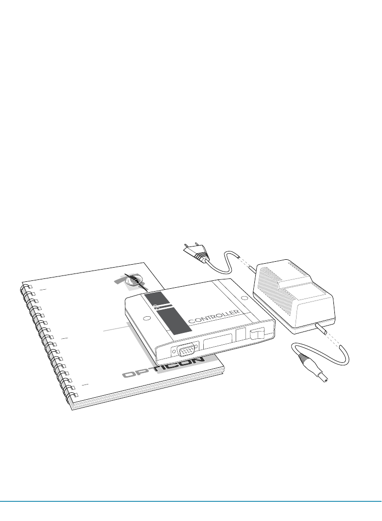
Remove the system components from their packing and inspect them for any evidence
of physical damage. If the shipping container shows external damage and the controller
does not operate properly, get in contact with the shipping firm for a claim.
Keep the packing: It should be used whenever the controller is transported for servic-
ing. Damage caused by improper repacking is not covered by the warranty. At any time
the following components should be present:
- this manual
- the DD6000 network controller
- 5 Volt DC power supply
For the network, Opticon can either deliver standard cabling resources or meet the
needs of the customer.
In this part mechanical features and technical specifications of the DD6000 control-
ler will be described. A description of how to install the network is given in part 2,
"OSENET network equipment".
User's manual
DD6000 controller
controller for the OSE network
Figure 1.1 Components present in packing of DD6000 network controller.
4 THE DD6000 NETWORK CONTROLLER
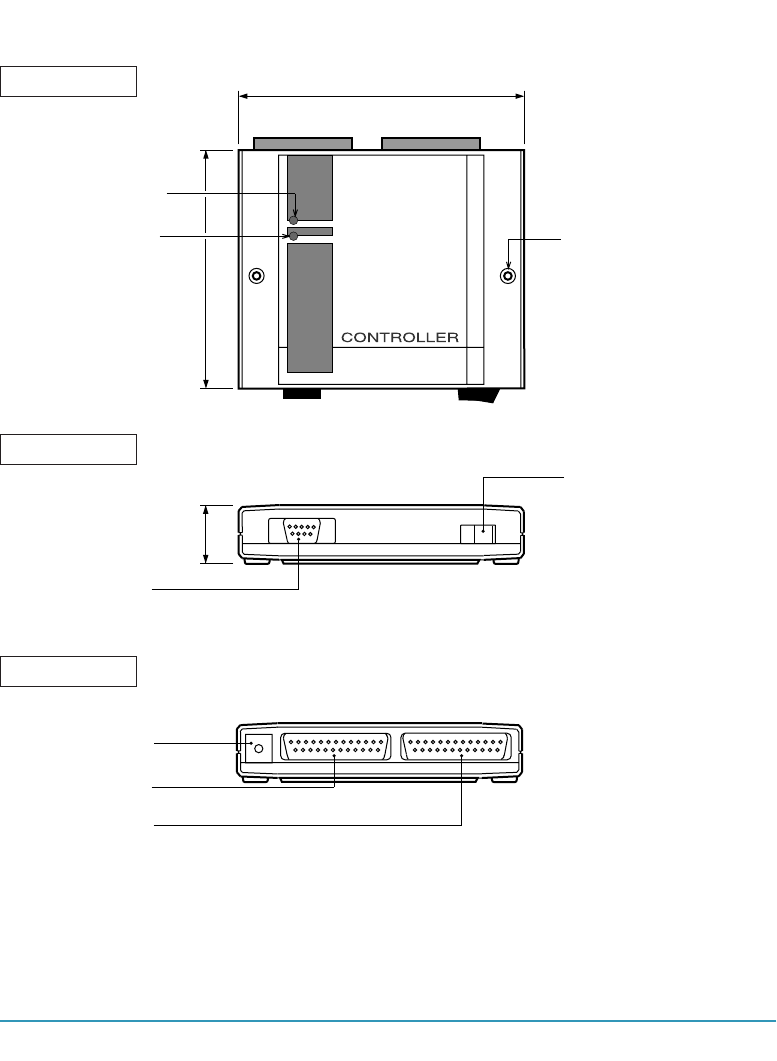
PORT I1
PORT O2
PORT O1
ON/OFF SWITCH
POWER
GOOD READ LED
POWER ON LED
117.0
140.7
MOUNTING HOLE
31.2
Figure 1.2 Top, front and rear view on the DD6000 network controller.
1.1 MECHANICAL FEATURES
REAR VIEW
FRONT VIEW
TOP VIEW
THE DD6000 NETWORK CONTROLLER 5
FEATURE DESCRIPTION
good read LED - Green LED indicates whether the data has been transmitted
correctly.
power on LED - Red LED indicates whether the power is on.
mounting hole - Allows solid mounting in any position.
port I1 - Port for connection of bar code scanning device such as
wand or CCD-scanner. With the scanner, bar code labels
can be read to set several parameters for OSENET and
configuration of the host-controller data link protocol.
port O1 - This port should be connected to the host-computer.
port O2 - This port is used for connection to the decoders via the
OSENET cabling.
power - 5 Volt DC power supply.
FRONT VIEW
TOP VIEW
REAR VIEW

6 THE DD6000 NETWORK CONTROLLER
1.2 TECHNICAL SPECIFICATIONS
HARDWARE AND ELECTRICAL FEATURES
Power supply voltage 5.0 V dc ± 5 %
Power supply current 150 mA without peripherals attached
Operating temperature -10o to 70o Celsius (IEC 68-2-1 and IEC 68-2-2)
Storage temperature -40o to 125o Celsius
Humidity 20%-95% non-condensing
Weight 270 g
Dimensions LxWxD: 127.0 x 140.7 x 31.2 mm
Vibration IEC 68-2-6 ( 5 Hz.<f<55 Hz, Axis 1G(X, Y, Z))
Shock IEC 68-2-27 (Pulse: half sine, T=18 ms, peak acc. 294 m/s2)
ESD IEC 801-2 ( up to 10 KV contact discharge)
EMC CISPR22 (radio interference) - class B
IEC 801-3 (radiated EM fields) - class 3
IEC 801-4 (electrical transient/burst) - class 3
Indicators 2 LEDs
1 Buzzer
Memory 256 bytes EEPROM, 32 Kbytes PROM, 130 Kbytes SRAM
Connectors -Port I1: 9 pins AMP squeeze-to-release male connector
-Port O1: DB25 female connector
-Port O2: DB25 male connector
Devices supported -Port I1: wand, CCD
-Port O1: host computer
-Port O2: DD6000 decoders (via OSENET)
Interfaces -Port I1: bar code reader
-Port O1: RS232, RS422/485
-Port O2: RS485 (OSENET)
The DD6000 network controller can be programmed by scanning bar code labels in the

THE DD6000 NETWORK CONTROLLER 7
programmer's guide, with a bar code reader connected to port I1.
PROGRAMMING FEATURES
host-controller communication features:
- baud rate
- handshake protocol
- communication protocol
- interface type
- parity
- number of stop bits
OSENET network features:
- baud rate
- decoder response time
- decoder recovery time
- maximum number of errors before off-line
- number of stations (decoders)
- separate station on/off-line
AND MORE !

8

OSENET network equipment
2

10
OSENET NETWORK EQUIPMENT 11
If a network of decoders is purchased, cable work is necessary to connect the DD6000
decoders to the network controller. Opticon can either deliver standard cable work or
meet the needs of the customer. Specifications and guidelines for the cable work are
given in section 2.2. Section 2.3 contains detailed instructions for installation of the
network. A network not meeting the guidelines and requirements indicated in this sec-
tion is not guaranteed to work properly. The last section shows you how to start-up the
equipment, once the network has been installed.
2.1 CONTROLLER AND DECODERS
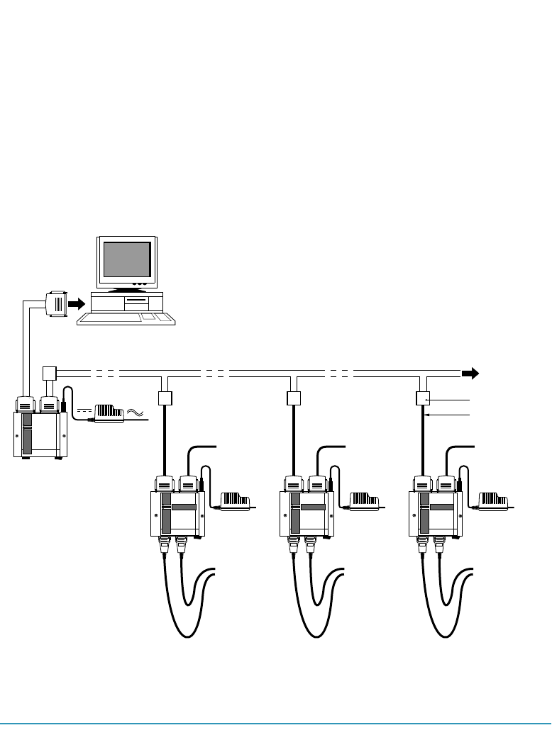
In a network configuration decoders and controller are positioned as in figure 2.1.
connect
to mains
5V DC
connection to
a serial port
controller
serial
device
scanning
device
serial
device
scanning
device
serial
device
scanning
device
HOST
connector-box
OSE-cable
CONTROLLER
AMP AMP
up to 126
decoders
AMP AMP AMP AMP
Figure 2.1 Configuration for a network of decoders.

12 THE OSENET NETWORK EQUIPMENT
Without repeaters 31 decoders can be connected to the controller. If more than 31 sta-
tions are connected to the controller, groups of stations are connected to the controller
in a tree-like structure, via repeaters. If a network of decoders (no. decoders <32) is
purchased, these are the components that should be present:
- DD6000 decoders
- DD6000 network controller
- cable work (section 2.2)
DD6000 decoders
With each decoder purchased, a power supply and a OSENET-cable are supplied in
addition.The OSENET-cable has a DB25 female connector and a 8p8 modular tele-
phone connector. The latter is used to connect port O1 of the decoder to the connector
box of the network.
DD6000 network controller
With each controller purchased, a power supply is supplied in addition.
2.2 CABLE WORK
The cable work physically connects the decoders to the controller, which on its turn
is connected to the host-computer. Many trade-offs in cable length and interfaces can
occur while designing the network. The maximum permitted cable length depends on
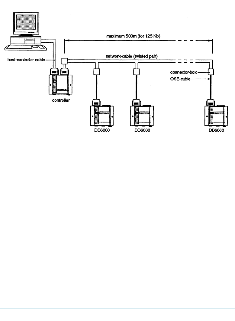
the interface and cable type used. Three sorts of cables are available:
• OSE-cable, to connect the decoder/controller to the belonging con-
nector box.
• Network cable, or main cable. This cable goes from the connector-
box belonging to the controller to the connector-boxes belonging to
the decoders.
• Host-controller cable. This cable connects the controller to the host
computer.
OSENET NETWORK EQUIPMENT 13
The OSE-cable
The OSE-cables are used to connect the DD6000 decoder to the connector boxes. You
are advised to keep these cables as short as possible. The maximal length of this cable
is approximately 2 meters. For longer cables you are advised to use shielded twisted
pair cables. A DB25 connector is used to connect the cable to the decoder. For con-
nection to the connector box an 8p8 modular telephone plug is used. Please refer to
appendix A for a detailed description of the connectors used.
The network cable or main cable
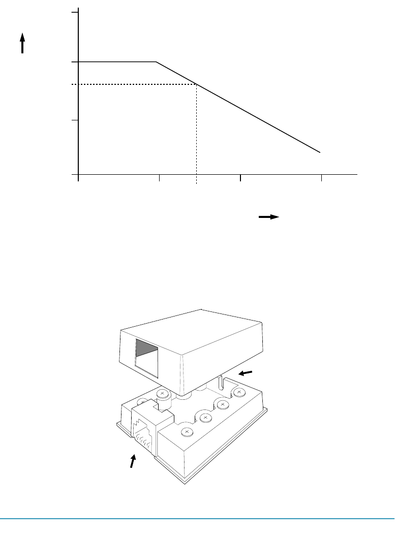
The maximal permissible length of network cable depends on the transmission speed
used. Increasing the cable length means increasing exposure to noise and signal dis-
tortion. Therefore, you are advised to restrict the cable length to a minimum. Figure 2.3
gives the data signalling rate versus the cable length for the RS422/485 interface, when
a twisted pair cable is used. The value of 500 meter, for a transmission speed of 125
kbps, should be considered to be a very conservative value. Larger cable lengths are
probably possible.
Figure 2.2 Cable-work for the OSENET network.
14 THE OSENET NETWORK EQUIPMENT
The network cable connects the controller to the decoder via the connector boxes.The
dimensions of the connector box, as shown in figure 2.4 are:
L x W x D: 55 x 49 x 20 mm.
Figure 2.3 Cable length as function of the signalling rate for the RS422/485 interface.
10 K 100 K 1 M 10 M
10
100
data signalling rate in bps
cable length in meters
1.2 K
500
125 K
10 K
connector for 8p8 modular
tele
p
hone connector
cut-away
for cable-work
Figure 2.4 Connector box.
OSENET NETWORK EQUIPMENT 15
At any time the connection should be as indicated in figure 2.5.
In this figure is:
pin 7 - GND - Logic ground
pin 9 - TR+ - Receive differential voltage
pin 10 - TR- - Receive differential voltage
pin 11 - T+ - Transmit differential voltage
pin 12 - T- - Transmit differential voltage
pin 15 - R. C. - Repeater control
The host-controller cable
The host-controller cable has two DB25 connectors to connect the controller to the
host computer. Two interfaces are available: RS232 and RS485. For short distances
between host and controller, the RS232 interface with a standard cable can be used.
For the relation cable length - data signalling rate for the RS232 interface, please refer
to table 2.1. In figure 2.4 this relation is given for the RS485 interface. You are advised
to use a twisted pair cable if the cable length is 2 meters or more.
7 9 10 11 12 15
DD6000 network
controller port O2
(DB25 female connector)
DD6000 decoder
port O1
(DB25 male connector)
DD6000 decoder
port O1
(DB25 male connector)
connection of pin 15 is optional, it can be used for repeater control
pin: pin:
other decoders
7 9 10 11 12 15 7 9 10 11 12 15
Figure 2.5 Pin connection for OSENET.

16 THE OSENET NETWORK EQUIPMENT
2.3 INSTALLATION AND SETUP
Once the decoders, controller and additional components have been unpacked, you
can start with the installation of the network. Before installing, locate the used decod-
ers, controller and belonging connector boxes, and determine the cabling needed with
in the back of your mind the guidelines for the cable work indicated in section 2.2.
To set up the network with standard cable-work, follow these steps:
1. Mount the connector-boxes at an appropriate place.
2. Mount the controller and decoders on a flat surface. The surface may be
vertical, horizontal, or any incline in between.
3. Lay the cabling. Connect the cores to the boxes in a way that the connec-
tions as shown in figure 2.5 are established.
4. Make sure that all electrical devices to be used are switched off.
Max. cable length
(meters)
<75
75
150
230
Baudrate
(bits per sec)
19200
9600
4800
2400
Table 2.1 The relation baud rate - maximum cable length for the RS232 interface.

OSENET NETWORK EQUIPMENT 17
5. Connect the DD6000 decoders with a OSENET-cable to the belonging
connector box.The OSENET-cable should be connected to port O1 of the
decoder. Make sure that the cable is connected properly by screwing tight
the connector on the side of the decoder. The modular connector is con-
nected properly if a "click" is heard while attaching it to the connector-box.
6. Connect the controller to the serial port of the host computer, with the host-
controller cable. The cable should be connected to port O1 of the controller.
Make sure that it is connected properly on both sides, by screwing tight the
connectors.
7. Connect the controller with a OSENET-cable to the belonging connector
box. The network cable should be connected to port O2 of the controller.
Make sure that the cable is connected properly by screwing tight the con-
nector on the side of the controller. The modular connector is connected
properly if a "click" is heard while attaching it to the connector-box.
8. Connect devices to the decoders.
9. Use the 5V power supplies to connect both the DD6000s and the network
controller to the mains.
10. If all devices are properly connected, the computer can be switched on.
11. Next, the network server and decoders can be turned on with the “on/off
switch”. (Devices connected to port O2 of the decoders can also be
switched on).
The software version and "DD6000 OSENET" will appear on the LCD of the decoders.
Up to 126 decoders can be connected to OSENET. If more than 31 stations are con-
nected to the controller, groups of stations are connected in a tree-like structure, via
repeaters. Please refer to the manual accompanying the repeater.

18 THE OSENET NETWORK EQUIPMENT
If the standard cable work is not used, make sure that the connection between control-
ler and decoders is made according to figure 2.3. In which:
pin 7 - GND - Logic Ground
pin 9 - TR+ - Receive differential voltage
pin 10 - TR- - Receive differential voltage
pin 11 - T+ - Transmit differential voltage
pin 12 - T- - Transmit differential voltage
pin 15 - R. C. - Repeater Control
Once all devices are properly connected and switched on, the network can be set up.
Make sure that the decoders in the network are set on "OSENET" (page 37 of the
"User's manual DD6000"). A unique station ID (1-126) should be given to each decod-
er. The station ID can be selected with the Read Direct Labels (pages 109-121 of the
"User's manual DD6000").
If parameters of a decoder are set with the cloning option, the station ID should be
adjusted afterwards.
The OSENET network protocol features several parameters which can be set. These
parameters will be described in part 3 of this manual, "OSENET network protocol ".

the OSENET system
3

20

THE OSENET SYSTEM 21
The OSENET network is a full duplex, multi-drop RS485 connection, allowing the con-
nection of several stations to a shared host device. In a network using OSENET, one
unit controls the flow of data across the network: the DD6000 controller, or primary sta-
tion. All other stations (= DD6000 decoders) attached to the network are secondary sta-
tions. Section 3.1 in short describes the data exchange across the network. Sequences
for data exchange from the decoders to the controller and in the opposite direction
require standard procedures which are always initiated by the controller.
The second section is the programmers part for the OSENET-network. In this section
many parameters of the OSENET protocol can be set. Bar code labels are present
on each right page, whereas a concise description of the function of the labels can be
found on the left page.
3.1 THE OSENET PROTOCOL
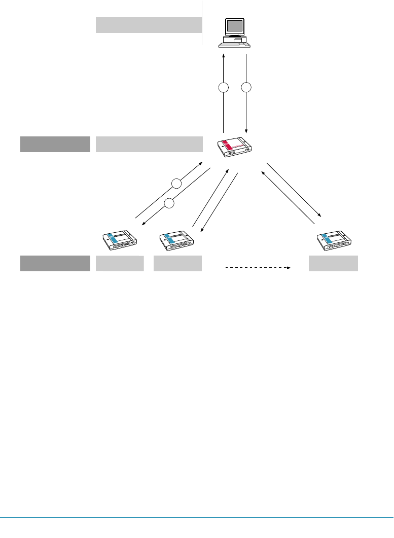
The data flow across the network is controlled by the primary station; the DD6000 net-
work controller, as depicted in figure 3.1. The controller interrogates each decoder in
turn to see if it wishes to transmit data. This is called polling. A decoder can only trans-
mit data when polled by the controller, data flow 1 in figure 3.1 . The data is packed in
frames; the OSENET-frame. Apart from the actual data, these frames contain informa-
tion about the data address, data type, data synchronisation, etc. Data sent by a sta-
tion is buffered at the controller in order to be sent to the host computer, data flow 3.
However, first the controller has to convert the OSENET-frame to a frame suitable for
the controller-host data link. The data frame format for the host controller data frame
can be configured in part 4, and depends on the program running on the host compu-
ter. At the host the data is processed and a response is sent back to the controller, data
flow 4. At least this response contains information about the destination of the data.
At the controller the data frame is converted back to the OSENET-frame. Finally the
controller sends this information to the station in question, data flow 2. Data flow 1 and
2 will be described in this section. The host-controller data link (flow 3 and 4) will exten-
sively be described in part 4 of this manual.
22 THE OSENET SYSTEM
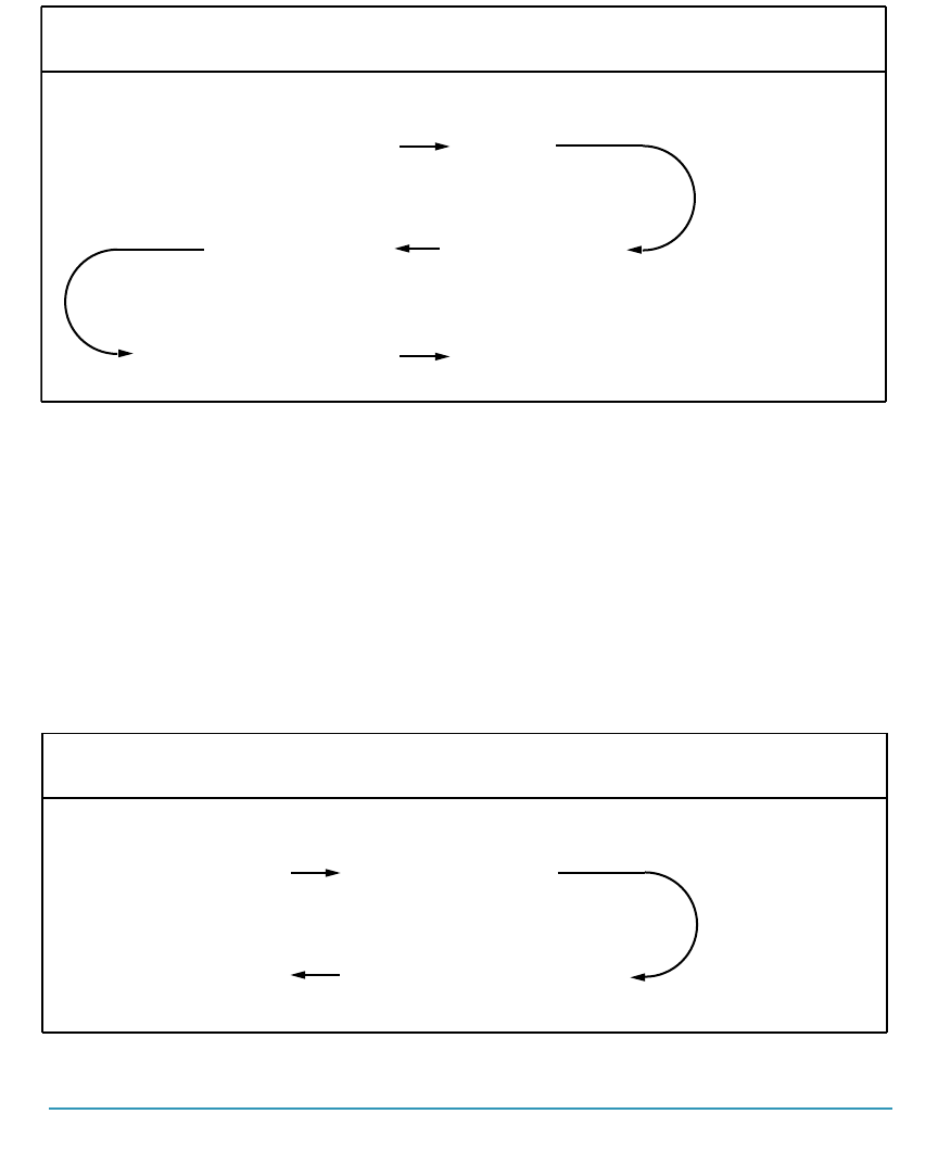
decoder - controller data exchange( data flow 1 in fig. 3.1)
The protocol for sending data from a decoder station to the controller (data flow 1 in
figure 3.1) is depicted in table 3.1. After receiving the poll, it takes the decoder station td
seconds to react with the data. Once all data is received by the controller, it sends back
a <RECEIVE READY> , after seconds tc, to acknowledge the data reception. The td and
tc are the turnaround times for the decoder and controller. The td is the time it takes for
the decoder to process the data (<POLL>) received from the controller and send back
a response. The tc is the time it takes for the controller to process the data received
from the decoder and send back a response. For both decoder and controller these
times are 200 µsec.
With a <POLL> and a <RECEIVE READY> 2 and 4 bytes are involved respectively, as
indicated in table 3.1. The M+6 consists of a message length of M bytes plus 6 bytes
overhead. The overhead is used for the station address, network control field, device
control, station control, frame check and a flag to mark the end of a frame.
network controller
station 2
station 1 station n
4
polling all n stations
primary station
tc
td
th
tc
secondary stations
3
1
2
HOST
Figure 3.1 Data flows considered for decoder-host communication.
THE OSENET SYSTEM 23
controller - decoder data exchange( data flow 2 in fig. 3.1)
To send a message from the controller to a decoder station the data exchange as
shown in table 3.2 is followed. Data is sent from the controller to the decoder station.
After td seconds the station transmits a <RECEIVE READY> to acknowledge the data
reception. Again the number of bytes involved are indicated in the right-hand column.
CONTROLLER
<POLL>
<RECEIVE READY>
direction
STATION
<DATA>
max. bytes involved
2
M+6
4
td
tc
Table 3.1 Station - controller data exchange sequence.
CONTROLLER
<DATA>
direction
STATION
<RECEIVE READY>
max. bytes involved
M+6
4
td
Table 3.2 Controller - station data exchange sequence.
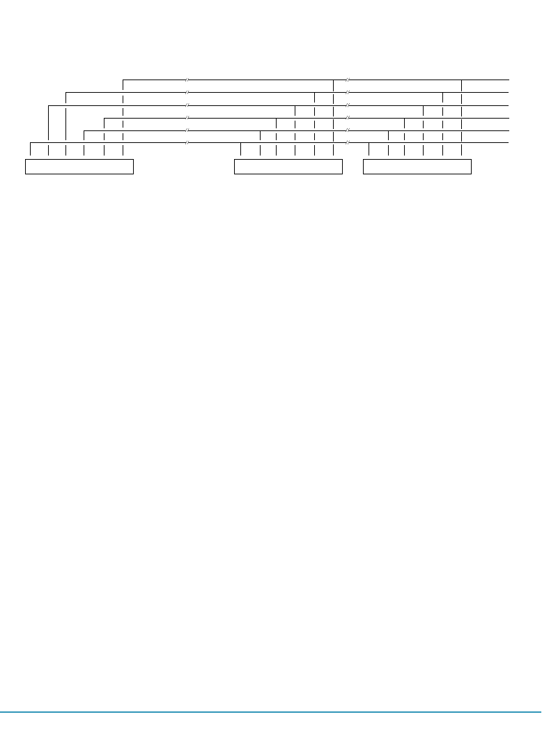
24 THE OSENET SYSTEM
station s
controller
poll for station s poll for station s+1
EOP
from station s
station s
controller
poll for station s poll for station s+1
DATA
from station s
station s sends
data after a poll
station s
controller
poll for station s poll for station s+1
poll time-out for station s
no data from station,
station sends an EOP
1)
2)
the controller polls the next station
after a poll time-out has occured
3)
time
time
time
Figure 3.1 Possible reactions of a decoder on a poll.

THE OSENET SYSTEM 25
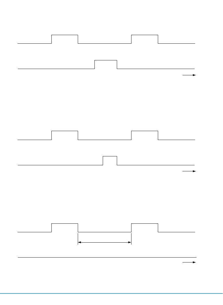
polling stations
To poll the decoder station, the controller simply sends a message to each station
in turn, inquiring whether or not the stations have data to send. These polling mes-
sages contain the address of the station inquired. Each decoder station knows its own
address and only responds to its own polls, although it receives all polls. If the a
decoder station has data to send it send data according to table 3.1. If not, it sends
back an EOP-byte(=End of Poll). If neither data nor an <EOP>-byte is sent by the
decoder, the controller will generate a poll for the next station after a poll time-out, as
depicted in figure 3.2. In this way all decoder station are polled.
The time it takes to finish a complete sequence of polling a station, receiving an End
of Poll and generating a poll for the next station is called the poll execution time. The
poll cycle time is the time required to poll al stations on the network without exchanging
data. In formula:
In which: - tpc poll cycle time
- tpe poll execution time
- tp poll transmit time (2 bytes)
- teop End of Poll transmit time (1 byte)
- tpg poll generation time, the delay between an <EOP> reception
and the transmission of a new poll (250µs for OSENET).
- tbo transmit time for one byte
- N number of stations
tpc = Ntpe = N(tp + teop + tpg) = N(3tb+ tpg) = N*515µs.
26 THE OSENET SYSTEM
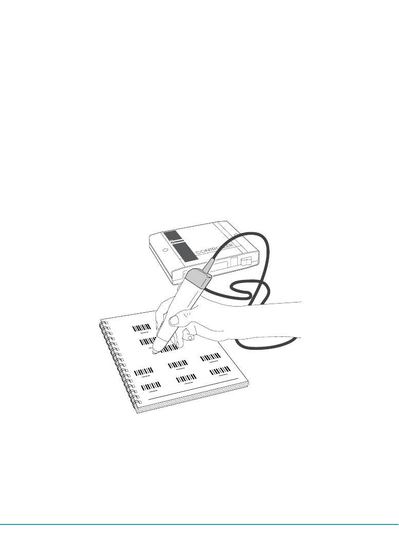
3.2 PROGRAMMING THE OSENET NETWORK
Once the network is installed in accordance with the guidelines in section 2.3, several
features of the network can be programmed by bar code menu, or via the host com-
puter as explained in section 4.X. If the controller is set with bar code menus, the bar
codes in this section can be scanned with a bar code reader connected to port I1 of
the controller. How to set the parameters is described extensively in section 4.1 of the
"User's manual DD6000". A table with read direct labels is present in appendix B of this
manual. This table is identical to the table in the decoder manual.
Appendix X+1 features labels which affect both the OSENET and/or the controller-host
data link. Scanning these labels makes this section partly superfluous.
Figure 3.2 With a bar code reader connected to port I1 of the controller OSENET
features can be programmed.

THE OSENET SYSTEM 27
For some features the table with read direct labels (Appendix B) should always be
used, whereas for other features a selection can be made out of labels available on the
page in question.
programmable features
set the network baudrate
set the number of stations
set station off-line
set station on-line
test RAM
test EEPROM
set the response time
set the number of errors
set the recovery time
page
28-30
30-31
30-31
30-31
30-31
30-31
32-33
34-35
36-37
selection with
Read Direct Labels
Appendix C
*
*
*
Table 3.3 Programmable features of OSENET.

28 THE OSENET SYSTEM
set the network baud rate - The baud rate (transmission speed) for OSENET is the
number of bits transmitted per second. The baud rate can be vary in steps between
75 and 125K kbps (=bits per second). Make sure that the baud rate of port O1 of all
decoders on the network correspond to the baud rate set here. (please refer to the
"User's manual of the DD6000" page 56-57 to set the decoder baud rate).

*//2*
set the network baud rate:
---> *//2*
*$00* *$01* *$02*
*$00* *$01* *$02*
75 110 150
*$03* *$04* *$05*
*$03* *$04* *$05*
300 600 1200
*$06* *$07* *$08*
*$06* *$07* *$08*
2400 4800 9600
*$09* *$0A* *$0B*
*$09* *$0A* *$0B*
19200 31250 38400
*$0C* *$0D*
*$0C* *$0D*
62500 125K
PROGRAMMER'S GUIDE 29
** */+0* */+1* */+2*
enter menu exit menu restore setup save setup

30 THE OSENET SYSTEM
set first station in the range - A decimal value should be read from the table with
reaqd direct labels in Appendix B. This label corresponds to the lowest number in the
range of decoder stations.
set last station in the range - A decimal value should be read from the table with read
direct labels in Appendix B. This label corresponds to the highest number in the range
of decoder stations.
Please notice that all stations outside the specified range will be disabled.
disable station - Decoder stations not used can be disabled. After this label has been
read, a decimal value (=the station that should be disabled) should be read from the
table with read direct labels.
If a station is switched off but is not disabled, it delays the poll cycle with a poll time out
for the station considered. An disabled station is not polled.
enable station - Disabled decoder stations can be enabled by reading this bar code
label. After the label has been read, a decimal value (= the station that should be ena-
bled) should be read from the table with read direct labels.
test RAM - Test the Static RAM of the network controller:
- high beep is OK!
- low beep is not OK!
test EEPROM - Test the EEPROM of the network controller:
- high beep is OK!
- low beep is not OK!
Please refer to the trouble shooting section if one of these parts of memory are
not OK!

*//H*
set first station in the range: ---> *//H* --->
*//A*
set last station in the range: ---> *//A* --->
*//F*
disable station: ---> *//F* --->
*//G*
enable station: ---> *//G* --->
*//D*
test RAM: *//D*
*//E*
test EEPROM: *//E*
PROGRAMMER'S GUIDE 31
** */+0* */+1* */+2*
enter menu exit menu restore setup save setup

32 THE OSENET SYSTEM
set the response time - The period of time in which a controller has to receive a reac-
tion from a polled station. If no reaction is received a poll time-out will occur. Notice that
for this time the network baud rate and cable length should be considered. After this
label has been read, a label from the table with read direct labels should be read.
response time = decimal value of read direct label x 0.5 ms.
This time is different from the response time determined in section 5.
example:
The first read direct label is *$00*
000 -NUL- *$00*
The response time is 0 x 0.5 ms. = 0 ms. This is the minimum response time.
The first read direct label is *$FF*
255 -switch- *$FF*
The response time is 255 x 0.5 ms. = 127.5 ms. This is the maximum response time.
set the number of errors - If the controller receives incorrect data from a station, or
no reaction at all, the controller can switch off the decoder in question temporarily. With
this option you can set the number of allowed errors which a controller can receive from
a station before being switched-off. After this label has been read, a label from the table
with read direct alabesl should be read.
The decimal value of a label indicates the selected number of errors.
The maximum number of errors allowed is 51.
set the recovery time - The controller tries to switch stations which are off-line, on-line
again after a period of time selected with this options.
recovery time = decimal value of read direct label x 0.1 ms.

*//3*
set the response time: ---> *//3* --->
*//6*
set the number of errors: ---> *//6* --->
*//5*
set the recovery time: ---> *//5* --->
PROGRAMMER'S GUIDE 33
** */+0* */+1* */+2*
enter menu exit menu restore setup save setup

34

controller-host communication protocol
4
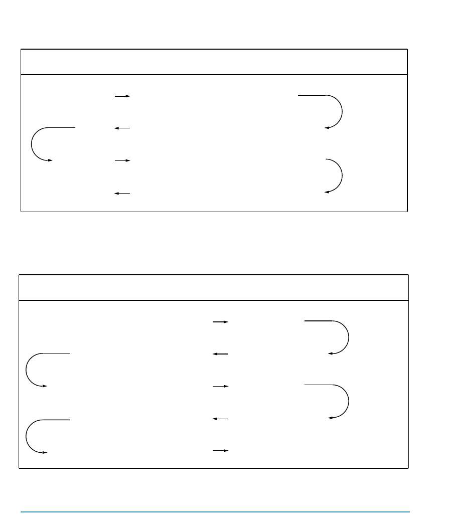
36 CONTROLLER-HOST COMMUNICATION PROTOCOL
HOST
<EOT> <FS> <ENQ>
<1 CHAR> <ACK>
direction
max. bytes involved
3
M+11
2
1
t
h
t
c
CONTROLLER
<..4 CHARS..> <STX><DATA> <..4 CHARS..> <ETX> <LRC>
<EOT>
t
c
Table 4.1 Controller - host data exchange sequence.
HOST
<EOT> <GS> <ENQ>
<1CHAR> <STX> <DATA> <1CHAR> <ETX> <LRC>
<EOT>
direction
max. bytes involved
3
5
M+5
5
1
t
h
t
c
CONTROLLER
<..4CHAR..> <ACK>
<..4CHAR..> <ACK>
t
c
t
h
Table 4.2 Host - controller data exchange sequence.

CONTROLLER-HOST COMMUNICATION PROTOCOL 37
host - controller communication
For host-controller communication either the RS232 or RS 422 can be used. If the
distance between the controller and the host computer is long, the latter is preferred.
Depending on the program running on the host computer, the communication protocol
should be set. Three protocols are available:
• free running
• ANSI X3.28
• Intermec mode D
In case free running is selected, no protocol is active and data is transmitted in spite of
control signals.
ANSI X3.28 is a user configurable protocol. It is based on the ANSI X3.28 standard,
sub-category 2.4, A4. This protocol features: two way alternate non-switched multipoint
operation, polling/selection mechanism, ACK/NAK handshaking and longitudinal redun-
dancy check.

38

THE OSENET SYSTEM 39
time analysis of OSENET
5

40

TIME ANALYSIS OF OSENET 41
In this section formulas are derived which can be used to calculate the response time
for the network designed. Roughly, the response time is defined as the time a DD6000-
station has to wait to receive a response from the host after data has been read. The
response time depends on many things such as network baud rate, host-controller
baud rate, message length, number of stations, overhead, etc.
Once the network is installed and the host-controller protocol is configured, the formu-
las derived in this section can be used to calculate a response time for your network
to check whether it is quick enough. If the calculated response time turns out to be too
long, a few guidelines to reduce this time are indicated at the end of this section.
First the time to send a message for all data flows indicated in figure 3.1 will be calcu-
lated.
The default communication parameters for the OSENET network are:
Baud rate : 125000 baud
Data format : 9 bit
Stop bit : 1 bit
Start bit : 1 bit
From these parameters, the time it takes to transmit a single data byte can be calcu-
lated, by dividing the bits in the byte by the baud rate:
In which tbo is the time to transmit a single byte across the network.
decoder - controller data exchange( data flow 1 in fig. 3.1)
The time it takes to transmit a message of length M from the decoder to the control-
ler, and to have this message acknowledged, can be derived from the data exchange
sequence indicated table 3.1. This time is given as:
tbo = start bit + stop bit + data bits = 11 = 88 µsec. baud rate 125 K (1)
tsc = tpoll + td + tdata + tc + trr (2)

42 TIME ANALYSIS OF OSENET
In which: - tsc time to transmit a message from a decoder to the controller
- tpoll poll transmit time
- td turnaround time for the decoder
- tdata time to transmit data to the controller
- tc turnaround time for the controller
- trr time to transmit an <rr> acknowledgement
With equation (1), the number of bytes for the data exchange and the turnaround times
for the decoder and controller equation (2) leads to:
In which: - tsc time to transmit a message from a decoder to the controller
- tbo time to transmit one byte
- td turnaround time for the decoder
- M message length
- tc turnaround time for the controller
contoller - decoder data exchange( data flow 2 in fig. 3.1)
The time needed to send a frame to the station can be derived from the data exchange
sequence indicated in table 3.2. This time is given as:
In which: - tcs time to transmit a message from the controller to a decoder
- tdata time to transmit data to a decoder
- td turnaround time for the decoder
- trr time to transmit an <rr> acknowledgement
tcs = tdata + td + trr (4)
tsc = 2tbo + td + (M+6)tbo + tc + 4tbo = 1.456 ms. + 88M µs. (3)

TIME ANALYSIS OF OSENET 43
With equation (1), the number of bytes for the data exchange and the turnaround time
for the decoders equation (4) leads to:
In which: - tcs time to transmit a message from the controller to a decoder
- tbo time to transmit one byte
- td turnaround time for the decoder
- M message length
controller - host data exchange( data flow 3 in fig. 3.1)
Because the controller should be able to exchange data with any program running on a
host computer, the protocols for this data link are highly configurable. In this section the
worst case data exchanges for this data link are postulated.
For the host interface parameters the default settings are used:
Baud rate : 9600 baud
Data format : 7 bit
Start bit/Stop bit : 0 bit/2 bit
Parity bit : even
Interface : RS232 (no hardware handshaking)
From these parameters, the time it takes to transmit a single data byte can be calcu-
lated, by dividing the bits in the byte by the baud rate:
In which tbh is the time to transmit a single byte across the host-controller data link.
The data exchange sequence for sending a message with length M from the network
controller to the host computer is depicted in table 4.1 in chapter 4. The indication
<1 char> and <..4char..> refers to the additional characters which can be employed to
configure the protocol required for the program running on the host computer.
The total time to transmit a message to the host and to react on the hosts acknowl-
edgement with an <EOT> is given as:
baud rate 9600
tbh = stop bits + parity bit + data bits = 10 = 1.04 ms. (6)
tch = th.enq + 2tc + tdata + th + th.ack+ tc.eot (7)

44 TIME ANALYSIS OF OSENET
In which: - tch time to transmit a message from the controller to the host
- th.enq time to transmit the <EOT><FS><ENQ> sequence
- tc turnaround time for the controller
- tdata time to transmit data with additional control characters
- th turnaround time for the host
- th.ack time to transmit an <ACK>
- tc.eot time to transmit an <EOT>
With equation (6), the number of bytes for the data exchange and the turnaround times
for the controller and host( assumed to be 200µs.), equation (7) leads to:
In which: - tch time to transmit a message from the controller to the host
- tbh time to transmit one byte
- tc turnaround time for the controller
- th turnaround time for the host
- M message length
host-controller data exchange( data flow 4 in fig. 3.1)
To send a message from the host computer to the network controller the data exchange
sequence as shown in table 4.2 is followed. The time needed to send a message of
length M to the controller is:
In which: - thc time to transmit a message from the host to the controller
- th.enq time to transmit an enquiry to the controller
- tc turnaround time for the controller
- tc.ack time to transmit an acknowledgement to the host
- tdata time to transmit data to the controller
- th turnaround time for the host
- th.eot time to transmit an <EOT>
thc = th.enq + 2tc + 2tc.ack+ tdata + 2th + th.eot (9)

TIME ANALYSIS OF OSENET 45
With equation (6), the number of bytes for the data exchange and the turnaround times
for the controller and host( assumed to be 200µs.), equation (9) leads to:
In which: - thc time to transmit a message from the host to the controller
- tbh time to transmit one byte
- tc turnaround time for the controller
- th turnaround time for the host
- M message length
With the equations (3), (5), (8) and (10) a worst case time response for one of N sta-
tions can be estimated. The worst case time is the time which elapses between sending
and receiving data on a station. In this case all N stations are reading data, whereas
the considered station is the last one to send its message. All messages are sent from
the controller to the host, processed by the host and sent back to the controller. The
considered station is the last one to receive its data. Let the number of stations be 50
(N=50) and the message length be 10 characters (M=10) for all stations. Then:
Apart from the fact that the change of occurence is virtually impossible, the data trans-
missions across both data links are running almost parallel, the change that all stations
have data to transmit at the same time is not very large.
example
The latter consideration is not very realistic. In this example a formula for a typical
response time, still on the pessimistic side, will be derived. Assumed that:
- p% of all N decoders is transmitting data.
- the length of the data is 10 characters.(M=10).
- for the decoder-controller data link:125Kbps, 9 data bits, 1 start bit,
1 stop bit.
- the baud rate for the host-controller data link is 38K4 kbps.
- for the host-controller data link: 2 stop bits, 1 parity bit, 7 data bits.
- the prefix for all control character for the host-controller data link is
one character.
thc = 3tbh + 2tc + (M+5)tbh + 2th + 10tbh + tbh = 20.59 ms. + 1.04M ms. (10)
tresp = 50tsc(M=10) + 50tch(M=10) + 50thc(M=10) + 50tcs(M=10) = 3.2 s. (11)

46 TIME ANALYSIS OF OSENET
- poll execution time tpe= 515µs.(section 3.1)
With these assumptions tsc= 2.34ms. , tcs= 1.96ms., tch=6.07ms., thc=6.79ms.
Not all stations want to transmit data. However, all stations are polled. Suppose that
the first (100-p)% of the stations are polled and the first p% of the station have data to
send. Once this data has arrived at the controller, it is sent to the host. From the host it
is sent back to the controller, and back to the station in question. The data transmission
on all data links happen sequential in time. In formula:
T
res,typ = (1-p)Ntpe + Nptsc + Nptch + Npthc + (1-p)Ntpe + Nptcs
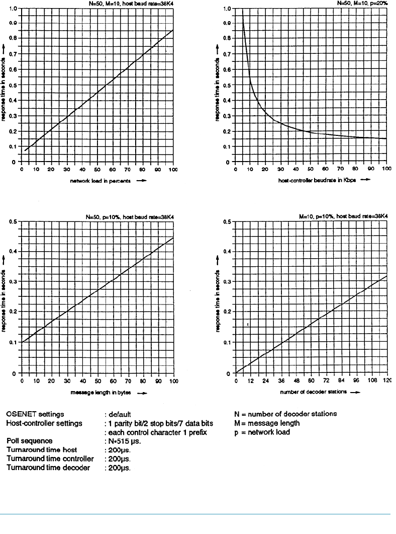
The diagrams on the next page give an impression of the speed of a network, based
on the latter formula. In each figure only one parameter is a variable, whereas the other
parameters are constants. These constant values are indicated in the upper left corner
of each diagram.
In appendix C a listing of a BASIC-file is enclosed. This program calculates a more pre-
cise response time for your network. An extensive description of the program is given at
the beginning of the appendix.
Reduction of response time
If the response time turns out to be too long the following guidelines should be followed:
• Increase the host controller baud rate. Although the default value
for the baud rate is 9600 baud, most computers can handle a baud
rate of 38K4 bps easily.
• Reduce the overhead to a minimum. The data frame for host-con-
troller communication is highly programmable. Control characters
can sometimes be preceded by 4 characters. Only use this feature
if strictly necessary. To a lesser degree this also counts for the
OSENET data link.
• Stations switched off should be set off-line. To prevent the con-
troller from polling station which are switched off, the option on page
30-31 should be used to reduce the poll sequence of the network.
TIME ANALYSIS OF OSENET 47
Figure 5.1 The response time of a network as a function of : the network load, the host
baud rate, message length and the number of decoders

48

49
pin assignment of ports
A

50

This appendix contains the pin assignment of the data input port I1 and communica-
tion ports O1 and O2. Indication of signalling direction (in/out) is related to the DD6000
controller. See figure A-1 description of the connector used.
A.1 PIN ASSIGNMENT PORT O1
pin in/out description
1. Frame ground connected to housing
2. TxD RS232 out Transmitted Data: transmit data to host computer
3. RxD RS232 in Received Data: receive data from host computer
4. RTS RS232 out Request To Send: desire (demand) to transmit data
5. CTS RS232 in Clear To Send: permission of host to transmit data
6. Not connected
7. Logic ground Signal Ground
8. Not connected
9. T+ RS485 out Transmit differential voltage
10. T- RS485 out Transmit differential voltage
11. TR+ RS485 in/out Transmit/Receive differential voltage
12. TR- RS485 in/out Transmit/Receive differential voltage
13. Not connected
14. Not connected
15. Not connected
16. Not connected
17. Not connected
18. Not connected
19. Not connected
20. Not connected
21. Not connected
22. Not connected
23. Not connected
24. Not connected
25. +5V in/out Vcc
PIN ASSIGNMENT OF PORTS 51
A.2 PIN ASSIGNMENT PORT O2
pin in/out description
1. Frame ground connected to housing
2-6. Not connected
7. Logic ground Signal Ground
8. Not connected
9. TR+ RS485 in/out Transmit/Receive differential voltage
10. TR- RS485 in/out Transmit/Receive differential voltage
11. T+ RS485 out Transmit differential voltage
12. T- RS485 out Transmit differential voltage
13-24. Not connected
25. +5V in/out Vcc
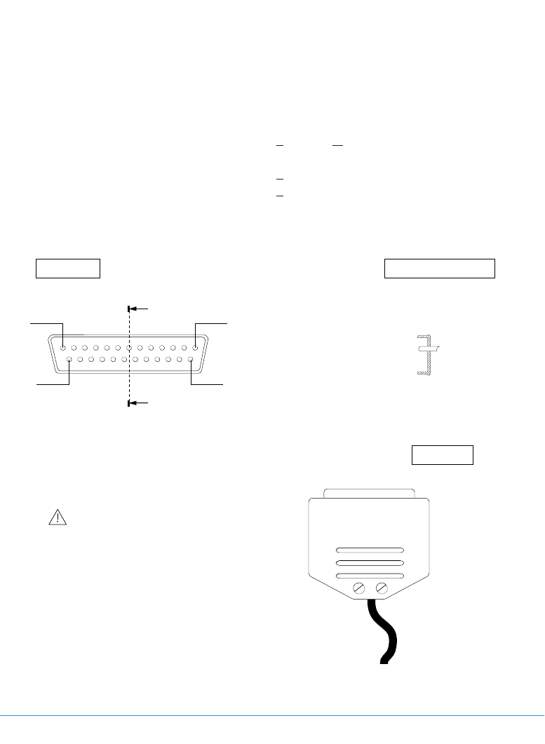
52 PIN ASSIGNMENT OF PORTS
pin 1 pin 13
pin 14 pin 25
A
A
pin assignment is mirrored
for female connector
front view cross-section A-A
top view
for port O1 use a male type connector
for port O2 use a female type connector
Figure A-1. Standard DB25 connector used for port O1 and port O2.
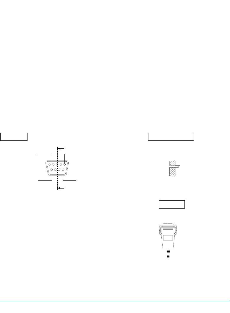
A.3 PIN ASSIGNMENT PORT I1
See figure A-2 description of the connector used.
pin in/out description
1. start of scan in signal from peripheral to indicate a scan has started
2. TTL in in data from peripheral
3. Good read out confirmation of a good read by the decoder
4. Motor failure sense in signal for a defective motor
5. Trigger switch in signal for triggering DD6000
6. LED enable out signal to enable scanner after trigger
7. Ground
8. Ground
9. +5 Volt
PIN ASSIGNMENT OF PORTS 53
A
A
pin 5 pin 1
pin 9 pin 6
front view cross-section A-A
top view
for port I1 use female type connetor.
Figure A-2. Standard DB9 connector used for port I1.

54

55
table with read direct labels
B

56
TABLE WITH READ DIRECT LABELS 57
The read direct labels can be used to:
1. enter numerical data from 0 to 255.(decimal indication)
example: if the label below is read after the "set station off-line" has
been read, station 8 will be set off-line.
2. set alternative control-characters.(ASCII indication)
example: if a poll from the host should be preceded by an ASCII-
character <BS>, the label below should be read.
3. find the hexadecimal representative of the bar code labels
example: reading the code with hexadecimal value *$08* after the label
"set network baud rate, sets the baud rate 9600 baud. If it is
read after the "set response time "-label has been read, the
maximum allowed response time will be 4.5 ms.
*$33*
008 -BS- *$08*
decimal ASCII hexadecimal

58 TABLE WITH READ DIRECT LABELS
*$00* *$08* *$10*
000 -NUL- *$00* 008 -BS- *$08* 016 -DLE- *$10*
*$01* *$09* *$11*
001 -SOH- *$01* 009 -HT- *$09* 017 - DC1- *$11*
*$02* *$0A* *$12*
002 -STX- *$02* 010 -LF- *$0A* 018 -DC2- *$12*
*$03* *$0B* *$13*
003 -ETX- *$03* 011 -VT- *$0B* 019 -DC3- *$13*
*$04* *$0C* *$14*
004 -EOT- *$04* 012 -FF- *$0C* 020 -DC4- *$14*
*$05* *$0D* *$15*
005 -ENQ- *$05* 013 -CR- *$0D* 021 -NAK- *$15*
*$06* *$0E* *$16*
006 -ACK- *$06* 014 -SO- *$0E* 022 -SYN - *$16*
*$07* *$0F* *$17*
007 -BEL- *$07* 015 -SI- *$0F* 023 -ETB- *$17*

TABLE WITH READ DIRECT LABELS 59
*$18* *$21* *$2A*
024 -CAN- *$18* 033 -!- *$21* 042 -*- *$2A*
*$19* *$22* *$2B*
025 -EM- *$19* 034 -"- *$22* 043 - + - *$2B*
*$1A* *$23* *$2C*
026 -SUB- *$1A* 035 -#- *$23* 044 -,- *$2C*
*$1B* *$24* *$2D*
027 - ESC - *$1B* 036 -$- *$24* 045 - - - *$2D*
*$1C* *$25* *$2E*
028 -FS - *$1C* 037 -%- *$25* 046 - . - *$2E*
*$1D* *$26* *$2F*
029 -GS- *$1D* 038 -&- *$26* 047 - / - *$2F*
*$1E* *$27* *$30*
030 -RS- *$1E* 039 -'- *$27* 048 - 0 - *$30*
*$1F* *$28* *$31*
031 -US- *$1F* 040 - ( - *$28* 049 - 1 - *$31*
*$20* *$29* *$32*
032 -SP- *$20* 041 -)- *$29* 050 -2- *$32*

60 TABLE WITH READ DIRECT LABELS
*$33* *$3C* *$45*
051 -3- *$33* 060 - < - *$3C* 069 -E- *$45*
*$34* *$3D* *$46*
052 -4- *$34* 061 -=- *$3D* 070 -F- *$46*
*$35* *$3E* *$47*
053 -5- *$35* 062 - > - *$3E* 071 - G - *$47*
*$36* *$3F* *$48*
054 -6- *$36* 063 -?- *$3F* 072 -H- *$48*
*$37* *$40* *$49*
055 -7- *$37* 064 -@- *$40* 073 -I- *$49*
*$38* *$41* *$4A*
056 -8- *$38* 065 -A- *$41* 074 -J- *$4A*
*$39* *$42* *$4B*
057 -9- *$39* 066 -B- *$42* 075 -K- *$4B*
*$3A* *$43* *$4C*
058 -:- *$3A* 067 -C- *$43* 076 -L- *$4C*
*$3B* *$44* *$4D*
059 -;- *$3B* 068 -D- *$44* 077 -M- *$4D*

TABLE WITH READ DIRECT LABELS 61
*$4E* *$57* *$60*
078 -N- *$4E* 087 -W- *$57* 096 - ' - *$60*
*$4F* *$58* *$61*
079 -O- *$4F* 088 -X- *$58* 097 -a- *$61*
*$50* *$59* *$62*
080 -P- *$50* 089 -Y- *$59* 098 -b- *$62*
*$51* *$5A* *$63*
081 -Q- *$51* 090 -Z- *$5A* 099 -c- *$63*
*$52* *$5B* *$64*
082 -R- *$52* 091 -[- *$5B* 100 -d- *$64*
*$53* *$5C* *$65*
083 -S- *$53* 092 -\- *$5C* 101 -e- *$65*
*$54* *$5D* *$66*
084 -T- *$54* 093 -]- *$5D* 102 -f- *$66*
*$55* *$5E* *$67*
085 -U- *$55* 094 -^- *$5E* 103 -g- *$67*
*$56* *$5F* *$68*
086 -V- *$56* 095 -_- *$5F* 104 -h- $68*

62 TABLE WITH READ DIRECT LABELS
*$69* *$72* *$7B*
105 -i- *$69* 114 -r- *$72* 123 -{- *$7B*
*$6A* *$73* *$7C*
106 -j- *$6A* 115 -s- *$73* 124 -|- *$7C*
*$6B* *$74* *$7D*
107 -k- *$6B* 116 -t- *$74* 125 -}- *$7D*
*$6C* *$75* *$7E*
108 -l- *$6C* 117 -u- *$75* 126 -~- *$7E*
*$6D* *$76* *$7F*
109 -m- *$6D* 118 -v- *$76* 127 -DEL- *$7F*
*$6E* *$77* *$80*
110 -n- *$6E* 119 -w- *$77* 128 -shiftl make- *$80*
*$6F* *$78* *$81*
111 -o- *$6F* 120 -x- *$78* 129 -shiftr make- *$81*
*$70* *$79* *$82*
112 -p- *$70* 121 -y- *$79* 130 -altl make- *$82*
*$71* *$7A* *$83*
113 -q- *$71* 122 -z- *$7A* 131 -altr make- *$83*

TABLE WITH READ DIRECT LABELS 63
*$84* *$8D* *$96*
132 -ctrll make- *$84* 141 -ctrlr break- *$8D* 150 -<F7>- *$96*
*$85* *$8E* *$97*
133 -ctrlr make- *$85* 142 -num break- *$8E* 151 -<F8>- *$97*
*$86* *$8F* *$98*
134 -num make- *$86* 143 -all break- *$8F* 152 -<F9>- *$98*
*$87* *$90* *$99*
135 -all make- *$87* 144 -<F1>- *$90* 153 -<F10>- *$99*
*$88* *$91* *$9A*
136 -shftl break- *$88* 145 -<F2>- *$91* 154 -<F11>- *$9A*
*$89* *$92* *$9B*
137 -shftr break- *$89* 146 -<F3>- *$92* 155 -<F12>- *$9B*
*$8A* *$93* *$9C*
138 -altl break- *$8A* 147 -<F4>- *$93* 156 -<F13>- *$9C*
*$8B* *$94* *$9D*
139 -altr break- *$8B* 148 -<F5>- *$94* 157 -<F14>- *$9D*
*$8C* *$95* *$9E*
140 -ctrll break- *$8C* 149 -<F6>- *$95* 158 -<F15>- *$9E*

64 TABLE WITH READ DIRECT LABELS
*$9F* *$A8* *$B1*
159 -<F16>- *$9F* 168 - - *$A8* 177 - - *$B1*
*$A0* *$A9* *$B2*
160 - - *$A0* 169 - - *$A9* 178 - - *$B2*
*$A1* *$AA* *$B3*
161 - - *$A1* 170 - - *$AA* 179 - - *$B3*
*$A2* *$AB* *$B4*
162 - - *$A2* 171 - - *$AB* 180 - - *$B4*
*$A3* *$AC* *$B5*
163 - - *$A3* 172 - - *$AC* 181 - - *$B5*
*$A4* *$AD* *$B6*
164 - - *$A4* 173 - - *$AD* 182 - - *$B6*
*$A5* *$AE* *$B7*
165 - - *$A5* 174 - - *$AE* 183 - - *$B7*
*$A6* *$AF* *$B8*
166 - - *$A6* 175 - - *$AF* 184 - - *$B8*
*$A7* *$B0* *$B9*
167 - - *$A7* 176 - - *$B0* 185 - - *$B9*

TABLE WITH READ DIRECT LABELS 65
*$BA* *$C3* *$CC*
186 - - *$BA* 195 - - *$C3* 204 - .- *$CC*
*$BB* *$C4* *$CD*
187 - - *$BB* 196 - - *$C4* 205 - - *$CD*
*$BC* *$C5* *$CE*
188 - - *$BC* 197 - - *$C5* 206 - - *$CE*
*$BD* *$C6* *$CF*
189 - - *$BD* 198 - - *$C6* 207 - - *$CF*
*$BE* *$C7* *$D0*
190 - - *$BE* 199 - - *$C7* 208 - - *$D0*
*$BF* *$C8* *$D1*
191 - - *$BF* 200 - - *$C8* 209 - - *$D1*
*$C0* *$C9* *$D2*
192 - - *$C0* 201 - - *$C9* 210 - -* $D2*
*$C1* *$CA* *$D3*
193 - - *$C1* 202 - - *$CA* 211 - - *$D3*
*$C2* *$CB* *$D4*
194 - - *$C2* 203 - - *$CB* 212 - - *$D4*

66 TABLE WITH READ DIRECT LABELS
*$D5* *$DE* *$E7*
213 - - *$D5* 222 - - *$DE* 231 - - *$E7*
*$D6* *$DF* *$E8*
214 - - *$D6* 223 - - *$DF* 232 - - *$E8*
*$D7* *$E0* *$E9*
215 - - *$D7* 224 - - *$E0* 233 - - *$E9*
*$D8* *$E1* *$EA*
216 - - *$D8* 225 - - *$E1* 234 - - *$EA*
*$D9* *$E2* *$EB*
217 - - *$D9* 226 - - *$E2* 235 - - *$EB*
*$DA* *$E3* *$EC*
218 - - *$DA* 227 - - *$E3* 236 - - *$EC*
*$DB* *$E4* *$ED*
219 - - *$DB* 228 - - *$E4* 237 - - *$ED*
*$DC* *$E5* *$EE*
220 - - *$DC* 229 - - *$E5* 238 - - *$EE*
*$DD* *$E6* *$EF*
221 - - *$DD* 230 - - *$E6* 239 - - *$EF*

TABLE WITH READ DIRECT LABELS 67
*$F0* *$F6* *$FC*
240 - - *$F0* 246 - - *$F6* 252 - - *$FC*
*$F1* *$F7* *$FD*
241 - - *$F1* 247 - - *$F7* 253 - eos - *$FD*
*$F2* *$F8* *$FE*
242 - - *$F2* 248 - - *$F8* 254 - delay - *$FE*
*$F3* *$F9* *$FF*
243 - - *$F3* 249 - - *$F9* 255 - switch - *$FF*
*$F4* *$FA*
244 - - *$F4* 250 - - *$FA*
*$F5* *$FB*
245 - - *$F5* 251 - - *$FB*

68

69
listing response time program
C

70

The following program can be used to calculated the response time for your network.
For several parameters of both data links a value should be entered. ( Most values can
be set with the bar code options in section 3 and 4). By pressing the <CR>-key the
default value for a parameter is selected. An other value can be entered if the <ESC>-
key is pressed. First a description of the parameter values to be entered is given.
****************** OSEnet data link settings *******************
number of decoder stations: The number of decoders connected to your net-
work. Enter a value 1-126.
OSEnet baud rate : The transmission speed across the network.
Default is 125Kbps.
average message length : The average length of data send from the
decoder stations to the host. For instance, if
most of the time UPCA codes are read, the
message length is 12.
network load in % : If 50 decoders are on-line and on 5 decoders a
total of 10 scanners are reading labels simulta-
neously, the network load is 20%.
************** host-controller data link settings **************
host baud rate : The baud rate for the host-controller data link.
Default value is 9600 bps. A transmission speed
of 38400 baud is recommended.
number of data bits : The number of data bits can be 7 or 8. Default
is 7 data bits.
number of stop bits : The number of stop bits can be 1 or 2. Default is
2 stop bits.
LISTING RESPONSE TIME PROGRAM 71

72 LISTING RESPONSE TIME PROGRAM
please refer to table 4.2 for host-controller data exchange.
number of bytes for from host poll:
The number of bytes for a poll can be 1, 2 or 3.
number of bytes for first to host acknowledgement:
The number of bytes is can vary between 1and 5.
number of bytes accompanying the data bytes:
The number of additional bytes is can vary
between 3 and 5.
number of bytes for second to host acknowledgement:
The number of bytes is can be 1 or 5.
BASIC PROGRAM LISTING
10 CLS
20 PRINT "************************** OSEnet data link settings **************************"
30 PRINT ""
40 INPUT "number of decoder stations: ", N
50 PRINT "-"
60 PRINT "OSEnet baud rate : "
70 PRINT "<CR>=125000, <ESC>=value"
80 GOSUB 1230
90 IF A$ = CHR$(27) THEN 120
100 OB = 125000
110 GOTO 130
120 INPUT "your value: "; OB
130 PRINT "-"
140 A$ = ""
150 PRINT "average message length : "
160 PRINT "<CR>=10, <ESC>=value"
170 GOSUB 1230
180 IF A$ = CHR$(27) THEN 210
190 M = 10
200 GOTO 220

LISTING RESPONSE TIME PROGRAM 73
210 INPUT "your value :"; M
220 PRINT "-"
230 A$ = ""
240 PRINT "network load in % : "
250 PRINT "<CR>=10%, <ESC>=value"
260 GOSUB 1230
270 IF A$ = CHR$(27) THEN 300
280 p = 10
290 GOTO 310
300 INPUT "your value :"; p
310 tsc = (12 + M) * 11 / OB + .0004
320 tcs = (10 + M) * 11 / OB + .0002
330 PRINT ""
340 PRINT ""
350 PRINT "********************** host-controller data link settings **********************"
360 PRINT ""
370 A$ = ""
380 PRINT "host baud rate : "
390 PRINT "<CR>=9600, <ESC>=value"
400 GOSUB 1230
410 IF A$ = CHR$(27) THEN 440
420 HB = 9600
430 GOTO 450
440 INPUT "your value: "; HB
450 PRINT "-"
460 A$ = ""
470 PRINT "number of data bits : "
480 PRINT "<CR>=7, <ESC>=value"
490 GOSUB 1230
500 IF A$ = CHR$(27) THEN 530
510 D = 7
520 GOTO 540
530 INPUT "your value :"; D
540 PRINT "-"
550 A$ = ""
560 PRINT "number of stop bits : "
570 PRINT "<CR>=1, <ESC>=2"
580 GOSUB 1230
590 IF A$ = CHR$(13) THEN 620
600 S = 2
610 GOTO 630

74 LISTING RESPONSE TIME PROGRAM
620 S = 1
630 PRINT "-"
640 A$ = ""
650 PRINT "parity y/n : "
660 WHILE LEN(A$) = 0
670 A$ = INKEY$
680 IF (A$ = CHR$(89) OR A$ = CHR$(121)) THEN PA = 1
690 IF (A$ = CHR$(78) OR A$ = CHR$(110)) THEN PA = 0
700 IF A$ = CHR$(13) THEN A$ = ""
710 WEND
720 PRINT "-"
730 A$ = ""
740 PRINT "turnaround time for host : "
750 PRINT "<CR>=2e-4 s., <ESC>=value"
760 GOSUB 1230
770 IF A$ = CHR$(27) THEN 800
780 TH = .0002
790 GOTO 810
800 INPUT "your value :"; TH
810 PRINT "-"
820 A$ = ""
830 PRINT "please refer to appendix E"
840 PRINT "protocol (f)irst table, (s)econd table, set (n)ow"
850 PRINT "-"
851 REM TABLE 1 NO ADDITIONS, TABLE 2 INTERMEC
860 WHILE LEN(A$) = 0
870 A$ = INKEY$
880 WEND
890 IF (A$ = CHR$(70) OR A$ = CHR$(102)) THEN 920
900 IF (A$ = CHR$(83) OR A$ = CHR$(115)) THEN 950
910 IF (A$ = CHR$(78) OR A$ = CHR$(110)) THEN 980
920 Tch = (M + 8) * (PA + D + S) / HB + .0004 + TH
930 Thc = (M + 9) * (PA + D + S) / HB + .0004 + 2 * TH
940 GOTO 1190
950 Tch = (M + 4) * (PA + D + S) / HB + .0002 + TH
960 Thc = (M + 5) * (PA + D + S) / HB + .0004 + TH
970 GOTO 1190
980 PRINT "please refer to table 4.1 for controller-host data exchange"
990 PRINT " "
1000 INPUT "number of bytes for from host poll: "; CHP
1010 PRINT "-"

LISTING RESPONSE TIME PROGRAM 75
1020 INPUT "number of bytes accompanying the data bytes:"; CHD
1030 PRINT "-"
1040 INPUT "number of bytes for from host acknowledgement:"; CHA
1050 TEOT = 1
1060 PRINT " "
1070 PRINT "please refer to table 4.2 for host-controller data exchange"
1080 PRINT " "
1090 INPUT "number of bytes for from host poll:"; HCP
1100 PRINT "-"
1110 INPUT "number of bytes for first to host acknowledgement:"; HCA1
1120 PRINT "-"
1130 INPUT "number of bytes accompanying the data bytes:"; HCD
1140 PRINT "-"
1150 INPUT "number of bytes for second to host acknowledgement:"; HCA2
1160 FEOT = 1
1170 Tch = (M + CHP + CHD + CHA + TEOT) * (PA + D + S) / HB + .0004 + TH
1180 Thc = (M + HCP + HCA1 + HCD + HCA2 + FEOT) * (PA + D + S) / HB + .0004 +
2 * TH
1190 Tpe = .000515
1200 Tresp = 2 * N * (1 - p / 100) * Tpe + N * p / 100 * (tsc + tcs) + N * p / 100 * (Tch +
Thc)
1210 PRINT "the response time is:"; Tresp; ".s"
1220 GOTO 1280
1230 WHILE LEN(A$) = 0
1240 A$ = INKEY$
1250 IF A$ = CHR$(13) THEN RETURN
1260 IF A$ = CHR$(27) THEN RETURN
1270 WEND
1280 END

76 LISTING RESPONSE TIME PROGRAM

77

78
parity y/n : For even, odd, mark and space enter y(es). If no
parity is set enter n(o).
turnaround time for host : Depends on the program running on your host
computer, and is not easy to determine.
please refer to appendix E.
protocol (f)irst table, (s)econd table, set (n)ow:
Standard values for the control characters for
the host-controller data link can be selected.
Refer to appendix X is you want to use default
settings. With the first table a minimum of control
characters is selected for data control across the
data link. With the second table Intermec set-
tings are selected. Once the first or second table
are selected, the response time is calculated.
If an (n) is entered, the number of bytes for the
host and controller data exchange should be set
first.
please refer to table 4.1 for controller-host data exchange.
number of bytes for from host poll:
The number of bytes for a poll can be 1, 2 or 3.
number of bytes accompanying the data bytes:
The number of additional bytes is can vary
between 3 and 11.
number of bytes for from host acknowledgement:
The number of bytes is can be 1 or 2.
number of bytes for from host acknowledgement:
The number of bytes is can be 1 or 2.

79
glossary of terms
D

80

81
In this appendix only terms related to the DD6000 network are explained. Terms not
present in this glossary probably are present in the glossary of the manual for the
DD6000 decoder.
Acknowledgement (ACK) - A control character sent to notify that data has been cor-
rectly received.
Buffer - Part of memory in which data can be stored before being processed. A buffer
is needed if a device can receive data more quickly than it can process that data.
Control charaacters - All ASCII-characters with a code <20h plus the <DEL> charac-
ter (ASCII code 7Fh). These character have a data control function insteasd of repre-
senting an alphanumeric hcaracter.
Data Link Escape (DLE) - Control characters preceded by a <DLE>-character are
considered to be normal data characters.
Differential Voltage - A method for signal transmission. The voltage difference between
two lines determines whether a “0”or “1”is transmitted. The RS422/485 uses differen-
tial voltage for signal transmission. This way of signal transmission is less sensitive to
noise.
End of Poll (EOP) - Acharacter send by a decoder station, as a reaction on a poll
enquiry, to indicate that is has no data to send.
End of Text (EOT) - A control character that indicates the end of a data frame.
End of Transmission - Concludes a data transmission. This EOT character is used to
signal the end of any previous communication. The <EOT> character should not have a
prefix.
Enquiry (ENQ) - A control character to indicate a response message is requested.
Error message - An audible of visual indication of hardware or software malfunction or
of an illegal data entry attempt.

82
Full duplex - A transmission channel that provides simultaneous transmission of data
between two devices, in both directions.
Hexadecimal - A number system with a base of 16. The symbols used in this system
are the decimal digits 0 through 9 and six additional digits which are represented as A,
B, D, D, E and F corresponding to 10, 11, 12, 13, 14, 15. The hexadecimal representa-
tion of the decimal number 107 is 6Bh (107 = 6*161+11*160)
Longitudinal Redundancy Check (LRC) - The frame check character. The ith of the
<LRC>-character is the exclusive-OR of the ith bit of all characters in the frame.
Multi-drop - A communication link which allows more than two devices to be directly
attached. OSEnet allows up to 126 decoders to be attached to a single host computer
via a controller.
Negative Acknowledgement (NAK) - A control character sent to notify that data has
been incorrectly received or not received at all (after a time out period). Sending a
<NAK> implies the retransmission of the incorrectly received data.
Network cable - or Main cable, is a Multi-drop cable that establishes the physical link
between the controller’s port O2 and the decoders’ port O1.
Off-line station - Pertaining to a decoder part of the network but not polled. The pres-
ence of the decoder station does not affect the poll cycle time.
On-line station - Pertaining to a decoder part of the network and periodically being
polled.
OSEnet-cable - The physical link between the controller/decoders of the network and
their belonging connector boxes.
Overhead - The characters sent next to the actual data. These characters are needed
to control the data exchange.
Poll - A periodic interrogation from the decoders by the controller. If a poll for a certain
station is sent, only this station is allowed to react with data or an EOP-message.
Poll cycle time - The time to poll all stations connected to the network without
exchanging data.

83
Poll execution time - The time to finish a complete sequence of polling a station,
receiving an EOP-message and generating a poll for the next station.
Poll generation time - The time between reception of an EOP-message and transmis-
sion of a new poll by the controller.
Recovery time - The period of time after which stations, set off-line the controller after
a number of errors, will be set on-line again.
Response time_1 - The time it takes your system to have a reaction at a decoder sta-
tion after a lable has been read here.
Response time_2 - The period of time in which a controller ahas to receive a reaction
from a polled station.
RS232 - An industry standard for communication between computers and various types
of peripheral equipment.
RS422/485 - An industry standard for communication in multipoint systems. RS422 is
employed for point to point interconnections, whereas RS485 is employed in a multi-
point environment.
Start of Text (STX) - A control character preceding a sequence of characters that is to
be interpreted as an entity. (e.g. text or message).

84

85

86

87

88
