Opticon OPI_4002_Instruction_Guide_v2_9July2007_KB OPI 4002 User Manual
User Manual: Opticon
Open the PDF directly: View PDF ![]() .
.
Page Count: 26

OPI 4002
Wireless 1D/2D Scanner
Instruction Manual

Opticon
OPI 4002
Instruction Manual
2
All information subject to change without notice.
Document History
Model Number: OPI 4002 / OPA 1001 Specification Number:
Edition: 2 Original Spec Number:
Date: 2006-11-21
Copyright 2007 Opticon. All rights reserved.
This manual may not, in whole or in part, be copied, photocopied, reproduced, translated or converted to any electronic or
machine readable form without prior written consent of Opticon.
Limited Warranty and Disclaimers
PLEASE READ THIS MANUAL CAREFULLY BEFORE INSTALLING OR USING THE PRODUCT.
Serial Number
A serial number appears on all Opticon products. This official registration number is directly related to the device
purchased. Do not remove the serial number from your Opticon device. Removing the serial number voids the warranty.
Warranty
Unless otherwise agreed in a written contract, all Opticon products are warranted against defects in materials and
workmanship for two years after purchase. Opticon will repair or, at its option, replace products that are defective in
materials or workmanship with proper use during the warranty period. Opticon is not liable for damages caused by
modifications made by a customer. In such cases, standard repair charges will apply. If a product is returned under
warranty and no defect is found, standard repair charges will apply. Opticon assumes no liability for any direct, indirect,
consequential or incidental damages arising out of use or inability to use both the hardware and software, even if Opticon
has been informed about the possibility of such damages.
Packaging
The packing materials are recyclable. We recommend that you save all packing material to use should you need to
transport your scanner or send it for service. Damage caused by improper packaging during shipment is not covered by
the warranty.
Trademarks
Trademarks used are the property of their respective owners.
Opticon Inc. and Opticon Sensors Europe B.V. are wholly owned subsidiaries of OPTOELECTRONICS Co., Ltd., 5-3,
Tsukagoshi 5-chome, Warabi-shi, Saitama, Japan 335-0002. TEL +81-(0) 48-446-1183; FAX +81-(0) 48-446-1180
SUPPORT
USA Europe
Phone: 800-636-0090
Email: support@opticonusa.com Email: support@opticon.com
Web: www.opticonusa.com Web: www.opticon.com

Opticon
OPI 4002
Instruction Manual
3
Contents
1. Overview ..................................................................................................................................5
2. Safety, Regulations, and Handling ........................................................................................5
2.1. Symbols ...........................................................................................................................5
2.2. Product Handling .............................................................................................................6
2.3. Medical Equipment ..........................................................................................................7
2.4. Radio Equipment .............................................................................................................8
2.5. Battery Handling ..............................................................................................................9
3. Package Contents and Detailed View..................................................................................10
3.1. Scanner (OPI 4002).......................................................................................................10
3.1.1. Handheld Scanner Hand Strap.............................................................................................. 11
3.2. USB Dongle (OPA 1001) ...............................................................................................12
3.2.1. USB Dongle LED Indicator .................................................................................................... 12
3.3. CHG 4001 (Charging Cradle for OPI 4002 Handheld Scanner) ....................................13
3.3.1. Battery Charging Time...........................................................................................................13
4. Battery Pack ..........................................................................................................................14
4.1. Using the Charging Cradle ............................................................................................14
4.2. Scanner LED Indicator State .........................................................................................15
4.3. Replacing the Handheld Scanner Battery......................................................................15
5. Wireless Connection.............................................................................................................16
5.1. Wireless Specification....................................................................................................16
5.2. Settings via Menu Barcodes ..........................................................................................16
5.3. Memorizing Settings ......................................................................................................16
5.4. USB Dongle ...................................................................................................................17
5.4.1. Installing the Dongle .............................................................................................................. 17
5.4.2. Connecting the Scanner ........................................................................................................ 17
6. Scanning a Barcode..............................................................................................................17
6.1. Aiming Guide .................................................................................................................18
6.2. Using the Aiming Guide to Scan....................................................................................19
7. Appendix A: Default Settings...............................................................................................20
7.1. Default Settings 1: Readable Codes..............................................................................20
7.2. Default Settings 2: Read Options, Trigger, Buzzer........................................................22
7.3. Default Settings 3: Communication Settings..................................................................22
8. Appendix B: Menu Barcodes ...............................................................................................23

Opticon
OPI 4002
Instruction Manual
4
8.1. Setting Methods.............................................................................................................23
8.1.1. Scanning Code39 Barcodes .................................................................................................. 23
8.1.2. Scanning a QR Code............................................................................................................. 23
8.2. Default (Interface) Code Labels.....................................................................................23
8.3. Changing the Wireless Communication Channel ..........................................................24
8.4. Memorizing Options.......................................................................................................26
8.5. Clear All Memorized Data..............................................................................................26
Figures
Figure 1: OPI 4002 handheld scanner.......................................................................................10
Figure 2: Strap attachments....................................................................................................... 11
Figure 3: OPA 1001 USB dongle ...............................................................................................12
Figure 4: Sample IEEE address label........................................................................................12
Figure 5: CHG 4001 charging cradle.........................................................................................13
Figure 6: Inserting the scanner into the charging cradle ...........................................................14
Figure 7: Replacing the scanner battery....................................................................................15
Figure 8: Aiming guide for barcode scanning ............................................................................18
Tables
Table 1: OPI 4002 Handheld Scanner components................................................................... 11
Table 2: OPA 1001 USB Dongle LED Indicator .........................................................................12
Table 3: CHG 4001 charging cradle components......................................................................13
Table 4: Scanner status—LED indicator state ...........................................................................15
Table 5: Default settings: readable codes..................................................................................21
Table 6: Defaults: Settings, non-communications related..........................................................22
Table 7: Defaults: Settings, communications related.................................................................22
Table 8: Default (interface) code labels list................................................................................23
Table 9: Wireless communication channel barcodes.................................................................25
Table 10: Memorizing options code labels.................................................................................26
Table 11: Clear All Memorized Data code labels .......................................................................26
Opticon
OPI 4002
Instruction Manual
5
1. Overview
This instruction manual provides safety and operating instructions for the OPI 4002. This
wireless scanner complies with IEEE 802.15.4 (a wireless specification issued by the Institute
of Electrical and Electronic Engineers). Please read these instructions carefully before
operating this device.
This manual applies only to the wireless interface. Specifications and additional detailed
settings are available in the OPI 4002 Master Specifications and the Universal Menu Book.
2. Safety, Regulations, and Handling
This instruction manual includes the following symbols and markings to help you use this
product properly and safely.
WARNING
For your own safety, read these procedures carefully before using this product.
After reading this document, keep it accessible for future reference.
2.1. Symbols
For safe use of this product, note that in this document, warnings and cautions are
indicated by symbols. The meanings of those symbols are described below. Be sure to
remember their meanings.
WARNING If you ignore the warning described and operate the product
in an improper manner, there is a danger of serious bodily
injury or damage to the product and/or the environment.
CAUTION If you ignore the caution described and operate the product
in an improper manner, there is the potential for damage to
the product.
To indicate the type of danger and damage, the following symbols are also used with
warnings and cautions. Notes are also used to indicate special information.
This symbol indicates a DO. It will be accompanied by instructions on
something you must do in that situation.
This symbol indicates a DON’T. It will be accompanied by instructions on
something you must not do.
NOTE Special information.

Opticon
OPI 4002
Instruction Manual
6
2.2. Product Handling
PRODUCT HANDLING WARNING
Operate this device in a safe manner. Operating the scanner while operating
machinery or a vehicle can be distracting. No other equipment should be
operated while using this product.
Do not throw this device into a fire. Doing so may cause the battery case to
burst, resulting in injury or possibly acting as an accelerant for the fire.
Do not immerse this product.
Do not insert foreign substances into the device. Doing so may short-circuit or
overheat the battery, resulting in fire or electric shock.
Do not attempt to modify or update this device.
Do not use this product in the following areas. Doing so may cause fire, electric
shock, malfunction, or radio interference:
• In areas exposed to direct sunlight for long periods of time
• In dusty environments
• Near water or in extremely high humidity or other liquids
• Near heat sources, such as radiators, heat registers, stoves, or other types
of apparatus that produce heat
• Near microwaves, medical devices, or low-power radio stations. Read more
in the Medical equipment and Radio equipment sections.
Do not use this product near flammable substances (such as gas and
explosives).
PRODUCT HANDLING CAUTION
When condensation occurs, such as when moving the unit from a cold to a
warm environment, dry the scanner before using it.
When cleaning this product, rub gently with either a soft dry cloth or a damp
cloth with mild detergent. Do not use solvents; they may discolor the device.
Do not drop the unit or set it on an unstable surface from which it could fall.
Do not expose the battery pack to liquids or allow the battery contacts to get
wet. For instance, do not open the battery compartment in areas where water
might come in contact with the battery.

Opticon
OPI 4002
Instruction Manual
7
2.3. Medical Equipment
MEDICAL EQUIPMENT WARNING
Radio frequency energy from wireless devices may affect some sensitive
electronic medical equipment. In order to avoid interference with the operation
of this equipment, wireless devices should be switched off when requested in
hospitals, clinics, or health care facilities.
Some medical device manufacturers have guidelines for the operation of
wireless devices near or around their equipment. If this equipment is to be used
in the vicinity of life-critical medical devices (e.g., pacemakers), please consult
with the medical device manufacturer’s guidelines for safe operating distances
and procedures.
Opticon
OPI 4002
Instruction Manual
8
2.4. Radio Equipment
This device complies with Part 15 of the FCC Rules, which states that this device may
not cause harmful interference and this device must accept any interference received,
including interference that may cause undesired operation.
Note: This equipment has been tested and found to comply with the limits for a Class B
digital device, pursuant to Part 15 of the FCC Rules. These limits are designed to provide
reasonable protection against harmful interference in a residential installation. This
equipment generates, uses, and can radiate radio frequency energy and, if not installed
and used in accordance with the instructions, may cause harmful interference to radio
communications. However, there is no guarantee that interference will not occur in a
particular installation. If this equipment does cause harmful interference to radio or
television reception, which can be determined by turning the equipment off and on, the
user is encouraged to try to correct the interference by one or more of the following
measures:
• Reorient or relocate the receiving antenna.
• Increase the separation between the equipment and receiver.
• Connect the equipment to an outlet on a circuit different from that to which the
receiver is connected.
• Consult an experienced radio/TV technician for help.
In accordance with FCC 15.21, changes and modifications not expressly approved by the
manufacturer will void the user’s authority to operate the equipment. These products are
labeled with an FCC ID number. This number might be present in the battery
compartment or on the product name label.
RADIO EQUIPMENT CAUTION
To comply with FCC RF exposure compliance requirements, a separation
distance of at least 2 inches must be maintained between the antenna of this
devices and all person (excluding hands, wrist, feet and ankles) during normal
operation.
This device is not specified or designed to be worn on the body. Use of any
body worn accessories may not ensure compliance with the FCC RF exposure
guidelines. Please avoid the use of third party belt-clips and holsters with metal
parts as they may affect FCC RF exposure compliance.

Opticon
OPI 4002
Instruction Manual
9
2.5. Battery Handling
This section describes safety precautions regarding the product’s batteries.
BATTERY HANDLING WARNING
If liquid from a leaking battery pack gets in the eyes, wash them with clean
water and consult a physician immediately.
Do not attempt to modify or alter the battery. Doing so may cause the battery
pack to generate heat, or lead to burst, leakage, explosion or ignite:
• Do not pierce the battery pack with nails or drills, or strike the battery pack
with a hammer.
• Do not step on the battery pack or otherwise expose it to strong impacts,
shocks or excessive force.
• Do not disassemble or modify the battery pack.
• Do not put battery packs into a fire or expose them to excessive heat.
• Do not short the power leads on the battery pack. If the (+) and (-) terminals
come in contact with metals (such as a necklace or hairpin), short-circuiting
occurs.
Do not load the battery pack with its (+) and (-) terminals reversed.
BATTERY HANDLING CAUTION
When the device is not in use for a long period of time remove the battery pack.
Over time, batteries left in an unused device may leak, causing corrosion and
resulting in product malfunction.
Use the original Opticon battery charger and the original Opticon battery.
Otherwise, the product can be damaged, or the battery life expectancy can be
reduced.
To extend battery operation time, switch the product off when the product is not
in use.
Do not throw empty or end-of-life batteries in a home waste bin. Check the local
regulations for proper battery disposal. This makes it possible to collect and
recycle used batteries and to save the environment.
Note: The batteries used in Opticon products comply with California Perchlorate Best
Management Practices Regulations and the Law for the Promotion of Utilization of
Recyclable Resources (Japan).
Opticon
OPI 4002
Instruction Manual
10
3. Package Contents and Detailed View
The package contents are listed below. Contact a sales representative if there are missing or
damaged parts.
• OPI 4002 (scanner) with battery*
• Hand strap
• OPA 1001 (USB dongle)
• Dedicated AC adapter (6V/750mA)
• Instruction manual (this document)
3.1. Scanner (OPI 4002)
Figure 1 and Table 1 identify the scanner components.
Figure 1: OPI 4002 handheld scanner

Opticon
OPI 4002
Instruction Manual
11
ID# Name Function
1. Scanner identification
2. Product type identification
label Wireless certification label
3. Trigger switch Press the switch when scanning a barcode.
4. Reading window LED light for barcode reading will be emitted from here. The camera
module (consisting of lighting LED, aiming LED and light detecting
lens) is equipped from inside this window.
5. Battery case cover Protect the battery from moisture, dust etc.
6. Hand strap hook Attach hand strap here.
7. Speaker Emits a “beep” indicating a successful scan.
8. LED window Shows the status of scanning, transmission of barcode data to USB
dongle, charging, and remaining battery power.
9. DC jack cap A cap to protect DC jack. Uncap when charging the scanner by
plugging the dedicated AC adapter (accessory) directly into it.
10. Electrical contacts (+)* Positive contact point from charging base.
11. Electrical contacts (-)* Negative contact point for the charging base.
* When using the dedicated charger CHG 4001 (optional), the power will be supplied via the
feeding terminals.
Table 1: OPI 4002 Handheld Scanner components
3.1.1. Handheld Scanner Hand Strap
Use the hand strap (Figure 2) to avoid dropping the handheld scanner while
carrying it. Attach the strap to the scanner by threading it through the hand strap
holes on either the left side or right side of the scanner.
Important: Do not swing the scanner by the strap!
Figure 2: Strap attachments
Opticon
OPI 4002
Instruction Manual
12
3.2. USB Dongle (OPA 1001)
A dongle is a mechanism for ensuring that only authorized users can copy or use specific
software applications. Common mechanisms include a hardware key that plugs into a
parallel, serial, or USB port on a computer and that the software application accesses for
verification before continuing to run.
The USB dongle (OPA 1001) contains the receiver port for the handheld scanner. For the
scanner to function, you must connect the dongle between the scanner and the host
computer’s USB port. The OPA 1001 dongle supports USB version 1.1.
3.2.1. USB Dongle LED Indicator
Table 2 illustrates the status of the dongle based on color changes to its LED.
Color Indication Description
Orange Solid Scanner is initializing. Color will remain Orange until the process between
host computer and USB is completed.
Blinking Awaiting data reception.
Green Solid Data is being received.
Table 2: OPA 1001 USB Dongle LED Indicator
Figure 3 shows the dongle and identifies its components.
Figure 3: OPA 1001 USB dongle
Note: When installing the scanner on the PC, if the position of the IEEE address
label makes the barcode unreadable, move the label onto the PC so the barcode
can be read.
Figure 4 shows a sample IEEE address label similar to the one you will find on the
USB dongle included with the scanner.
Figure 4: Sample IEEE address label
Opticon
OPI 4002
Instruction Manual
13
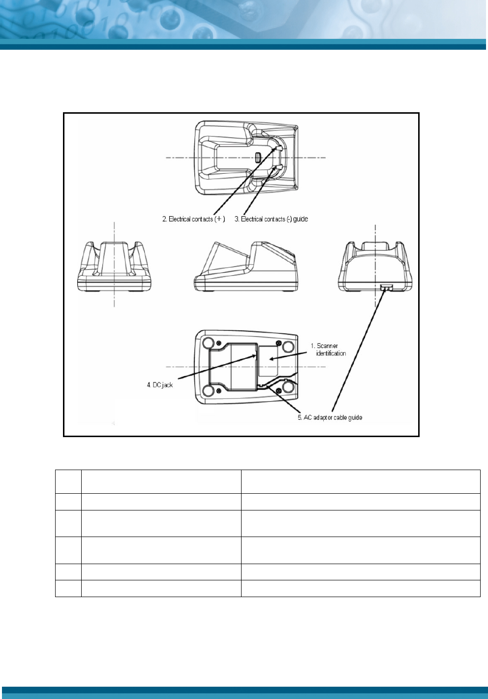
3.3. CHG 4001 (Charging Cradle for OPI 4002 Handheld Scanner)
Figure 5 and Table 3 describe the handheld scanner charging cradle and its components.
Figure 5: CHG 4001 charging cradle
ID# Name Functions
1. Scanner identification serial number Identifies product and serial number.
2. Electrical contacts (+) Positive contact feed powering the electrical contacts of
the scanner.
3. Electrical contacts (-) Negative contact feed powering the electrical contacts of
the scanner.
4. DC jack Connect the dedicated AC adaptor.
5. AC adaptor cable guide Install the dedicated AC adaptor cable along the guide.
Table 3: CHG 4001 charging cradle components
3.3.1. Battery Charging Time
The scanner battery must be fully charged before use. A completely discharged
battery can be fully recharged in approximately three hours.
Opticon
OPI 4002
Instruction Manual
14
4. Battery Pack
By default, the scanner is in Power Saving mode. To power on the unit, press the trigger key
for a few seconds. If the scanner is not in use for a while, it will go into sleep mode and the
trigger key must be pressed for a few seconds before scanning to reactivate the unit.
To fully charge the main battery, connect the dedicated AC adapter or plug the scanner into the
charging cradle.
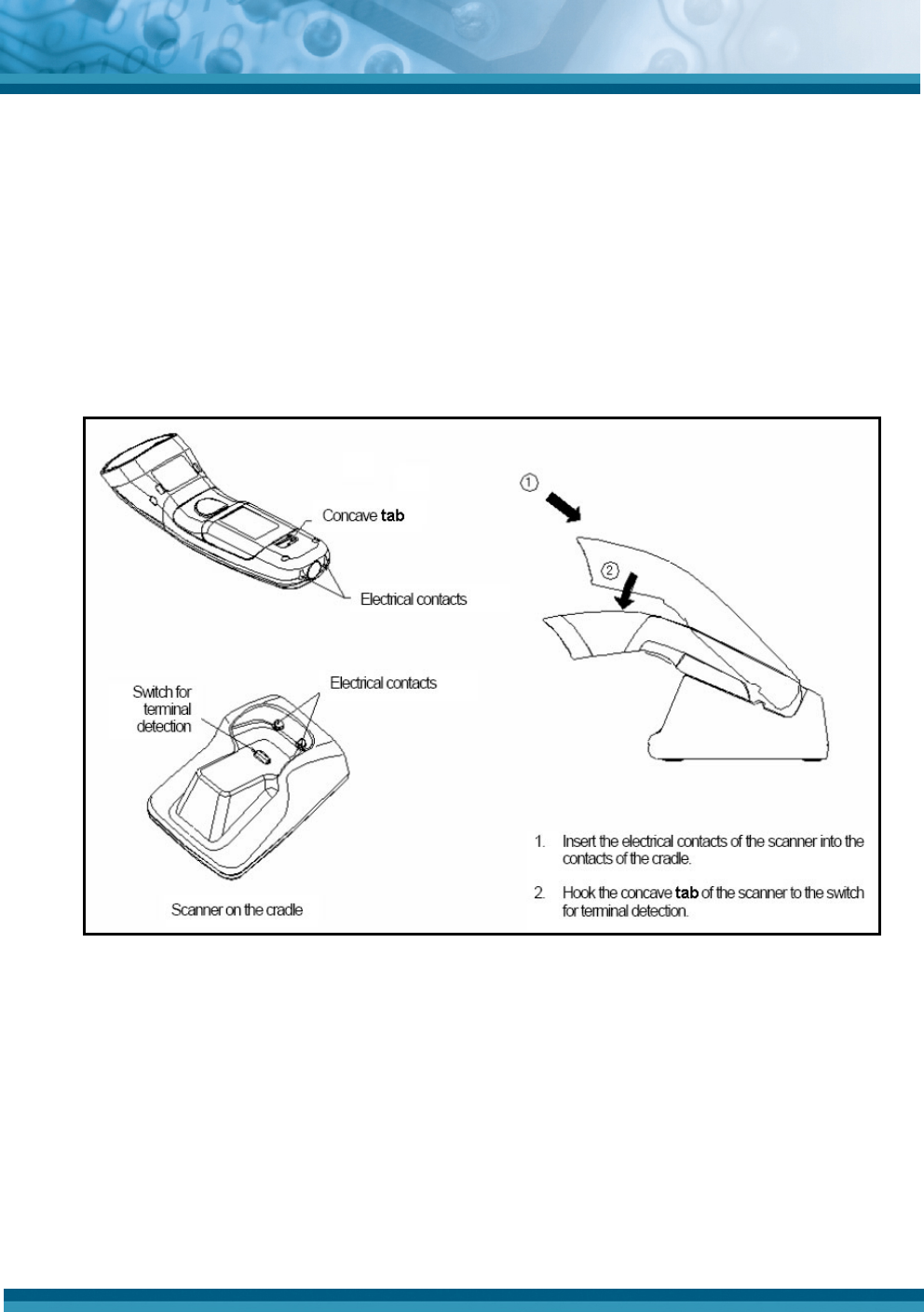
4.1. Using the Charging Cradle
Figure 6 shows the procedure for inserting the OPI 4002 handheld scanner into the CHG
4001 charging cradle.
Figure 6: Inserting the scanner into the charging cradle
Opticon
OPI 4002
Instruction Manual
15
4.2. Scanner LED Indicator State
Table 4 lists the state of the scanner based on the scanner LED.
Color Indication Description
Green Good Read A barcode was successfully decoded.
Red Blinking->Transmission
error There was a data transmission error to USB dongle.
Red Charging During charging on the cradle.
Green Green -> Red Changing color from green to red when the battery is full charged.
Red Blinking Battery voltage drop when pressing the trigger key and charging is
needed. Cannot read any barcodes.
Table 4: Scanner status—LED indicator state
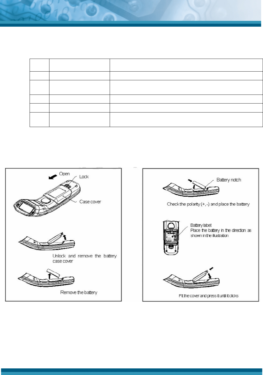
4.3. Replacing the Handheld Scanner Battery
Figure 7 shows the procedure for removing and replacing the battery, which is located in
the handle of the handheld scanner.
Figure 7: Replacing the scanner battery
The illustration on the left contains the procedure from removing the cover and then the
battery itself. The illustration on the right shows the process in reverse.

Opticon
OPI 4002
Instruction Manual
16
5. Wireless Connection
The interface used by the OPI 4002 Handheld Scanner and the OPA 1001 USB Dongle
complies with the wireless communication standard IEEE 802.15.4. The dongle is a receiver for
the scanner.
5.1. Wireless Specification
• Connection: USB Dongle: 1, Scanner: 1
• Connection Mode: Address recognition (perform the communication by
recognizing registered address)
• Encryption: Supports the 128-bit Advanced Encryption Standard (AES). AES (also
known as Rijndael) is a block cipher adopted as an encryption standard by the
U.S. government. The U.S. National Security Council adopted AES in 2002 as a
standard to transmit encrypted sensitive information.
• Distance: Approximately 30 m (depends on environment)
5.2. Settings via Menu Barcodes
The wireless connection can be configured by reading the barcodes listed in this
document, beginning on page 23.
• Register the scanner with the host computer by scanning the IEEE address
barcode label on the USB dongle (see 5.4.2 Connecting the Scanner on page 17).
• Wireless channel settings (set the communication channel of the scanner and
dongle)
• Communication control settings
5.3. Memorizing Settings
The scanner can temporarily memorize barcode data in case the scanner loses its
connection, such as when it is out of communication range. The maximum available
memory is 100 KB.
Note: This is an optional setting and is disabled by default.
When the scanner is connected again, the temporarily stored data is automatically
transmitted to the computer.
• Automatic data transmission is performed in a random period between 1.0 to 2.0
seconds.
• All memorized data is deleted if the Clear All Memorized Data (+-MCLR-+)
barcode label is read or if the wireless address is changed during data
transmission with connection loss (Orange LED blinking).
Note: If reading the Data Memorizing Disabled label, the barcode cannot be read if the
connection is lost.
Note: If reading the Data Memorizing Enabled label, a beep goes off when memory is full
and the barcode cannot be read any more. When the scanner is connected again, the
memorized data is automatically transmitted to the computer.

Opticon
OPI 4002
Instruction Manual
17
5.4. USB Dongle
The USB dongle (OPA 1001) acts as an HID keyboard interface and is supported on
Microsoft Windows 2000 through Vista.
5.4.1. Installing the Dongle
Connect the USB dongle to the host computer directly or through a commercially
available extension cable.
The Windows standard HID device driver is installed automatically when
connecting the USB dongle to the host computer’s USB port.
During initialization, the LED turns orange. The dongle LED turns green after it is
initialized and a connection is made.
5.4.2. Connecting the Scanner
1. Connect the USB dongle to the host computer and make sure a green LED is
blinking.
2. Press the trigger key to start the reading operation.
3. Scan the IEEE address barcode label “A4xxxxxxxx” on the USB dongle to
register the scanner. The connection is complete and you can start barcode
reading.
6. Scanning a Barcode
1. Remove the scanner from its cradle (if it is docked).
2. Press the trigger switch. The scanner's LED emits a beam of light to start the scanning.
Note: If the scanner is not charged or the battery's charge is low, the scanner will not
function.
3. Aim the light beam at the target barcode.
4. The scanner will beep if the scan has been successful. The OPI 4001 Handheld Scanner
will not beep if it does not scan a barcode and the light beam will turn off after 3 seconds
of pressing the trigger.
Note: The aiming pattern does not indicate an exact scannable width or distance
between a scanner and a barcode.
Opticon
OPI 4002
Instruction Manual
18
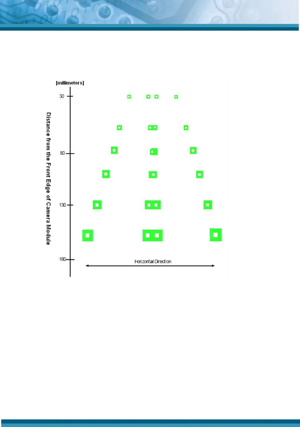
6.1. Aiming Guide
The following chart is an aiming guide that approximates the conditions for achieving a
proper scan.
Figure 8: Aiming guide for barcode scanning
A recommended aiming point is where two LED light patterns (green square-shaped symbols
on the chart) overlap or are positioned together.

Opticon
OPI 4002
Instruction Manual
19
6.2. Using the Aiming Guide to Scan
1. To scan a barcode within an aiming range:
• Make sure that two central LED light patterns overlap each other on the chart.
• Locate the center of the overlapped LED light pattern on the center of the
barcode to scan.
2. To scan a barcode wider than an aiming range:
• Aim the barcode from farther away.
• Make sure that the barcode is between two LED light patterns at right and left
ends.
Note: Due to specular reflection (mirror-like reflection of light), scanning performance
may differ depending on the media on which the target barcode is printed. Angle the
scanner to about 15 degrees if you have difficulties in scanning due to specular
reflection.

Opticon
OPI 4002
Instruction Manual
20
7. Appendix A: Default Settings
7.1. Default Settings 1: Readable Codes
Refer to the Product Specification Manual and the Universal Menu Book for readable
barcodes. Table 5 shows a list of default readable codes.
Code type Reading Transmit
Code
Length
Transmit
CD Calculate
CD Transmit
Other Prefix
Settings Suffix
Settings
UPC-A X CR
UPC-A Add-on X X CR
UPC-E X X CR
UPC-E Add-on X X CR
EAN-13 X CR
EAN-13 Add-on X X CR
EAN-8 X CR
EAN-8 Add-on X X CR
Aztec Code X X CR
Aztec Runes X X X CR
Code39 X X Not
transmit
ST/SP
CR
Code93 X CR
Code128 X CR
Data Matrix (ECC200) X X CR
Data Matrix (ECC0-140) X X CR
IATA X CR
Industrial 2of5 X X
CR
Interleaved 2of5 X X
CR
Maxi Code X X CR
Micro PDF417 X X CR
PDF417 X X CR
MSI/Plessey X CR
NW-7 (Codabar) X X Not
transmit
ST/SP
CR
QR CODE X X CR
RSS-14
Standard
Truncated

Opticon
OPI 4002
Instruction Manual
21
Code type Reading Transmit
Code
Length
Transmit
CD Calculate
CD Transmit
Other Prefix
Settings Suffix
Settings
Stacked
Stacked
Omni-
directional
X X CR
RSS Limited X X X
Standard
Stacked
RSS
Expanded
EAN-13
CCB
X
X
CR
EAN-13
CCA
EAN-13
CCB
EAN-8 CCA
Composite
EAN
EAN-8 CCB
UPC-E CCA
UPC-E CCB
UPC-A CCA
Composite
UPC UPC-A CCB
X
X
X
CR
RSS-14
CCA
RSS-14
CCB
RSS Limited
CCA
RSS Limited
CCB
RSS
Expanded
CCA
Composite
RSS
RSS
Expanded
CCB
X
X
X
CR
UCC/EAN-
128 CCA
UCC/EAN-
128 CCB
Composite
UCC/EAN
-128
UCC/EAN-
128 CCC
X
X
X
CR
Table 5: Default settings: readable codes

Opticon
OPI 4002
Instruction Manual
22
Notes:
1) In the Reading column, “” means Enable Reading and “X” means Disable Reading.
2) In the Transmit Code Length column, “” means Transmit Code Length and “X” means
“Do Not Transmit Code Length.
3) In the Transmit CD column, “” means Transmit Check Digit and “X” means Do Not
Transmit Check Digit.
4) In the Calculate CD column, “” means Calculate Check Digit and “X” means Do Not
Calculate Check Digit.
5) In the Prefix Settings column, “” means No Prefix Setting.
7.2. Default Settings 2: Read Options, Trigger, Buzzer
Item Default settings
Setting the number of characters Fixed length OFF all codes
Read mode Multiple read
Inter-character gap check (NW-7) Character *1 > Inter-character gap
Multiple columns read (barcode only)
Disabled
Trigger switch Enabled
Read time 2 seconds
Buzzer durations 200 ms
Table 6: Defaults: Settings, non-communications related
7.3. Default Settings 3: Communication Settings
Item Default settings
IEEE address Disabled
Wireless channel CH15
Encryption Enabled
Memorizing Disabled
Table 7: Defaults: Settings, communications related
Opticon
OPI 4002
Instruction Manual
23
8. Appendix B: Menu Barcodes
This section contains the menu barcode labels for the OPI 4002 default settings. Other menu
labels, such as Code Options, String Options, Read Options, and Indicator Options are listed in
the Universal Menu Book. Refer to this guide when programming the scanner for optimal
performance.
8.1. Setting Methods
There are two ways to set the required options: by scanning a Code39 barcode or by
scanning a QR code.
8.1.1. Scanning Code39 Barcodes
To set the required options:
• Scan the Set label.
• Scan the required label.
• Scan the End label in sequence. If several labels in the same option are read,
the last label read is enabled.
8.1.2. Scanning a QR Code
Scan the QR code label directly without reading the Set and End labels.
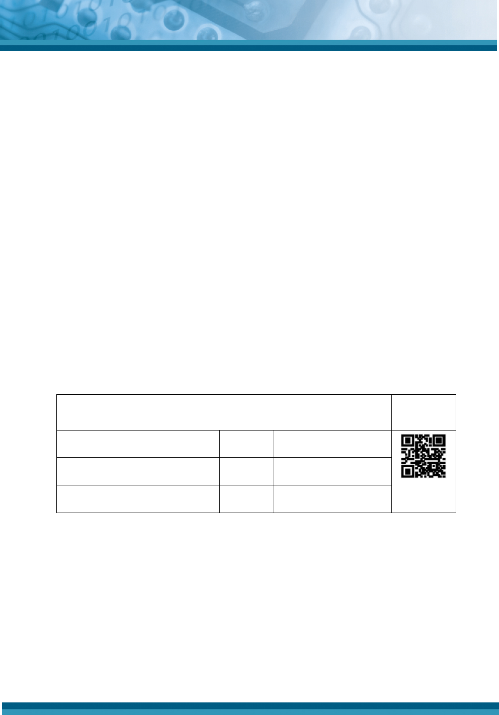
8.2. Default (Interface) Code Labels
Encryption is enabled by default.
CODE39 labels QR code
label
SET ZZ
_ZZ_
IEEE802.15.4 HID C02 _C02_
END ZZ
_ZZ_
Table 8: Default (interface) code labels list
Opticon
OPI 4002
Instruction Manual
24
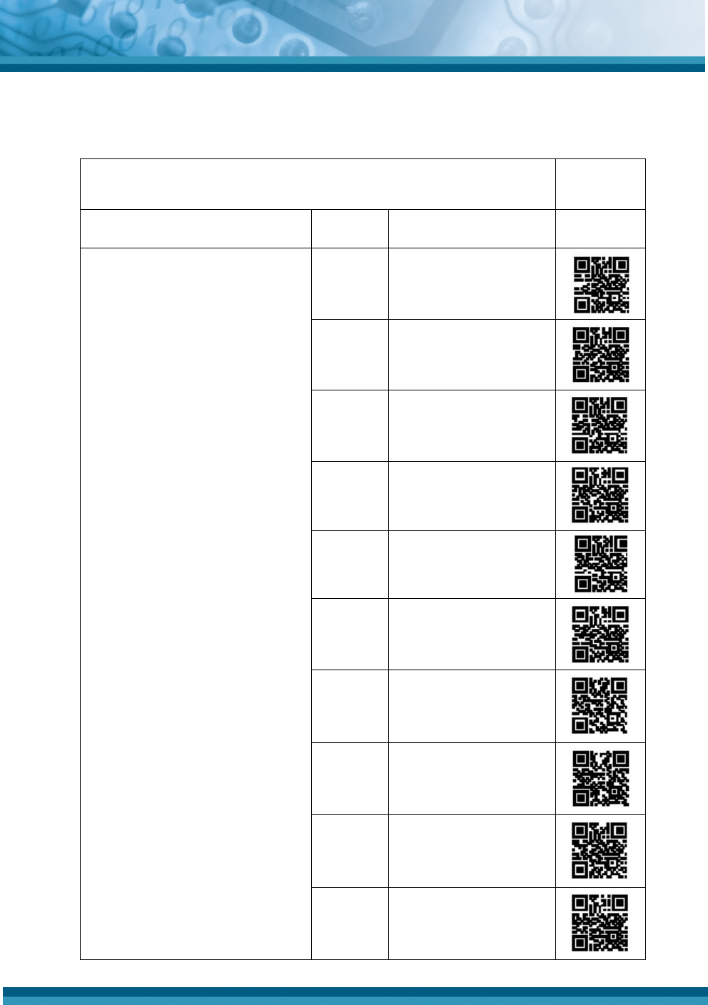
8.3. Changing the Wireless Communication Channel
Use the following barcodes to change the wireless communication channel.
Code39 labels QR code
labels
SET ZZ
_ZZ_ -
CH11 _CH11_
CH12 _CH12_
CH13 _CH13_
CH14 _CH14_
CH15 _CH15_
CH16 _CH16_
CH17 _CH17_
CH18 _CH18_
CH19 _CH19_
Communication channels
* Alternative
(Factory default setting is printed in
bold)
CH20 _CH20_

Opticon
OPI 4002
Instruction Manual
25
Code39 labels QR code
labels
CH21 _CH21_
CH22 _CH22_
CH23 _CH23_
CH24 _CH24_
CH25 _CH25_
CH26 _CH26_
END ZZ
_ZZ_ -
Table 9: Wireless communication channel barcodes

Opticon
OPI 4002
Instruction Manual
26
8.4. Memorizing Options
Code39 labelsQR code
labels
SET ZZ
_ZZ_ -
DTME Enabled _DTME_
Memorizing
(Factory default setting is
printed in bold) DTMD Disabled _DTMD_
END ZZ
_ZZ_ -
Table 10: Memorizing options code labels
8.5. Clear All Memorized Data
Clear all memorized data (ID
barcode only) _+-MCLR-+_ +-MCLR-+
Table 11: Clear All Memorized Data code labels
