Option OMO0201 GSM/GPRS/UMTS/HSDPA QUAD BAND PCI MINI CARD User Manual User Guide
Option NV GSM/GPRS/UMTS/HSDPA QUAD BAND PCI MINI CARD User Guide
UserManual.wiki
>
Option
>
OMO0201 User Manual
>
User Guide
Contents
1.
User Manual Quick Start Guide I
2.
User Manual Quick Start Guide II
3.
Safety Manual
4.
User Guide
5.
User Manual Software
6.
Annex to User Manual FCC Statements
User Guide
Navigation menu
Upload a User Manual
Namespaces
Wiki Guide
HTML
PDF
Info
Views
User Manual
Discussion / Help
Navigation
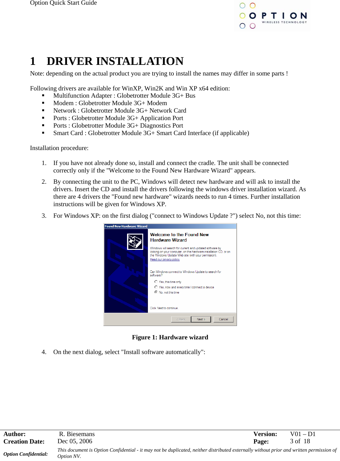
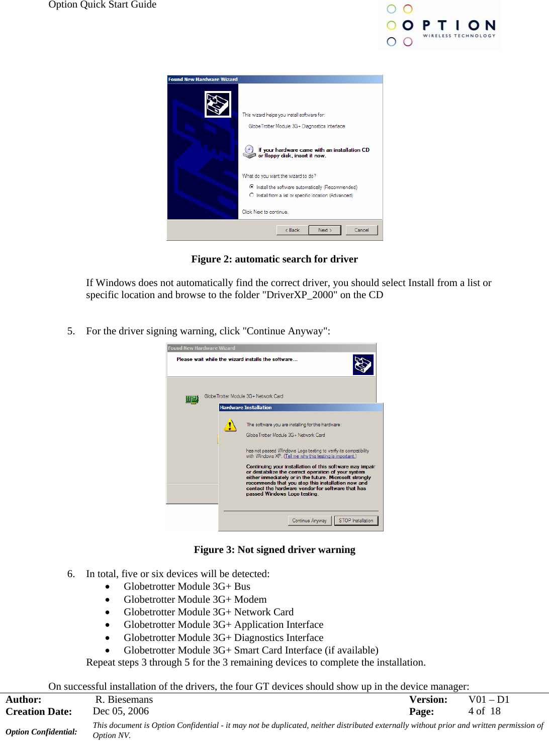
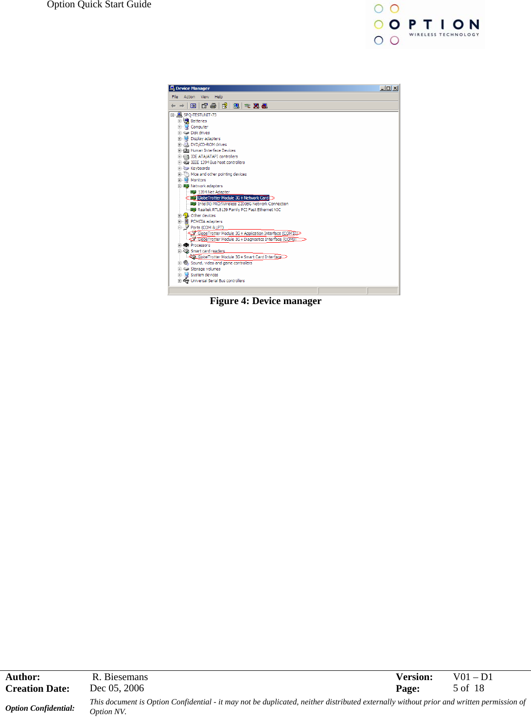
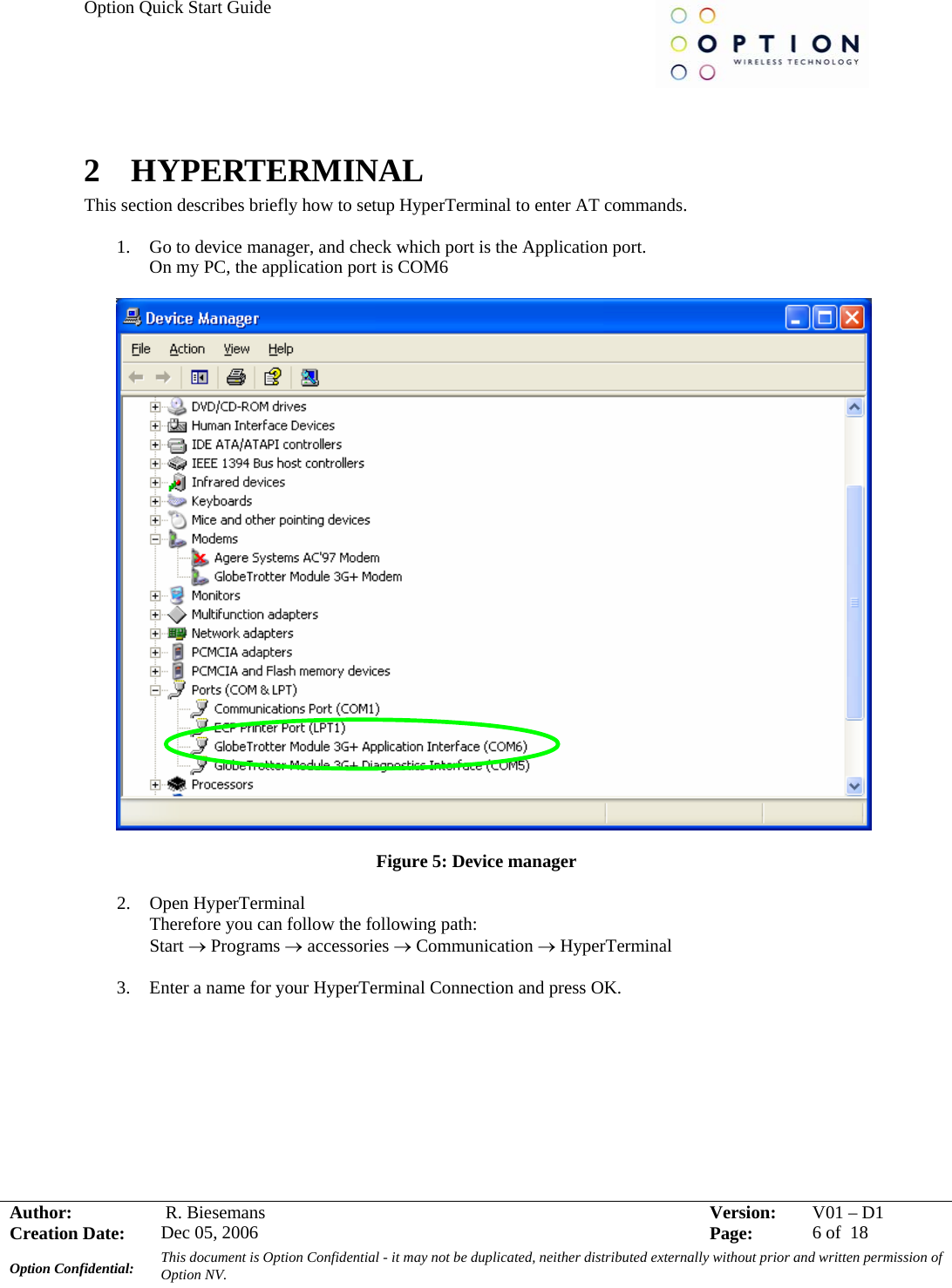
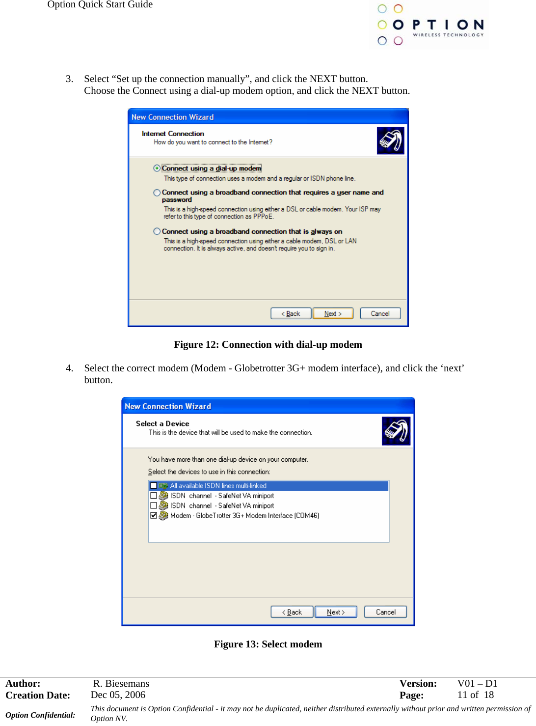
![Option Quick Start Guide Author: R. Biesemans Version: V01 –D1Creation Date: Dec 05, 2006 Page: 15 of 18 Option Confidential: This document is Option Confidential - it may not be duplicated, neither distributed externally without prior and written permission of Option NV. 4 SET UP A VOICE CALL Voice calls can be set up using HyperTerminal. In chapter 2 a description is given how HyperTerminal can be configured. Here the necessary AT commands are specified to make a voice call. 1. AT_ODO=0 With this AT command circuit switched data transfer, which is needed for voice calls, is enabled The response on this AT command should be: OK 2. AT_OPCMENABLE=1 As a default the voice part of the firmware is disabled. To enable digital voice, the command above must be set. The response on this AT command should be: OK 3. AT_OPCMCONFIG=0,0,0,256,0,1,4 When this AT command is entered, the PCM voice codec on the module/datacard is configured correctly. The response on this AT command should be: OK 4. ATD<phone number>; To set up the call, the ATD command followed by a phone number must be used. NOTE: Do not forget the semi don (;) at the end of the AT command!!! The response on this AT command should be: OK 5 WHEN CARD DOESN’T REGISTER When the module/datacard doesn’t register, you can try to evaluate following settings: 1. At_opbm When not working in a shielded environment, all life networks could interfere with the signal coming from the CMU. When the simulated network is not in the same band as the surrounding life networks, this problem can be avoided by deselecting all other basebands but the one you are working in. This could be done using the at_opbm command: Extract from datasheet: Preferred Band Mode _OPBM Command Possible response(s) _OPBM=<band>,<n> OK _ OPBM =? _OPBM: (list of supported <band>s) _ OPBM? <band>: <n>[<CR><LF><band>: <n>[…]] Description This command is used to disable/enable specific frequency bands.](https://usermanual.wiki/Option/OMO0201.User-Guide/User-Guide-1014364-Page-16.png)
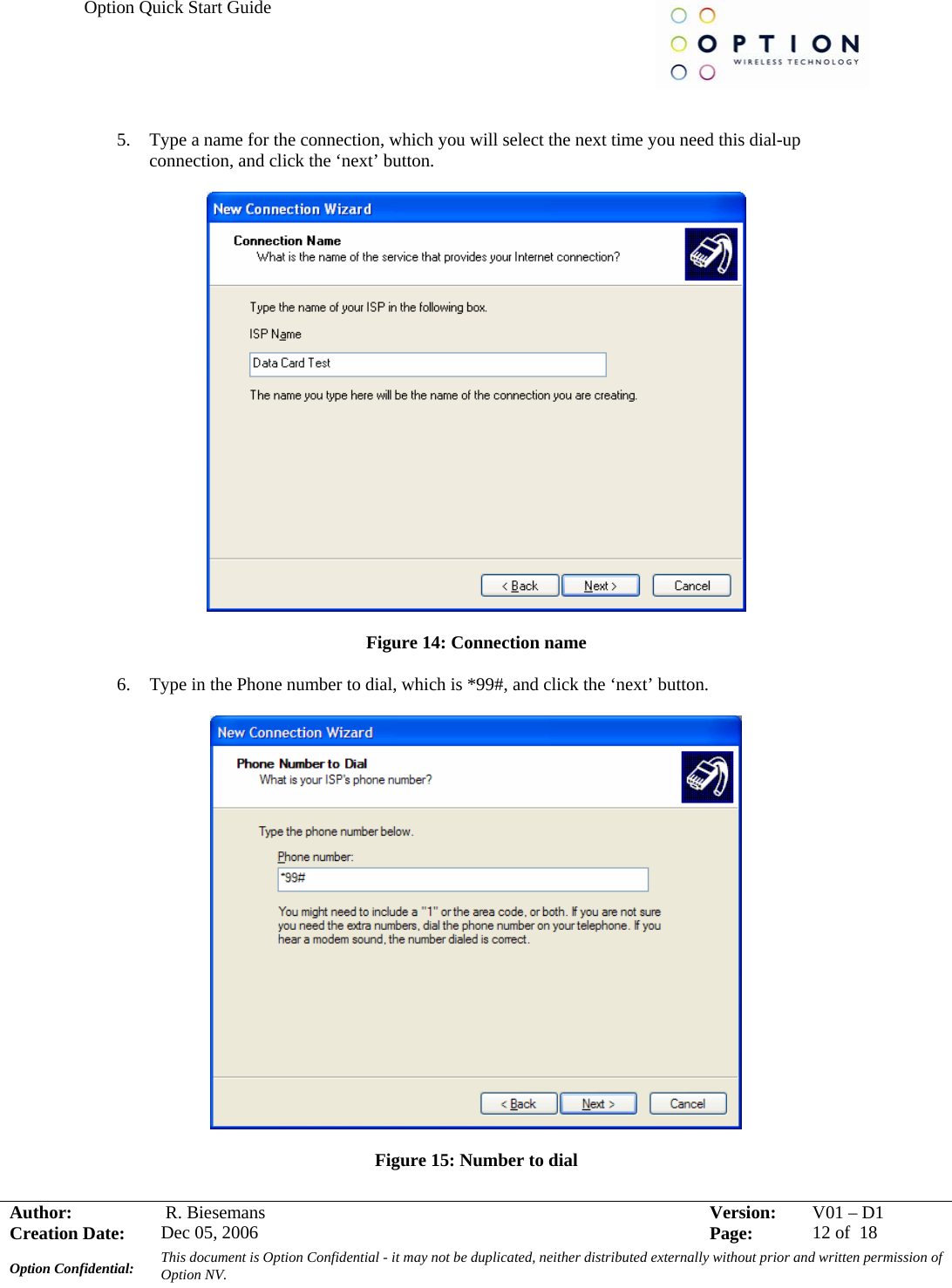
![Option Quick Start Guide Author: R. Biesemans Version: V01 –D1Creation Date: Dec 05, 2006 Page: 16 of 18 Option Confidential: This document is Option Confidential - it may not be duplicated, neither distributed externally without prior and written permission of Option NV. Defined Values <band> “ANY” : any band “EGSM” : EGSM (900MHz) band ”DCS” : DCS (1800MHz) band ”PCS” : PCS (1900MHz) band ”G850” : GSM 850MHz band ”U2100” : WCDMA 2100MHz band ”U1900” : WCDMA 1900MHz band “U1700” “U17IV” “U850” : WCDMA 1900MHz band <n> 0 : disable 1 : enable Eg: if you use GSM1900 (PCS) band, select only this band. All other bands have to be deselected. It is also very important to deselect EVERY UMTS band when trying to connect to a GSM network and vice versa: At_opbm = “PCS”,1 (selection of PCS band) At_opbm = “DCS”,0 (deselection of DCS band) Same for the other bands, also the UMTS bands!!! To check if the band is really (de)selected, use “at_opbm?” The bands showing 0 are deselected, the bands showing 1 are selected. 2. AT_OPSYS When the band settings did not work, try the OPSYS command: this command selects the UTRAN and the packet and/or circuit switched domain. Extract from datasheet: Preferred SYStem “AT_OPSYS” Command Possible Response(s) _OPSYS=[<mode>[,<domain>]] OK _OPSYS? _OPSYS: <mode>,<domain> _OPSYS=? _OPSYS: (0-5),(0-6) Description This command changes the preferred system, GSM/WCDMA, the acquisition order and the service domain preference PS/CS. Defined values](https://usermanual.wiki/Option/OMO0201.User-Guide/User-Guide-1014364-Page-17.png)
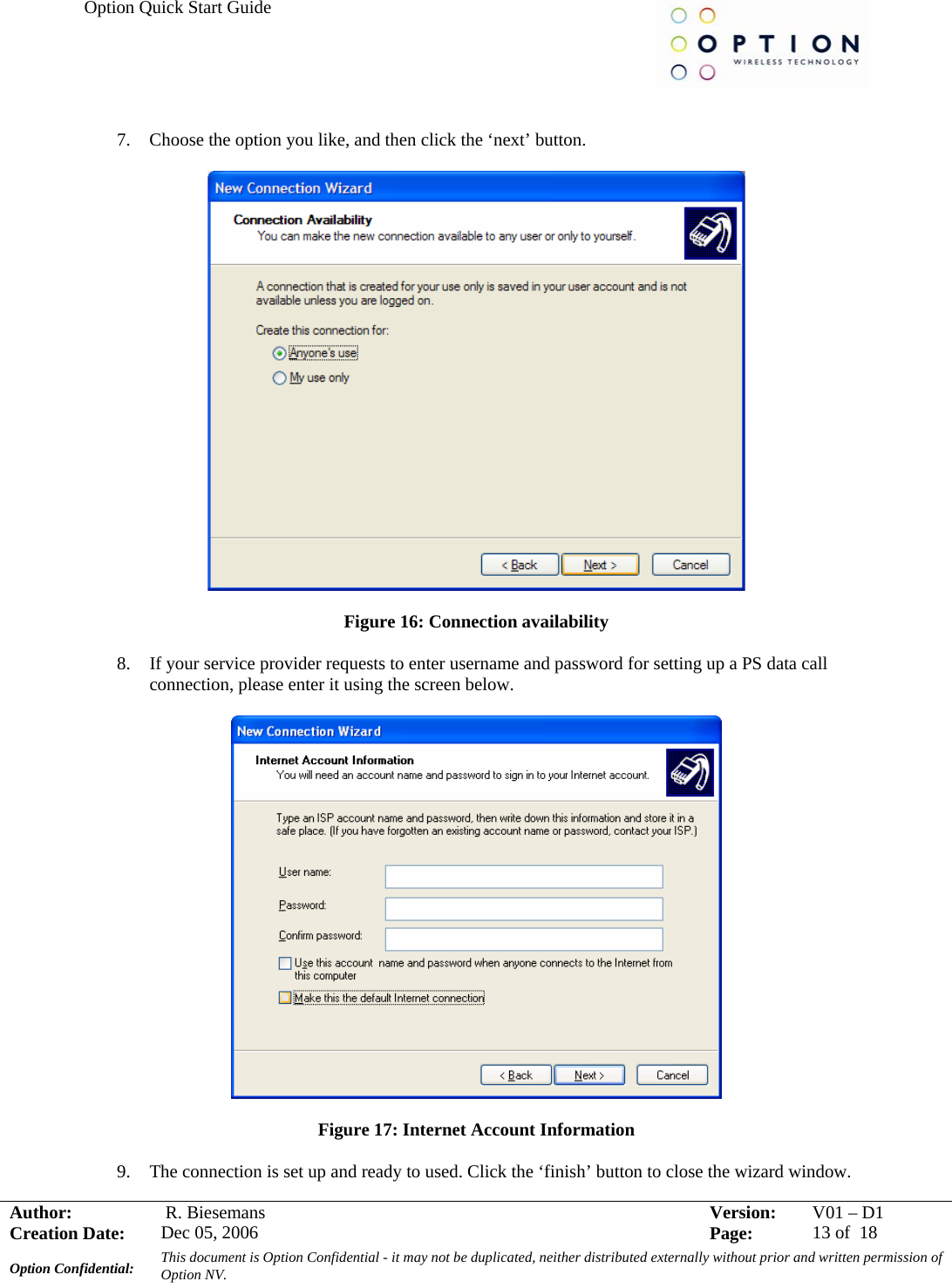
![Option Quick Start Guide Author: R. Biesemans Version: V01 –D1Creation Date: Dec 05, 2006 Page: 17 of 18 Option Confidential: This document is Option Confidential - it may not be duplicated, neither distributed externally without prior and written permission of Option NV. <mode>: 0 GSM only 1 WDMA only 2 GSM first 3 WCDMA first 4 No change 5 Auto <domain>: 0 Acquire only circuit-switched systems 1 Acquire only packet-switched systems 2 Acquire circuit-and/or packet-switched systems 3 Any domain will do; no preference Eg: at_opsys=0,2 selects options: GSM only and CS & PS domains 6 ADDITONAL AT COMMANDS This section contains some basic at commands you may need when using our datacard/modules. 1. at_osec This command sets the RRC security setting. Please note that a hard reset of the card is required before the setting will take effect. Extract from datasheet: SECurity “AT_OSEC” Command Possible Response(s) _OSEC=[<sec>] OK _OSEC? _OSEC: <sec> _OSEC=? _OSEC: (list of supported <sec>s) Description This command sets the RRC security setting. Please note that a hard reset of the card is required before the setting will take effect. Defined values <sec>: 0 None 1 Integrity](https://usermanual.wiki/Option/OMO0201.User-Guide/User-Guide-1014364-Page-18.png)