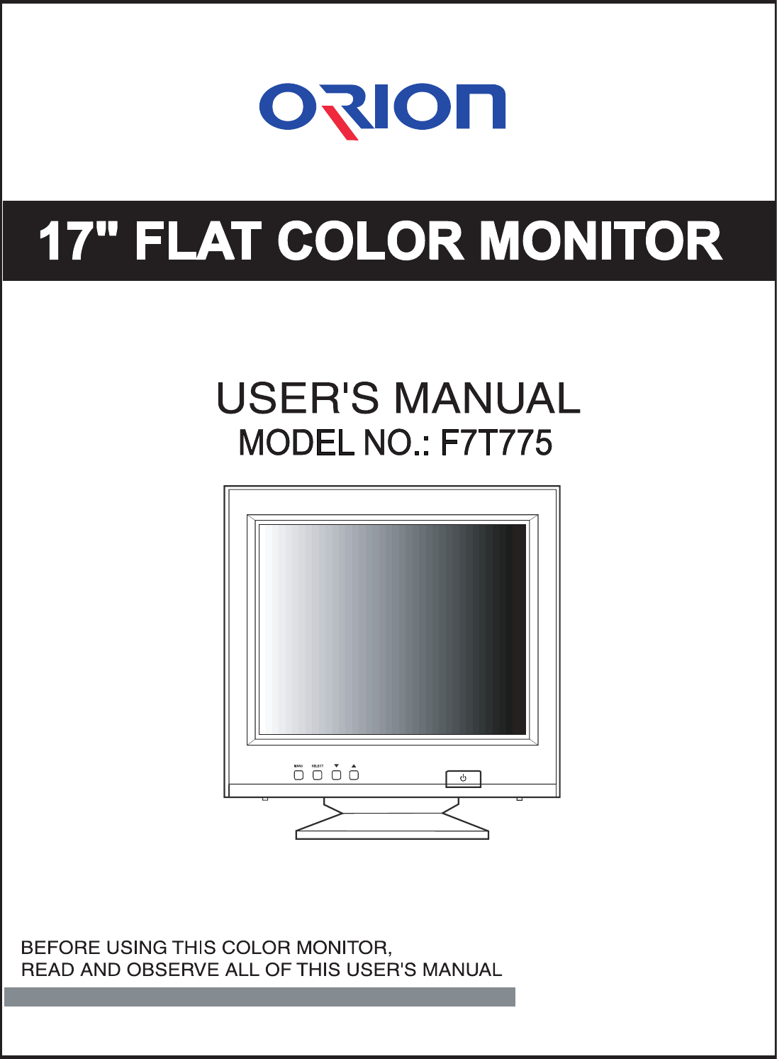
Orion Electric Co F7T775 Color Monitor User Manual

Orion Electric Co Ltd Color Monitor

User Manual

1  INSTRUCTION  MANUALCONTENTSSAFETY INSTRUCTION 2                  CAUTIONS 4                  FCC RF INTERFERENCE STATEMENT 5                  INSTALLATION 6                  RESOLUTION 7                  CONTROLS AND FUNCTIONS 8                  REAR VIEW 13                SPECIFICATIONS 14               TROUBLE SHOOTING GUIDE 15            WICHTIGE HINWEISE (GERMAN) 16              This Monitor wasManufactured by ISO 9001Certified Factory
INSTRUCTION  MANUAL 2SAFETY INSTRUCTION1. Read all of these instructions.2. Save these instructions for later use.3. Follow all warnings and instructions marked on the product.4. Unplug this product from the wall outlet before cleaning.Do not use liquid cleaners or aerosol cleaners. Use a dry cloth for cleaning.5. Do not use this product near water.6. Do not place this product on an unstable cart, stand or table.The product may fall, causing serious damage to the product.7. Slots and openings in the cabinet and the back or bottom are provided forventilation: to ensure reliable operation of the product and to protect it fromoverheating these openings must not be blocked by placing the product on a bed,sofa, rug or other similar surface. This product should not be placed near or overa heat register.This product should not be placed in a built-in installation unless proper ventilationis provided.8. This product should be operated from the type of power source indicated on themarking label. If you are not sure of the type of power available, consult your dealeror local power company.9. This product is equipped with a 3 wire grounding type plug having a third(grounding)pin. This is a safety feature. If you are unable to insert the plug into the outlet,contact your electrician to replace your obsolete outlet. Do not defeat the purpose ofthe grounding-type plug.10. Do not allow anything to rest on the power cord.Do not locate this product where persons will walk on the cord.11. If an extension cord is used with this product, make sure that the total of theampere ratings on the products plugged into the extension cord do not exceed theextension cord ampere rating. Also, make sure that the total of all productsplugged into the wall outlet does not exceed 10 amperes.12. Never push objects of any kind into this product through cabinet slots as they maytouch dangerous voltage points or short out parts that could result in a risk of fireor electric shock. Never spill any kind of liquid on the product.
3  INSTRUCTION  MANUALSAFETY INSTRUCTIONCAUTION TO SERVICE PERSONNELPOWER SUPPLY CORD IS USED AS MAIN POWER DISCONNECT DEVICE INTHIS PRODUCT. UNPLUG THIS PRODUCT FROM THE WALL OUTLETBEFORE REMOVING THE BACK COVER AND SERVICINGEMISSION CHARACTERISTICS TESTED BY SEMKOTHIS PRODUCT HAS BEEN TESTED AND HAS SHOWN COMPLIANCE WITHTHE NATIONAL SPECIFICATIONS SUCH AS SWEDISH MPR 1990.10.(MPR )13. Do not attempt to service this product yourself, as opening or removing coversmay expose you to dangerous voltage points or other risks.Refer all servicing to service personnel.14. Unplug this product from the wall outlet and refer servicing to qualified servicepersonnel under the following conditions.A. When the power cord or plug is damaged or frayed.B. If liquid has been spilled into the product.C. If the product has been exposed to rain or water.D. If the Product does not operate normally when the operating instructions arefollowed. Adjust only those controls that are covered by the operatinginstructions since improper adjustment of other controls may result in damageand will often require extensive work by a qualified technician to restore normaloperation.E. If the product has been dropped or the cabinet has been damaged.F. If the product exhibits a distinct change in performance, indicating a need forservice.CCCCAAAAUUUUTTTTIIIIOOOONNNNThe power supply cord is used as the main disconnect device, ensure that thesocket-outlet is located/installed near the equipment and is easily accessible.AAAATTTTTTTTEEEENNNNTTTTIIIIOOOONNNNLe cordon  d`alimentation est utillsé comme interrupteur général. La prise decourant doit être située ou installée à proximité du matériel et être faciled`accès
INSTRUCTION  MANUAL  4CAUTIONSNEVER REMOVE THE BACK COVERNEVER REMOVE THE BACK COVERRemoval of the back cover should be carried out only by qualified personnel.This display monitor contains high voltage inside.DO NOT USE IN HOSTILE ENVIRONMENTSDO NOT USE IN HOSTILE ENVIRONMENTSTo prevent shock or fire hazard. Do not expose the unit to rain or moisture.This unit is designed to be used in the office or home. Do not subject the unit tovibrations, dust of corrosive gases.KEEP IN A WELL VENTILATED PLACEKEEP IN A WELL VENTILATED PLACEVentilation holes are provided on the cabinet to prevent the temperature fromrising.Do not cover the unit or place anything on the top of unit. Ventilation holes areprovided also on the bottom of the cabinet.AVOID HEATAVOID HEATAvoid placing the unit in direct sunshine or near a heating appliance.BE CAREFUL OF MAGNETIC FIELDSBE CAREFUL OF MAGNETIC FIELDSDo not place a magnet, speaker system, floppy disc drive or anything which willgenerate magnetism near the unit, A magnetic field may cause blurred colors ordistortion of the displayed pattern.TO ELIMINATE EYE FATIGUETO ELIMINATE EYE FATIGUEDo not  use the unit against a bright back ground and where sunlight or other lightsources will shine directly on the monitor.BE CAREFUL OF HEAVY OBJECTBE CAREFUL OF HEAVY OBJECTNeither the monitor itself nor any other heavy object should rest on the power cord.Damage to a power cord can cause fire or electrical shock.
5   INSTRUCTION  MANUALFCC RFINTERFERENCE STATEMENTNNNNOOOOTTTTEEEE    ::::This equipment has been tested and found to comply with the limits for aClass B digital device, pursuant to Part 15 of the FCC Rules. These limits aredesigned to provide reasonable protection against harmful interference in aresidential installation.This equipment generates, uses and can radiate radio frequency energy and,if not installed and used in accordance with the instructions, may causeharmful interference to radio communications. However, there is no guaranteethat interference will not occur in a particular installation.If this equipment does cause harmful interference to radio or televisionreception which can be determined by turning the equipment off and on, the useris encouraged to try to correct the interference by one or more of the followingmeasures.- Reorient or relocate the receiving antenna.- Increase the separation between the equipment and receiver.- Connect the equipment into an outlet on a circuit different from that to whichthe receiver is connected.- Consult the dealer or an experienced radio, TV technician for help. - Only shielded interface cable should be used.Finally, any changes or modifications to the equipment by the user notexpressly approved by the grantee or manufacturer could void the usersauthority to operate such equipment.DOC COMPLIANCE NOTICEThis digital apparatus does not exceed the Class B limits for radio noise emissionsfrom digital apparatus set out in the radio interference regulation of CanadianDepartment of Communications.AVIS DE CONFORMATION AU MDC(DOC)Le présent appareil numérique n´émet pas de bruits radio-électriques dépassant leslimites appliqués aux appareils numériques de Class B d´après les règlements surle brouillage radio-électrique conçuent par le ministère des communications duCanada.
NO TOOLS ARE REQUIRED TO INSTALL THE MONITOR.SIMPLY FOLLOW THE INSTRUCTIONS OUTLINED IN THE FOLLOWING PAGE.1. INSTALLING THE TILT/SWIVEL STAND1) Align the stand with the front slots in the bottom of the monitor and insert theTilt/Swivel Stand into the slots.2) Push the Tilt/Swivel Stand firmly toward the front of the monitor until the latchesclick into the locked position.2. CONNECT THE SIGNAL CABLE1) Connect the end into the graphic card on back of the computer.2) Secure the connection with the screws on the plug.3. CONNECT THE POWER CORDConnect the female end of the power cord to the power inputreceptacle on the back panel of the monitor.Then, plug the male end of the power cord to an AC outlet or computer.4. TURN THIS MONITOR ON  AND START YOUR SYSTEMINSTRUCTION  MANUAL 6INSTALLATIONHook122
7   INSTRUCTION MANUALIt has 10 user setting modes which you can store except for factory setting mode.To display user mode except for factory setting modes, please adjust the monitor screen for yourself.After that, the screen data is stored to the memory.2. THE WAY OF ADJUSTMENTWhen you want to adjust the screen, please refer to function of controls.Those screen data are automatically stored to the memory.1. RECOMMENDED SIGNAL TIMING CHARTRESOLUTION
INSTRUCTION  MANUAL 8A. POWER ON/OFF(     )Turns the power ON or OFF.  There will be a few seconds delay beforethe display appears.The power LED(next to the power switch) lights when the poweris turned ON.The power is turned off by pressing the power switch again andthe power LED goes out.B. MENUActivates and exits the On Screen Display. This button can also beused to move previous menu or status.There are two OSD menu or status.They are MAIN MENU1 (H.POSITION, H.SIZE, V.POSITION, V.SIZE,PINCUSHION, TRAPEZOID, PARALLELOGRAM,PINBALANCE, CORNER CORRECTION, COLOR-TEMP, BRIGHTNESS, CONTRAST) MAIN MENU2 (RECALL, ROTATION, LANGUAGE, DEGAUSS,OSD H.POSITION, OSD V.POSITION, OSD ON TIME,VIDEO LEVEL, MOIRE, INFORMATION, EXIT)CONTROLS AND FUNCTIONSB. MENU BUTTOND. ADJUST BUTTONS(DOWN & UP)C. SELECT BUTTON POWER INDICATOR(LED)A. POWER SWITCH
9   INS T R UC T ION  MANUA LC ONTR OL S  AND F UNC TIONSC . S E L E C TThe select button allows user to activate the desired adjus tmentwith blinking icon.D. A DJ US T  ( ,  )The Adjust button allows us er to choose the icons (controls) in the menu.P ressing the adjust button   or  will step through all availableadjustment icons (controls ).In addition this adjust button can be used to adjust the icons (dot controls)that is s elected and activated (blinking) via the s elect button. When the adjust buttonis pres s ed, T he adjustment bar in the window will be increased or decreased.After completing all the desired adjustments, the On S creen Displaywill dis appear with pres sing the menu button.1. S E L F -TE S T DIS P L AYWhen there is no connection, the On S creen Displaywill show.MAIN ME NU 1 activates when you press the Menu button.MAIN ME NU 2 activates when you press () at the C ONT R AS T(E XIT) icon in the menu1.NO S IG NALC HE C K  S IG NAL C AB LE
INS TR UC T ION  MANUAL 10C ONTR OL S  AND FUNC TIONS2. AUTO R E G IS TR ATIONThis monitor has 10 preset modes. If the current video is one of thepreset modes, the monitor keeps storing the custom display settingsinto the permanent memory.There are also 10 user modes that allow you to save the custom displaysettings made to any video mode that is not one of the preset modes.Adjustments are automatically registered without pressing any buttons.Up to 10 user modes are stored automatically on a ÒFirst-In-First-OutÓbasis.3. OS D ME NU DE S C R IPT IONMAIN ME NU 1H. P OS ITION (Horizontal Pos ition)Moves images horizontally on screen left( ) or right( ).H. S IZE  (Horizontal S ize)Increases( ) or decreases( ) S ize of image horizontally.V. P OS ITION (Vertical P os ition)Moves images vertically on screen up( ) or down( ).V. S IZE  (Vertical S ize)Increases( ) or decreases( ) S ize of image vertically.P INC US HIONAdjusts the side P incushion or barrelling.TR AP E ZOIDAdjusts the display sides to be parallel.P AR AL L E L OG R AMAdjusts the tilt of the display sides.P INB A L ANC EAdjusts the curvature of the left and right sides of the screen image.
11  INS TR UC TION  MANUALC ONTR OL S  AND FUNC TIONSC OR NE R  C OR R E C TIONUser can select Top or B ottom C orner correction by pressingthe S elect button.TOP C OR NE R  C OR R E C TIONC orrects the top corner image shape to a  rectangle.BOTTOM C OR NE R  C OR R E C TIONC orrects the bottom corner image shape to a rectangle.C OL OR -TE MPAdjusts color temperature to 9300K, 6500K (notes : 9300K is factory default).Or, for a custom color mode, select ÒUS E R Ó and keep pressing select key approximately 2 seconds to activate the R G B  S ub-menu.This adjust the intensity of the R G B  video output. Using the select buttonactivate(blinking) the R -G AIN(R ed G ain), G -GAIN(G reen G ain) or B-G AIN(Blue G ain) and change color strength for a customized color mode.B R IG HT NE S SIncreases( ) or decreases( ) the intensity(illumination) of the image.C ONTR AS TIncreases( ) or decreases( ) the strength(lightness or dimness)of the image.MAIN ME NU 2R E C A L LR esets the control functions back to the original factory preset values.In order for the R ecall function working, the timing must fall under oneof the factory preset timing modes.R OTATIONAdjusts the tilt of image.L A NG UA G ES elects a language among E NG LIS H, DE UT S C H, F R AN‚ AIS , E S PA„ OL, ITALIANO.DE G A US SManually demagnetizes the C DT. This can be used if the displaybecomes discolored.Allow a minimum of 20 minutes to elapse between each degauss.The monitor also will automatically degauss when power is applied, and power saving mode is changed to normal mode.
OS D H.P OS ITIONMoves the OS D position to left or right.OS D V.P OS ITIONMoves the OS D position to up or down.OS D ON TIMEIf there isnÕt key pressure OS D will be disappeared automatically the setted seconds later.VIDE O L E VE LS elects the video level of the Video G raphic C ard.If the intensity of image is high select 1.0V & if low select 0.7V.MOIR EAdjusts the moire level of the screen.Activate MOIR E  icon & keep pressing select button approximately 2seconds after select ÒONÓ.H. MOIR E  ADJ US TR educes the optical effect of horizontal wavy lines on the display image.These effects are usually more noticeable on large gray areas or on black & white check board patterns.V. MOIR E  ADJ US TR educes the optical effect of vertical wavy lines on the display image. These effects are usually more noticeable on large gray areas or on black & white check board patterns.INFOR MATIONDisplays the current mode, horizontal frequency, vertical frequency,the factory preset mode and user preset mode.E XITE xit user menu.INS TR UC T ION  MANUAL 12C ONTR OL S  AND FUNC TIONS
13  INSTRUCTION  MANUALREAR VIEWE. AC INLETPower cord connection.NNOOTTEE::Power cord is used as main power disconnect device in this product.F. D-SUB CONNECTOR OF SIGNAL CABLEConnect to the analog RGB signal output connector of IBM PS/2, or compatible computer.ACCESSORY1. POWER CORD2. INSTRUCTION MANUALE. AC  INLET F. D-SUB CONNECTOROF SIGNAL CABLE
SPECIFICATIONSINSTRUCTION  MANUAL 14PICTURE TUBE17 (16V) Flat CDTDot Type 0.25mm Pitch Black Matrix Screen High resolution screenDark Faceplate Glass High contrast screen90 Deflection and 29.1mm Diameter Neck Lower power consumption16 Visual Screen Diagonal Full-square type screenAnti-Static Charge Face Electro static charge eliminatedHi-view(Silica coat, Anti-Glare, Anti-Reflection) Surface Glare problem eliminatedInvar Shadow Mask.INPUT SIGNALD-SUB INPUTAnalog RGB Video: 0.7Vpp / 75Sync.: TTL LevelSWEEP FREQUENCYHorizontal: 30-70KHz(Automatically)Vertical: 50-150Hz(Automatically)DISPLAY AREA(16 Viewable Size)Full Size: 326 x 245mmPreset Size: 305 x 225mmPOWER INPUTAC 100-240V, 50/60Hz, 1.6-0.8A (FREE VOLTAGE)POWER CONSUMPTION85Watts(Max.)Power Saving: Less than 5WDimensions (W x D x H)399mm X 411mm X 394mmWEIGHTNet Weight : 16.0Kg   Gross Weight : 18.5KgRESOLUTION1280 dots x 1024 lines(Max.)DDC 1/2BOSD(On Screen Display)NNOOTTEE  ::Technical specifications are subject to change without notice.
15  INSTRUCTION  MANUALTROUBLE SHOOTING GUIDEThe video card should be completelyseated in its slot.Power switch and computer power switch shouldbe in the ON position.The signal cable should be completely connectedto the video card/computer.Check connector for bent or pushed-in pins.Power switch should be in the ON position and thepower cord should be connected.Adjust size and position controls to adjust theimage.Wait approximately ten seconds after makingadjustments before changing or disconnection thesignal or powering OFF the monitor.Signal cable should be completely attached to thecomputer.Check the pin assignments and signal timmings ofthe monitor and your video card.Move electrical that may be causing electricalinterference away from the monitor.Adjust the side pin-cushion control.PROBLEM CHECK THESE ITEMSNo Picture(Not in power saving mode)LED on the monitor is not litDisplay image is notcentered, too small or too largeDisplay size and positionwere not savedImage is scrolling orunstablePicture bounces or a wavepattern is present inthe pictureEdges of the display imageare curved either inwardor outward
Achten Sie darauf, da das Gerät nur in eine AC100-240V Schuko-Steckdose eingesteckt wird.Die Steckdose sollte jederzeit frei zugänglich sein, um bei einem evtl.auftretenden Notfall das Gerät schnell von der Stromversorgung zu trennen.Achten Sie desweiteren darauf, da die Netzanschlu leitung nichtmechanisch beansprucht noch sonstwie beschädigt wird.Öffnen Sie niemals das Gerät!  Im Inneren befinden sich Teile mitgefährlicher Spannung.Bevor Sie das Gerät reinigen, ziehen Sie bitte den Netzstecker aus derSteckdose. Säubern Sie das Gerät dann mit einem feuchten (keinesfallstropfnassen) Lappen.Das Gerät ist funkentstört nach EN55022Bauartzulassung:Die in diesem Gerät entstehende Röntgenstrahlung ist ausreichendabgeschirmt (Ortsdosis in 0.1m Abstand weniger als 1.0 /h).Die Beschleunigungsspannung beträgt maximal 28KV.Stellen Sie das Gerät an einem ergonomisch günstigen Ort auf und sorgenSie dafür, da der Betrieb des Monitors mit nach ISO9241-3.7.8geprüfter Peripherie sichergestellt ist.Maschinenlärminformationsverordnung 3. GSGV, 18.01.91 : Derarbeitsplatzbezogene Schalldruckpegel beträgt 70dB(A) oder wenigergemä ISO 7779.Falls SIe dennoch Fragen haben, auf die Bedienungsanleitung keineAntwork geben kann, so kontaktieren Sie bitte den nächsten Fachhändler.FOR GERMAN                                                     WICHTIGE HINWEISEINSTRUCTION  MANUAL 16

Navigation menu