Orion Electric Co LV520H LV520H LED Monitor User Manual for LV520H Monitor
Orion Electric Co Ltd LV520H LED Monitor Users Manual for LV520H Monitor
UserManual.wiki
>
Orion Electric Co
>
LV520H User Manual
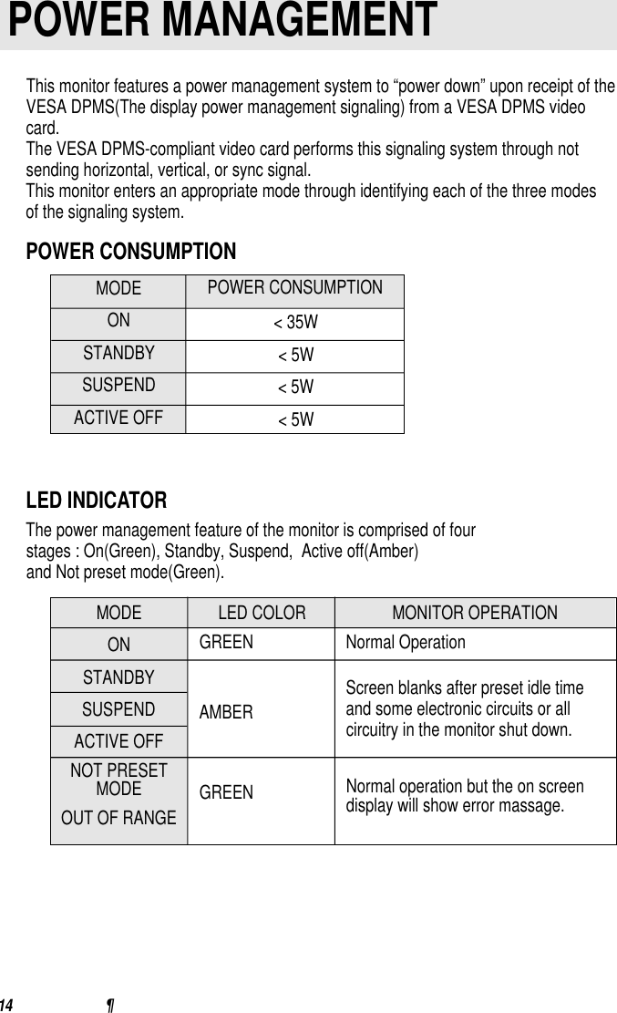
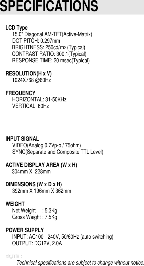
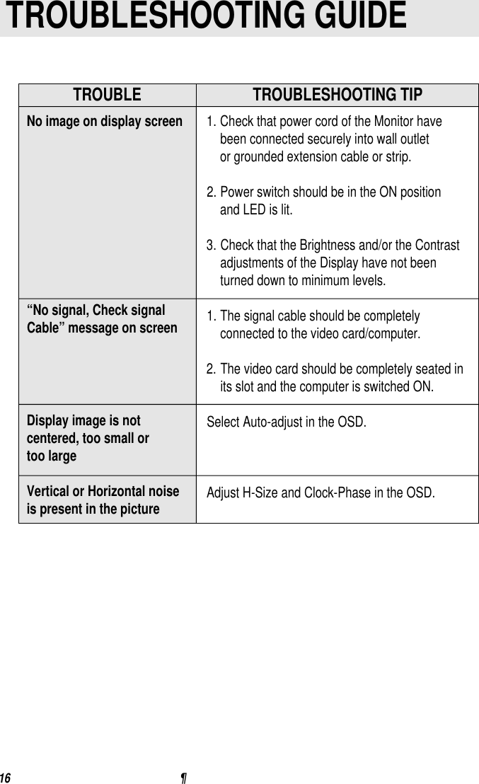
Users Manual for LV520H Monitor
Navigation menu
Upload a User Manual
Namespaces
Wiki Guide
HTML
PDF
Info
Views
User Manual
Discussion / Help
Navigation