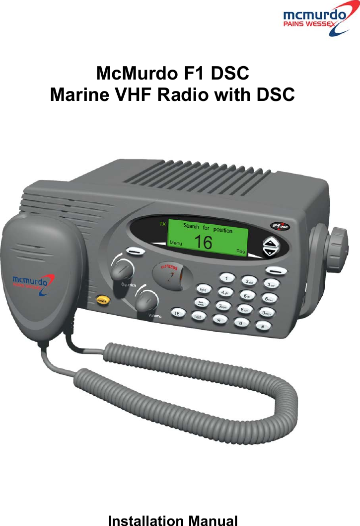
Orolia F1DSC VHF Marine radiotelephone inc.class 'D' DSC User Manual Installation
Orolia Ltd VHF Marine radiotelephone inc.class 'D' DSC Installation
UserManual.wiki
>
Orolia
>
F1DSC User Manual
>
Installation
Contents
1.
Installation
2.
Operator
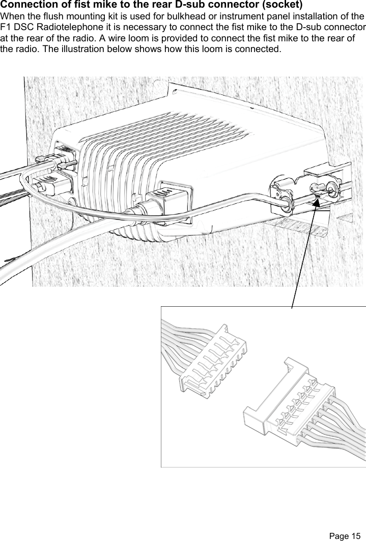
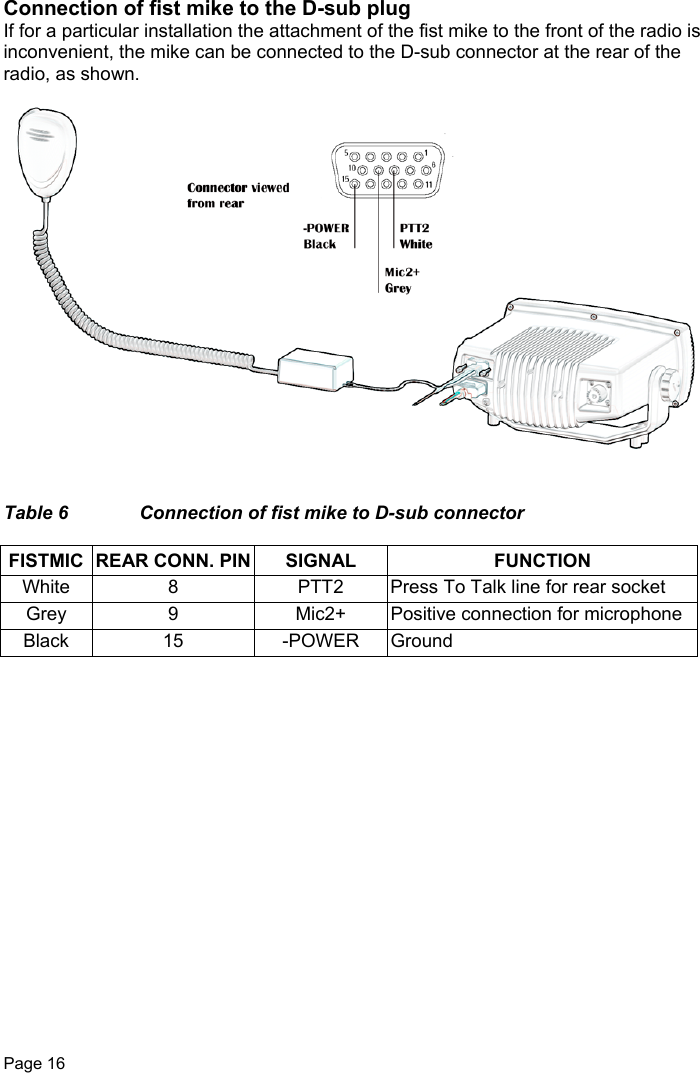
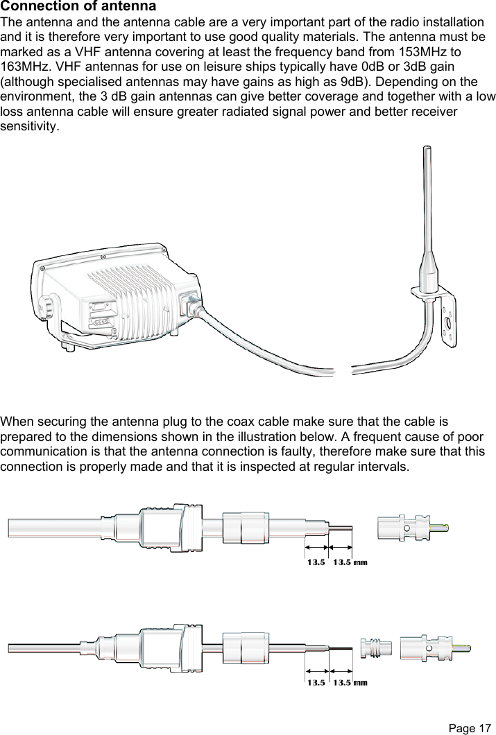
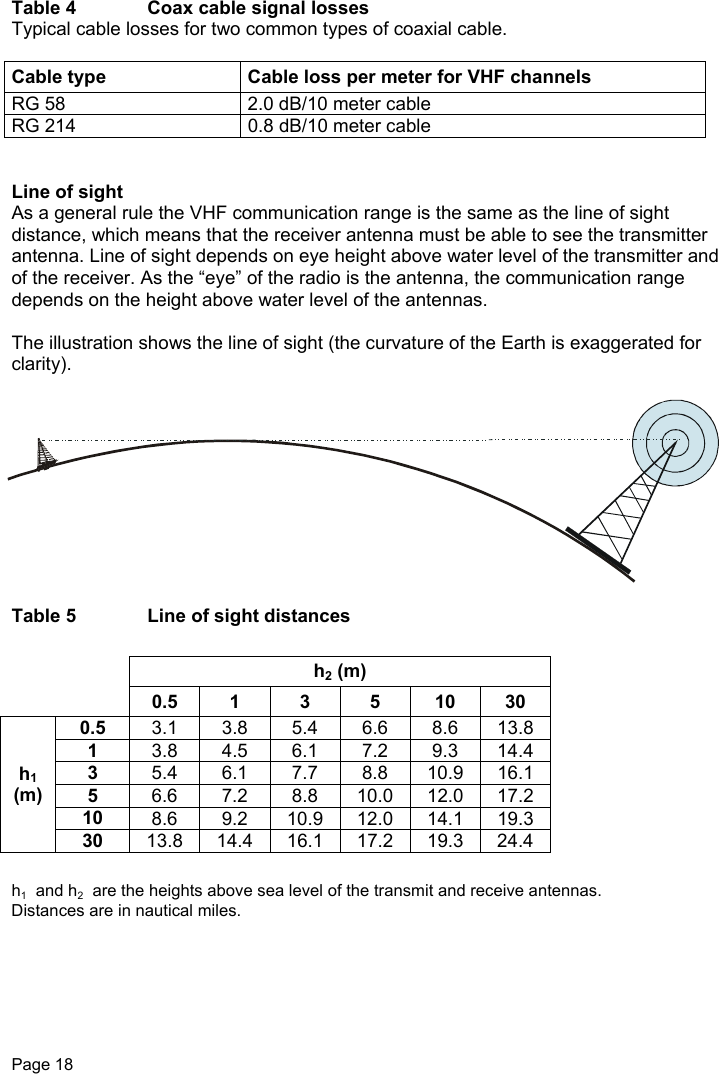
Installation
Navigation menu
Upload a User Manual
Namespaces
Wiki Guide
HTML
PDF
Info
Views
User Manual
Discussion / Help
Navigation