Orolia M-2 McMurdo Automatic Identification System User Manual Operation Manual
Orolia Ltd McMurdo Automatic Identification System Operation Manual
Orolia >
Contents
- 1. Installation Manual
- 2. Operation Manual
Operation Manual

Operation Manual
M-2 AIS Transponder System
Applicability of this manual
This manual illustrates the operation of Display model V01.02.xx
In accordance with McMurdo's policy of continual development and product
improvement, equipment may be upgraded from time to time and future
versions may therefore not correspond exactly with this manual. When
necessary, upgrades will be accompanied by updates or addenda to this
manual.
Disclaimer
Information contained in this manual is supplied in good faith, but is liable to
change without notice. McMurdo Limited disclaims any liability for
consequences arising from omissions or inaccuracies in the manuals and
documentation provided with this product.
IMPORTANT: Please take time to read this manual carefully and to understand
its contents fully, so that you can operate your Transceiver correctly.
© 2004 McMurdo Limited
Safety Summary
WARNING: ENSURE THAT THE M-2 AIS HAS BEEN CORRECTLY
INSTALLED IN ACCORDANCE WITH IMO GUIDELINES AND THE
SUPPLIED INSTALLATION MANUAL BEFORE POWERING ON THE
SYSTEM.
WARNING: The M-2 has no ON/OFF or power switch. It will automatically start
operation within 2 minutes of applying power to the transponder unit.
WARNING: Transponder chassis can become hot during extended periods of
operation. Avoid touching this when the transponder is operating. The plastic
dust cover must be fixed in place before setting the equipment to work.
WARNING: Do not touch the VHF antenna or connecting cable when the
transponder is in operation.
WARNING: Unauthorised opening of the transponder access covers may
invalidate the manufacturer’s warranty.
WARNING: Avoid using chemical solvents to clean the Display or transponder
dust cover as they can damage the casing material.
WARNING: The use and operation of an AIS transponder is legislated and
forms a part of the ship’s mandatory navigation equipment under SOLAS
regulations. It is therefore necessary that the installation is certified
(commissioned) and that certain information has to be available before full
operation of the transponder can take place. The ship’s IMO and MMSI
numbers and other important information must be entered as part of the
installation and commissioning procedure, and before the equipment is used at
sea.
WARNING: This product is sold or provided as merely an aid to navigation. It is
the responsibility of the user to exercise discretion and proper navigational and
seamanship skills.
WARNING: NOT ALL SHIPS CARRY AIS. The Officer of the Watch (OOW)
should always be aware that other ships and, in particular, leisure craft, fishing
boats and warships, and in some cases coastal shore stations (including
Vessel Traffic Systems (VTS) centres), may not be fitted with AIS. The OOW
should always be aware that AIS fitted on other ships as a mandatory carriage
requirement may, under certain circumstances, be switched off based on the
Master’s professional judgement.
WARNING: The use of a Megger (High Voltage Insulation Tester) may damage
the equipment and therefore should not be used.
WARNING: Do not operate the equipment when persons are closer than 3
metres from the antenna. If any person (e.g. the operator) must be closer, then
a grounded RF shield should be interposed between that person and the
antenna.
AIS Operation Licensing
IMPORTANT: Operation of the AIS Transponder is covered by international
radio regulations and therefore the ship must possess a valid ship’s radio
licence. The AIS equipment must be correctly registered (Call Sign and MMSI
number). Operation of AIS equipment without a valid MMSI number
contravenes international radio regulations and must be avoided. Please
contact the relevant authority in your country for further information regarding
ship’s radio licensing requirements.
Disclaimer
Information contained in this manual is correct at time of going to print but is
liable to change without notice. McMurdo Limited disclaims any liability for
consequences arising from omissions or inaccuracies in the manuals and
documentation provided with this product.
Equipment may be upgraded and features added at any time; however, the
basic principles given in this document will remain unchanged.
Contents
Introduction ...............................................................................1
Product Definition ..........................................................................2
AIS in use.....................................................................................3
M-2 Key AIS Functions ..................................................................4
M-2 Product description.................................................................5
Quick Start - setting to work .................................................7
Starting the M-2.............................................................................7
Display and controls ...............................................................8
Using Softkey menus ...................................................................10
General operation.......................................................................11
General operation........................................................................12
Password access control .............................................................14
Detailed operation..................................................................17
VOYAGE Mode: Current Status....................................................18
VOYAGE Mode: Own Voyage ......................................................19
Target Mode: Target list...............................................................21
Target Mode: Target Plot .............................................................22
Reading and sending safety messages .........................................24
Target Mode: All messages..........................................................25
Target Mode: Short messaging, Target message...........................28
Target mode: Short messaging, BROADCAST message................29
Alarm mode: All events log...........................................................30
Alarm mode: Current alarms ........................................................31
Alarm mode: Alarms log...............................................................32
Alarm mode: Security log .............................................................33
System configuration...................................................................35
Ship’s Static Data........................................................................37
Channel Regions.........................................................................39
Configuration...............................................................................42
Setup mode: long range responses ..............................................43
Maintenance and Servicing.................................................45
Troubleshooting.....................................................................46
Alarm Messages..........................................................................49
Declaration of Conformity ...................................................53
Index..........................................................................................55
M-2 AIS Operation Issue 1 1
Introduction
About this Manual
This operation m anual has been designed to help the user understand how to
operate the M-2 AIS transponder system . Before attempting operation for the
first time, please read this manual thoroughly. The first sections are an overview
of the most commonly used features and a description of the various modes of
operation; the remainder of the sections have a full explanation of all the
features and user settings.
It is assumed that the M-2 installation is complete and all appropriate external
equipment is connected and working as intended. A separate M-2 installation
manual is supplied with the equipment; this details full installation procedures
and provides routine service information.
This manual provides a step by step guide to the procedures typically required
to operate the M-2 as a Class A shipborne equipment.
It explains how to:
- Review and update own vessel static and voyage related information
- Check the current status of the AIS system and connected sensors
- List other AIS targets and view as a geographic plot overview
- View and set VHF AIS regions
- View and create safety text Messages
- Check status of alarms and view the system security log
- Respond to Long Range requests
- Troubleshoot
2 Issue 1 M-2 AIS Operation
Product Definition
AIS overview
The Automatic Identification System (AIS) system provides for communication,
navigation and s urveillance capabilities for vessels and for fixed coast radio
stations. The AIS transponder offers high-speed automated communication from
ship to ship and ship to shore of vessel-, voyage- and safety-related information.
Own vessel navigational data is automatically transmitted directly to surrounding
vessels and shore based VTS systems utilising marine VHF channels. The AIS
gives mariners the ability to vie w at a glance the status of AIS equipped vessels
and aids to navigation around them and provides access to a host of detailed
navigation information.
M-2 AIS Operation Issue 1 3
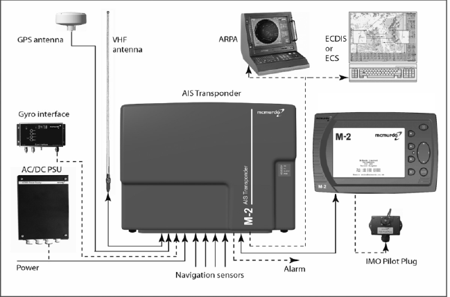
The M-2 is primarily designed for use as a shipborne AIS mobile station, and
comprises of two main parts:
Transponder
The M-2 AIS transponder has an integral Global Navigation Satellite System
(GNSS) engine used for timing, one radio transmitter, three radio receivers and
a computer unit. The AIS equipment should be interfaced to the vessel’s primary
GNSS navigation receiver, connected to a marine antenna and be interfaced to
the vessel’s gyro compass.
As appropriate to the class and use of vessel, there is provision for additional
interface connections : Rate of Turn (ROT) indicator, bottom track speed log,
differential beacon Global Positioning System (GPS) receiver, Electronic Chart
Display Information System (ECDIS) or Automatic Radar Plotting Aid (ARPA)
system, Pilot Plug and Long Range port.
Display
The Display is used to input vessel details, configure the system and to display
AIS target information.
An IMO pilot plug socket box may be attached to a socket on the rear of the
display or connected directly to the transponder.
AIS in use
The AIS Transponder transmits information which is separated into three
groups:
Static data - Vessel name, type, length and breadth, MMSI and IMO numbers
and GNSS antenna location.
Dynamic data – Position, accuracy and integrity of the position, time, course
and speed over ground and navigational status.
Voyage data – Cargo, draught, port of destination and estimated time of arrival.
In addition, the AIS can transmit and receive Safety Messages . These may
include navigation safety information, warnings of floating objects, collisions,
meteorological situations, etc.
Differential correction information for GNSS can be processed by the AIS,
increasing the accuracy of positional information and hence the safety of the
vessel. Differential correction information can also be provided by connection of
a supplementary differential beacon differential receiver.
4 Issue 1 M-2 AIS Operation
M-2 Key AIS Functions
- Automatic identification of other AIS equipped stations.
- Self-organising control of access to the radio channels.
- Reception of data from other vessels and coast radio stations.
- Transmission of own vessel data for use by other vessels and coast stations.
- Storage of static data intended for automatic transmission via the radio
channels.
- Output of data received via the radio channels from other AIS targets for
presentation on the Display or other visual display equipment.
- Determination of the position and motion of own vessel if the external GNSS
receiver fails , by utilising the internal GNSS receiver.
- Application of GNSS differential corrections using information supplied from a
supplementary differential beacon receiver.
- Application of GNSS differential corrections using information received from a
controlling station via Message 17 over the AIS VHF Data Link (VDL) channel.
- Display of bearings and distances to the vessels, calculated from their co-
ordinates, obtained via the AIS VDL channels.
Operation
Please read all the warning notices at the front of this manual before applying
power to the AIS Transponder and setting the equipment to work.
Activation
It is recommended that AIS should not normally be powered down and should
always remain in operation continuously. However, based on the Master’s
professional judgement, either transmissions may be inhibited by selecting
‘Silent mode’ or the AIS may be powered down entirely if continuous operation
might compromise the ship’s safety or security. This might be necessary in
waters where pirates or armed robbers are known to operate or during some
cargo handling or maintenance operations.
Actions of this nature should always be recorded in the ship’s logbook.
Reactivation of the AIS should take place as soon as the reason for deactivation
has passed.
Compliance
The M-2 AIS complies with international standards and is type approved in
accordance with the European Marine Equipment Directive. The EU Declaration
of Conformity, shown on the rear pages, lists the relevant approval standards .
Details of other Worldwide type approvals are listed on the McMurdo website
www.mcmurdo.co.uk

M-2 AIS Operation Issue 1 5
M-2 Product description
Key features
• Shipborne Class A AIS
• Versatile Keyboard and Display Unit
• Clear presentation of targets as graphics and text
• Integral 16 channel Space-Based Augmentation System (SBAS)
-enabled GPS receiver
• Differential GNSS (DGNSS) correction
• Interfaces to ECS, ECDIS, ARPA
• Pilot plug connection
• Integral ship’s cable termination board
• Four sensor interfaces
• Long Range port
The M-2 gives a clear indication of identity, proximity and bearing of surrounding
AIS targets. By providing this information in both graphic and text formats the
need for ‘bridge to bridge’ radio voice contact between vessels is much reduced.
AIS targets are unaffected by radar shadow effects and remain visible even
when targets may be lost to the vessel’s radar.
Own vessel static and voyage related information is broadcast automatically
every six minutes. Depending on the speed the vessel is making, dynamic
factors (speed, course, heading and rate of turn) are transmitted at intervals of
between two and twelve seconds or every three minutes when moored.
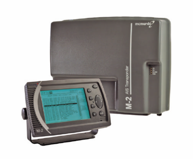
M-2 Display controller and Transponder unit
6 Issue 1 M-2 AIS Operation
The M-2 Display unit features a large, high contrast, backlit Liquid Crystal
Display (LCD) graphic display. AIS target information may be displayed as an
ordered list or plotted on a latitude/longitude grid overlay. The clear graphical
target presentation gives the officer of the watch a clear overview and best
visual understanding of a developing hazard to navigation situation. The AIS
target list has a split screen view; detailed AIS target information is clearly
displayed in the lower section. Menu ‘Soft Keys’ provide for an intuitive user
interface and give direct and easy access to all aspects of system operation.
Entry of alphanumeric text information is both easy and straightforward using
the on-screen ‘pop-up’ keyboard together with an intuitive four way navigation
pad key. Standard text phrases may be edited and re-used when composing
text based safety messages or when updating own vessel voyage, route, and
destination details.
Comprehensive interfaces are provided for the connection of the vessel’s
primary navigation sensors, Integrated Bridge System (IBS) or Electronic Chart
System (ECS).
AIS
M-2 AIS Operation Issue 1 7
Quick Start - setting to work
WARNING: The M-2 has no ON/OFF switch. It will automatically start operation
within 2 minutes of applying power to the transponder unit.
Caution: Read the warning notices at the front of this manual before powering
up the AIS Transponder.
When setting the M-2 to work, always review your vessel’s voyage related
information and update as required.
Starting the M-2
Apply the power source to the Transponder. This procedure will depend on the
vessel’s actual installation arrangements but would generally involve closing a
switch panel circuit breaker or switching on the AC / DC rectifier power unit (if
fitted).
After a short delay the Display Alert indication lamp (red LED) will start to flash
and shortly after that the Display start up welcome screen will be displayed.
Review and update your vessel’s voyage related information.
Check that the vessel’s navigation sensors are providing valid navigation
information.
Take particular notice that the heading information is in correct alignment with
the vessel’s master steering compass.
Consult the following sections for detailed system operation information.
8 Issue 1 M-2 AIS Operation
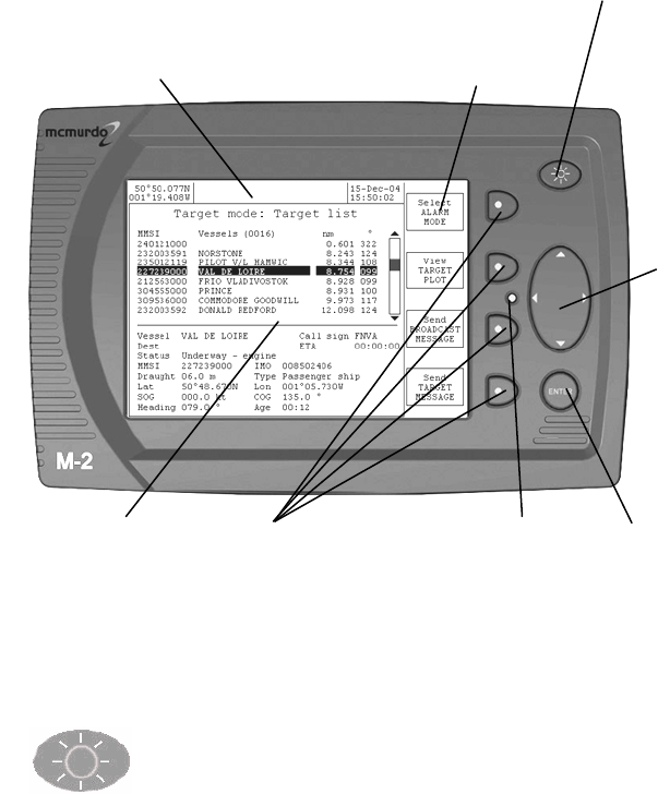
Display and controls
Setting the display backlight and contrast level
One short push of the backlight key toggles the backlight ON and
OFF.
To adjust the brightness or contrast of the display, hold down the backlight key
until the screen changes to the LCD setup page. Adjust the LCD backlight and
contrast settings using the four way navigation pad. Return to the previous page
by holding down the backlight key until the screen changes .
Data entry
confirmation key.
Second function:
Hold down this key to
access set-up mode
menus
4
-
axis
navigation
pad
(Navpad)
4 Softkey buttons
Backlight on/off key
Second function:
Hold down to enter
LCD setup mode
menus
Softkey
Label area
Display window
Alert LED
Status bar
M-2 AIS Operation Issue 1 9
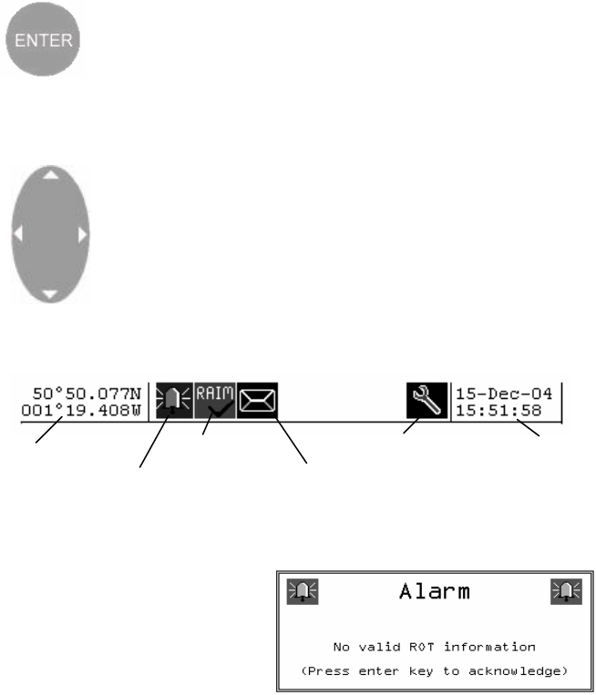
Enter key and Setup mode
The ENTER key confirms the entry of new data, and provides
additional functions:
Text entry mode, to activate the popup keyboard
Setup Mode; enter System Setup Mode by holding down the
ENTER key for more than five seconds.
Navpad
The four-way ‘Navigation Pad’ moves the cursor around the
screen.
It is also used to change data:
UP/DOWN selects the field
LEFT/RIGHT changes the value
Status bar
The information bar at the top of the display shows the current system status.
Alarm window
Alarms relate to own vessel
conditions. A new alarm state is
announced by a popup text box.
Use the ENTER key to
acknowledge the alarm state and
clear the alarm window box from
view. Alarm boxes persist until acknowledged, thus several boxes may be
stacked on top of each other.
Alert LED
The red Alert LED can be set to indicate various functions.
It will start to flash while the system is in the process of initialising after power up
and before setting to work.
Refer to the setup options section for further information.
New message
to read
Current alarm
Service mode
RAIM active
GNSS position
information as
broadcast over
AIS channels
System Date
and Time (UTC)
provided by
GNSS
10 Issue 1 M-2 AIS Operation
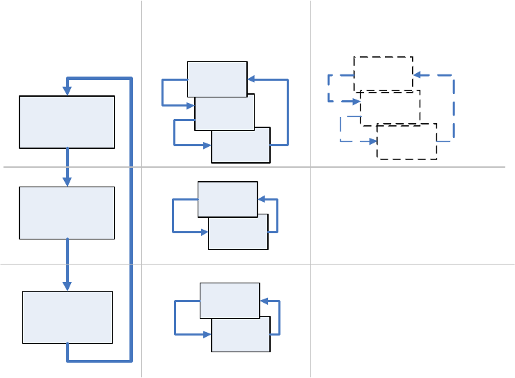
Using Softkey menus
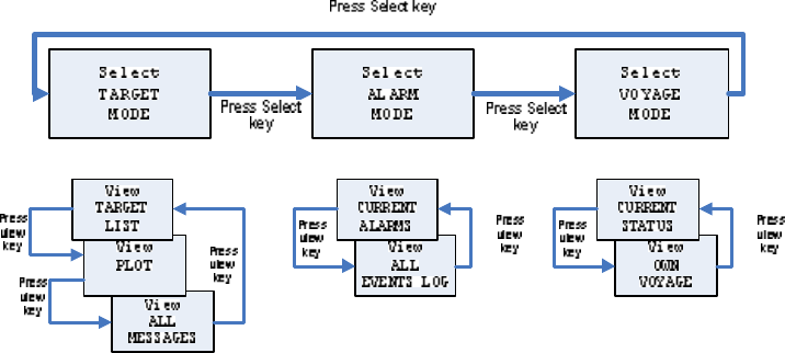
The Select softkey switches the display between the three main Modes of
operation: Voyage → Target → Alarm
The View softkey switches the display between different pages within each
main mode. A View can have several Pages associated with it; these may be
scrolled using the Page s oftkey. Some pages have further options which can be
selected by other softkeys.
Operate the softkeys in this order to get to the selection that you want:
Select → Most significant
View → significant
Page → least significant
Enter or Clear → Action confirmation
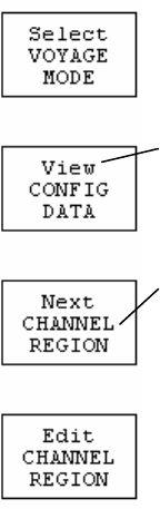
Softkey labels display the next function of each softkey that is available in the
current Mode, View or Page.
This example shows the M-2 in SETUP mode.
VOYAGE mode will appear if the key is pressed.
The top line of each softkey label indicates the function of the
associated softkey.
In this example, operating the softkey will change to the next
View, which is CONFIG DATA
The lower text of a softkey label indicates the information or
use that is associated with the next softkey action; in this
example, CHANNEL REGION
Softkey menu options cycle repeatedly through all available
selections.
M-2 AIS Operation Issue 1 11
6HOHFW
7$5*(7
02'(
6HOHFW
$/$50
02'(
6HOHFW
92<$*(
02'(
3UHVV6HOHFWNH\
3UHVV6HOHFW
NH\
3UHVV6HOHFW
NH\
9LHZ
$//
0(66$*(6
9LHZ
3/27
9LHZ
7$5*(7
/,67
3UHVV
YLHZ
NH\
3UHVV
YLHZ
NH\
3UHVV
YLHZ
NH\
9LHZ
$//
(9(176/2*
9LHZ
&855(17
$/$506 3UHVV
YLHZ
NH\
3UHVV
YLHZ
NH\
9LHZ
2:1
92<$*(
9LHZ
&855(17
67$786 3UHVV
YLHZ
NH\
3UHVV
YLHZ
NH\
6KRZ
6KRZ
6KRZ
Softkey cyclic actions
Select
key
View
key
Show
key
(contents depend on context)
12 Issue 1 M-2 AIS Operation
General operation
Entering text
A pop-up QWERTY keyboard appears when updating or inputting new
information into the M-2.
Updating text
Push the EDIT softkey. The data edit cursor will appear
highlighted on the topmost field of the page.
Push the ENTER key to activate the popup keypad.
Move the cursor over the field to enter or edit using the
navigation pad.
Move the edit cursor around the keyboard using the navigation pad to highlight
the required character.
Select SHIFT to access lower case characters and symbols .
Select DEL to delete a single character.
The <- and -> keys move the cursor over existing characters, allowing errors in
the middle of text to be corrected without deleting the entire text from the end.
M-2 AIS Operation Issue 1 13
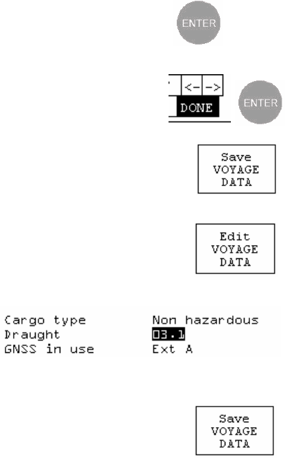
Push the ENTER key to confirm the character.
Repeat these actions until the data field is correct.
Close the edit keyboard by selecting DONE and
pushing the ENTER key.
Finally, review all the information s hown on screen. When
correct, save the new information and exit to the main menu
level using the SAVE softkey.
Entering numbers
Select edit mode using the EDIT softkey, The data edit
cursor will appear highlighted on the topmos t data field.
Position the edit cursor over the numeric field to be changed.
The current value will be highlighted.
This example shows the
vessel draught field in
edit mode.
Change the value by pressing LEFT or RIGHT on the navigation pad to increase
or decrease the value displayed.
Once the new value is set, use the UP or DOWN navigation
pad keys to move to the next item, or exit and save the
changes with the SAVE softkey.
To cancel an entry, close the keyboard by selecting DONE and then push the
View key. When the display is cycled back to the original page, the entry will be
unchanged. (In other words, the new entry is only saved by pressing the Save
key. It will still display as long as that view is displayed, but will revert to the
previous data when the view is re-selected.)
14 Issue 1 M-2 AIS Operation
Password access control
The M-2 AIS unit has three levels of access control - each of which is protected
by its own password. The three levels are:
User level protects voyage-related data such as that displayed on the
Voyage mode: Own voyage page.
Operator level protects operational data such as the channel regions shown
on the Setup mode: Channel regions page.
Service level this level of access is available only to authorised service
agents and protects ship's static data (such as the MMSI and
IMO numbers) which must be programmed into the unit.
The user and operator passwords are optional. If either of them is not required
(permitting any user to change the voyage or operating data) then they may be
set to the special password "NONE" (which is the default setting). It is
recommended that the operator password is set, and that the user password is
not used.
If a user password is configured, but the operator password is left as "NONE"
then the user password will not be effective since the system will grant operator-
level access without requiring a password.
Each page protected by a password has an Edit softkey - for instance the Own
Voyage page displays the Edit VOYAGE DATA softkey whilst the Channel
Regions page displays the Edit CHANNEL REGIONS softkey. When the Edit
softkey is activated, the user is prompted to enter the corresponding password.
Press the 'Enter' button to bring up the on-screen keyboard, and then enter
the appropriate password into the top field. Then activate the Verify
PASSWORD softkey in order to check the password. If the password is correct,
you will be granted access to the preceding page.
When the password is set to "NONE" then the user is permitted to edit the
corresponding page immediately without being prompted to enter the password.
M-2 AIS Operation Issue 1 15
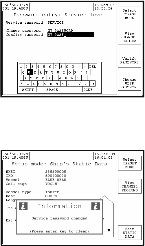
Changing passwords
Any password can be changed by using the Edit STATIC DATA softkey on the
Setup mode: Ship's static data page. Since the static data is protected by the
Service password, this softkey always causes the password prompt to be
displayed.
To change any password, select the desired password entry page (the Change
XXXXX PASSWORD softkey cycles through these pages) and enter the current
password, then enter the new password in each of the two fields, Change
password and Confirm password. Finally, press the Verify PASSWORD
softkey. Provided that the two new password entries are identical, an
acknowledgement is displayed on screen and the new password takes
immediate effect.
16 Issue 1 M-2 AIS Operation
If the new passwords are not identical, a warning message is displayed. The
original password remains valid.
Resetting lost passwords
If the user password is forgotten, the operator or service passwords may be
entered into the User password field instead, in order to allow the user
password to be re-set. Similarly, the operator password can be reset by entering
the service password as the Operator password.
The service password cannot be overridden. If this password is changed and
then forgotten, then only a Service Agent can reset the AIS to restore the default
passwords.
M-2 AIS Operation Issue 1 17
Detailed operation
Menu cyclic structure
Other softkeys display options depending on the page selected.
18 Issue 1 M-2 AIS Operation
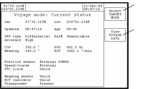
VOYAGE Mode: Current Status
VOYAGE Mode: Current status page provides an overview of the vessel’s
current navigational status . The information is updated automatically by the
onboard navigation sensors.
The Latitude and Longitude shown are the values which are transmitted to other
vessels. Updated is the time when the last transmission occurred; Age is the
length of time since the update occurred.
The MANUAL POSITION ENTRY key is not shown while the internal or
external GNSS is providing a valid navigation fix, but appears to allow this
information to be entered when necessary.
Change to
AIS target
view
Review own
voyage
status
information
M-2 AIS Operation Issue 1 19
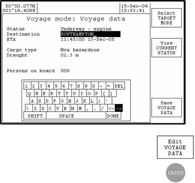
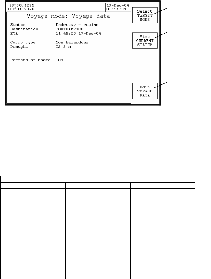
VOYAGE Mode: Own Voyage
Manually enter own voyage information, as previously described
In an installation that contains another device (such as an integrated charting
system) which is also capable of entering Voyage and Static data, consideration
must be given to the interaction between the other device and the M-2
transponder. Information entered via the M-2 display unit may be overridden by
data entered by the integrated system ; if this is the case, the integrated system
should be used as the main input device.
Voyage mode: Own Voyage
Item Description Notes
Status Not specified
Underway – engine
At anchor
Not under command
Restricted movement
Constrained by draught
Moored
Aground
Fishing
Underway – sail
Select the current
navigation status from
list.
Destination Preferably
§UN/LOCODE format
ETA HH:MM:SS
DD-MM-YY Enter UTC arrival time,
Month will auto select
Change to
AIS target
view
Change to
Voyage
mode,
Current
Status view
Update own
voyage
information,
save the

20 Issue 1 M-2 AIS Operation
by first letter, J=Jan,
F=Feb etc.
Cargo Type Fixed by vessel type
Non hazardous
IMO hazard cat A
IMO hazard cat B
IMO hazard cat C
IMO hazard cat D
Unknown
‘Fixed by vessel type’ is
the auto selected value
according to own
vessel type. Where
vessel type allows
other cargo types can
be picked from list.
Draught – 99.9
(Set value) Own vessel’s water
draught in meters.
GNSS in use Ext A
Ext B Select the source of
external GNSS data
Persons on Board 000 - 255 Set number value us ing
the Navpad keys only
§UN/LOCODE codings for locations worldwide may be found on the webpage:
www.unece.org/cefact/locode/service/main.html
M-2 AIS Operation Issue 1 21
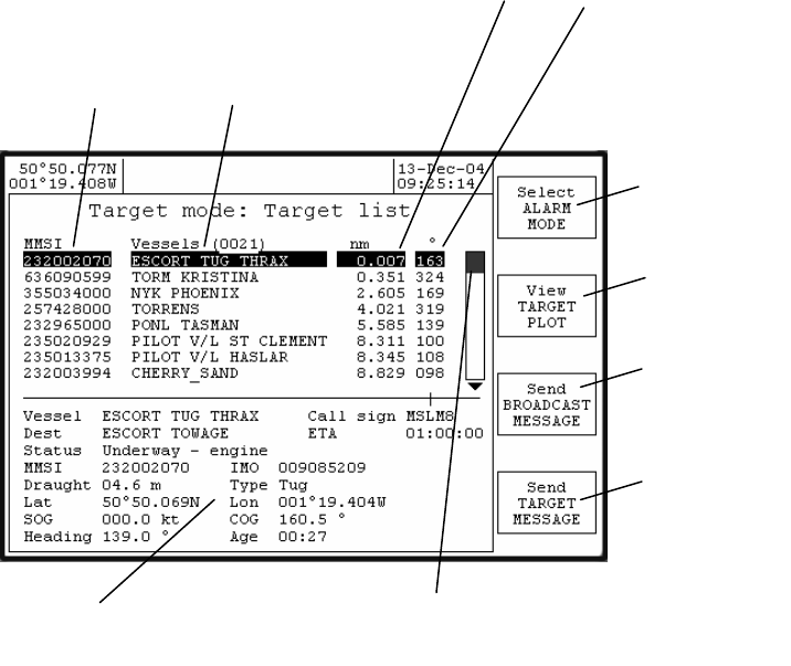
Target Mode: Target list
Targets are sorted according to range from own ship.
The destination (Dest) is preferably shown in its §UN/LOCODE format.
Age is the time since the information was updated.
§UN/LOCODE codings for locations worldwide may be found on the webpage:
www.unece.org/cefact/locode/service/main.html
NM Range and Bearing of target from
own ship.
MMSI number and Name
of ve
ssel
Expanded information for selected target
Scroll bar
indicates the highlighte
d
target’s position within the target list
Change to
ALARM mode
Change to
TARGET
PLOT view
Change to
broadcast
safety edit
page
Change to
safety edit
page
22 Issue 1 M-2 AIS Operation
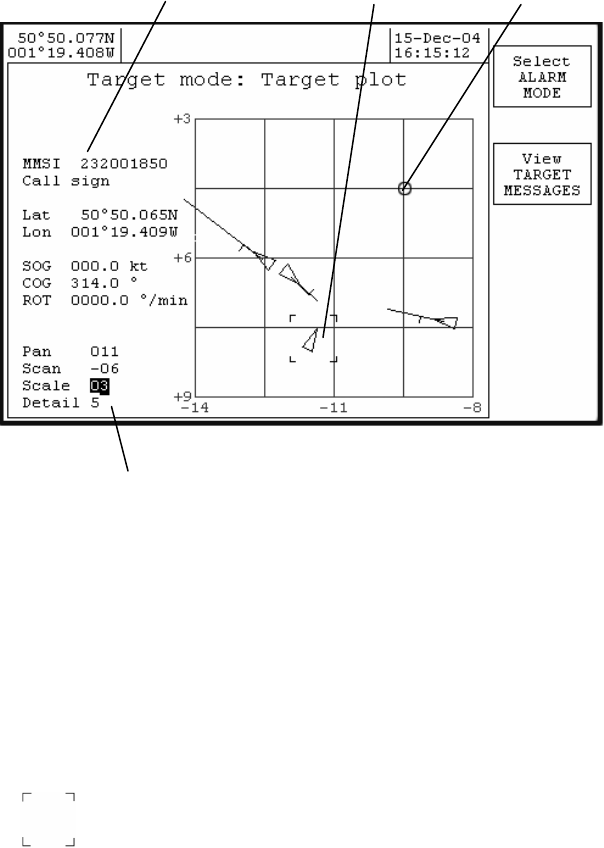
Target Mode: Target Plot
Use Navpad to step around data fields and change values
The display control section operates by selecting the desired field using the
Navpad up and down keys , then using the Navpad left and right keys to change
the parameter.
Pan shifts displayed user position East or West
Scan shifts displayed user point North or South
Scale changes the area of view (0.75 nm – 50 nm)
Detail sets the level of graphics detail associated with targets (1-5)
Repeatedly pressing the up or down Navpad key moves the cursor through the
display fields, then changes to the target cursor display, then changes back to
the display fields.
Selecting target
Use the up or down Navpad keys to change the cursor to the target display.
Target box icon will appear.
Use the Navpad to select the target of interest. The left key steps through the
targets in increasing range order, right key in decreasing range order.
Details of selected target Selected target User position

M-2 AIS Operation Issue 1 23
Target icons detail
Level 1
Target is shown as a simple cross
Level 2
Vessel outline triangle is oriented by heading
Level 3
Vessel outline triangle is oriented by heading
COG / SOG vector (fixed length)
Level 4
Vessel outline triangle is oriented by heading
COG / SOG vector (fixed length)
Turn indicated by ROT flag of fixed length
Level 5
Vessel outline triangle is oriented by heading
COG / SOG vector (fixed length)
Turn indicated by ROT flag of fixed length
Radio Call sign
2DGJ
X

24 Issue 1 M-2 AIS Operation
Reading and sending safety messages
A new incoming safety text message is first announced by the new message
popup notification window
Use the Enter key to clear the new message notification window from view.
The ‘envelope’ icon is displayed in the status bar area, indicating that a
new message is ready to read.
Working with safety text messages
Received and transmitted safety text messages are stored ready for reading,
editing or re-transmission within the All messages list.
The message list may be further sorted into message types using the Show Rx
MESSAGES or Show Tx MESSAGES softkeys.
The message list displays the beginning part of a message text. To read the
complete message, place the highlight bar over the required message; the full
text of the message will be shown in the lower section of the display.
M-2 AIS Operation Issue 1 25
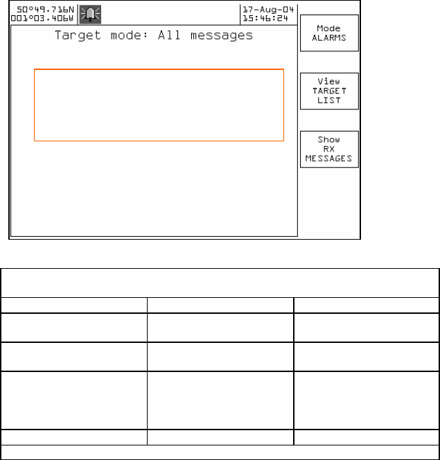
Target Mode: All messages
View all safety text messages
Softkey actions, Target mode: All messages
View all safety text messages
Softkey Function Description
Mode ALARM MODE Change to ALARM
mode.
View TARGET LIST Change to TARGET
LIST view.
Page Show Rx MESSAGES Re-sort the message
list to show only
incoming received
messages.
Action
I WILL TURN TO PORT ON YOUR
SO………
PILOT LADDER IS ON THE PORT
SID………
I WILL I
NCRESS SPEED
26 Issue 1 M-2 AIS Operation
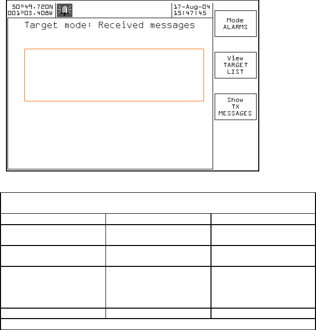
View Rx text messages
Softkey actions, Target mode: Received messages
View all received safety text messages
Softkey Function Description
Mode ALARM MODE Change to ALARM
mode.
View TARGET LIST Change to TARGET
LIST view.
Page Show TX MESSAGES Re-sort the message
list to show only
outgoing transmission
messages.
Action
PILOT LADDER IS ON THE PORT
SID………
GALE WARNING, GALE FOURCE
EIGHT IS EXPE……….
M-2 AIS Operation Issue 1 27
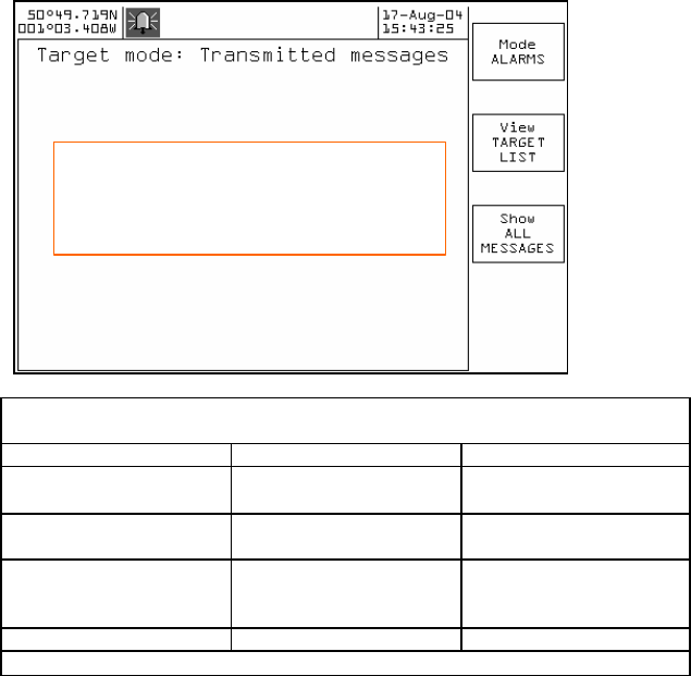
View Tx text messages
Softkey actions, Target mode: Transmitted messages
View only sent safety text messages
Softkey Function Description
Mode ALARM MODE Change to ALARM
mode.
View TARGET LIST Change to TARGET
LIST view.
Page Show ALL
MESSAGES Re-sort the message
list to show all
messages.
Action
I WILL TURN TO PORT ON YOUR
SO………
I WILL INCRESS SPEED
28 Issue 1 M-2 AIS Operation
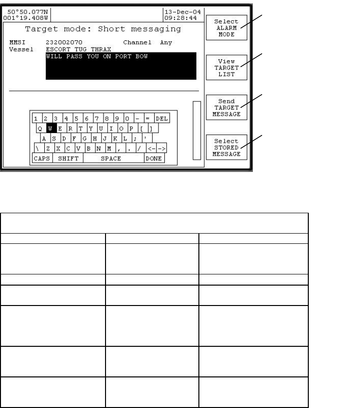
Target Mode: Short messaging, Target message
Send a target MMSI (or vessel) a safety text message.
Push the ENTER key to access the popup keyboard and start a new safety text
preparation or ‘select STORED MESSAGE’ to access previously saved
messages for reuse.
Target mode: short messaging
Send target MMSI a safety text message
Subject Value Notes
MMSI Defaults to
highlighted targets
MMSI number
Enter key to change or
‘Navpad down’ to move
to next item.
Vessel Target’s name Can’t change
Message Message text
Max 156 characters ..
Channel Any
AIS A
AIS B
Both
Set safety transmission
channel selection.
Type Addressed Can’t change, fixed by
selection of Target
MMSI.
Add new message Message text
Prepare and save safety
message text for later
usage.
Change to
ALARM mode
Change to
TARGET LIST
view.
Transmit the set
safety message
to target MMSI.
Pick a prepared
safety message
from list. Can be
sent ‘as is ’, or
edited and
resaved as a
new message.
M-2 AIS Operation Issue 1 29
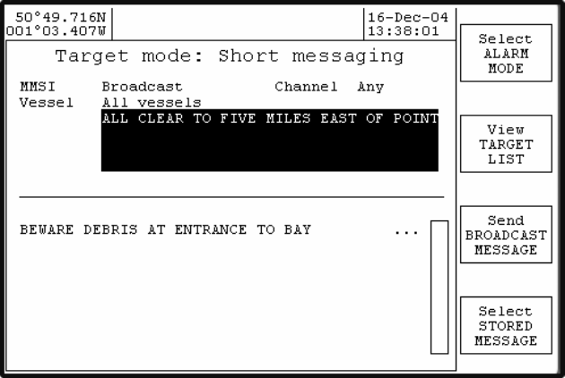
Target mode: Short messaging, BROADCAST message
Send an all ships BROADCAST safety text
Push the ENTER key to access the popup keyboard and start a new safety text
preparation or select ‘STORED MESSAGE’ to access previously saved
messages for reuse.
30 Issue 1 M-2 AIS Operation
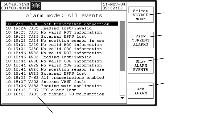
Alarm mode: All events log
This page lists all the alarm, information and security events, with the most
recent events at the top.
Acknowledging alarms
Normally, alarms are acknowledged by using the ENTER button to clear the
popup message box, which acknowledges the alarm. Unacknowledged alarms
may also be acknowledged by moving the cursor down the list to select the
unacknowledged alarm - and then using the Ack Alarm softkey.
Event codes
Codes are divided into two categories – alarm codes and log entries. Alarm
codes relate to generated alarms; event codes, distinguished by a dash (-),
relate to log entries only.
Alarm codes
Each alarm is preceded by a 4-character ID code.
The first character indicates the state of the alarm and may be 'A' for activated,
'V' for inactivated or 'C' for current.
A current alarm is an alarm which is ongoing at the present time. (Current
alarms are also shown on the current alarms page.)
An activated alarm is an alarm that occurred at the time indicated in the first
column of the alarm log, and has subsequently cleared. The ‘A’ indicates that
the record refers to the time when the alarm occurred.
Select voyage
mode
View current
alarms page
View alarm
and information
events only
Acknowledge
the selected
alarm
Event code
M-2 AIS Operation Issue 1 31
An inactivated alarm is an alarm which has cleared at the time indicated. This is
the second entry for a particular alarm – the times when it occurred and when it
cleared are recorded separately. The ‘V’ indicates that the record refers to the
time when the alarm cleared.
The second character indicates whether the alarm has been acknowledged or
not - 'A' indicates that it has been acknowledged and 'V' that it has not.
The two numeric digits are a unique code for each alarm type.
Log entry codes
Log entry codes are of two types – Security and Text. Neither event requires
acknowledgment.
Security codes are explained in the Security Log section.
Text codes denote entries in the log which may be used for fault determination
and servicing. Each text entry is preceded by a 4-character ID code. The first
character is always an 'T' for text entries, and the second character is always '-'
to indicate that acknowledgement is not required. The two numeric digits are a
unique identifier in accordance with AIS specifications.
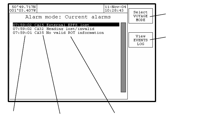
Alarm mode: Current alarms
Select
voyage mode
View all
events log
Time of alarm
Alarm code
Alarm description
32 Issue 1 M-2 AIS Operation
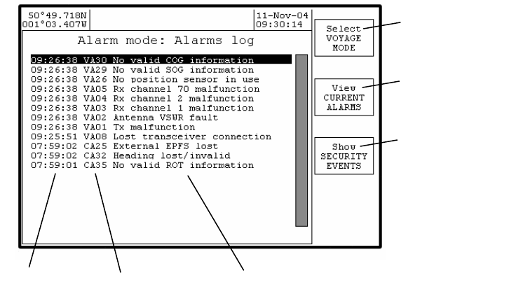
Alarm mode: Alarms log
This page lists the alarm and information events, with the most recent events at
the top. Note that these events are lost when the display unit is switched off and
therefore only reflect events that have occurred since the display was last
switched on. Events are retained for a maximum of 24 hours .
Time of alarm
Alarm code
Alarm des cription
Select
voyage mode
View current
alarms page
View security
events only
M-2 AIS Operation Issue 1 33
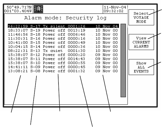
Alarm mode: Security log
This page lists the events stored in the security log. The security log stores any
event which results in the AIS transmitter being disabled for more than 15
minutes. The events in this log are retained permanently and are only deleted
when the log has reached its maximum size of 30 events.
Security event codes
Each security event is preceded by a 4-character ID code. The first character is
always an 'S' for security events, and the second character is always '-' to
indicate that acknowledgement is not required. The two numeric digits are an
index value indicating the relative position in the log of each entry.
Security event types
Tx silent - this indicates that the transponder has been placed into a silent mode
as a result of being in a location where regional channel management has
specified that the transponder should not transmit.
Tx quiet - this indicates that the transmitter has been disabled as a result of an
operator command. This is a special function that is not available on all units.
Power off - this indicates that the M-2 transponder was switched off.
Tx alarm - there has been a persistent fault with the transmitter.
VSWR alm - there has been a persistent fault with the antenna. This has not
stopped the transponder from transmitting, but performance may have
been impaired
Select
voyage mode
View current
alarms page
View combined list
of all alarm and
security events
Time of event
Security event code
Security event type
Event duration
Event date
34 Issue 1 M-2 AIS Operation
Rx1 alarm - there has been a persistent fault with the AIS channel A receiver.
Rx2 alarm - there has been a persistent fault with the AIS channel B receiver.
DSC alarm - there has been a persistent fault with the DSC receiver.
Security event durations
Each security event covers a period of time indicated by the "duration" shown on
screen. The time at which the event started (eg when the transponder was
switched off) is given by the time and date displayed. The duration for which the
event persisted (eg for how long the transponder was switched off) is given by
the duration in hours and minutes. The time at which the event finished (eg
when the transponder was switched back on) can be determined by adding the
duration to the start time/date.
M-2 AIS Operation Issue 1 35
System configuration
Select Setup Mode by holding down the ENTER key for more than three
seconds.
Use the VIEW softkey to step through the following information pages in this
order:
User Preference – set Display and transponder user options
Ship’s Static Data – set own vessel’s static information
Channel regions – set AIS region boundaries and options
Alarm selection – enable / inhibit alarms
Configuration – view system information and data port options
Serial Monitor – view diagnostic data
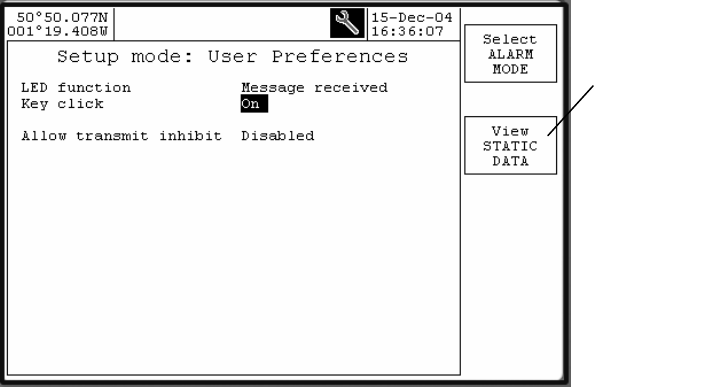
User Preference
Change
to
STATIC
DATA
view

36 Issue 1 M-2 AIS Operation
Setup Mode: User Preferences
Option Setting Notes
LED function Off
Message received
Alarm active
Usage of Display
Annunciator LED
Key click On
Off Enable / disable Display
key press sound signal
Audible alarm On
Off Enable / disable Display
audible alarm
Auto-dim backlight 00 – 15 Display LED Backlight
timeout period in minutes
00 = disable
Own reports Enable
Disable Automatic transmission
of own vessel AIS reports
Disable = silent mode
Factory default settings are shown in bold
M-2 AIS Operation Issue 1 37
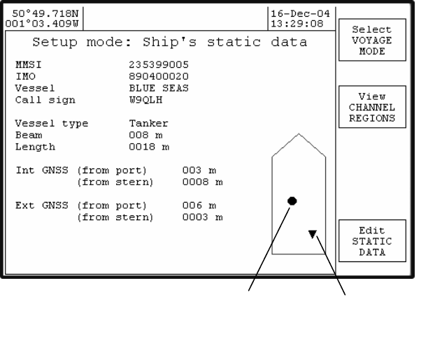
Ship’s Static Data
AIS unit
GPS antenna
External GNSS
antenna

38 Issue 1 M-2 AIS Operation
Setup Mode: Ship’s Static Data
Option Setting Notes
MMSI 9 digit number From radio licence
IMO 9 digit number From radio licence
Vessel 20 characters From radio licence
Call sign 7 character alpha
numeric From radio licence
Vessel type Select from list Unknown
WIG craft
Fishing vessel
Towing (small tow)
Towing (large tow)
Dredging
Diving operations
Military operations
Sailing
Pleasure craft
High speed
Pilot vessel
Search and rescue
Tug
Port tender
Anti-pollution
Law enforcement
Medical transport
Res 18 vessel
Passenger ship
Cargo ship
Tanker
Other type
Beam 3 digit number Set in meters
Length 4 digit number Set in meters
AIS unit
From port
From Stern
3 digit number
4 digit number
AIS GNSS antenna
reference position in
meters from Port side
and Stern
Ext GNSS
From port
From Stern
3 digit number
4 digit number
GNSS antenna reference
position in meters from
Port side and Stern
M-2 AIS Operation Issue 1 39
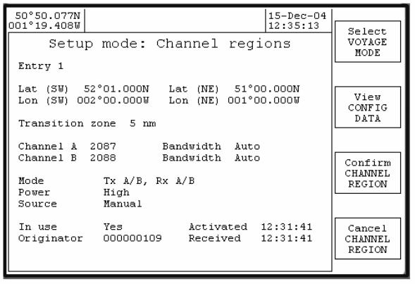
Channel Regions
Used to set geographic areas which have specific AIS channels requirements.
When entering a new channel region, the new values may be entered on any
one of the channel region pages (including region 0 - the "High Seas" region).
Once the new information has been saved and confirmed (by using both the
"Save CHANNEL REGION" and "Confirm CHANNEL REGION" softkeys) then
the new region will be allocated to a particular page according to the following
rules:
If the geographic co-ordinates match or overlap with an existing region
then the old region will be replaced by the new one.
Otherwise, the new region is stored in page 1 and the other pages
are moved downwards. If all the pages are used, the oldest region is
deleted.

40 Issue 1 M-2 AIS Operation
Setup Mode: Channel Regions
Option Setting Notes
Entry 0 - 8 LATtitude (SW)
LONgitude (SW)
LATtitude (NE)
LONgitude (NE)
Enter the coordinates of
South West box corner
then North East box
corner.
Transition Zone 1 - 8 Select ID number for
zone
Chan A 1 - 2261 Set channel number *
Chan B 1 - 2261 Set channel number *
Mode Tx A/B, Rx A/B
Tx A, Rx A/B
Tx B, Rx A/B
Rx A/B, only
Rx A only
Rx B only
Select appropriate
Transmitter and Receiver
response for AIS region
Power High
Low Select appropriate
Transmitter output for
AIS region
Source VDL addressed Region information
automatically received
over the AIS data
channel
In Use Yes
No Activate region
*Refer to ITU R M 1084-4.
Not all channel numbers are valid. UP/DOWN scrolls through valid numbers
only.
Zone “0” always indicates the “High Seas” region which has no defined
geographical coordinates. Zone “0” cannot be edited.
SW
NE
M-2 AIS Operation Issue 1 41
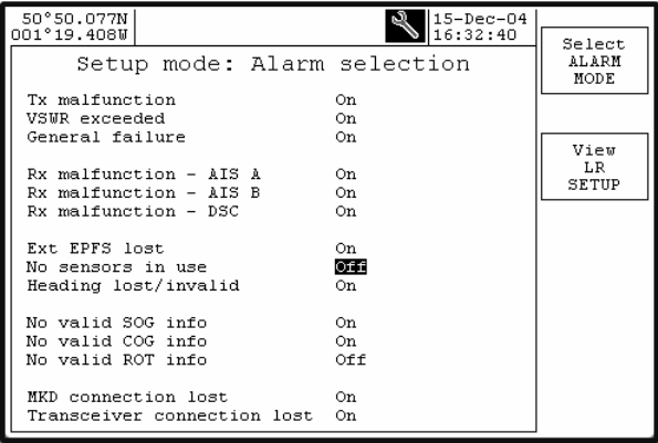
Alarm filter selection
The operation of individual system alarms may be enabled or disabled to match
system installation requirements.
If, for example, an external GNSS is not installed, then to prevent activation of
the Ext EPFS alarm set its selection to OFF in the Alarm selection page.
42 Issue 1 M-2 AIS Operation
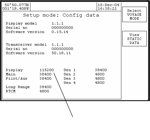
Configuration
View system version information and set data port options.
Caution: incorrect configuration of data port baud rate will stop correct
operation. A full explanation of M-2 interface protocol is printed in the separate
M-2 installation manual.
Communication baud rates
Display 115200/38400, all others
38400/4800 baud only
M-2 AIS Operation Issue 1 43
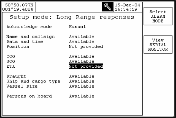
Setup mode: long range responses
44 Issue 1 M-2 AIS Operation
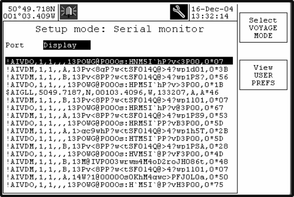
Serial Monitor
Used to view communications port data in real time, provides diagnostic
information for service technician.
Scroll Navpad left / right to select the required port data.
A full description of M-2 interface protocol is printed in the separate M-2
ins tallation manual.
NOTE: This feature requires the display unit to be connected to both the
transponder Display and Aux/Pilot connectors , and consequently cannot be
used when the Aux/Pilot connector is required for the Pilot Plug. .
M-2 AIS Operation Issue 1 45
Maintenance and Servicing
Preventative Maintenance
The UAIS transponder system is an essential part of the ship’s navigation
system and is a vital component for the safety of the ship and its crew. It is
therefore very important to maintain the system and its installation to a very high
standard. The design of the AIS transponder ensures that maintenance can be
kept to a minimum.
Display and transponder unit
To optimise performance ensure they are kept clean and grease-free. Use a
clean damp cloth, or for heavier deposits use a clean, damp cloth and a mild
solution of dish washing detergent and water. Do not use any spirit or alcohol
based solvents, gasoline or oils.
Electrical Connections
Periodically check the electrical connections; ensure that no cables are frayed or
worn, and that all connections are tight and sound.
Repair and Service
With the exception of the fuse located under the transponder cover, there are no
user serviceable parts.
Removal of the metal inspection covers other than by an Authorised Service
Technician will void warranty. If having followed the Troubleshooting Guide the
AIS is still inoperable, please call your local Service Centre.
Spare Parts
Use only manufacturer’s genuine spare parts. No liability can be accepted for
equipment failure due to incorrect replacement parts being used.
Worldwide Sales and Service
For a complete list of worldwide sales and service agents, please contact your
product supplier.

46 Issue 1 M-2 AIS Operation
Troubleshooting
Transponder status indicators
Remove the transponder dust cover to view status of indicator lamps (LED).
Rx LED ON continuously System fault
Rx LED OFF continuously Check antenna connection
Check for targets in range
System fault
Tx LED ON continuously System fault
Tx LED OFF continuously Check for “No own reports” setting
(silent mode)
System fault
OK LED ON continuously System healthy
OK LED OFF continuously Check error code on Display
PWR LED ON continuously System healthy
PWR LED OFF continuously Check fuse
Check ship’s supply
System fault
For all system faults, contact the nearest Service Centre.
Rx
red LED flashes when a signal is received
Tx red LED flashes when transmitter is active
OK LED on when BITE remote alarm relay is deactivated (no alarm
active)
PWR LED on whenever power is applied and the system fuse is
good.

M-2 AIS Operation Issue 1 47
Reviewing Alarm Mode information
Alarm Mode: All events log
View a list of all system alarm events and UTC time of alarm event activation.
Alarm Mode: View current alarms page
View a list of alarm events that are still active and the UTC time of activation.
Before calling an authorised Service Centre perform the following checks and
note detail of any alarm events:
Symptom Cause Cure
Display will not power
up No power to the
transponder unit
Cable or plug fault
System fault
See below
Also check cabling and
plug connections.
Transponder PWR
(power) LED (under
dust cover) is OFF
No power to
transponder
Transponder fuse is
blown.
Verify that power supply is
available at the
transponder power input
connector
Check / replace
transponder fuse.
No text on Display
screen or too dark or
lacking in contrast
Poor LCD backlight
and/or contrast
adjustment
Adjust LCD backlight
and/or contrast. Hold
Display dimmer key for 5
seconds to enter display
setup mode.
Antenna VSWR fault
alarm activates VHF Antenna
installation Check the VHF coaxial
cable/connections
Check VHF antenna for
damaged.
Tx malfunction alarm
activates System fault Contact Service Centre
Tx or Rx channel 1, 2,
DSC malfunction alarm System fault Contact Service Centre
Position sensor not
available alarm Internal and external
GNSS / GPS signal lost Check AIS GNSS /GPS
antenna coaxial
cable/connections
Check GPS antenna for
damage
Check that external GNSS
is working correctly
External EPFS lost
alarm GNSS / GPS signal lost Check that external GNSS
is working correctly
No Valid COG and
SOG alarm GNSS / GPS signal lost Check that external GNSS
is working correctly
No Valid SOG alarm Bottom track log Check function of Bottom

48 Issue 1 M-2 AIS Operation
Symptom Cause Cure
track log
No Valid ROT alarm Gyro compass Check gyro compass
Heading lost/invalid
alarm Gyro compass Check gyro compass or
gyro interface unit
Lost transceiver
connection Display / transponder
connection fault
System fault
Check Display
connections
Contact Service Centre
M-2 AIS Operation Issue 1 49
Alarm Messages
The transponder may generate various alarm and information messages that
appear as pop-ups on the display. Messages categorised as "alarms" also
cause the transponder to generate an audible or visual alarm (depending on the
installation) and must be acknowledged on the display unit in order to clear the
alarm. Messages categorised as "information" do not require any specific action
and the pop-up window on the display unit will automatically disappear after 30
seconds. All these messages are stored in the "alarms list" that can be viewed
on the "Alarm mode: Alarms log" page on the M-2 display unit.
The messages which may appear are listed in numeric order.
Tx malfunction (Alarm 01)
This indicates that there is a problem with the transponder. The occasional
occurrence of this alarm may be caused by transient conditions and does not
necessarily indicate a permanent problem. However, if this alarm occurs on a
regular basis you should take action to have your installation checked by an
authorised service agent.
Antenna VSWR exceeds limits (Alarm 02)
This indicates that there is a problem with the antenna. The transponder is likely
to be still operational, although its performance may be impaired. The
occasional occurrence of this alarm may be caused by transient conditions and
does not necessarily indicate a permanent problem. However, if this alarm
continues to occur you should take action to have your installation checked by
an authorised service agent.
Rx Channel 1 malfunction (Alarm 03)
Rx Channel 2 malfunction (Alarm 04)
Rx Channel 70 malfunction (Alarm 05)
These messages indicate that there is a possible problem with the receiver for
AIS channel A, AIS channel B or the DSC channel 70 respectively. Again, the
occasional occurrence of this message should not be cause for alarm, but the
regular occurrence of these messages is likely to indicate a permanent problem
which should be investigated by an authorised service agent.
Transceiver connection lost (Alarm 08)
This message indicates that the M-2 display unit can no longer communicate
with the M-2 transponder. This may indicate a problem with the connections, or
may indicate that the transponder is no longer operating correctly. This fault
should be investigated immediately. It is important to note that there is a safety
timer in the transponder which causes it to shut down automatically if the
transmitter should remain on for too long. In this event, the transponder will shut
down and this alarm will be raised by the display unit. The situation can be
resolved by disconnecting the power from the transponder for a short time and
then re-connecting it again.
50 Issue 1 M-2 AIS Operation
External EPFS lost (Alarm 25)
This message indicates that the transponder is no longer receiving data from the
vessel's on-board GPS system. This message should be investigated
immediately.
No position sensor in use (Alarm 26)
This message indicates that the M-2 transponder is unable to obtain a location
fix from either the internal GPS module or from the ship's own GNSS system.
This message may occur during the first few minutes of operation while the
transponder waits to obtain its location, and may safely be ignored during this
time. If the message occurs at any other time, it indicates a possible problem
with the GNSS antennae or wiring and should be investigated immediately
No valid SOG information (Alarm 29)
No valid COG information (Alarm 30)
Heading lost/invalid (Alarm 32)
No valid ROT information (Alarm 35)
These messages indicate that information from various sensors - ie the Speed
over Ground, Course over Ground, heading and Rate of Turn respectively - are
not available. In a full installation it is expected that all this information will be
available permanently and the display of one or more of these messages is an
indication that there may be problems either with the other sensors or with the
connections between the sensors and the M-2 transponder unit. Such
messages should be investigated immediately.
UTC clock lost (Information 07)
This message indicates that internal GPS module within the M-2 transponder is
unable to obtain a valid time signal. If this message appears on a regular basis it
may indicate a problem with the GNSS antenna connection, but it is possible for
this message to occur temporarily in certain locations or in extreme weather
conditions where the GNSS module is unable to receive transmissions from a
sufficient number of satellites.
External DGNSS in use (Information 21)
External GNSS in use (Information 22)
Internal DGNSS in use (beacon) (Information 23)
Internal DGNSS in use (msg 17) (Information 24)
Internal GNSS in use (Information 25)
These messages indicate which source of GNSS information is currently in use
by the transponder. The external GNSS information from the ship's main on-
board systems may or may not be augmented by differential correction
information - in which case the messages show "DGNSS" rather than "GNSS".
When the external GNSS signals are not available, the M-2 transponder uses
GNSS information from its own internal GNSS module and the message
changes to "Internal GNSS". This information may be augmented by the receipt
of differential correction data from a beacon receiver or by VHF transmissions
from a base station - in which case the status message shows "DGNSS" and
M-2 AIS Operation Issue 1 51
"beacon" or "msg 17" respectively to indicate the source of the differential data
being used.
External SOG/COG in use (Information 27)
Internal SOG/COG in use (Information 28)
These messages indicate whether Speed over Ground and Course over Ground
are being supplied by the external sensors or are being calculated from the
internal GNSS module.
Heading valid (Information 31)
This message is received when a valid heading is first received from the ship's
sensors.
Rate of Turn indicator in use (Information 33)
Other ROT source in use (Information 34)
The first of these messages indicates that the M-2 transponder is using Rate of
Turn information from an on-board device which directly calculates the rate of
turn - such as a gyro compass. The second message indicates that the rate of
turn is being calculated from changes in the ship's heading.
Chan management params changed (Information 36)
This message is issued each time that any of the channel management
parameters are altered. These may be altered by the receipt of specific VHF or
DSC messages from base stations and can also be modified directly by using
the "Channel Regions" page on the M-2's display unit.
All transmissions enabled (Information 63)
All transmissions disabled (Information 64)
These two messages indicate that all transmissions by the transponder have
been enabled or disabled as appropriate. When the transponder is first powered
up it is not allowed to transmit for a period while it listens to transmissions from
nearby vessels in order to ensure that it does not interfere with them. The
message "All transmissions disabled" is displayed as a reminder that the AIS is
not operational for this time. After approximately 90 seconds, the transponder
will begin transmissions and the message “All transmissions enabled" is
displayed.
These messages are also generated if the transmitter is inhibited while the AIS
unit is in operation.
Own reports enabled (Information 65)
Own reports disabled (information 66)
These messages are displayed when the transmission of AIS "Own Vessel"
reports are enabled or disabled as a result of moving across the boundary of
channel management region. When moving into a channel management region
52 Issue 1 M-2 AIS Operation
in which AIS transmissions are disabled, the message "Own reports disabled" is
displayed as a reminder that no AIS information is being transmitted. When the
vessel moves out of that channel region (or the transmission mode with in that
region is updated) the message "Own reports enabled" is displayed as a
reminder that normal operation has been restored.
Area setting uses invalid mode (Information 67)
This message is output by the transponder when an attempt is made to
configure a channel management region which has value for the 'mode' field
which is greater than 5 (the maximum permitted by IEC 61162-1).
Area setting uses unsupported mode (Information 67)
This message is output by the transponder when an attempt is made to
configure a channel management region which has value for the 'mode' field of
either 3 or 4, as these modes are not supported by this transponder.
Area is too small (Information 67)
Area is too large (Information 67)
One of these two messages will be output by the transponder when an attempt
is made to configure a channel management region which has at least one side
which is shorter than 20 nm longer than 200 nm.
Transition zone is too large (Information 67)
This message is output by the transponder when an attempt is made to
configure a channel management region which has a transition zone size of
more then 5 nm .
Area setting has corner conflict (Information 67)
This message is output by the transponder when an attempt is made to
configure a channel management region of which one corner lies to close to the
corners of existing regions. It is not permissable to have more than two regions
sharing a common corner, or for three or more reigons to have corners within
8nm or each other.
Area overruled by prior command (Information 67)
This message is output by the transponder when an attempt is made to
configure a channel management region which overlaps with a region which has
been set by either DSC tele-comand or by a VHF message within the last two
hours. Regions received by these means cannot be changed by manual editing
until at least two hours after they have been received.
Area setting uses invalid channels (Information 67)
This message is output by the transponder when an attempt is made to
configure a channel management region in which either (or both) of the
specified AIS channels are not valid channel num bers as defined in ITU-T
M.1084 Annex 4.
M-2 AIS Operation Issue 1 53
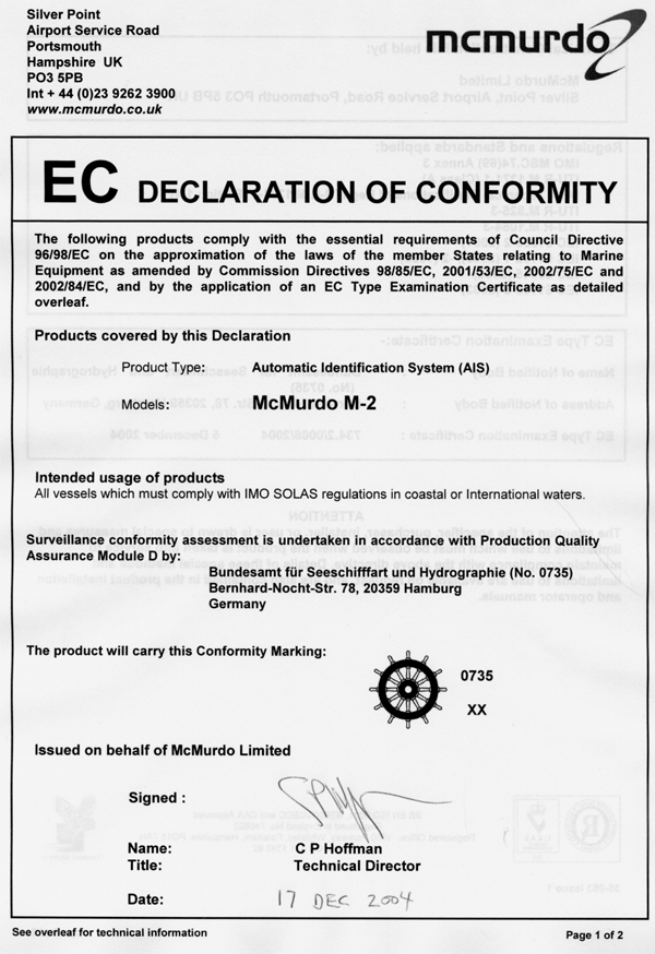
Declaration of Conformity
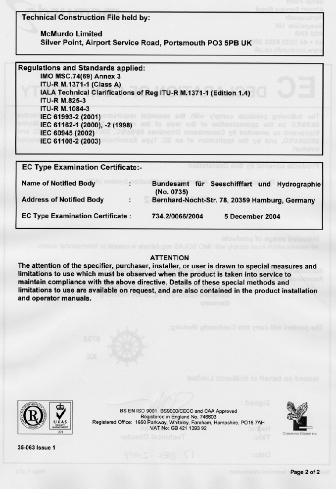
54 Issue 1 M-2 AIS Operation
M-2 AIS Operation Issue 1 55
Index
AIS .....................................................................................................................................2
Alert LED.........................................................................................................................9
ARPA................................................................................................................................3
backlight..........................................................................................................................8
Changing passwords...........................................................................See Password
DGNSS.............................................................................................................................5
Display.............................................................................................................................3
Dynamic data .................................................................................................................3
ECDIS...............................................................................................................................3
Enter key .........................................................................................................................9
Entering numbers...................................................................................................... 13
Entering text................................................................................................................ 12
GNSS................................................................................................................................3
GPS...................................................................................................................................3
keyboard........................................................................................................................ 12
Licensing..........................................................................................................................4
Navpad.............................................................................................................................9
Password....................................................................................................................... 14
Resetting lost passwords...................................................................See Password
ROT...................................................................................................................................3
Safety................................................................................................................................3
Softkey........................................................................................................................... 10
Static data.......................................................................................................................3
Status bar........................................................................................................................9
Target icons................................................................................................................. 23
Transponder...................................................................................................................3
UN/LOCODE codings............................................................................................20, 21
VDL....................................................................................................................................4
Voyage data....................................................................................................................3
VTS....................................................................................................................................4

56 Issue 1 M-2 AIS Operation
35-061 Issue 1