Orolia NAV5PLUS-1 NAV5plus User Manual User Guide
Orolia Ltd NAV5plus User Guide
UserManual.wiki
>
Orolia
>
NAV5PLUS 1 User Manual
User Guide
Navigation menu
Upload a User Manual
Namespaces
Wiki Guide
HTML
PDF
Info
Views
User Manual
Discussion / Help
Navigation
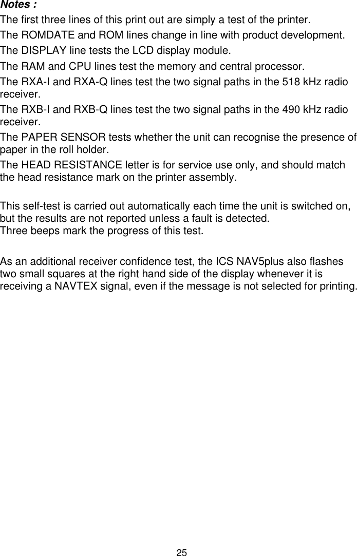
![24SELF TESTIf you have any doubts as to whether the ICS NAV5plus is working correctlyrun the self-test.‘Self Test’ is selected by holding down the feed button while the ICSNAV5plus is switched on using the power button.The ICS NAV5plus will print out the test results and then start normaloperation.If all tests are passed, a printout will appear as shown: pqrstuvwxyz{“}~ HIJKLMNOPQRSTUVWXYZ[\]^_’abcdefghijklmno !”#$%&’()*+,-./0123456789:;<=>/?@ABCDEFG ROMDATE : Nov 21 2002 ROM : ICS NAV5plus V2.07 DISPLAY : PASS RAM : PASS CPU : PASS RXA-I : PASS RXA-Q : PASS RXB-I : PASS RXB-Q : PASS PAPER SENSOR : PASS HEAD RESISTANCE : C ** Either A, B or C will show here.](https://usermanual.wiki/Orolia/NAV5PLUS-1/User-Guide-459016-Page-28.png)