Orolia S4-1 S4 SART User Manual
Orolia Ltd S4 SART
UserManual.wiki
>
Orolia
>
S4 1 User Manual
User Manual
Navigation menu
Upload a User Manual
Namespaces
Wiki Guide
HTML
PDF
Info
Views
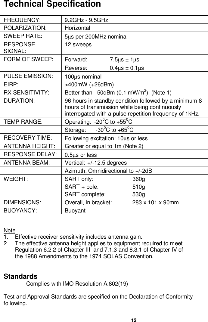
User Manual
Discussion / Help
Navigation